


INSTALLATION AND
OPERATION INSTRUCTIONS
V510 Smartphone Video Doorbell
4-Wire IP AHD Video Door Phone
10'' Display Series
User Manual

Return to Stock to Stock
Video Intercom
Product returns require a Return MerchandiseAuthorization Number(RMA). Please call
customer service at 877-435-0670 to receive your RMAnumber, BEFORE returning any
merchandise. Any product returned without an RMA number is subject of being refused and
returned to customer. Once received Intrasonic Technology will evaluate the returned items
for damaged and completeness.A credit memo will be issued to the customer once the
product has been evaluated.Any damaged or missing items will be deducted from the amount
credited. Return to stock items must be in unopened original boxes and in like new condition.
Credit will not be issued for used or previously installed product. All returns are subject to a
10% restocking charge.
Intrasonic Technology 2 Year Limited Warranty
Intrasonic Technology warrants its products to be free of manufacture defects for 2 years of
closing or actual installation. This warranty only applies to products purchased from authorized
dealers or distributors. If proof of installation cannot be supplied the manufactures serial
number or date code will be substituted. This warranty extends to the original user or subsequent
owner of the product during the warranty term. Intrasonic Technology will replace or repair
the product at its discretion at no charge with a reconditioned or new product.All products
with manufactured defects must be returned to Intrasonic Technology, Inc.
If an Intrasonic Technology product is determined to have a manufactures defect, please call
our toll free number (877-435-0670) before any attempt to dismantle the product.Any attempts
to dismantle the product will void the warranty.
An RMA (Returned Material Authorization) will be required prior to returning a product
to Intrasonic Technology, Inc. To obtain an RMA call our toll free number (877-435-0670) and
speak with a customer service representative.All products returned to Intrasonic Technology
without an RMA will be refused.
Intrasonic Technology will not be liable for consequential, incidental or damages arising in
connection with use or inability to use this product. In no event shall Intrasonic Technology
liability hereunder exceed the cost of the product covered hereby. No person is authorized
to assume for us or obligate us for any other liability in connection with thesale of this product.
Some states do not allow the exclusion or limitation of consequential, incidental or damages,
so the above limitation or exclusion may not apply. This limited warranty gives you specific legal
rights, and you may also have other rights, which may vary state to state.
Warrants its products for two years of closing or actual installation. This warranty only applies
to products purchased from authorized dealers or distributors. If proof of installation cannot be
supplied the manufacture serial number or date code will be substituted. This warranty extends
to the original user or subsequent owner of the product during the warranty term. Intrasonic
Technology will replace or repair the product at its discretion at no charge with a reconditioned
or new product. All products with manufactured defects must be returned to Intrasonic
Technology, Inc.
Wireless Speaker Kit
Warrants its products for two years of closing or actual installation. This warranty only applies
to products purchased from authorized dealers or distributors. If proof of installation cannot
be supplied the manufacture serial number or date code will be substituted. This warranty
extends to the original user or subsequent owner of the product during the warranty term.
Intrasonic Technology will replace or repair the product at its discretion at no charge with a
reconditioned or new product.All products with manufactured defects must be returned to
Intrasonic Technology, Inc.
Speakers
Intrasonic Technology 10 Year Limited Warranty for Ceiling and In-Wall Speakers
2 Year Warranty for Subwoofer and Accessories
Intrasonic Technology, Including JAAudio In-Wall and Ceiling Speakers warrants for 10 years
of closing or actual installation. This warranty only applies to products purchased from
authorized dealers or distributors. If proof of installation cannot be supplied the manufacture
serial number or date code will be substituted. This warranty extends to the original user or
subsequent owner of the product during the warranty term. Intrasonic Technology will replace
or repair the product at its discretion at no charge with a reconditioned or new product.All
products with manufactured defects must be returned to Intrasonic Technology, Inc.
1 2

Table of Contents
Table of Contents
LIMITATION OF LIABILITY..............................................................................1
DISCLAIMER OF WARRANTY.........................................................................1
SAFETY INSTRUCTIONS...............................................................................1
CARING FOR THE ENVIRONMENT BY RECYCLING........................................2
COPYRIGHT STATEMENT..............................................................................2
Table of Contents ...........................................................................................3
1. Description Of The Indoor Unit.....................................................................5
1.1 Fitting for the indoor monitor...................................................................5
1.2 Specifications of the indoor monitor ........................................................5
1.3 Note on wiring connection......................................................................6
1.4 Installation process of indoor units .........................................................7
1.5 Wiring diagram............... ......................................................................8
1.6 Description on the indoor monitor...........................................................9
1.7 Operation Introduction ........................................................................10
2. System Settings For Indoor Units................................................................13
2.1 Mouse Control.....................................................................................13
2.2 Tool Bar ..............................................................................................14
2.3 Tool Bar Menu Options .........................................................................14
2.3.1 Setup .........................................................................................14
2.3.2 Manual Recording .......................................................................14
2.3.3 Video Playback ...........................................................................14
2.3.4 Photo..........................................................................................15
2.3.5 Volume Setting ............................................................................15
2.3.6 E-Zoom mode..............................................................................15
2.3.7 Channel Status display ................................................................16
2.4 Menu Options .....................................................................................16
2.4.1 System .......................................................................................16
2.4.1.1 System-Basic ...................................................................16
2.4.1.2 System-Time ....................................................................17
2.4.1.3 System-Video...................................................................17
2.4.2 Door ...........................................................................................18
2.4.2.1 Door Setting - Basic ..........................................................19
2.4.2.2 Door Setting - Ring ...........................................................19
2.4.3 Network ......................................................................................20
2.4.3.1 Network-Basic ..................................................................20
2.4.3.2 Network-Port ....................................................................20
2.4.3.3 Network-Advanced ............................................................21
2.4.4 Record Scheduling .......................................................................23
2.4.5 Alarm ..........................................................................................24
2.4.6 Maintenance ........................ .......................................................25
2.4.6.1 SD ....................................................................................25
2.4.6.2 Upgrade ........................................................................... 26
2.4.7 User ......................................................................................... 26
2.4.8 Default ......................................................................................29
2.4.9 Information ............................................................................... 29
2.4.10 Save/Exit.................................................................................29
3. Web Browser Operation............................................................................30
3.1 Feature.............................................................................................30
3.2 Network Security Setting....................................................................30
3.3 Connection Settings ..........................................................................31
3.4 Control Download and Installation ......................................................32
.5 Operation Interface ...........................................................................33
3
3.5.1 Live..........................................................................................33
3.5.2 Controls ...................................................................................34
3.5.3 Other Operations.......................................................................34
3.5.4 Playback ..................................................................................34
3.5.5 Toolbar Guide........... ................................................................36
3.5.6 Remote Settings........................................................................36
3.5.7 Local Settings ...........................................................................39
3.5.8 Logout .....................................................................................39
4. Mobile Phone Software Visit ......................................................................39
4.1 Iphone Mobile or Ipad .........................................................................39
Appendix 1.Accessing the indoor unit via Mozilla Firefox .................................41
Appendix 2.Accessing the indoor unit via Google Chrome................................41
Appendix 3. Remote Control(Optional) ...........................................................42
Appendix 4
How to ensure reliable remote viewing of the indoor device through IE browser on Win7/Win8 64bit OS..43
3
4

1. Description Of The Indoor Monitor
1.1 Fitting for the Indoor Monitor
Hang up
Talk
Unlock
Monitoring
Up/+
Volume
Down/-
4-Wire IP Video Door Phone
10’’Display
User Manual
(Optional)
Indoor Monitor --------------------------------------------------------------------------------- 1 pcs
Screw Anchors -------------------------------------------------------------------------------- 4 pcs
Wall Screws ------------------------------------------------------------------------------------ 4 pcs
Bracket ------------------------------------------------------------------------------------------ 1 pcs
4 Pin Line ----------------------------------------------------------------------------------------5 pcs
This Quick Guide------------------------------------------------------------------------------- 1 pcs
External Switching Power Adapter(Optional)-------------------------------------------- 1 pcs
USB Mouse(Optional)------------------------------------------------------------------------- 1 pcs
Optional
1.3 Note On Wiring Connection
The indoor monitor with a separate power supply or an external power supply is optional. please
refer to actual control using. If the indoor monitor with a built-in power supply, applicable to wide
voltage range(AC 100V~240V). Please first pull out the AC power plug before installation of
device(shown as below).
Please note the silk printing marked on PCB in order to avoid incorrect connecting.
The wiring connection :requirement
1. 4C ordinary non-STP wiring cable;
2. rom the outdoor camera to furthest indoor monitor:Effective distance f
Transmission 28m (4x0.2mm )≤
Transmission 50m (4x0.3mm )
Transmission 80m (4x0.5mm )
DC12V
AUDIO
GND
VIDEO
≤
≤
Non-STP wiring cable
2
2
2
DC12V
AUDIO
GND
VIDEO
1.2 Specifications of the Indoor Monitor
309mm
Hang up
Talk
Unlock
Monitoring
Up/+
Volume
Down/-
24.7mm
197mm
Display
Resolution
Video system
Intercom mode
Conversation duration
Power consumption
Power supply
Operation temp.
Installation
Dimensions
External Switching Power Supply(DC 12V/2A)--Optional
Built-in power supply( AC100V~240V)--Optional
10.1 inch TFT LCD(16:9)
1024*600
PAL/NTSC compatible
Semi-duplex communication
120 seconds
12W max.
-10 C~+60 C
Surface mount
309*197*24.7mm
Wire connection according to the following to avoid interference:
Power+ Video
Audio
5
6
GND
Power+ Video
GND
Audio
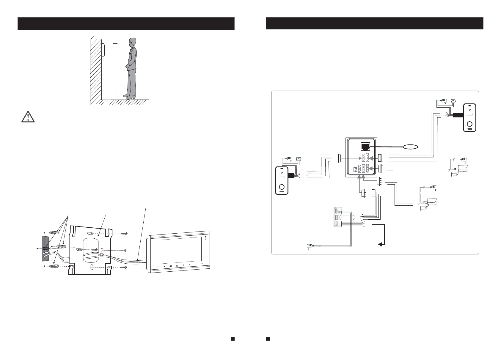
1.4 Installation Process of Indoor Units
150-160cm
1.5 Wiring Diagram
For IP 10’’ AHD display series, users can connect up to 2 AHD(720P) outdoor doorbells or 2 IP outdoor
cameras, 2 CCTV cameras and three extension CVBS indoor monitors(video door phone) one by one
to the corresponding interfaces . The power supply with a built-in power or an external power is optional.
NOTE:
* Switch off power supply before installing.
Keep
*
more than 30cm away from AC power supply to avoid external interference.
To install the indoor unit , please follow these steps as below:
Connection
cable
Screw anchors
Bracket
Volume
Up/+
Down/-
IP indoor monitor
Unlock
Talk
Monitoring
AC/DC power adapter
for lock(not included)
IP Indoor Monitor
(Main)
AC/DC power adapter
for lock(not included)
Lock(not
included)
DC12V
AUDIO
VIDEO
DC12V
AUDIO
GND
VIDEO
DOOR2
GND
Speparate power supply
DOOR2
IN
OUT
Indoor monitor
(slave)
External switching power supply (DC 12V)
Hang up
Network
DOOR2
DOOR1
Power
CAM2
OUT
CAM1
AUDIO
GND
DATA
VIDEO
OUT
AUDIO
GND
DATA
VIDEO
AUDIO
GND
DATA
VIDEO
To next extention unit
DC12V
AUDIO
GND
VIDEO
DOOR1
DC12V
AUDIO
GND
VIDEO
CAM1
DC12V
AUDIO
GND
VIDEO
CAM2
Internet
AC/DC power adapter for
camera(not included)
DC 12V
GND
Video
CAM2
DC12V
AUDIO
GND
VIDEO
AC/DC power adapter for
camera(not included)
GND
VIDEO
Lock(not
included)
DC 12V
DOOR1
CAM1
7
8

1.6 Description On The Indoor Monitoring
1
14
15
10
11
12
13
2
Up/+
Down/-
6
Volume
7
8
9
10
Talk
Monitoring
11
Name
TFT display
Microphone
3
5
6
7
Down/-
Up/+
Volume
8
9
Monitoring
Tal k
Unlock
Hang up
Speaker
USB Port
SD Port
View visitor’s image displayed on the TFT screen
Transmit the voice to outdoor camera
Power LED
Network LED
1. Decrease volume.
2. On menus press the button to move the cursor downwards.
1. Increase volume.
2.On menus press the button to move the cursor upwards.
1. Adjust volume.
2. On menus press the b utton to move the cursor leftwar ds.
1. Transfer call, press the button transfer call to another indoor monitor.
2. On main menu or sub-menu, press the button to move the cursor
rightwards.
Monitoring, press the button to watch the outdoor doorbell and CCTV
camera images.
1. Talk, press the button to activate conversation mode.
2. In standby mode, press this button to intercom call to another indoor
monitor.
1. Unlock, release the door lock.
2. On main menu or sub menus, press the button to confirm.
1. Hang up, press this button to end conversation mode.
2. In standby mode, press the button once to access the menu bar.
3. On menus press the button to exit the current menu interface.
Sound from outdoor camera.
To connect the USB mouse to t he device.
SD card interface, support up to 128G SD card for recording and captures. If
the SD card is less tha n 64GB, it must be formatted as fat3 2 before using. If the
SD card is more than 64GB, it must be formatted as exFAT before using. And
suggest that it’s better to use a SD card more than class 10 onto the device.
Hang up
Unlock
12
13
Descriptions
1.7 Operation Introduction
VISITOR CALL
3
4
5
14
15
16
◆
Please be aware of Connection of 2 outdoor cameras is required.
Standby mode
The Visitor press
the button on
call
outdoor camera 1
10s of continuous
ring tone is heard
inside and outside
The visitor’s image
automatically displayed on
the screen
Press the
button
talking
Tal k
Stop ringing
Start conversation
with outdoor camera
The indoor unit will automatically go into standby mode if you are not
at home or have not reached the indoor unit in 60s.
The conversation
duration is 120s
at a time
Press the
button on indoor
monitor
unlock
release the
door lock
Both the visitor s voice and image will be not switched off within 20s of time span when the
button is pressed.unlock
For the models with SD card, if the SD card has been inserted into the indoor monitor,
when some visitor press the call button on outdoor doorbell, the device will start
recording with audio.
If a conversation with an outdoor doorbell is underway in monitoring mode, during this
time a visitor press the call button on another outdoor doorbell, a beep from the indoor
monitor will be heard.
The Visitor press
the button on
call
outdoor camera 2
NOTICE:
Press the button
Hang up
on indoor monitor again
End
9
10

MONITORING
◆
Please be aware, Connection of 2 outdoor cameras to 1 indoor monitor is required for dual
entrance monitoring at least.
Standby mode
Press the
monitoring
button on indoor
monitor
display image from 1st
outdoor camera on the
screen.
Press the
monitoring
button on indoor
monitor again
display image from 2nd
outdoor camera on the
screen.
monitoring duration
is up to 60s a t a ti me
Press the
talking
button
Start conversation
with outdoor camera
Press the
Hang up
button again
Tal k
Hang up
Press this button once
more to return to
standby mode
Press the
unlock
button to release
the door lock
End
NOTICE:
If you are using only one outdoor camera in mode, you can also end the
monitoring monitoring
mode by pressing the button again.
monitoring
CALL TRANSFER TO OTHER EXTENSION
◆
At least 2 indoor units is required
Outdoor camera call indoor
monitor and conversation
is underway
NOTICE:
When you are transferring a call to other extension, the original
conversation indoor unit will return to standby mode.
Press this button to access
Call transfer to
other extension
A continuous Ding
Dong tone is heard
Press tonhe
button any of
talking
Talk
Start conversation
with outdoor camera
indoor units
NOTICE:
To release door lock, end conversation; please page 10 as reference.refer to
INTERNAL COMMUNICATION AMONG INDOOR UNITS
◆
At least 2 indoor units is required
Standby mode
Press the
talking
button
Talk
NOTICE:
In mode, if a visitor press the call
internal communication
button on either outdoor unit, the
mode will be switched off. The visitor s image will appear
on its screen and continuous ringing will be heard. you can
A continuous Ding
Dong tone is heard
Press tonhe
talking
button any of
press the button to reactivate
visitor; for more detailed operations, please refer to
CALL
Tal k
talking conversation with the
on page 10.
indoor units
internal communication
VISITOR
Start conversation
among indoor units
Press the
button again
11
12
hang up
Hang up
End

2. System Settings For Indoor Units
Note:
1. Users can use a mouse or press buttons on the front panel to operate the device.
2. In standby mode, press the button “ ” to bring up the menu tool bar, move the cursor to
select menu option, press the button “ ” to move the cursor left, press the button
“ ” to move the cursor right, press the button “ ” to move the cursor upwards,
press the button “ ” to move the cursor downwards. Press the button “ ” to confirm after
Down/-
adjusting values or selecting options. On menus, press the button “ ” to exit current menu
interface.
3. Router b/g/n--The IP indoor monitor with wireless network works on 802.11(b/g/n) network.
2.1 Mouse Control
User can use a mouse to operate the device. The mouse operates just like a mouse on a typical
computer. To start, connect the mouse to the USB port on the side panel of the indoor unit; note
that you can hot-plug the mouse.
1. In live view, right-clicking will either display or hide the toolbar.
Right-clicking
Left-clicking
Double-clicking
left mouse key
Mouse Drag
2. From the main menu or a sub-menu, right-clicking will exit the current
menu.
3. In video playback, right-clicking will either hide or display the control
bar.
1. In menu unlock mode, left-clicking on the SETUP icon in the tool bar
will open the main menu.
2. After entering the main menu, left-clicking will open sub-menus.
3. By left-clicking, you can select values in edit boxes or pull-down menus.
The system supports the input of Chinese characters, and other special
symbols, numbers, and letters.
4. Left-clicking can be used to access the color control bar, the volume
control bar, and the screen control bar.
5. From the main menu, sub-menus, or playback view, left-clicking “x” will
exit the current menu.
6. Left-clicking can also be used to select menu items.
In live view or video playback, double-clicking will maximize the screen.
In the motion detection setting interface, you can left-click and then drag
the frame to set the motion detection area.
Hang up
Volume
Up/+
Unlock
Hang up
2.2 Tool Bar
Single-click the right-hand mouse button, and it will display the following toolbar.
jpg
Setup Playback Photo Volume E-zoom
Reboot
Manual record/Stop record Remove SD
2.3 Tool Bar Menu Options
2.3.1 Setup
After clicking this button “ ”, a screen for configuring all system settings will appear. From
this screen, system, video playback, network, scheduling, alarm, maintenance, user and default
information can be adjusted.
Note:
1. If there is a “ ” button in the sub-menu, users need to click the “ ” button to
save parameters in the current window.
2.3.2 Manual Recording
There are two ways of recording live video/audio feed from your cameras: manual recording and
scheduled recording.
If scheduled recording is in conflict with manual recording, the manual recording will be
processed first until stopped.
For a detailed description of scheduled recording, see
.Section 2.4.3 Record Scheduling
In order to manually record a video/audio feed, click the “ ” button from the “Tools” menu.
Clicking “ ” again will stop the recording process.
2.3.3 Video Playback
To start video playback, first move the cursor to “ ” (the icon will be highlighted when selected)
and left-click it to enter the settings menu.
13
14

By choosing
2.3.7 Channel status display
The following status icons will appear in the lower left corner of each channel frame.
This indicates that the channel has detected motion while in motion-detection mode.
This indicates that the channel is running in normal recording.
Left-click the file to enter the playback menu. It will play the video from a single channel in
full-screen view. When the selected files finish, the screen will return to the file list menu.
Clicking “ ” button to enter into the first page, clicking “ ” button to previous,
clicking “ ” button to the next page, and clicking “ ” to the last page.
Note:
1. After selecting the files, click it to enter the playback menu. It will play the video from a single
channel in full-screen view.
2. When the selected files finish, the screen will return to the file list menu.
2.4 Menu Options
In order to modify or adjust the system configuration, it is necessary to enter the “Setup” menu; to
do this, click the “Setup” icon ( ) in the “Tools” Menu.
After clicking the “Setup” icon, a dialog box with settings for all of the systems and options
available for the device will appear. The settings are divided into nine subsections: “System”,
“Door”, “Network”, “Scheduling”, “Alarm”, “Maintenance”, “User”, “Default” and “Information”.
The following are detailed descriptions of these settings.
Configuration
Syste m Door Net work
Scheduling Alarm Maintenance
User Default Information
2.4.1 System
Move the cursor to the “System” icon and left-click to enter the “System” menu. System setup
includes: “Basic configure”, “Time” and “Video”.
System
Basic Time Video
Language
Video Standard
Door input
Camera input
English
PAL
HD
HD
Single-click “ ” on the tool bar menu to enter the “volume” bar to adjust the volume for the
indoor monitor during intercom. When the indoor monitor is conversation with the outdoor bell,
drag the volume control status bar or click the “ ” button to adjust the volume.
Click “ ” to enter zoom mode, and then left-click and drag the cursor to select the area to be
magnified. Right-click to exit zoom mode.
2.4.1.1 System-Basic
Basic configure includes: “Language”, “Video Standard”, “Door input” and “Camera input”.
[Language]: Use this field to change the language of the device menu text and the on-screen
display.
[Video Standard]
input, i.e. PAL or NTSC.
[Door input]
are two options: HD and D1 resolutions.
outdoor doorbells. When the option is “D1", user can only connect CVBS outdoor doorbells.
15
16
: From this field, select the system output type that is consistent with camera
: From this field,
select the video input mode that is consistent with doorbells. There
When the option is “HD”, user must connect AHD(720P)

[Camera input]: From this field, select the video input mode that is consistent with CCTV cameras.
There are two op When the option is “HD”, user must connect
tions: HD and D1 resolutions.
AHD(720P) CCTV cameras. When the option is “D1", user can only connect CVBS CCTV cameras.
2.4.1.2 System-Time
System
Basic Time Video
MM/DD/YY
08/11/2014
24 Hour
15:07:50
[Date Format]
Date format
Date
Time format
Time
: Left-click to switch the date format, include YY/MM/DD, MM/DD/YY and
DD/MM/YY.
[Date]:
[Time Format]
Left-click to switch the numerical keypad, and set the date using the numerical keypad.
: Left-click to switch the time format from a 12-hour clock to a 24-hour clock
and vice versa.
[Time]
: Left-click to switch the numerical keypad, and set the system time using the numerical
keypad.
2.4.1.3 System-Video
System
Basic Time Vi deo
Channel
Channel name
Color setup
Video margin
Record
[Channel]
[Channel name]
: In this field, select a channel to be set up.
: Users can modify the name of each channel. Note that the name of each channel
must not exceed eight Roman letters or four Chinese characters.
[Color Setup]
Color setup
Channel
Chroma
Brightness
Contrast
Saturation
Horizontal
1
31
31
31
31
31
adjusted horizontaly.
Click the vertical bar on the slide bar and drag the cursor to the left or right to set color attributes.
Once the color attributes have been set, click “ ” to save the settings.
1
DOOR1
Click “ ” to enter the “Color Setup” menu.
From this menu, the video color attributes can be
adjusted for the best image quality. By default, the
values are set at 31, as this is the median value.
Make adjustments to the chroma, brightness,
contrast, and/or saturation as appropriate depending
on the actual conditions at the location where the
camera is installed. The video image position can be
17
[Video Margin]
Video margin
Left
Right
Up
Down
15
2
2
15
Click “ ” to enter the “Video Margin” menu,
the entire video screen can be moved up, down,
to the left, and to the right using this option.
[Record]
Click “ ” to enter the “Record” menu to set up “Resolution” and “Frame rate” for every
channel.
Record
Channel All
Resolution D1
Frame rate 25
[Resolution]: This indicates the setup resolution and code rate for recording. There are two
options: D1 and CIF resolutions. The recording resolution of all channels can only
be adjusted synchronously.
[Frame rate]: In this field, users can choose the recording frame rate (frames per second) for
every channel. The higher the recording frame rate, the more natural the
movement seen in playback mode will seem. Select a recording frame rate
depending on the how carefully the activity in the video needs to be monitored.
For the PAL video output format, users can set the frame rate at 25 frames per
second with each channel; this means the system will record 100 frames per
second with all channels running (if there are four channels that are all recording).
Users can set the frame rate from 1 to 25 frames per second for each channel.
For the NTSC video output format, users can set the frame rate at 30 frames per
second for each channel, which means the system will record 120 frames per
second with all channels running (if there are four channels that are all recording).
2.4.2 Door
Left-click the “ ” icon to enter the “ ” menu. Door setting includes: “ ”,
and “ ”.
Users can set the frame rate from 1 to 30 frames per second for each channel.
Door Door setting Basic
Ring
Door Setting
Basic Ring
Call REC
Do not disturb mode
DND mode schedule
18
Video
Close
00:00 00:00

2.4.2.1 Door Setting-Basic
Basic configure includes: “ ” and “ ”.Call REC Do Not Disturb mode
Door Setting
Basic Ring
Call REC
Do not disturb mode
DND mode schedule
Video
Close
00:00 00:00
2.4.3 Network
Move the cursor to the “Network” icon and left-click to enter the “Network” menu. Network setup
includes: “Basic Setup”, “Port” and “Advanced”.
Basic Port A dvanc ed
Network type
Mac address
IP address 192.168.000.105
2.4.3.1 Network-Basic
Network
DHCP
00-0B-74-8B-71-5A
[Call REC]
: Use this field to set up record mode when calling on the doorbell. Options include
“video” and “photo”. For the video mode, the whole process will be recording from the start of a call.
For the photo mode, if a visitor calls on the outdoor doorbell, the first picture will be captured.
[Do not disturb mode]:
[DND mode schedule]:
Enable or disable “Do not disturb mode”.
To set up the No disturbing time. When No Disturbing mode is enabled,
outdoor doorbell calls and alerts will be silenced during the period time of the No Disturbing mode.
2.4.2.2 Door Setting-Ring
Door Setting
Basic Ring
Door1 Ringtone
Door2 Ringtone
Volu me
Ring time
Door1 Unlock time
Door2 Unlock time
Button sound
[Door1 Ringtone]: From this field, set up the ring tone of Door 1, a total of 16.
[Door2 Ring]:
[Volume]
[Ring time]
From this field, set up the ring tone of Door2, a total of 16.
: From this field, set up the volume of the ring, values can be set from 0 to 20.
: From this field, set up the ring time of the ring, values can be set from 5
seconds to 30 seconds.
[Door1 Unlock time]
: From this field, set up the unlock time of door1, values can be set
up from 1 second to 10 seconds.
[Door2 Unlock time]:
From this field, set up the unlock time of door2, values can be set up
from 1 second to 10 seconds.
[Button sound]:
To enable or disable keypad tone when pressing the buttons on the front
panel of the indoor device.
1
1
20
10
3
3
Open
[Network Link]: There are two options: “Static” and “DHCP”.
After selecting an Internet connection setting - such as static or DHCP – and allocating a port,
users can access the device remotely via the Internet.
1) If static allocation has been selected, it is necessary to set up an IP address, a subnet mask, a
gateway, and a Web port.
[ : Enter the IP address in this field.
IP Address]
[ :Input numbers for the subnet mask.
Subnet Mask]
[Gateway]
[ : Input numbers for the subnet mask in this field.
DNS Address]
: Enter numbers for the default gateway.
2 If DHCP is selected, the server will allocate an indoor unit IP address automatically.)
NOTE: Save the IP address when selecting DHCP and the indoor monitor will automatically connect
with the server. It will allocate an IP address when the connection is stable, and this address will be
displayed on the interface.
2.4.3.2 Network-Port
Network
Basic Port Advanced
Media port
Web port
Setup port
[Media Port]: Port for the private protocol of the device and computer; the default is “9000”. If
this port is being used by other server, use another free port for the device.
09000
08090
08000
19
20
[[Web Port]:
Sets up a Web browser port via HTTP. The default port number is “8090”, but the
specific number is model-dependent. If Administrator changes the Web port, for example,
“8088”, the port number should be added after the IP address, i.e. http://192.168.15.145:8088
should be entered as the IP address of the Web browser.
Setup Port]:
It's used to control the device. The default number is “8000”. User can specify a
different port number.
2.4.3.3 Network - Advanced
In advanced menu, user can set up DDNS, Wifi, UPNP, Mobile phone, Sub Stream and
IP firewall.
“ ” indicates the selected option is enable. Click “ ” to enter into the next page, and click “ ”
to the previous.
Note: User should enable the relevant function with “ ” before setup.
Network
Basic P ort Advance d
DDNS
Wifi
UPnP
Mobile phone
Sub stream
1/2
Basic P ort Advance d
A. DDNS
“ ” indicates DDNS is enabled. Move the cursor to “DDNS” (the tab will be highlighted when
selected) and single-click to enter the DDNS setup menu.
DDNS
Server
Host name
User name
Password
3322
test2013.f3322.org
test2013
******
Network
IP firewall
2/2
Wifi
TP-LINK_169CE6 57/100
dlink 57/100
TL-WR941N 42/100
Wifi
dlink
Password
123456789
1) Click “ ” and available wireless devices will be shown on the list. Choose one and click it,
if the wireless password of the wireless router is enabled will a window to enter the password
of the wireless router. Input the correct password and setting , the indoor device will reboot
automatically. It will be connected to the wireless router after starting. Now the wireless function
of the indoor device has been activated.
Click “ ” to enter the interface as follows, input the correct information about the wireless
2)
router.
Wifi
[SSID]
: Input the wireless router SSID.
[Password]
[AuthMode]:
[EncrypType]:
[Key]:
: If the password of the wireless router is enabled, the option should be set to “ ”.
Options include “WPA-PSK” and “WPA2-PSK”.
Options include “AES” and “TKIP”.
Input the password of the wireless router.
SSID
AuthMode
EncrypType
Password
Wifi
WPA-PSK
AES
SSID
AuthMode
EncrypType
Password
Wifi
WPA-PSK
AES
123456789
dlink
Click “ ” to save, restart the indoor device manually and the wireless function of the device will
take effect.
C. UPNP
“ ”indicates UPNP is enabled.
D. Mobile Phone
Move the cursor over “Mobile Phone” (the tab will be highlighted when selected), and single-click
to enter the mobile settings menu.
Phone configuration
[Server]:
[Host Name]:
[User Name]
[Password]:
There are three options: “3322”, “dyndns” and “easterndns”.
In this field, enter the name of the host server.
: In this field, enter the username.
In this field, enter the password.
B. Wifi (Optional)
For the indoor monitor with WIFI function, users can visit the device remotely by the following
methods: through network cable connection or through wireless connection. If through
wireless connection, please setup the parameters about Wifi manually.
First enable the option “ ”, “ ” indicates Wifi is enabled.
Move the cursor to “ ” (the tab will be highlighted when selected) and single-click to enter
the Wifi setup menu.
WIFI
Wifi
Phone port 10510
Push time(s) 1 5
Push
[Phone port]
: Mobile monitoring port. In this field, enter the relevant mobile port. The range
for server ports is between “1024” and “65535”. The default is “10510”.
Push time(s)]
[ : From this field, set up delay duration time of alarm push for visitor calling when
nobody answers on the indoor unit, and values can be set up from 0 to 30s. For example, to
select 15s, if visitor presses the call button on the outdoor camera, the message will be pushed
onto the master’s phone after 15 seconds when nobody answers on the indoor monitor.
[Push]:
“ ” indicates the push function is to be enabled.
E. Sub Stream
Move the cursor over “Sub Stream” (the tab will be highlighted when selected), and single-click
to enter the Sub steam menu.
21
22

Sub stream
Channel 1
Frame rate 5
Bit rate 128K
Bit rate contr ol CBR
[Channel]:
After clicking the “Channel” tab, users can modify the settings of the camera
connected to the selected channel. Users can modify the parameters of each channel
independently.
Frame rate]
[
: For the PAL video output format, options include 5-25 frames. For the NTSC
video output format, options include 5-30 frames.
Bit rate]:
[
Bit rate control]:
[
There are 5 options: 64K, 128K, 192K, 256K and 384K.
There are two modes for bit rate control: VBR and CBR If users choose
.
CBR mode, the video encoder will encode according to the bit rate you have selected. If users
choose VBR mode, the video encoder will consider to the image quality and encode according
to the bit rated have been selected, but not strictly according to this bit rate. Suggest VBR mode.
F. IP Firewall
Move the cursor over “IP Firewall” (the icon will be highlighted when selected), and single-click
to enter the IP Firewall menu.
Disable
Black list Whi te list
IP Firewall
->
<-
The options for IP access settings are: “disable”, “Black list” and “White list”.
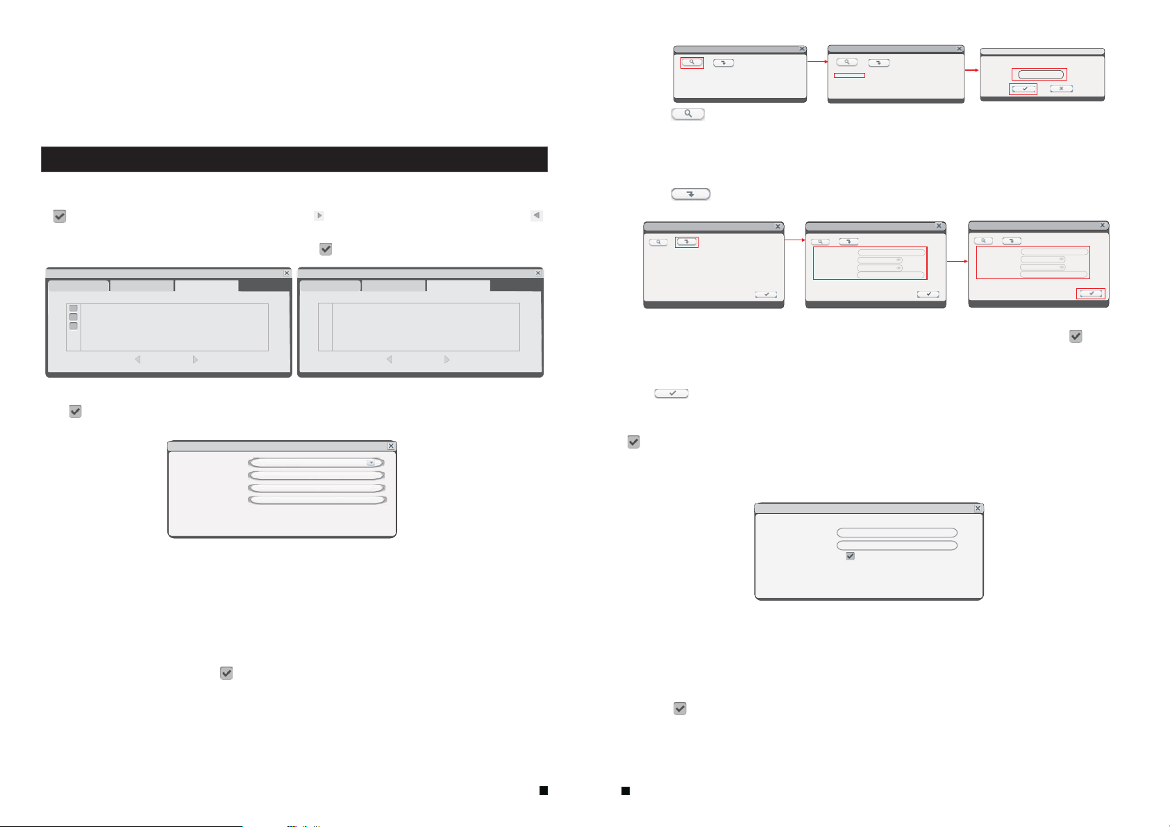
2.4.4 Record Scheduling
Click “Setup”—“Scheduling”(the tab will be highlighted when selected) and single-click to enter
the “Record Scheduling” menu.
represents the hour from midnight-01:00 AM and the last block (below the “23” on the right hand
side of the screen) represents the hour from 11:00 PM-midnight. After setting up the record
schedule, click the “ ” button at the bottom of the screen to save it.
Alternatively, left-click and drag the frames of the boxes in the schedule timeline where you
want to.
Another way to set up schedules is to create a schedule for one day of the week, and then use
the “Copy from” and “to” dropdown menus and “ ” copy button settings to apply the
setting from one day to another day or a series of up to all seven days of the week. To do this,
first create a schedule for one day. Then, from the “Copy from” dropdown menu, select the first
day of the week that the schedule should apply to. Next, from the “to” dropdown menu, select
the last day of the week that the schedule should apply to, and click “ ” copy button. For
example, to set a schedule where the device uses MD recording from 2:00 AM until 1:00 PM,
and normal recording from 1:00 PM until 10:00 PM on Tuesdays, Wednesdays, Thursdays, and
Fridays, the process would be as follows:
Click the orange box at the bottom of the screen to select “MD record.” Then, in the row of
1.
gray box es n ex t to t he “ TUE.” box, click all of b ox es f ro m th e third box from the left t o th e bo x
under the “12” at the top of the timeline(the box directly under the “12” should be selected) in
order to select the hours between 2:00 AM and 1:00 PM.
Click the green box at the bottom of the screen to select “normal record.” Then click all of
2.
the boxes in the same row from the box immediately to the right of the box under the “12” at
the top of the timeline to the third box from the right to select the hours from 1:00 PM-10:00 PM.
The preceding steps set a schedule for Tuesday, which can now be copied to Wednesday,
3.
Thursday, and Friday. To copy it, from the “FROM” field, first select “Tues.”
In the “To” field, select “Fri.” and then click “ ” copy button.
4.
5. To save this schedule, click the “ ” button at the bottom of the screen.
Regardless of whether the schedule is set for each day individually or by copying one schedule
to multiple days of the week, it is necessary activate it by clicking the “ ” button. Without
clicking the “ ” the schedule will not take effect.
2.4.5 Alarm
[Channel]: Users can select channel 3 or channel 4.
There are five modes for recording: “MD”, “Normal”, “None”. Different colors are used to
identify the different recording modes: Orange refers to “MD record”, green refers to “normal
record”, gray refers to “no record”.
To set up weekly schedules, click on the box of the recording status to be used (Alarm, Normal,
or No record) and then click on each box in the schedule timeline that this recording status is to
be applied to. See the “Scheduling” screenshot in the preceding figure. Each gray block
represents one hour on a 24-hour clock, i.e. the first block(next to each day of the week).
Click “Setup”—“Alarm”(the tab will be highlighted when selected) and single-click to enter
the “Alarm” menu to set up motion detection alarm.
Alarm
Motion
Channel 3
Sensitivit y 4
MD area
MD Enable
Record
Push
To enter motion setup, the dialog window where Sensitivity, MD Area, Enable Switch, record
settings and Push Switch can be set will appear.
[Channel]
[Sensitivity]
: In this field, select the channel to be set up.
: Each channel has a specific sensitivity setting; there are eight levels, with “1”
being the highest level of sensitivity; left-clicking to adjust the level.
23
24

[MD Area]
: Sometimes, it is necessary to have some regions in the camera's coverage area
enabled with the motion detection feature, while other regions in the same coverage area do not
require this functionality. This may be handy when, for example, the camera covers the road and
an adjoining area.
While it would be useful to have the motion detection
enabled on the area near the entrance to a building, it
would most likely not be helpful to see it triggered every
time a car or truck passes by on the nearby road. Each
channel has a specific regional motion detecting setting.
Move the cursor to “ ” and then single-click. When
viewing the selected channel's coverage area using the
MD Area option, the blue area is where motion detection
is activated, and transparent block is the area where
motion detection is not activated.
Left-click and drag the frame to set up the region for motion detection.
[MD Enable]:
Each channel has a corresponding channel switch. “ ” indicates that the motion
detection alarm of the selected channel is enabled.
[Record]:
“ ” indicates that the selected channel will record if it has been triggered by motion.
Note: To select the option, please make sure that a SD card has been already inserted
into the video data can be stored onto the SD card normally.
[Push]: “ ”
indicates that a detection information will be pushed to user’s phone if the selected
channel has been triggered by motion.
Note: Please make sure that the indoor monitor and user’s phone are both connected to internet.
2.4.6 Maintenance
Click “Setup”—“Alarm”(the tab will be highlighted when selected) and single-click to enter the
“System Maintenance” menu. Options include “SD Management” and “System Upgrade”.
System maintenance
SD Upgr ade
Size/Free Fr ee time S tatus F ormat
484M/12M 1Min OK
Auto overwrite
2.4.6.1 SD
To enter the “System Maintenance”, select “SD” (see adjacent figure).
SD Upgr ade
Size/Free Fr ee time S tatus F ormat
484M/12M 1Min OK
Auto overwrite
Auto
System maintenance
Auto
[Size/Free]
: This field indicates amount of space available and the amount of unused space
available on the SD card. The capacity of the SD can be used up to 128GB.
[Free Time]
[State]
: Indicates remaining recording time on the SD card.
: There are two available statuses: “OK” and “No SD”.If a new SD card is used with
the device for the first time, please format the SD card.
[Format]
: Move the cursor to select the device to be formatted, “ ” indicates the option of
“format” is enabled, and click “ ” to begin formatting.
[Auto overwrite]
:Options Include “Disable and Auto”. If a user chooses “Disable”, the
recording stops when the SD card is full. Once the SD card is full, it will not record again until
“overwrite” is enabled. If a user chooses “Auto”, recording continues and overwrites previous
recording when the SD card is full.
2.4.6.2 Upgrade
To enter the “ ”, select “upgrade”(see adjacent figure).system Maintenance
System maintenance
SD Upgr ade
System upgrade
Create a new folder called “ ” on a SD card, if its capacity is less than 64GB,
its file system must be , and if its capacity is more than 64GB, its file system must be
ivrupgrade
FAT32
exFAT. Then copy the update file to the folder, and then insert it into SD port of the device. Click
“ ” to upgrade the firmware and it will display the process of the system upgrade.
Note: The system upgrade will require at least two minutes; during this time, do not remove the
SD card or turn the device disable. After completing the upgrade, the device will restart.
2.4.7 User
Click “Setup”—“User”(the tab will be highlighted when selected) and single-click to enter
the “User” menu. In this field, a password for accessing the indoor monitor system can be set or
changed.
“ Login with password” indicates the password is enabled, and user must input the correct
password to login the system.
After the password verification is set up (marked “ ”) theAdministrator can set up to seven
user passwords, as well as anAdministrator password. If the password function is enabled, it
will be necessary to enter the password before logging in.
Note:
Once the password has been enabled, it is necessary to log in to the system as “Admin”
in order to manage users; TheAdministrator's username (“Admin”) cannot be modified.
The default password for is “ ”.
Admin 888888
25
26

Login with password
0
User
-
Admin
+
Modify PSW
Old password
New password
Confirm password
Local
test
Remote
The following settings can only be set by the system administrator (who will be referred to
throughout this manual as “the Administrator”; the username for the system administrator is
“Admin”).
[Add Users]: Click “ ” to add new users. In this window, enter the new user's name and
+
password in the corresponding fields, and then to confirm the password, enter it a second time
in the “Confirm Password” field. The length of the password must not exceed 6 digits. And user
can add se ve n us er s at most. Click “ ” to s ave.
Add user
User name
Password
Confirm password
test
******
******
[Delete Users]: From this window (see the following figure), theAdministrator can delete
users (the color of the user has been selected will be yellow) by selecting the user of the user
account to be deleted.And click “ ” to enter the window to confirm.
-
User
Login with password
0
1
2
3
Admin
test
fly
door
[Local Permission]: This allows theAdministrator to give each user its permission to access
a unique set of indoor monitor functions. That is, the Administrator can give a user access to
one, some, or all of the following functions: Record, Playback, Set parameter, Ring, and
Upgrade/Reboot/Maintenance/Format/Default, and the set of functions that one user is
allowed to access may include functions that are different from the set of functions that
another user is allowed to access (see the below figure).
test
Modify PSW
Operation authority
Record
Playback
Set parameters
Ring
Upgrade/Reboot/Maintenance/Format/Default
Local
Remote
[Remote Permission]: This is a very important function for remote operation of the indoor
monitor. The Administrator can use this function to set each user's remote access permissions,
such as access to Playback/Download and Set Parameters from a computer that is not on the
local network (see the following figure).
test
Modify PSW
Local
Playback/Download
Set Parameters
Remote
-
+
[Modify Password]: Select a user to enter the interface to modify user's password. From this
window, the Administrator can change the system's password. For security reasons, before
a new password can be set, it is necessary to enter the original password.
“ ”indicates that authority is enabled, “ ” indicates that authority is disabled. Click “ ”
to save.
27
28

2.4.8 Default
Click “Setup”—“Default”(the tab will be highlighted when selected) and single-click to enter
the “Restore to default” menu.
The system restores the default configuration status in the factory, and corresponding setting
can be resumed based on options on the menu. User can select “All” to restore all the settings
to the original factory settings. The options include: Time, Color and margin, Record schedule,
User, Maintenance, Network, Network advanced and Alarm setup.
Prompt: The port and language can't be resumed.
Restore to default
All
Time
Color and margin
Record schedule
User
Maintenance
Network
Network advanced
Alarm setup
2.4.9 Information
Click “Setup”—“Information”(the tab will be highlighted when selected) and single-click to enter
the “Device information” menu.
The information included accessible through this interface includes: the device ID, the
software version, the release date.
Device information
Device ID al01105418
Software versio n V3.0.1RW
Release date 2018-07-17
2.4.10 Save/Exit
On the “Configuration” menu, right-click or click “ ” to enter the “Save” menu.
Save
3. Web Browser Operation
3.1 Feature
Install the software through the Internet browser of OS to conveniently operate the network
from a remote location. This device supports C/S, B/S, and access in LAN and WAN. It also
supports IP and domain name visiting.
IMPORTANT! SOFTWARE RECOMMENDATIONS:
To ensure reliable remote viewing of IVR footage, it is highly recommended that users have
either Windows XP, Windows 7 or Windows 8 installed on their computers, and that they use
either Internet Explorer 6.0, Internet Explorer 7.0, Internet Explorer 8.0, Internet Explorer 9.0,
Mozilla Firefox, or Google Chrome as their Internet browser. (In the appendix, there is an
explanation of how to access the indoor unit using Firefox or Google Chrome.)
3.2 Network Security Setting
Prior to setting up remote access, set the network security level by following the following
instructions:
(1) Open the Internet Explorer browser and click the “Tools” tab located in the bar at the top
of the browser; from the drop-down menu, select “Internet Options”.
(2) Click the “Security” tab in the dialogue box
(3) Click “Custom level” (at the bottom of the dialogue box) to set the security level. .
Set the appropriate settings for theActiveX controls and plug-ins. Find the following controls
in the “Security Settings” box and select the “Enable” option for each of them. This is an
extremely important step.
* Automatic prompting forActiveX controls.
* Binary and script behaviors.
* Initialize and scriptActiveX controls not marked as safe for scripting.
* Download signed ActiveX controls.
* Download unsigned ActiveX controls.
* RunActiveX controls and plug-ins.
* ScriptActiveX controls safe for scripting.
Prompt: Before setting up remote access, turn Disable the firewall and any anti-virus software
currently running on the computer.
Save Exit
[Save]
: Save all settings and exit the menu.
[Exit]
: Exit the menu without saving any changes.
29
30

3.3 Connection Settings
Remote access to the IP video door phone is carried out over the Internet. In the local area
network, the IP address of the client-side computer must be in the same network segment that
the IP address of the IP video door phone. In the wide area network, the only requirement is
that the two sides can visit the public network and connect to the Internet through the IP
address or the dynamic domain name. The following will mainly focus on connecting and
setting up the local area network.
: Right-click on “Network Neighborhood” and click “Properties” in the menu to open the
Step 1
“Network Connections” menu. Alternatively, if the operating system being used does not have
a “Network Neighborhood” icon, enter the Control Panel found in the “Start” menu; then, click
“Network and Internet”, and select “Network and Sharing
Center.” On the “Network and Sharing Center” page, there
should be a “Network” section; in that section, there should be
a “View Status” link next to a listing that reads “Connection:
Local Area Connection.” Click the “View Status” link.A small
“Local Area Connection Status” window will appear; at the
bottom of this screen, click “Properties”, and if prompted to
give permission to continue, click “Yes.”
: Double-click to open “Local Area Connection” from the
Step 2
“Network Connections” menu.
: Click “Properties” in the lower-left corner of the window
Step 3
(see preceding figure).
: Double-click “Internet protocol (TCP/IP)” from the “This
Step 4
connection uses the following items” list in the center of the
window (see preceding figure).
is most likely in the same network segment. However, they must not be exactly the same as
the ones on the indoor unit, as this will cause IP address conflicts. Taking the preceding figure
as an example, the IP address should be: 192.168.1.X, where X cannot be 244 or 1 (including
other IP addresses currently being used), and cannot exceed 255, as the subnet mask is
255.255.255.0, and the gateway is 192.168.1.1.
3.4 Control Download and Installation
After the aforementioned settings have been adjusted and saved, open the Internet browser,
enter (192.168.1.X is the set IP address of the indoor unit) and confirm. If
http://192.168.1.X
the http port of indoor unit setting has been changed (if it is not “80”), it will be necessary to
add a “:” followed by a port number. For example, assuming that the current port number is “P”,
enter “ ”, to correct the problem.
http://192.168.1.X:P
After connecting to the internet, Internet Explorer (or other Internet browser being used) will
automatically download the file to the computer as follows. Click “Install”.
The system will automatically enter the GUI as follows.
Step 5
: Examine the IP address, subnet mask, and default gateway on the PC.
Step 6
: Set the corresponding IP address, subnet mask, and default gateway on the indoor
unit(for detailed instructions, refer to ). If the subnet mask and
default gateway on the indoor unit are the same as those of the computer, then the IP address
Section 2.4.2 Network Setup
Select the English interface from the upper left side. Enter the correct password if a password
has been enabled. The password is the same as the one set in indoor unit.
: In this field, enter the username. The default is .[USER ID] Admin
31
32

[PASSWORD]
888888
[NETWORK]
[Open Preview]: “
that user needs to connect all the cameras manually after the login.
Note: If the device is connected to the WAN, the IP address should be a public IP address.
: The password is as the same as the password for the indoor unit. The default is
.
: MAIN STREAM or SUB STREAM.
” enable to view all the cameras automatically after the login. “ ” means
3.5 Operation Interface
Options in the main interface include “LIVE”, “PLAYBACK”, “REMOTE SETTING”, “LOCAL
SETTING” and “LOGOUT.” Click any option to access it.
3.5.1 Live
Click “Live” to enter the interface as follows (in some cases, it will be necessary to click “ ”
to open images from the indoor monitor).
DOOR1
11/10/2016 15:40:50
DOOR2
11/10/2016 15:40:50
3.5.2 Controls
To use the controls, move the cursor over the icons, which will become highlighted
when selected.
Connect all windows or disconnect all windows.
/
Capture images which can be saved in a local disk (the default system save path is
“c:\IVR\Capture\”).
Quick-start to record video on all channels, and the right bottom corner of each channel
has a normal recording video symbol “ ”(the default system save path is
“c:\IVR\Record\”).
Click this button to unlock for the door machine.
Click these icons to switch between the single-screen ( ), quad-split( ) and full-screen
( ) options.
CAM1
The left bottom corner of each individual channel is occupied by camera view tools:
11/10/2016 15:40:50
CAM2 11/10/2016 15:40:50
/ : Connect the current window view or close the current window view.
:Start recording or stop recording of the current channel view. And the right bottom
/
corner of the current channel has a normal recording video symbol “ ”.
:Takes a snapshot of the displayed image.
:Increase or decrease brightness.
:Increase or decrease image contrast.
: This indicates that the channel has detected motion while in motion-detection mode of
the remote indoor unit.
:Unlock for the door machine. Click this button to access the “Unlock” window(shown as
below), input the correct password and click the button “ ” to confirm.
3.5.3 Other Operations
1.2.Select one channel from the preview screen (the color of the selected channel's frame will
change to blue), and double-click the left mouse key will enlarge the current channel view.
And single-click right mouse key as a full-screen display of the selected channel.
Single-click right mouse key on the preview screen will maximize all the current channels to
full-screen. And single-click right mouse key again will back out.
3.5.4 Playback
Click “ ” to enter the playback interface.Playback
33
34

To search for a recording by date, click calendar in the upper-right corner, and use “ ”and
“ ” to set the month of the video being searched for; click “REFRESH” (located just below the
calendar) to display the recording information of current month.
HDD for backup or later viewing. The downloaded file format is “AVI”. The option“ ” on the left
Using this button, users can download files to their computers and save them to a
side of the file is available for downloading. “ ” indicates the file will be saved to a HDD after
clicking the “ ” button.
3.5.5 Toolbar Guide
Play status bar
Volume Control
The highlighted date indicates the recording date of the video being played. Click on a date to
view the recording file list for that day. For example, the preceding figure shows that there are
videos on file that were recorded on November 5 and 7 (indicated by the numbers being in
bold print), and is the recording file list that is currently open is the list of videos recorded on
November 5 (indicated by the darker background and the “5” in white text).
th
th th
Another way to find a video is to select the channel and type of the file in question from the file
list below the calendar. After selecting the channel and type from their respective drop-down
menus at the top of the file list, click “SEARCH” and the results will be displayed in a list like the
one in the following figure.
Double-click one of the listed recorded videos or select one of the listed recorded videos and
then click “PLAY” to begin playback.
CAM2
11/05/2013 11:15:05
Play Pause Stop Fast play Snap E-zoom
Slow Play
Single Frame
Download status bar
The starting time and the ending time of the current downloading file
3.5.6 Remote Setings
Click “Remote Setting” to enter the “Remote Setting” setup menu. This interface includes
record setting, alarm setting, network setting, advanced setting, system info, remote upgrade
and user modify, which can all be modified remotely through an Internet browser.
A.Record Settings
In the sidebar on the left, click “Record Setting” to enter the recording settings menu. From this
page, users can enable or disable recording for channel 3 or channel 4, set recording schedules,
and adjust specific recording parameters, i.e. enabling/disabling record, and setting recording
modes.
B. Alarm Settings
From the sidebar on the left, click “Alarm Setting”, then select “ChannelAlarm” to enter the
“Channel Alarm” setup interface. From this interface, users can set motion-detection alarms,
define motion-detection privacy masking areas, motion sensitivity, and motion alarm push.
35
36

C. Network Settings
From the sidebar on the left, click “Network Setting”, and then select “Network” to enter the
network settings interface. The menu allows users to set basic attribute and DDNS setup.
D. Mobile Settings
From the sidebar on the left, click “Network Setting”, and then select “Mobile” to enter the
“Mobile Settings” interface. From this page, users can set ports, push switch and push time.
G. System Info
[Version Information]: From the sidebar on the left, click “System INFO”, and then select
“Version INFO” to enter the system information interface. Here, users can find out the device
name, software version, and the release date.
H. REMOTE UPGRADE
From the sidebar on the left, click “REMOTE UPGRADE” to enter the remote upgrade interface.
Clicking “ ” will select file for upgrading. Then click the “ ” remote upgrade
button in the center of the screen.
E. IP Firewall
From the sidebar on the left, click “Network Setting”, and then select ”IP Firewall” to enter the
firewall settings interface. From this page, users can turn the firewall on or Disable for specific
IP addresses.
F. System Setting
From the sidebar on the left, click “Advanced Setting”, then select “System Setting” to enter
the system settings menu. From this menu users can find out the language and TV mode for the
indoor unit.
37
I. User Management
[ADD or DEL]: From the sidebar on the left, click “User Manager”, and then select “Add or Del”
to enter the add user or delete user interface. The administrator can add new users or deleted an
added user.
[Modify password]: From the sidebar on the left, click “User Manager”, and then select “Modify
password” to enter the user management interface. Users can modify the user’s password.
38

3.5.7 Local Setings
From the sidebar on the top, click “Local Setting” to enter the local settings interface. From this
page, users can set up the save path for local settings; in the “Record Save Path” field, they can
create a save path for recordings, in the “Picture Save Path” field, they can create a save path
for video/still images, and in the “File Save Path” they can create a save path for downloads.
Clicking “ ” will set up the respective save path.
3.5.8 logout
Click “Logout” to log out of the system.
4. Mobile Phone Software Visit
This IP video door phone can transmit live feed to your mobile phone, so that you can have 'on
the go' access to your surveillance system from virtually anywhere. To view, you must install a
mobile operating system specific program into your mobile. Currently, there are a limited
number of phones that are supported: Google Android and Apple iPhone or iPad. TheAndroid
mobile program is located on the included CD or downloaded via “Play Store”, and an iPhone
mobile program or an iPad program is downloaded via “APP Store”. In “APP Store” or “Play
Store”, please search for “MobileEyeDoor+”. Please see the instruction manual for your mobile
to install the program.
4.1 Iphone Mobile or Ipad
The Apple iPhone or iPad application, like all iPhone or iPad applications, needs to be
downloaded directly from the App Store. Open APP store, search for “MobileEyeDoor+”, it's a
free application.
1
))Through the indoor unit connection to network (or PC), and then to the indoor unit electric
start.
Note: The default IP type of the indoor monitor is DHCP, for the first time PC and the
device must be connected to the same router.
2 uCareHome
Login the app “ ”, make sure that your smart-phone and the device are
connected to the same WIFI network, press “Door Intercom Monitor”-> “Connect New
Device” -> “Existing”, and press “Confirm”.
IST View
IST View
IST View
2.
Press “LAN Search”:
Online devices which are connected to the same WiFi router will be shown on the list(as below):
Device UID
Device IP address on LAN
2.
User can access to the indoor monitor by this device IP address on LAN on PC.
For more information about the 'IST View' app, please refer to the operation manual
NOTE: More information about the “uCareHome” pls check the user manul of it.
39
40

Appendix 1. Accessing the indoor unit via Mozilla Firefox
1.
First, install Firefox on Windows(This document will use Firefox 3.6 as an example )
2.
After installing Firefox, search for the “IE TAB” add-on for Firefox; this file is named
“ie_tab_plus-1.95.20100930-fx+sm (IE Tab Plus (FF 3.6+).xpi”. (This file can be downloaded
from the Mozilla website)
3
To install: Open Firefox, then click “Tools”, and select “Privacy” and a dialog box will appear.
.
Then choose tab which is named “Get Accessory Discreteness”, and copy and paste
“ie_tab_plus-1.95.20100930-fx+sm (IE Tab Plus (FF 3.6+).xpi” into the address field. A dialog
box will prompt you to install or cancel the program; choose “Install immediately.” After installing
the program, restart Firefox Browser.
4.
Open Firefox and enter the indoor unit IP address in the address field.
5
Right-click at blank, select “Use IE TAB Plus to play this Page”, and choose “Switch browser
.
engine”. The indoor unit can now be connected successfully.
Appendix 2. Accessing the indoor unit via Google Chrome
.First, install Google Chrome on Windows(this manual will use Chrome version 7.0.517.36 as
1
an example ).
2.
After installing Google Chrome, search for the “IE TAB” Chrome add-on; this file is named
“extension_1_4_30_4.crx”. (This file can be downloaded from the Chrome Web Store)
3.
Open Chrome, enter the IP address of the indoor unit into address bar, and the following screen
will appear.
5. Select “Allow” to download multiple files and the following screen will appear.
6. Select “Continue” to continue installing extensions and the following screen will appear.
7. Click “Install” and the following screen will appear.
4. Drag the add-on into the browser interface and the following screen will appear.
Note: If the web page still does not open, press the “ icon on the right of the address field
to display this page in an IE based-tab.
Fill in the correct user name and password to log in.
8.
”
Appendix 3 Remote Control Optional).(
Pressing the “enter” key on the remote control of the device has the same function as
left-clicking a computer mouse.
Stop Press this button to stop playback.
(■):
Play/Pause ( Pressing this button opens the video search function and the playback menu.
When the playback mode is activated, press this button to play/pause playback.
( ):Move selected item in menu.
41
42
):

Menu (MENU/ESC): Press this button to access the toolbar, hide the toolbar, enter or exit from
the menu, and enter or exit sub-menus.
Numerical Buttons: Using these buttons, you can choose to display video on your monitor either
as a full-screen view of each of the cameras individually (Channels 1 through 2).
ENTER: This button is used as the “enter” key in most circumstances (i.e. for selecting items from
a menu).
Spot View ( ): Press this button to enable auto sequencing, and press any other button to
interrupt sequencing.
Quad ( ):Press this button to switch display modes.
●
):
REC ( Press this button to start or stop manual recording.
Appendix 4 How to ensure reliable remote viewing of the
indoor device through IE browser on Win 7/Win 8 64bit OS
1. Run 32bit IE on Windows OS (64bit)
Note: On a 64-bit version of a Windows operating system, there are two versions of the
Internet Explorer files:
*
The 64-bit version is “C:\Program Files\ Internet Explorer \iexplore.exe”.
*
The 32-bit version is “C:\Program Files(x86) \ Internet Explorer \iexplore.exe”.
*
Please run the 32-bit version “C:\Program Files(x86) \Internet Explorer \iexplore.exe”.
2. Run Internet Explorer as the Administrator
1)
Open folder path “C:\Program Files(x86) \Internet Explorer”.
2) Run as Administrator
Right click the Internet Explorer icon and choose " ".
3)
Click "Continue" in the User Account Control window to grant administrator access to
Internet Explorer.
3.Fix site display problems with Compatibility View
Sometimes a website you're visiting doesn't look like you expect it to. Images might not show
up, menus might be out of place, and text boxes could be jumbled together. This can be caused
by a compatibility problem between Internet Explorer and the site you're on. When a site is
incompatible with Internet Explorer, you'll see the Compatibility View button in the Address
bar. You can only turn on Compatibility View in Internet Explorer for the desktop.
A. To turn on Compatibility View
1)
See if the Compatibility View button appears in the Address bar. (If you don't see the
button, there's no need to turn on Compatibility View.)
2)
Tap or click the Compatibility View button to display the site in Compatibility View.
Once you turn on Compatibility View, Internet Explorer will automatically show that site in
Compatibility View each time you visit. You can turn it off by tapping or clicking the button
again. Or, you can clear the entire list of sites using Compatibility View by deleting your
browsing history.
B. To clear the list of Compatibility View sites
Not all website display problems are caused by browser incompatibility. Interrupted Internet
connections, heavy traffic, or problems with the website can also affect how a page is
displayed. If you're having other problems on a site, such as playing videos, read Video
won't play in Internet Explorer.
The Compatibility List is frequently updated, and Internet Explorer automatically downloads
these update. This list includes sites that might've been designed for older or other browsers,
sites that use Adobe Flash Player, and other settings that help give you a better browsing
experience. If you don't want these updates, you can turn off Compatibility List Updates at
any time.
C. To turn off Compatibility List Updates
Open Internet Explorer in the desktop.
1)
Press theAlt key to display the Menu bar (or press and hold theAddress bar and then select
2)
Menu bar).
Tap or click Tools, and then tap or click Compatibility View settings.
3)
Clear the Download updated compatibility lists from Microsoft check box, and then tap or
4)
click Close.
D. To change Compatibility View settings
Open Internet Explorer in the desktop.
1)
Press theAlt key to display the Menu bar (or press and hold theAddress bar and then select
2)
Menu bar).
Tap or click Tools, and then tap or click Compatibility View settings.
3)
43
44
 Loading...