


OPERATION INSTRUCTIONS
V500 (Slave) Video Monitor
not
*Does
work as a standalone master*
Quick Guide

Return to Stock to Stock
CARING FOR THE ENVIRONMENT BY RECYCLING
Product returns require a Return MerchandiseAuthorization Number(RMA). Please call
customer service at 877-435-0670 to receive your RMAnumber, BEFORE returning any
merchandise. Any product returned without an RMA number is subject of being refused and
returned to customer. Once received Intrasonic Technology will evaluate the returned items
for damaged and completeness.A credit memo will be issued to the customer once the
product has been evaluated.Any damaged or missing items will be deducted from the amount
credited. Return to stock items must be in unopened original boxes and in like new condition.
Credit will not be issued for used or previously installed product.All returns are subject to a
10% restocking charge.
Intrasonic Technology 2 Year Limited Warranty
Intrasonic Technology warrants its products to be free of manufacture defects for 2 years of
closing or actual installation. This warranty only applies to products purchased from authorized
dealers or distributors. If proof of installation cannot be supplied the manufactures serial
number or date code will be substituted. This warranty extends to the original user or subsequent
owner of the product during the warranty term. Intrasonic Technology will replace or repair
the product at its discretion at no charge with a reconditioned or new product.All products
with manufactured defects must be returned to Intrasonic Technology, Inc.
If an Intrasonic Technology product is determined to have a manufactures defect, please call
our toll free number (877-435-0670) before any attempt to dismantle the product. Any attempts
to dismantle the product will void the warranty.
An RMA (Returned Material Authorization) will be required prior to returning a product
to Intrasonic Technology, Inc. To obtain an RMA call our toll free number (877-435-0670) and
speak with a customer service representative. All products returned to Intrasonic Technology
without an RMA will be refused.
Intrasonic Technology will not be liable for consequential, incidental or damages arising in
connection with use or inability to use this product. In no event shall Intrasonic Technology
liability hereunder exceed the cost of the product covered hereby. No person is authorized
to assume for us or obligate us for any other liability in connection with thesale of this product.
Some states do not allow the exclusion or limitation of consequential, incidental or damages,
so the above limitation or exclusion may not apply. This limited warranty gives you specific legal
rights, and you may also have other rights, which may vary state to state.
When you see this symbol on a product, do not dispose of the
product with residential or commercial waste.
Recycling your electrical equipment
Please do not dispose of this product with your residential or commercial waste. Some countries or
regions, such as the European Union, have set up systems to collect and recycle electrical and
electronic waste items. Contact your local authorities for information about practices established for
your region.
COPYRIGHT STATEMENT
All rights reserved. No part of this publication may be reproduced in any form or by any means,
anscribed, translated into any language or computer language, transformed in any other way,
tr
st
ored in a retrieval system, or transmitted in any form or by any means, electronic, mechanical,
recording, photocopying or otherwise, without the prior written permission of the owner.
Video Intercom
Warrants its products for two years of closing or actual installation. This warranty only applies
to products purchased from authorized dealers or distributors. If proof of installation cannot be
supplied the manufacture serial number or date code will be substituted. This warranty extends
to the original user or subsequent owner of the product during the warranty term. Intrasonic
Technology will replace or repair the product at its discretion at no charge with a reconditioned
or new product. All products with manufactured defects must be returned to Intrasonic
Technology, Inc.
1
2
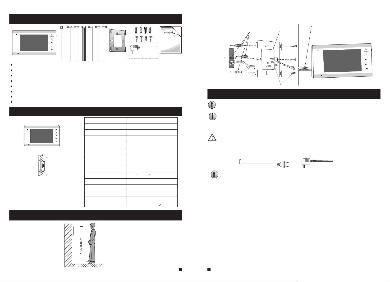
Accessories
1
2
Monitoring
Talk
Unlock
Hang up
(Optional)
Indoor monitor --------------------------------------------------------------------------------- 1pcs
Screw anchors --------------------------------------------------------------------------------- 4pcs
Wall screws ---------------------------------------------------------------------------------- 4pcs
Bracket ------------------------------------------------------------------------------------------ 1pcs
4 Pin line --------------------------------------------------------------------------------------- 6pcs
2 Pin line --------------------------------------------------------------------------------------- 1pcs
User manual ----------------------------------------------------------------------------------- 1pcs
External switching power supply DC 12V(optional, please check actual model)------1pcs
Specification
236mm
1
2
19mm
Monitoring
Talk
Unlock
Hang up
Display screen
Definition
Standard
Calling mode
Calling time
Standby current
Work current
143mm
TF
Power supply
Work temperature
Installation way
Built- in storage
Picture format
Extension memory
7"TFT LCD screen
800(H)X480(V)
PAL/NTSC
Two-way conversation
120s
Maximum 200MA
Maximum 500MA
Built-in power supply- -option al
External switching pow er
supply(DC12V)--opt ional
-10 C~+60 C
Surface mounting
Yes
JPEG standard format
SD card
(maximum 32GB)(>CIass 10)
How to install the indoor monitor?
cables
Screw anchors
Bracket
1
2
Wall screws
NOTE ON WIRING CONNECTION
The electric lock/source/camera is not include in the package, you can purchase an electric lock that
is suitable for your needs.
A standard
unlocking methods. This means that in the normal state the dry contact is opened so
the lock is kept under constant closed state. If the unlocking push-button is pressed
and the dry contact is changed to closed, then the lock is released.
The indoor monitor with a built-in power supply or an external switching power supply
is optional, please refer to the manufacturer. The device with a built-in power supply
is applicable to wide voltage range(AC 100V~240V). Please first pull out the AC
power plug before installation of the device(shown below).
Please note the silk printing marked on PCB in order to avoid incorrect connecting.
The wiring connection :requirement
1. 4C ordinary non-STP wiring cable;
2. rom the outdoor camera to furthest indoor monitor:Effective distance f
Transmission ≤28m (4x0.2mm )
Transmission ≤50m (4x0.3mm )
Transmission ≤80m (4x0.5mm )
relay mechanism supports locks with Normally Open (N.O.) door
2
2
2
Monitoring
alk
T
Unlock
Hang up
Install the indoor monitor
3
4
Wiring connection according to the following to avoid interference:
Power+ Video
Audio
GND
Power+ Video
GND
Audio
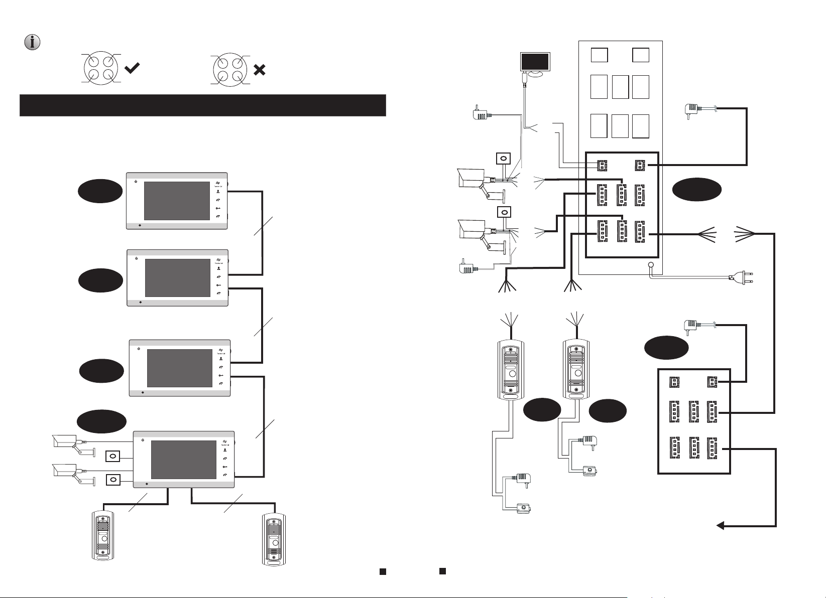
WIRING DIAGRAM
MUST ACTIVATE AS 'SLAVE'
MONITOR IN MODE SETTINGS!!!
1
Slave
Slave
Slave
2
1
2
1
2
Monitorin
g
Talk
Unlock
Hang
up
4
C
Monitorin
g
Talk
Unlock
Hang
up
4
C
Monitorin
g
Talk
Unlock
Hang
up
DOOR2
AC/DC power
adapter for
camera
(not included )
CA M1
CA M2
AC/DC power
adapter for
camera
(not included )
ALM1
V
2
1
C
D
DC12V
ALM2
DC12V
o
D
i
d
N
u
G
A
AL
GND
Video
ALM
GND
deo
Vi
o
e
d
i
V
VCC
ALM
GND
VID EO
CAM 1 IN
VCC
ALM
GND
VID EO
CAM 2
GND
12V
DC- IN
AUD IO
GND
DATA
VID EO
AUD IO
GND
DATA
VID EO
OUT
Pow er
External switching power supply
(DC 12V)--opt ional
TV
GND
TV-o ut
VCC
AUD IO
GND
VID EO
DOO R1
VCC
TV
GND
M
AUD IO
GND
VID EO
DOO R2
TV-o ut
Master
IN
CAM 1
DOO R1
AUD IO
GND
DATA
CAM 2
DOO R2
o
o
D
V
i
e
2
d
N
d
1
i
u
G
V
C
A
D
OUT
Buil t- in po we r su ppl y
(AC 100 V~ 240 V)
External switching power supply
(DC 12V)--optional
VID EO
Slave
TV-o ut
DC- IN
CAM2
CAM1
Master
ALAR
M
ALAR
M
DOOR
1
1
2
4
C
Monitorin
g
Talk
Unlock
Hang
up
DOOR
2
4
C
4
C
DOOR1
AC/DC power
adapter
for unlocking
(not included )
DOOR2
AC/DC power
adapter
for unlocking
(not included )
AC/DC
DOO R1
DOO R2
CAM 1
CAM 2
IN
OUT
electric lock
(not included )
AC/DC
electric lock
next Slave
(not included )
Note: F or the i ndoo r moni tor wi th bui lt-i n power supply, the cameras must use
an exte rnal p ower s uppl y.
5
6

DESCRIPTION ON INDOOR MONITOR
1
Monitoring
Unlock
Hang up
6
7
8
Talk
9
10
2
1
2
3
4
5
11
13
11
12
NO.
12
Name
Speaker
Sound from outdoor camera.
Descriptions
For the models with SD card: insert the SD card for recording and pictures
(supports up to 32GB). Recoding files will be stored in the SD card, photographs
TF card slot
13
will be stored in the flash of the indoor monitor memory (on board). If the more
than 20 pictures are saved to flash memory, those pictures will be backed-up to
TF
the SD card automatically when the indoor monitor is in standby mode.
10
11
Name
Power LED, the power indicator of the indoor monitor.
1
2
TFT display
Microphone
Transfer call
Monitoring
8
9
Talk
Unlock
Hang up
The do or 1 st ate l igh ts, t o doo r 1 wor kin g whe n the L ED is o n.
The do or 2 st ate l igh ts, t o doo r 2 wor kin g whe n the L ED is o n.
View visitor’s image displayed on the TFT screen.
Transmit the voice to outdoor camera.
Intercom call or transfer calls to another indoor monitor.
Watch the door and camera images.
Activate conversation mode by pressing this button
Release the door lock.
Hang up
1. The button is a composite key, users can press the button,
scroll the button upward or downward. For more details,
please refer to the section “Menu Operations”.
2. In standby mode, press the button “ ” once to quickly
access the menu.
Setting
In main menu settings, scroll the button “ ” upwards or
3.
downwards to select sub-menu, then press “ ” again to
enter sub-menu. In sub-menu settings, press “ ” to select
menu options, scroll “ ” upwards or downwards to adjust
values of each option, then press “ ” to confirm. When
select option “Return” on the main menu, press “ ” to exit
menu interface, and the indoor device will be into standby
Descriptions
OPERATION INTRODUCTION
VISITOR CALL
Standby mode
The Visitor press
the call button on
outdoor camera 1
10s of continuous ringing
tone is heard inside and
outside
The visitor’s image
automatically displayed on
the screen
Press the talk
button on indoor
Talk
monitor
Stop ringing
Start conversation
with outdoor camera
The co nve rsa tio n
dura tio n is 12 0s
at a tim e
Press the unlock
button on indoor
monitor
The indoor unit will automatically go into standby mode if you are not
at home or have not reached the indoor unit in 60s.
release the
door lock
The Visitor press
the call button on
outdoor camera 2
NOTICE:
Press the hang up button
on indoor monitor
Hang up
End
mode.
7
8
Both the visitor's voice and image will continue to display for 20 seconds after the door has been
unlocked. This is to ensure successful entry.
For the models with SD card (when the doorbell starts recording): From the
start of a call, the
whole process will be recording. When the doorbell records for the snapshot mode, the first
picture will be captured onto the built-in storage of the device
In the monitoring state, the device can listen to the sound of the outdoor bell. The user can press
the button “ ” to converse and press the button “ ” to unlock.
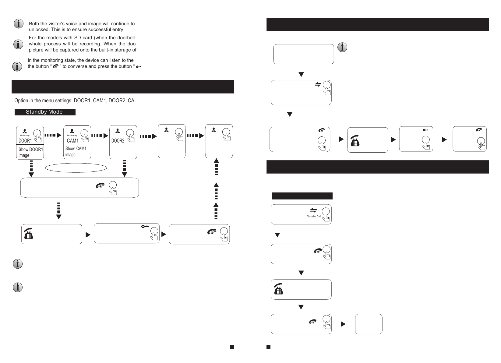
MONITORING
Option in the menu settings: DOOR1, CAM1, DOOR2, CAM2 operating mode (open or closed)
Standby Mode
Monitoring
DOOR1
Show DOOR1
image
Monitoring
CAM1
Show CAM1
image
Monitoring
DOOR2
Show DOOR2
image
Monitoring
CAM2
Show CAM2
image
Monitoring
Standby
Close LCD
CALL TRANSFER TO OTHER EXTENSION
转呼功能
Internal communication function requires at least two indoor and one outdoor units to be connected.
Outdoor camera call indoor
monitor and conversation
is underway
NOTICE:
When you are transferring a call to other extension, the original
conversation indoor unit will return to standby mode, and the
indoor unit which the call is being transferred will also sound a
continuous Ding Dong tone and the video image will appear on
Press this button
its screen.
to activate the function
of call transfer to
other extension
A continuous
ringing tone is
heard
Press the talk
button on any
indoor unit
Talk
Talking
with visitor
The Electric
lock can
be opened
Unlock
End the call
and return to
standby mode.
Hang up
Each monitoring time is 60S
Press the call button
Talk
Call Outdoor
Press the unlock
button on the indoor unit,
Unlock
the electric lock will be opened.
Press the
hang up button
to end the call
Hang up
NOTICE:
If you are using only one outdoor camera in monitoring mode, you can also end the
monitoring mode by pressing the monitoring button again(Must be Close CAM1;
DOOR2; CAM2 in the menu option).
If a conversation with outdoor unit is underway in monitoring mode, a visitor can press the
call button on either of outdoor units and the monitoring mode will be switched off. The
visitor’s image will
are using the indoor unit with hands-free, you can press the talking button to reactivate
conversation with the visitor.
then appear on its screen and continuous ringing will be heard. If you
INTERNAL COMMUNICATION AMONG INDOOR UNITS
At least 2 indoor units are required.
Standby Mode
Press the
Transfer Call
button
A continuous
ringing tone is
heard
Press the talk
button on any
indoor unit
Start conversation
among indoor units.
Press Hang
up button
Hang up
Talk
End
9
10
MENU OPERATIONS
NOTICE:
The button “ ” is a three-in-one key, but also composite keys:
In standby mode, press the b utton “ ” onc e to enter th e main menu settings. In main
menu settings, scroll th e button “ ” up wards or downwards to select sub-m enu, then
press “ ” again to enter sub-menu. In sub -menu settings, press “ ” to select menu
TF
options, scroll “ ” upwards or downwa rds to adjust values of each option, t hen press
“ ” to confirm. When select option “Ret urn” on mai n menu, press the button “ ” to exit
menu interface, and the in door devi ce will be into standby mode.
If users don’t do any operations or enter any interface on the indoor unit, the indoor device will go into
standby mode after 1 minute automatically.
In standby mode _ press the button “ ” to access the main menu interface ( to show the main
interface as shown below). On menus _ scroll “ ” upwards or downwards to move the cursor to the
option “Return”, and then press _“ ” to exit.
System Ring Mode
Alarm Color Files
Return
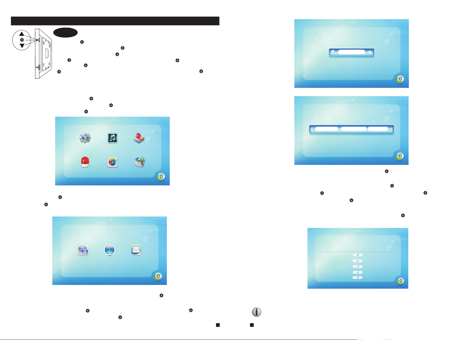
1. Set System Parameters
Scroll the button “ ” upwards or downwards to move the cursor to the option “System”,
then press “ ” to enter the “System” menu. System setup includes: “Language”,
“Time” and “Information”.
English
Return
1.2 System – Time
YY-MM-DD 2016 -04-19 15 :05
Return
On system menu, move the cursor to “Time” and press “ ” to enter the “Time” menu.
Use this field to switch the date format, include “YY-MM-DD”, “DD-MM-YY” and
“MM-DD-YY”, to adjust system date and time. First
move the cursor, and p
ress “ ” to select menu options, and then scroll “ ” upwards or
scroll “ ” upwards or downwards to
downwards to adjust values, then press “ ” again to confirm.
1.3 System – Information
On system menu, move the cursor to “Information” and press “ ” to enter the
“Information” menu. The information includes software version and release date.
Language Time Information
Return
1.1 System – Language
On system menu, move the cursor to “Language” and press “ ” to enter the
“Language” menu. Use this field to change the language of the machine menu text and
the on-screen display. Press “ ” to select menu options, and then scroll “ ” upwards
or downwards to adjust values, then press “ ” again to confirm.
Softw are ve rsio n: 2.1 .2.0
Relea se dat e: 201 6-04 -01
Forma t SD
Forma t flas h
Backu p pict ures
Updat e
Reboo t
Retur n
[Format SD]: This option is for the models with SD card. Format SD card,
please format SD card firstly before using.
Note: The product only supports those SD cards more than Class10.
11
12

[Format flash]: This option is to format built-in storage of the indoor monitor.
[Backup pictures]: For the models with SD card _ backup the photos on the built-in
storage device to SD card manually, and the photos stored on the
device will be deleted. The photos that backup onto the SD card
need to be viewed on PC. (Plug SD card into PC to view)
[Update]: For the models with SD card, users can upgrade the firmware of the device
via SD card.
Note: During the system upgrading, don’t remove the SD card or turn the indoor
device off. After completing the upgrade, the device will restart.
Reboot]: Move the cursor to “ ”, and press “ ”. It will pop-up a window, choose
[
“Yes” to restart the machine, choose “NO” to cancel.
[Return]: Exit the current menu.
2. Set the tone parameters
On main menu, move the cursor to the option “Ring”, then press “ ” to enter the
“Ring” menu. Ring setup includes: “Ring select” and “Ring volume”.
Ring select Ring volume
Return
2.1 Ring – Ring select
On ring menu, move the cursor to “Ring select” and press “ ” to enter the “Ring select”
menu to set up the doorbell tone of the outdoor camera.
Door1 12
Door2 01
Return
[Door1]: To set up the doorbell tone of the outdoor camera 1 (total of 12).
[Door2]: To set up the doorbell tone of the outdoor camera 2 (a total of 12).
[Return]: Exit the current menu.
2.2 Ring – Ring volume
On ring menu, move the cursor to “Ring volume” and press “ ” to enter the “Ring
volume” menu to set up the ring volume. Users can set up different ring volume during
three different time period, the vibrate and ring time can be adjusted from 10s to 45s
when calling.
[Ring Vol1]: the volume level of Ring Vol1: 00-10.
[Ring Vol2]: the volume level of Ring Vol2: 00-10.
[Ring Vol3]: the volume level of Ring Vol3: 00-10.
Ring vol1: 06:00~12:00 0 9 30s
Ring vol2: 12:00~18:00 0 8 30s
Ring vol3: 18:00~06:00 0 7 30s
Return
3. Set the mode of the indoor monitor
On main menu, move the cursor to the option “Mode”, then press “ ” to enter the
“Mode” menu.
Mode: Master
Door2 status: On
Record mode: Snapshot
Door1 unlock time: 02 Second
Door2 unlock time: 02 Second
Return
[Mode]: Options include “Master” and “Slave”. “Master” indicates that the indoor unit
connects the outdoors or cameras, “Slave” indicates that the indoor unit
connects the main or sub indoor unit.
[Door2 status]: Enable or disable the preview of Door2.
[Record mode]: For the models with SD card, options include “Record” and “Snapshot”.
“Record” indicates that the device with SD card will start record
automatically when a visitor press the call button on the outdoor
camera. “Snapshot” indicates that the device will capture a frame of
the video stream as a still photo if a visitor press the call button on the
outdoor camera.
[Door1 Unlock Time]: From 02 seconds to 10 seconds.
[Door2 unlock time]: From 02 seconds to 10 second.
13
14
[Return]: Exit the current menu.
4. Set the alarm parameters
On main menu, move the cursor to the option “Alarm”, then press “ ” to enter the
“Alarm” menu.
CAM 1 Sensor type: NO
CAM 2 Sensor type: NO
CAM 1: Enable
CAM 2: Enable
CAM 1 ring time: 00
CAM 2 ring time: 00
Alarm record: Record
Return
[CAM 1 Sensor type or CAM 2 Sensor type]:
Each camera channel corresponds to
an I/O status (see the following status explanations), which means that when an alarm
is triggered, it will activate the corresponding channel to start alarm recording or
capture a snapshot.
I/O status types:
NO: “Normally open” means that in its normal state, the sensor is kept under
constant low voltage. If the output voltage changes from low to high, then the
alarm will be triggered.
NC: “Normally closed”, the normal state of the sensor is under constant high voltage.
If the output voltage changes from high to low, then the alarm will be triggered.
Disable: Set the sensor type to “Close”, if external sensor alarms are not in use.
[
CAM1]: Enable or disable the preview of camera 1.
[CAM2]: Enable or disable the preview of camera 2.
[CAM 1 ring time]: The alarm ring time of camera 1, if camera 1 has been triggered by
activity, (detected by the sensor) and the values can be set from
0~30 seconds.
[CAM 2 ring time]: The alarm ring time of camera 2, if camera 2 has been triggered by
activity
, (detected by the sensor) and the values can be set
from 0~30 seconds.
[Alarm record]: Options include “Record” and “Snapshot”. “Record” indicates that
when an alarm is triggered, it will activate the corresponding channel
to start alarm recording. “Snapshot” indicates that when an alarm is
triggered, it will activate the corresponding channel to capture a
picture of the current video stream as a still photo.
[Return]: Exit the current menu.
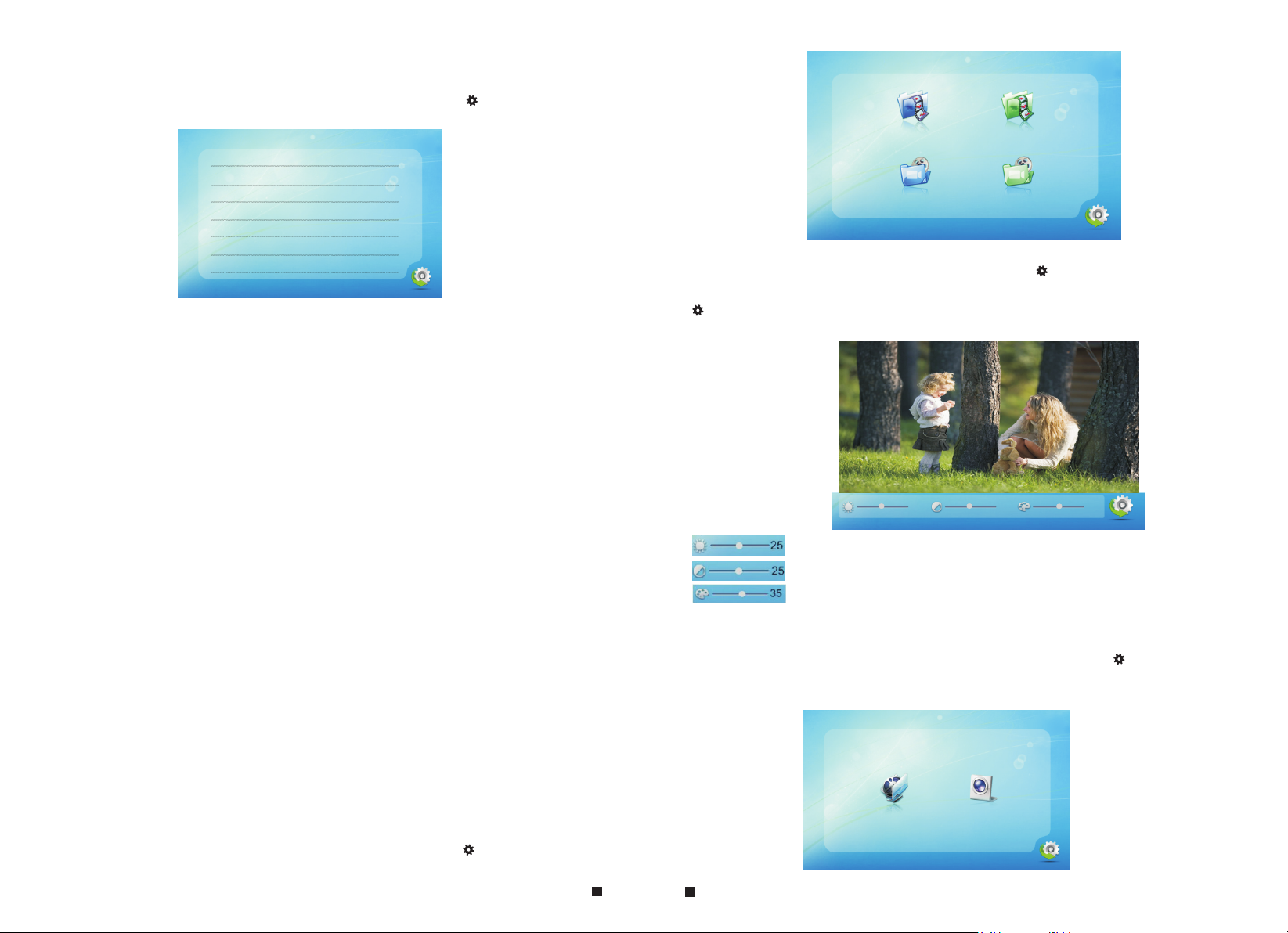
5. Set the color parameters
On main menu, move the cursor to the option “Color”, then press “ ” to enter the
“color” menu.
Door1
CAM1
Door2
CAM2
Return
On the color menu, the video color of Door1/Door2/CAM1/CAM2 attributes can be
adjusted for the best image quality. Scroll the button “ ” upwards or downwards to
move the cursor to the option “Door1” or “Door2” or “CAM1” or “CAM2”, then press
“ ” to enter the corresponding menu to adjust values of brightness, contrast and
chrome depending on the actual conditions.
25
25
35
Return
Brightness, values can be set up from 0 to 50, default as 25.
Contrast, values can be set up from 0 to 50, default as 25.
Chroma, values can be set up from 0 to 50, default as 35.
[Return]: Exit the current menu.
6. Playback
On main menu, move the cursor to the option “Files”, then press “ ” to enter the
“Files” menu. For the models with SD card, options include “Record files” and
“Snapshot files”.
Recor d file s Snap shot f iles
Retur n
15
16

6.1 Files – Record files
On “Files” menu scroll the button “ ” upwards or downwards to move the cursor to the
option “Record Files”, press the button “ ” to enter the “record files list”. Scroll the
button to move the cursor to select file to playback. A red list indicates that the
list has been selected _ press the button “ ”, some tips “Play”, “Delete current file” and
“Delete all file” will appear on the right side of the screen. Select “Play” to play back the
current
file, select “Delete current file” to delete the selected file,
and select “Delete all file” to delete all the files stored on the SD card.
During playback press the “ ”, it will switch the current video to the last file or the next
file, and press the button “ ” again to exit. Move the cursor to the option “Return” and
press “ ” to exit the current menu.
Alarm Instructions
CAM1 and CAM2 of this production have each an alarm function. When the trigger
terminal and GND is shorted, the alarm is activate, the speaker of the indoor unit rings
and continues 120s, during this time, click “ ” t
standby mode.
For the models with SD card, the monitor triggers recording or snapshotting
tive to the system settings). The recording time is 120s, during this time, click “ ”
(rela
to stop alarming and enter the standby mode.
Connection diagram:
o stop alarming and enter the
Hang up
Hang up
201604 11 - 15241 3 0005
201604 11 - 15240 3 0004
201604 11 - 14295 7 0003
201604 11 - 142911 000 2
201604 11 - 14265 1 0001
001 / 001
Return
201604 11 - 15241 3 0005
201604 11 - 15240 3 0004
201604 11 - 14295 7 0003
201604 11 - 142911 000 2
201604 11 - 14265 1 0001
001 / 001
Play
Delet e curr ent fil e
Delet e all fi le
Return
6.2 Files – Snapshot files
On “Files” menu scroll the button “ ” upwards or downwards to move the cursor to the
option “Snapshot Files”, press the button “ ” to enter the “snapshot files list”. Scroll the
button to move the cursor to select file to playback, a red list indicates that the list has
been selected, press the button “ ”,
some tips “Play”, “Delete current file” and “Delete
all file” will appear on the right side of the screen. Select “Play” to play back the current
file, select “Delete current file” to delete the selected file whether or not, and select
“Delete all file” to delete all the files stored on the SD card whether or not.
During
playback scroll the button “ ”, it will switch the current video to the last file or the next
file, and press the button “ ” again to exit.
press “ ” to exit the current menu.
20160 411 - 15241 9 0010
20160 411 - 15241 8 0009
20160 411 - 15240 2 0008
20160 411 - 15240 0 0007
20160 411 - 14300 1 0006
20160 411 - 14295 4 0005
20160 411 - 14292 5 0004
20160 411 - 14292 4 0003
20160 411 - 14283 9 0002
20160 411 - 14272 0 0001
001 / 002
Move the cursor to the option “Return” and
20160 411 - 15241 9 0010
20160 411 - 15241 8 0009
20160 411 - 15240 2 0008
20160 411 - 15240 0 0007
20160 411 - 14300 1 0006
Return
20160 411 - 14295 4 0005
20160 411 - 14292 5 0004
20160 411 - 14292 4 0003
20160 411 - 14283 9 0002
20160 411 - 14272 0 0001
Delet e curr ent fil e
Delet e all fi le
001 / 002
Play
Return
For applicable
header 2 normally closed (NC) or normally open (NO) alarm inputs.
2 camera channels of alarm input without limitations on input type (can either be the
normally open type or the normally closed type).
ALM terminal of the alarm detector is connected in parallel with the ALM terminal
(The alarm detector shall be supplied by external power supply). Ground terminal of
the alarm detector is connected in parallel with the GND terminal of the camera.
For NO alarm inputs, when the GND and ALM are in the connection state, it will
trigger the alarm.
For NC alarm inputs, when the GND and ALM are in the disconnect state, it will
trigger the alarm.
It appliess to any alarm sensor.
Switch power adapter
for camera(not included)
GND
ALM
CA M
DC12
V
LM
A
GND
Video
17
18
 Loading...