

Page 1

ITABAR Flow Sensor Type FTMD Operating manual
Table of Contents:
1. Product Description 2
2. General 2
3. Pre-Installation Checks 2
4. Equipment required for Installation 2
5. General Installation Notes 3
5.1 Determination of Pipe Arrangement 3
5.2 Vertical Pipe Arrangement 3
5.3 Horizontal Pipe Arrangement 3
5.4 Misalignment 4
5.5 Required undisturbed Pipe Run Lengths 5
6. Installation of the ITABAR Sensor 6
6.1 Installation of Type FTMD25 6
6.2 Installation of Type FTMD26 7
6.3 Insertion Procedure for FTMD 8
6.4 Retract Procedure for FTMD 8
7. Installation of the Attachments and the ∆p-Transmitter 9
7.1 Attachments 9
7.2 ∆p-Transmitter 9
8. Measurement Start-Up 9
9. Preventive Maintenance of the ITABAR Sensors 10
10.Trouble Shooting 10
Type FTMD
INTRA-AUTOMATION GmbH
Meß- und Regelinstrumente
Otto- Hahn- Straße 20
D-41515 Grevenbroich / GERMANY
Tel.: (+49) 21 81/68761
Fax.: (+49) 21 81/64492
Telex: 8 517 226 INTA
E-MAIL: Intra-Automation @ T-Online.de BA-E-041Rev.0/03.09.97
1
Page 2
ITABAR Flow Sensor Type FTMD Operating manual
1. Product Description
When installed properly, the ITABAR sensor offers
an array of advantages over other measurement
systems with respect to its accuracy, pressure loss,
and installation. The following guide line is
designed to help you with the sensor installation
and operation.
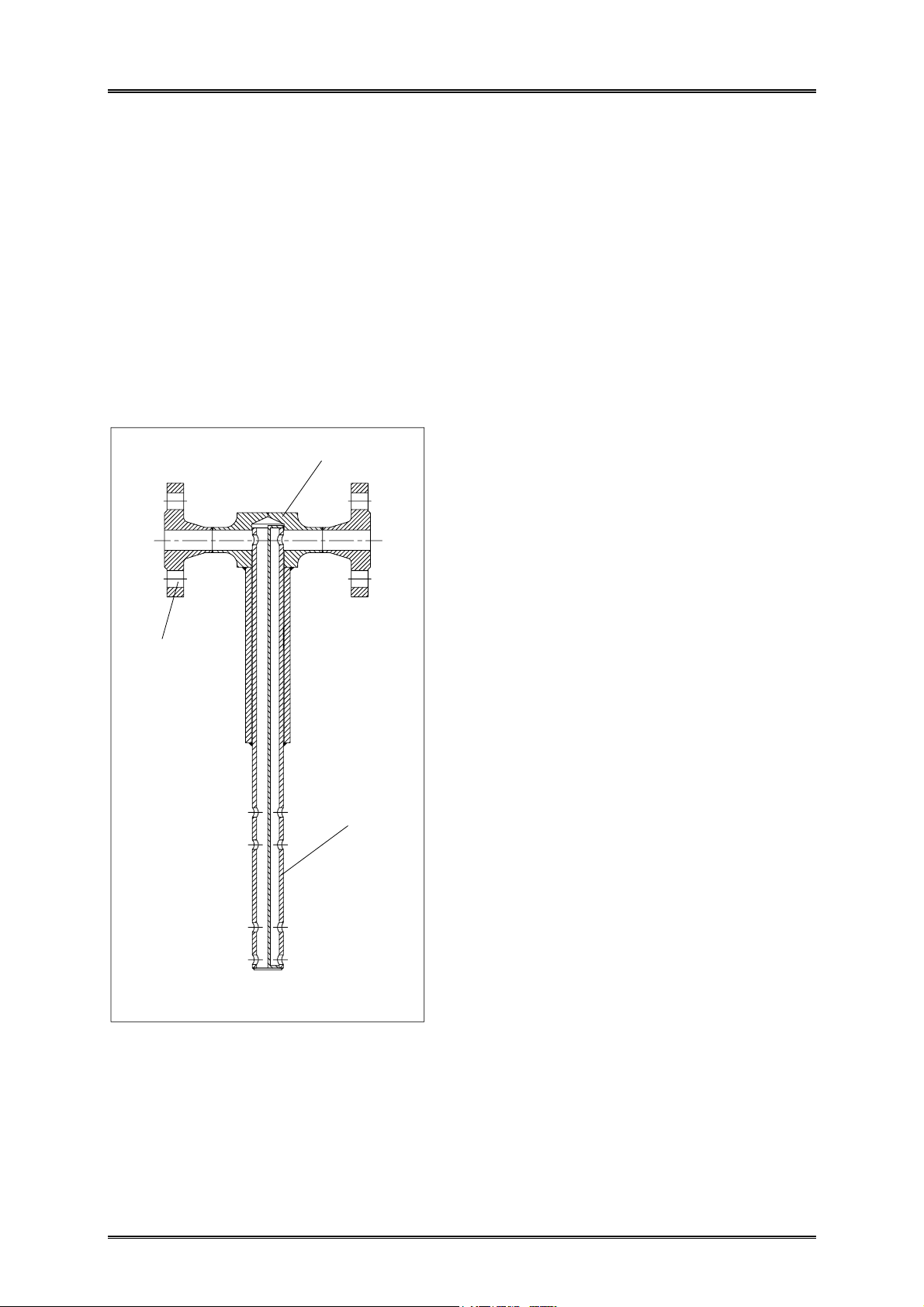
The ITABAR flow sensor is so constructed, that all
cross sections have a min. diameter of 8 mm
(Fig.1). So it´s guarantee, that condensate with a
max drop diameter of 6,5 mm can flow back from
the condensate pots into the flow sensor. So it can
continuous a change of condition of aggregation
from liquid to steam. (Prandl,L. "Führer durch
Strömungslehre).
sensor head
connection
condensate pots
sensor profile
2. General
FTMD Flo-Tap Sensors are designed for
installation under pressure in lines with static
pressure up to 16bar and to 300°C with graphite
packing gland.
All items for installation are provided with FloTaps except for drilling and welding equipment.
These instructions call for the use of a Mueller
DH-5 drilling machine (or equivalent), which is
rated for 80 bar at 35°C with a maximum temperature of 120°C. This machine will handle the
installation under pressure of the Flo-Tap Sensor
FTMD 25 under its full rated pressure of 70 bar.
Other drilling machines are available.
The sensor material and the mounting hardware can
be specially selected to accommodate special
operating conditions (e.g. corrosive media).
3. Pre-Installation Checks
Before installation, make sure that all of the following parts are included in the sensor kit.
• ITABAR Sensor, type FTMD
• condensate pots flanged
• Weld socket
• gaskets for condensate pots flanged
• Sensor end support, with sealing plug
(for FTMD 26 only)
• Instrument valve assembly (if ordered)
Compare the specifications at the type identification plate of the sensor with your order form.
The identification plate contains the following information:
– Serial number
– Type name
– Pipe inside diameter
– TAG number (Measuring location number if furnished)
– Material
Attention!
Make sure that the pipe inside diameter given on
the identification plate matches your pipe diameter.
Fig.1: Cross section ITABAR flow sensor
2
Page 3
ITABAR Flow Sensor Type FTMD Operating manual
4. Equipment required for installation
1. Welding equipment
2. Pressure (hot-tap) drilling machine;
Mueller type DH-5 or equivalent.
3. 1 1/16"drill bit Mueller 33530
4. Drill holder Muelller 33555
5. Adapter nipple Mueller 36195
(Items 2 through 5 are available from Mueller Co.,
Decatur, Illinois. In most cases, the public service
company in your city is available to do the "hottapping" job, or the equipment may be rented or
purchased locally.)
Pressure drill machine and tooling:
Collar
Ratchet handle
Locking mechanism
5. General Installation Notes
In order to obtain optimal measurement results,
follow the notes concerning the installation of the
ITABAR Sensor given below.
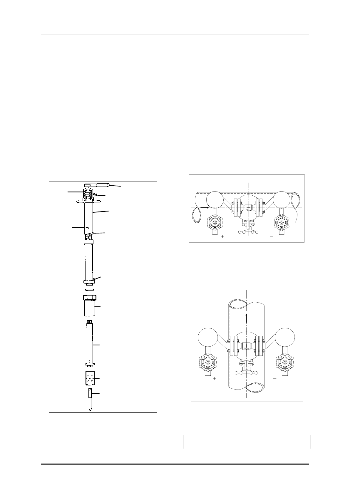
5.1 Determination of Pipe Arrangement
For design reasons, the pipe arrangement at the
installation location has to be known before the
sensor is manufactured.
For horizontal pipe arrangements the instrument
connections are placed in-line with the flow
direction (see Figure 2).
For vertical pipe arrangements, the instrument
connections for the measurement of the differential
pressure are arranged at an angle of 90° to the flow
direction (see Figure 3).
Oil hole
Feed tube and yoke
Clean-out notch
Bleeder valve
Machine adapter nipple
Cutter arbor
Shell cutter
Fig. 2: Placement of the differential pressure
connecting studs for horizontal pipe
arrangement
Pilot drill
Fig. 3: Placement of the differential pressure con-
necting studs for vertical pipe arrangement
The flow direction is indicated in each case by an
arrow on the sensor head.
3
Page 4

ITABAR Flow Sensor Type FTMD Operating manual
5.2 Vertical Pipe Arrangement
5.4 Misalignment
The ITABAR Sensor for flow measurement of
steam and satured steam can be installed in vertical
pipe runs at any location, however, the instrument
connections have to be located in the same
horizontal plain (see Figure 4).
Fig. 4: Installation in vertical pipe
5.3 Horizontal Pipe Arrangement
The ITABAR Sensor operates on the basis of
simple physical principles.
The sensor is not affected by being slightly out of
alignment.
The influence on the accuracy of the measurements
is negligible as long as the limits indicated in
Figures 6, 7 and 8 are not exceeded.
Fig. 6 side view
For flow measurements in a horizontal pipe the
ITABAR Sensor must be installed in the lower half
of the pipe circumference; the connections to the
instruments have to be located below the pipe axis.
Fig. 5: Installation in horizontal pipe
Fig. 7 top view
Fig. 8 front view
4
Page 5

ITABAR Flow Sensor Type FTMD Operating manual
5.5 Required Undisturbed Pipe Run Lengths (in multiples of D)
The accuracy of the measurements of the ITABAR
Sensor depends on the development of a stream
profile which should be as undisturbed as possible.
Therefore the selection of the installation location
within the pipe run is of considerable importance.
The following tried and true hints regarding the
required pipe lengths ahead of and behind the
sensor are designed to help you in your selection of
the most advantageous installation location.
As a general rule, regulating valves, throttle valves
and gate-type valves should be installed behind the
sensor.
Note:
If the recommended straight pipe run lengths are
not available, the measuring accuracy can be
adjusted to the specific conditions of the measuring
stretch by conducting a comparison measurement
(e.g. Pitot tube, point measurement).
The point measurement guarantees that the
differential pressure corresponds to the true flow
velocity, thereby assuring the specified accuracy.
Details can be requested from the manufacturer.
D = Pipe Diameter
A=Upstream B=Downstream
7
9
17
18
3
3
4
4
Restriction in the Pipe Run
Widening of the Pipe Run
Regulation Device
5
7
7
24
3
3
4
Page 6

ITABAR Flow Sensor Type FTMD Operating manual
6. Installation of the ITABAR Sensor
Observe the general installation notes!
6.1 Installation of Type FTM-20 and FTM-25
1. Verify that the line pressure is with rated limits
of the drilling equipment to be used.
2. Grind off paint or other coatings from the pipe
in the area where the Flo-Tap is to be installed.
3. Tack the mounting stud {1} (supplied with the
Flo-Tap) onto the pipe leaving a clearance of 12 mm (Fig. 9).
4. Check the alignment of the mounting stud
again. Then the finish weld can be made.
5. Fasten unit isolating valve {2} to the mounting
stud {1} and open valve. (Fig. 9).
2
1
Fig. 9: Mounting stud with isolating valve
6. Fasten special adapter flanged nipple to unit
isolating valve (Fig. 10).
7. Install cutter arbor, shell cutter and pilot drill to
pressure drilling machine and attach the
machine to its special flanged nipple.
8. Drill through the pipe wall in accordance with
the instructions supplied with the drilling
machine. For type FTMD-25 ∅ 35mm.
9. Withdraw the drill past the Flo-Tap unit
isolating valve. Close the unit valve and remove
drilling machine and special flanged nipple.
Check for leakage at valve and connections.
Fig. 10: Drilling machine with adapter nipple
mounted on unit isolating valve
11. Now seal the threaded stud {5} with a suitable
sealing compound (Fig. 11).
12. Install the threaded stud {5} on the isolating
valve {2} (Fig. 9 and 11).
13. Verify that the instrument valves are fully
closed.
14. Check all connections for leakage by cracking
open the unit isolating valve. If necessary,
screw down the 4 screws {6} of the top packing
gland and the 4 screw nuts {7} of the bottom
packing gland (Fig. 11).
15. Increase line pressure to normal limits and
check for leakage. If there is no apparent
leakage, proceed to Flo-Tap Insertion 6.3.
10. Verify that the sensor profile {4} is fully
retracted in the protection pipe {3}. Check the
position of the threaded rod (Fig. 11)
6
Page 7

ITABAR Flow Sensor Type FTMD Operating manual
Installation of the end support:
4. Take a cord and tie one end around the installed
weld socket {4}. Wrap the other end of the cord
around the pipe so that it forms a loop around
the pipe. Mark the half-way point of the pipe
circumference on the pipe.
8
6
10
7
3
4
5
Fig. 11 Sensor profile with protection pipe
6.2 Installation of Type FTMD-26
The design of the ITABAR Sensor of the type
FTMD-26 is almost identical to the type FTMD-25.
The only difference is the sensor end support (with
sealing plug, see Fig. 12) which permits higher
stream velocities in the pipe.
Attention!
Due to construction of the FTMD-26 with end
support it would cause many problems to install it
for the first time during operation.
We recommend you to install this type during
operation stop as per following instructions.
After installation also this sensor can rejected and
inserted as type FTMD-25 under pressure.
Installation of weld socket:
1. Drill a hole of 35 mm diameter into the pipe.
2. Tack the weld socket {1} onto the pipe leaving
approx. 2 mm clearance. Align the socket (e.g.
with a bolt or pin) so that it is exactly perpendicular to the pipe axis (Fig. 12).
3. Before final welding and installing the sensor,
you have to mount the end support {5}.
5. Now drill a second hole of ∅35 mm diameter
into the pipe.
6. Remove the sealing plug {9} (if present) from
the sensor end support. Tack the sensor end
support onto the pipe leaving approximately 2
mm clearance. (Fig. 12)
7. Insert the sensor into the pipe and check the
alignment of the sensor end support. If
necessary, correct the alignment.
2
1
59
Fig. 12: Installation hardware and sensor end
support
8. Now the final welding can be carried out.
Check the alignment of the weld socket again!
For permissible deviations, see chapter 5.4. .
9. For sensor end supports with sealing plug only:
Seal the thread of the sealing plug {9} with a
suitable sealing compound (e.g. PTFE tape).
Screw the sealing plug into the sensor end
support and tighten it firmly (Fig. 12).
10. Install the Flo-Tap unit isolating valve {2} on
the welding socket. Verify that the valve is in
fully open position, and that the stem is in line
with the pipe to insure clearance for the insertretract rods.
11. Perform the installation of the sensor into the
pipe according to the instructions given in
chapter 6.1 steps 10 through 15.
7
Page 8

ITABAR Flow Sensor Type FTMD Operating manual
6.3 Insertion Procedure for FTMD
1. Verify that the Flo-Tap insert-retract
mechanism are in the position as shown in Fig.
13.
2. Verify that the Flo-Tap instrument valves {8} are
fully closed and that the unit isolating valve {2}
is fully open (Fig. 13 and 14).
3. Initiate probe insertion by rotating the drive
nuts {10} clockwise as viewed from the top,
using ratchet wrench. The nuts must be
tightened alternately, about two turns at time to
prevent binding resulting from unequal loading.
Continue this procedure until probe contacts the
opposite side of the pipe or end support
(FTMD-26)
4. Inspect the packing gland for evidence of
leakage. If the unit was ordered with hightemperature gland, additional adjustment may
be required at this time.
5. Connect instrument lines to the instrument
valves and to the appropriate meter, recorder,
transmitter or controller.
6. Open the Flo-Tap instrument valves {8}. Then
purge or bleed the connecting lines and readout
equipment as required.
6.4 Retract Procedure for FTMD
1. Fully close the Flo-Tap instrument valves {8}.
Then, if required, depressurize and disconnect
the instrument lines.
2. Loosen slightly packing gland {6+7} before
proceeding with retraction.
3. Retract the Flo-Tap by rotating the drive nuts
{10} clockwise as viewed from the top, using
ratched wrench. The nuts must be turned
alternately, about two turns a time, to prevent
binding resulting from unequal loading.
Continue this procedure until the probe is fully
retracted as shown in Fig. 14.
Fig. 13 retracted Flo-Tap Sensor
8
6
10
3
4
8
6
10
3
7
4
1
Fig. 14 retracted Flo-Tap Sensor
2
8
Page 9

ITABAR Flow Sensor Type FTMD Operating manual
4. After the probe is fully retracted, the Flo-Tap
unit isolating valve {2} may closed for
complete disassembly.
7. Insulation
It is important for proper operation of the ITABAR
steam sensor that the phase change from vapour to
liquid take place only in the therefore specially
designed condensation vessels and not in the head
of the sensor.
Attention!
Do not insulate the condensation vessels.
The media in the differential pressure lines and
transmitter must be in a liquid state.
8. Installation of valve block and
∆p-transmitter
8.1. Valve block
For steam measurement a 3-valve instrument
manifold is recommended. The valves of a 3-valves
manifold have the following functions:
• Valve C and D shutt-off to transmitter,
• Valve E Bypass valve (transmitter zero),
If a 5-vlave instrument manifold be used the value
has additiona function:
• value F and G for drains
See Fig. 11
8.2. ∆p-Transmitter:
For steam measurements, the differential pressure
transmitter should always be installed below the
ITABAR sensor in order to avoid the occurrence of
air bubbles in the instrument connections (see Fig.
11). Take care to mount the dp-transmitter exactly
horizontal, otherwise a small difference to
alignment is followed by a zero point error.
We recommend you to install the differential
pressure lines close together (connect hi and lo line
heat conducting) to maintain equal temperature.
Attention!
The differential pressure lines must have a min. inside
diameter from 10mm. Because the max. drop diameter
from water is 6,5mm.
(Prandl, L. "Führer durch Strömungslehre")
Fig. 11
9. Measurement Start-Up
Make sure that:
- all installation openings are closed,
- all installed parts are securely bolted together,
- all shut-off valves are closed,
- close valve A and B for 15 minutes, so that
water can constitute in the condensate pots.
- all valves of 3- or 5-way manifold are closed.
- open valves A and B, after then all valves at the
3-way manifold.
Attention: If a 5-way manifold valve are
mounted
valves F and G must be closed, because after
the
condensate steam penetrate and this can be
daugerous for personal.
- After 5 minutes, water will be constitute from
the lowest point to the condensate pots.
- close valves A and B and open vent valves C
and D, so air bubbles can escape.
- close valves C and D again, the transmitter must
show an 4 mA signal. By using a transmitter
with 0-20 mA output, it must be 0 mA.
- If the output signal from the transmitter is
more then 0 or 4 mA, the condensate pots don`t
have the same level.
- By difference, the transmitter must adjust to 0
or 4 mA.
- close valve E of the 3- or 5-way manifold. After
open valves A and B, the measuring are in
operation.
9
Page 10

ITABAR Flow Sensor Type FTMD Operating manual
- If the mA- signal have big bounce, the valves A
and B must be closed and the system must be
vented again.
10. Preventive Maintenance
ITABAR sensors are intensive to dirt and soil
build-up and therefore nearly maintenance-free.
However, if cleaning is required:
- remove the sensor
- flush completely
- hand clean with a soft wire brush
11. Trouble shooting
If, after start-up of the ITABAR sensor, any
measuring errors accur, they may possibly be
corrected quite easily:
Error:
No differential pressure indication.
Correction:
Check whether all instrument valves to the
∆p-transmitter are opened.
The valve E must be closed (only for zero).
Check the alignment of the sensor with the pipe.
The arrow on the sensor must point exactly in the
flow direction (downstream).
Note:
Two-Phase flow or alternating phase flow will
cause an erratic spiking signal. The ITABAR
sensors are head-measuring devices and will not
accurately measure two-phase flow.
ITABAR-Flow-Sensors for low pressure steam
have condensate pots in which the condensate
water line is 25mm higher than the flange
connection of the sensor is installed precise
horizontal.
That means that water column of static and
dynamic pressure side must have the same high to
guarantee zero differential pressure when steam is
not flowing.
The arrangment of higher condensate line than
sensor connection has been done to secure the exact
water column onto the d.p. transmitter.
During steam flow the steam will move into the
condensate pots and will condensate to water. The
water level above line 1 will flow back into the
sensor and change again into steam. The steam
pressure from dynamic and static connection is
pressing onto the water level and the difference at
these pressures will be transmitted into mA-signal
through the differential pressure transmitter.
Please note that 25mm deviation in the line of 1
will give 25mm WG differential pressure.
10
 Loading...