

Page 1
ITABAR-Sensor Type IBFD Operating Manual
Type IBFD
Contents:
0. Principle of flow measuring with ITABAR-Flow-Sensor............................................2
1. Product Description ......................................................................................................... 2
2. Operating Conditions.......................................................................................................2
3. Pre-Installation Checks....................................................................................................2
4. General Installation Notes ...............................................................................................3
5. Installation of the ITABAR Sensor .................................................................................7
6. Insulation .......................................................................................................................11
8. Measurement Start-Up...................................................................................................13
9. Preventive Maintenance.................................................................................................13
10. Trouble shooting sensors with condensate pots.............................................................13
INTRA-AUTOMATION GmbH
Meß- und Regelinstrumente
Otto-Hahn-Straße 20
41515 Grevenbroich
Tel.: 0 21 81 / 7 56 65 - 0
Fax: 0 21 81 / 6 44 92
Internet: www.intra-automation.de
E-Mail:
info@intra-automation.de Dok.: BA_IBFD_en_041201.DOC
1
Page 2

ITABAR-Sensor Type IBFD Operating Manual
0. Principle of flow measuring with
ITABAR-Flow-Sensor
If there will be insert a sensor rounded on the face in
a parallel stream with velocity w, damming up of the
fluid will be the result. In the middle of this area are
streamlines, called damming up streamlines, which
will be vertical to the sensor. Velocity of the
becomes approximately zero at this significant point.
Everytime damming up streamlines are laminar. In
this case flow measurement can be handle very easy
(no friction):
Using the theme of Bernoulli, you can calculate:
p
ges
= p
+ ½ w².
stat
With the patented profil of the ITABAR-FlowSensor you can measure the total pressure p
upstreams and the and the static pressure p
ges
stat
downstreams. The difference between static and
total pressure is:
w = (2/ρ p
dyn
)½.
By knowing the innerside pipe diameter it applies to
the theme of continuity:
V ∼ w A.
Using a proportional factor, called correction factor
k, you can calculate in accordance with the
following formula:
V = k w A or m = k ρ w A.
This correction factor k is a value only depending on
the ITABAR-Flow-Sensor-Profil. This value had
been find out by INTRA-AUTOMATION
empirically.
Specially for steam-measuring you can not measure
the differencial pressure with electrical or pneumatic
transmitter directly (max. temperature of medium <
100°C). You have to use impulse pipes containing
an identical head of condensate at identical
temperature. To get this result ITABAR-Sensors
will be delivered everytime with condensate
reservoirs. The flow of steam will not demage the
transmitter. But you can only calculate in
accordance with the theme of pressure transmission
(Pascal), if there will be no air in the pressure pipe
and the chambers of the transmitter. If there is air in
it, you can not neglect friction. The dynamic energy
will not be transmitted to the differential transmitter
without faults. You will not get correct measuring
results.
1. Product Description
We congratulate you on your purchase of an
ITABAR Flow Sensor type IBFD.
When installed properly, the ITABAR sensor offers
an array of advantages over other measurement
systems with respect to its accuracy, pressure loss,
and installation. The following guide line is
designed to help you with the sensor installation and
operation.
ITABAR-Flow-Sensors are designed in the way that
the innerside profil diameter will not be smaller than
8 mm. This guarantees condensate drops with a
maximal diameter of 6.5 mm will not prevent a
correct measuring (Prandtl, L.).
2. Operating Conditions
ITABAR Flow sensors type IBFD can be used under
the following conditions:
• Operating pressure: max. 400 bar at 300 °C
max. 160 bar at 590 °C
• Nominal Pipe
Diameters: DN 40 to DN 1000
3. Pre-Installation Checks
Before installation, make sure that all of the
following parts are included in the sensor kit:
• ITABAR-Sensor, Type IBFD
• condensation vessels, flanged or direct welded
on sensor head
• Mounting flange with weld stud
• Gasket for the mounting flange and flanged
model of condensation vessels
• Bolts and nuts (material suitable for temperature
and pressure rating)
• Sensor end support with sealing plug up to
PN 40, for higher pressure closed type
• Instrument valve assembly (if ordered)
NOTE:
The ITABAR type IBFD-26/36 HTG is a
completely welded construction, there are no
flanges, gaskets, stud bolts or nuts needed.
Compare the specifications on the type identification
plate on the sensor with your order form.
The identification plate contains the following information:
• Serial number
• Type name
• Pipe inside diameter
• TAG number
(Measuring location number - if furnished)
• Material
ATTENTION!
You must make sure that the pipe inside diameter
given on the identification plate matches your pipe
diameter.
2
Page 3

ITABAR-Sensor Type IBFD Operating Manual
4. General Installation Notes
In order to obtain optimal measurement results,
follow the notes concerning the installation of the
ITABAR sensor given below.
4.1. Determination of Pipe Arrangement
For design reasons, the pipe arrangement at the
installation location has to be known before the sensor is manufactured. Since the ITABAR sensors for
vertical lines are not interchangeable with those for
horizontal lines.
• Pipe arrangement, horizontal or vertical
• flow direction (only for models with direct
welded condensation vessels)
• Wall thickness of pipe
For horizontal and vertical pipe run the
condensation vessels have to be arranged in the
same horizontal plain.
Compare Fig. 3b and 4b.
Differential pressure tap
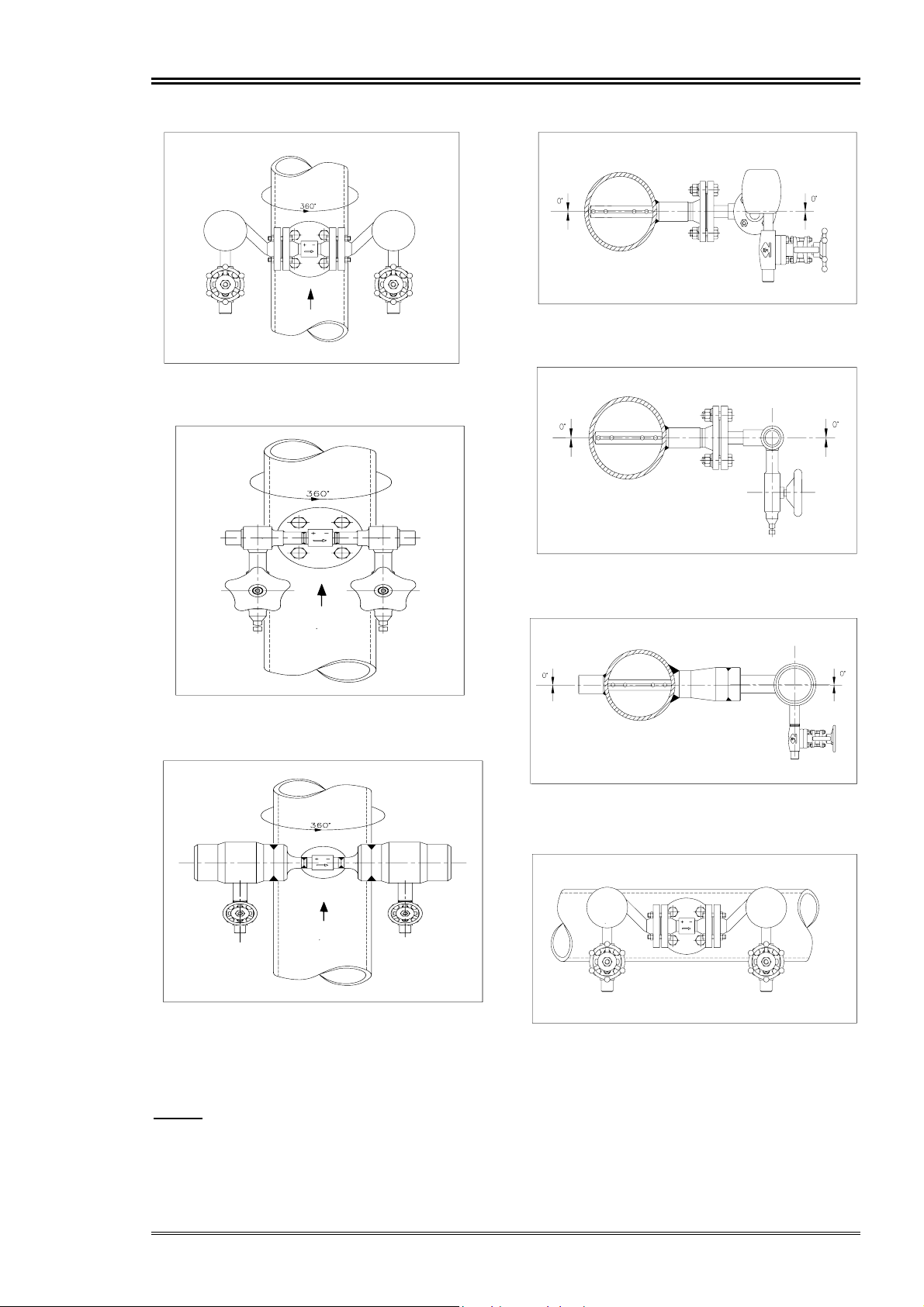
4.2. Vertical Pipe Arrangement
The ITABAR sensor for flow measurement of steam
and saturated steam can be installed in vertical pipe
runs at any location, however, the instrument
connections have to be located in the same
horizontal plain (Fig. 3a and 3b).
Fig. 3a: Installation for vertical pipe run,
example type IBFD-25…K1H-A81
Fig. 1: Horizontal pipe run
Fig. 2: Vertical pipe run
The flow direction is indicated in each case by the
arrow on the sensor head.
Fig. 3a: Installation for vertical pipe run,
example type IBFD-25….-K5-A16
Fig. 3a: Installation for vertical pipe run,
example type IBFD-26 HTG… -K5-A16
3
Page 4
ITABAR-Sensor Type IBFD Operating Manual
Fig. 3b: Installation for vertical pipe run
example type IBFD-25…-K1H-A81
Fig. 3b: Installation for vertical pipe run
example type IBFD-25…-K7-A18
Fig. 4a: Installation for horizontal pipe run,
example type IBFD-25…-K1H-A81
Fig. 4a: Installation for horizontal pipe run,
example type IBFD-25….-K5-A16
Fig. 3b: Installation for vertical pipe run
example type IBFD-25 HTG….K5-A16
4.3. Horizontal Pipe Arrangement
Always install the ITABAR steam sensor
horizontally with the instrument connections
(condensation vessels) along a horizontal line.
(Fig. 4a and 4b).
Fig. 4a: Installation for horizontal pipe run,
example type IBFD-26-HTG…K5-A16
Fig. 4b: Installation for horizontal pipe run,
example type IBFD-25….-K1H-A81
4
Page 5

ITABAR-Sensor Type IBFD Operating Manual
The tolerances given in the following figures valid
both vertical and horizontal steam lines.
5°
Fig. 4b: Installation for horizontal pipe run,
example type IBFD-25…-K7-A18
Fig. 4a: Installation for horizontal pipe run,
example type IBFD-26-HTG…-K5-A16
3°
Fig. 6: Horizontal pipe run (top view),
example type IBFD-25 without
condensation vessel
1°
Fig. 5: Horizontal pipe run,
example type IBFD-25…-K7-A18
4.4. Misalignment
The ITABAR sensor operates on the basis of simple
physical principles.
Its design incorporates no moving parts which are
subject to wear.
The sensor is not affected by being slightly out of
alignment.
The influence on the accuracy of the measurements
is negligible as long as the limits indicated in
Figures 5, 6 and 7 are not exceeded.
Take care to prevent unequal heights of condensate
in the vessels. The max. deviation from the
horizontal line is 1° (see Fig. 7).
Fig. 7: Horizontal pipe run,
example type IBFD-25…-K7-A18
5
Page 6

ITABAR-Sensor Type IBFD Operating Manual
4.5. Required Undisturbed Pipe Run Lengths
(in multiples of D)
The accuracy of the measurements of the ITABAR
sensor depends on the development of a stream
profile which should be as undisturbed as possible.
Therefore the selection of the installation location
within the pipe run is of considerable importance.
The following tried and true hints regarding the
required pipe lengths ahead of and behind the sensor
are designed to help you in your selection of the
most advantageous installation location.
As a general rule, regulating valves, throttle valves,
and gate-type valves should be installed behind the
sensor.
D=Pipe Diameter
NOTE:
If the recommended straight pipe run lengths are not
available, the measuring accuracy can be adjusted to
the specific conditions of the measuring stretch by
conducting a comparison measurement.
The measurement guarantees that the differential
pressure corresponds to the true flow velocity,
thereby assuring the specified accuracy.
Details can be requested from the manufacturer.
A=Upstream B=Downstream
7
3
Restriction in the Pipe Run
Widening of the pipe Run
Regulating Device
9
17
18
7
7
3
4
4
3
3
24
6
4
Page 7

ITABAR-Sensor Type IBFD Operating Manual
5. Installation of the ITABAR Sensor
In difference to other suppliers the ITABAR-FlowSensor everytime will be build in in the horizontal
line of the pipe and always have condensate pots.
Therefore the influence of condensation and
vaporization is minimized. Please pay attention that
both condensate levels on plus and minus pressure
pipe will be the same. This means both pots must be
on the same horizontal line and there has to be no air
in the pulse tubes and the chambers of the
transmitter.
Following problems will happened by using sensors
of other manufactors who does not use condensate
pots or prefered installation of the sensor on the
lower side of the pipe:
• Condensation and vaporization happened in the
sensor profil. For this reason there is a great
influence to the level of the condensate column.
• There is no energy balance between plus and
minus process connection.
• no equal temperatures in the condensate
columns.
• No chance to correct misalignments
It is not allowed to install ITABAR-Flow-Sensor at
the top of the pipe. If costumer did so, he is not able
to get out all air from the sensor and the condensate
pots. The energy of the system will not be
transmitted without loss to the transmitter. The
kinetic energy will be changed particulary changed
to potential energy. This is eliminated for ITABARFlow-Sensors.
Observe the general installation instructions!
It is particularly important to make sure that the
distance from the gasket surface to the pipe agrees
with the H-dimension you gave in your order (see
Fig. 8).
ITABAR sensors of the type IBFD are supplied with
the following standard H-dimensions:
IBFD-20/21 80 mm
IBFD-25/26 127 mm
IBFD-35/36 150 mm
IBFD-26/36 HT 200 mm
IBFD-26/36 HTG 168 mm
5.1. Installation of Type IBFD-20
H
Fig. 8
3. Observe the H-dimension during the welding of
the mounting flange (see also Fig. 8).
4. Check the alignment of the mounting flange
again - this is importatnt for the exact position of
the condensation vessels.
5. Now the ITABAR sensor can be installed into
the pipe. Place the included gasket on the gasket
surface of the flange. Insert the sensor into the
welded stud and make sure that the arrow on the
sensor flange points in the flow direction.
Tighten the bolts and nuts.
6. Now check the alignment of the condensation
vessel. The condensation vessel have to be
perfectly mounted along a horizontal line.
Check the alignment!
For correction of alignment slightly release stud
bolts on the mounting flange. For correct alignment tighten stud bolts with required torque
according table 1.
H
45°
1. Drill a hole of 18 mm diameter into the pipe.
2. Tack the mounting flange onto the pipe leaving a
clearance of 1-2 mm. The bolt holes of the flange
must be at 45° angles to the pipe axis (see Fig.
9).
Check the alignment of the mounting flange.
Fig. 9
7
Page 8

ITABAR-Sensor Type IBFD Operating Manual
Thread Torque max. Temp.
M12 2,5 - 3 Mkp 300°C
M12 3,5 - 4 Mkp >300°C
M16 5,5 - 6 Mkp 300°C
M16 9 - 9,5 Mkp >300°C
M20 11,5 - 12 Mkp 300°C
M20 18 - 18,5 Mkp >300°C
M24 19 - 19,5 Mkp 300°C
M24 30 - 31,5 Mkp >300°C
Table 1
5.2. Installation of Type IBFD-21
The design of the ITABAR sensor IBFD-21 is
almost identical to the type IBFD-20. The only
difference is the end support for type IBFD-21 (see
Fig. 10), which permits higher stream velocities in
the pipe.
Except for the installation of the sensor end support,
the installation steps are identical to those for type
IBFD-20.
Installation of the closed sensor end support:
1. Install the mounting flange as already described
under chapter 5.1. points 1 to 3.
6. Remove the sensor.
7. Finish welding of mounting flange and end
support can be made.
8. Perform the installation of the sensor into the
pipe according to the instructions given in
chapter 5.1. points 5 and 6.
5.3. Installation of type IBFD-25/35
The installation of the types IBFD-25/35 correspond
to the type IBFD-20.
ATTENTION!
For the installation are following hole-diameters for
mounting stud/flange and end support requested:
IBFD-25 35 mm
IBFD-35 45 mm
IBFD-36-HTG 47 mm mounting stud
41 mm end support
NOTE:
On flanges with eight bolt holes, the welding stud
must be welded on so that the bolt holes in the
flange form an angle of 22.5° with the pipe axis (see
Fig. 11).
2. Take a cord and tie one end around the existing
weld stud. Wrap the other end of the cord around
the pipe so that it forms a loop around the pipe.
Mark the half-way point of the pipe
circumference on the pipe.
3. Now drill a second hole of 18 mm diameter into
the pipe.
4. Insert the ITABAR sensor through the mounting
flange and check correct alignment.
Put the end support on the tip of the sensor.
Fig. 10
5 Tack the sensor end support with 2 mm
clearance onto the pipe.
22,5°
Fig. 11
5.4. Installation of type IBFD-26/36 and IBFD26/36 HTG
The installation of these ITABAR sensors correspond to the installation of type IBFD-21.
Please look at chapter 5.2.
Note that the a.m. sensor types will delivered
normally with a closed sensor end support.
The plugged sensor end support is only up to
pressures of 40 bar available.
ATTENTION!
For the installation are following hole-diameters for
mounting stud/flange and end support requested:
IBFD-26 35 mm
IBFD-26 HTG 35 mm
IBFD-36 45 mm
IBFD-36 HTG 47mm
Installation of the closed end support:
8
Page 9

ITABAR-Sensor Type IBFD Operating Manual
Please refer to chapter 5.2 for installation of closed
sensor end support.
Take care of the diameters of the hole!
Installation of sensor end support with sealing plug:
1. Install the mounting flange as already described
at chapter 5.1. points 1 to 3.
2. Take a cord and tie one end around the existing
weld stud. Wrap the other end of the cord around
the pipe so that it forms a loop around the pipe.
Mark the half-way point of the pipe
circumference on the pipe.
3. Now drill a second hole of 35 mm (IBFD-26)
respectively 45 mm diameter (IBFD-36) into the
pipe.
4. Insert the ITABAR sensor through the mounting
flange and verify the alignment.
Push the end support over the sensor tip of the
opposite side of the pipe.
5 Tack the sensor end support onto the pipe
leaving approximately 2 mm clearance.
6. Remove the sensor from the pipe.
7. Finish welding of mounting flange and end
support can be made.
8. Seal the thread of the sealing plug with a suitable
sealing compound (e.g. PTFE tape). Screw the
plug into the sensor end support and tighten it
firmly.
9. Perform the installation of the sensor into the
pipe according to the instructions given in
chapter 5.1. points 5 and 6.
5.5. Installation of type IBFD-26/36 HTG
The sensor type IBFD-26/36 HTG is a special fully
welded construction for high pressures and
temperatures. Mounting stud and sensor will welded
each another to prevent any leakage.
To remove the sensor if required you have only to
separate mounting stud and sensor by cutting the
weld between this two parts (see Fig. 12).
ATTENTION!
Please take care on the H-dimension in case you did
not co-ordinate the weld preparation of the pipe
system with our work.
To make sure that sensor matches your preparation
consult now our engineers.
Installation of type IBFD-26/36 HTG:
1. Drill a hole of 30 mm (IBFD-26 HTG)
respectively 47 mm diameter (IBFD-36 HTG)
into the pipe.
2. Tack the mounting stud onto the pipe leaving a
clearance of 4 mm. Check the alignment of the
stud.
The stud have to be mounted exact rectangular to
the pipe axis. Verify the correct alignment. Then
the finish weld can be made.
3. Take a cord and tie one end around the existing
weld stud. Wrap the other end of the cord around
the pipe so that it forms a loop around the pipe.
Mark the half-way point of the pipe
circumference on the pipe.
4. Now drill a second hole of 35 mm (IBFD-26
HTG) respectively 41 mm diameter (IBFD-36
HTG) into the pipe.
5. Insert the sensor into the mounting stud. Align
the sensor exactly along a horizontal line. Tack
the sensor with 4 mm clearance to the mounting
stud. Check H-dimension again.
6. Put the end support on the tip of the sensor. Tack
the end support with 4 mm clearance onto the
pipe. Correct the alignment.
7. Now the finish weld between sensor and
mounting stud can be carried out.
8. At least the end support can be finish welded.
Disassembly:
If required the weld between mounting stud and
sensor can be separated for disassembly. While the
tolerance between sensor end endsupport is 0.2 mm,
it can happened that the sensor will be welded
together with the endsupport in inappropriate way.
Then the endsupport has to be seperated also.
Mounting
weld seam
Fig. 12: Disassembly of type IBFD-26/36 HTG
5.6. Installation of Type IBFD-65
9
Page 10

ITABAR-Sensor Type IBFD Operating Manual
The installation of the types IBFD-65 correspond to
the type IBFD-20. The only different is, that the
mounting stud is designed with a weldolet.
1. Drill a hole of 60 mm diameter into the pipe.
2. Tack the mounting flange onto the pipe leaving a
clearance of 4 mm. The bolt holes of the flange
must be at 22,5° angles to the pipe axis (see Fig.
13). Check the alignment of the mounting
flange.
22,5°
Fig. 13
3. Observe the H-dimension during the welding of
the mounting flange (see also Fig. 14).
ment tighten stud bolts with required torque
according table 1.
5.7. Installation of Type IBFD-66
The design of the ITABAR sensor IBFD-66 is
Fig. 14
4. Check the alignment of the mounting flange
again - this is important for the exact position of
the condensation vessels.
5. Now the ITABAR sensor can be installed into
the pipe. Place the included gasket on the gasket
surface of the flange. Insert the sensor into the
welded stud and make sure that the arrow on the
sensor flange points in the flow direction.
Tighten the bolts and nuts.
6. Now check the alignment of the condensation
vessel. The condensation vessel have to be
perfectly mounted along a horizontal line.
Check the alignment!
For correction of alignment slightly release stud
bolts on the mounting flange. For correct align-
10
Page 11

ITABAR-Sensor Type IBFD Operating Manual
almost identical to the type IBFD-65. The only
difference is the end support (with a weldolet for
type IBFD-66 ; see Fig. 15), which permits higher
stream velocities in the pipe.
Except for the installation of the sensor end support,
the installation steps are identical to those for type
IBFD-65.
Installation of the closed sensor end support:
1. Install the mounting flange as already described
under chapter 5.6. points 1 to 6.
2. Take a cord and tie one end around the existing
weld stud. Wrap the other end of the cord around
the pipe so that it forms a loop around the pipe.
Mark the half-way point of the pipe
circumference on the pipe.
3. Now drill a second hole of 60 mm diameter into
the pipe.
4. Insert the ITABAR sensor through the mounting
flange and check correct alignment. Put the
weldolet (item A, fig. 15) on the pipe.
Fig. 15
5. Tack the weldolet (item A) with 4mm clearance
onto the pipe.
6. Remove the sensor.
7. Finish welding of weldolet (item A).
8. Insert the ITABAR sensor through the mounting
flange and install the ring (item B, fig. 15). If it´s
not possible, because the tolerance of welding
are to much, so you are able to machine the ring
(clearence into the weldolet -0,2mm).
9. Now you can weld the endcap (item C, fig. 15)
onto the weldolet (item A).
6. Insulation
It is important for proper operation of the ITABAR
steam sensor that the phase change from vapour to
liquid take place only in the therefore specially
designed condensation vessels and not in the head
of the sensor.
Therefore, the entire sensor head and all other parts
up to the condensation vessels must be insulated
with a suitable material.
Before being insulated, all piping connections
should be checked for leaks and the instrument
connection for the differential pressure have to be
marked ( + and - ) to prevent confusion.
Finally, the ITABAR TAG-plate must hang outside
the insulation for later identification of the flow
station.
ATTENTION!
Do not insulate the condensation vessels, valves and
the lines to the differential pressure transmitter!
The media there have to be in liquid state.
7. Installation of valve block and
the p-transmitter
7.1. Valve block
For steam measurement a 3-valve instrument
manifold is recommended. The valves of a 3-valve
manifold has the following functions:
• Valve C and D shut-off to transmitter,
• Valve E Bypass valve (transmitter zero),
If a 5-valve instrument manifold will be used the
valve has additional function:
• valve F and G for drains
See Fig. 13a and b
7.2. ∆p-Transmitter
For steam measurements, the differential pressure
transmitter should always be installed below the
ITABAR sensor in order to avoid the occurrence of
air bubbles in the instrument connections (see
Fig. 13a and b). Take care to mount the dptransmitter exactly horizontal, otherwise a small
difference to alignment is followed by a zero point
error.
We recommend you to install the differential
pressure lines close together (connect hi and lo line
heat conducting) to maintain equal temperature.
11
Page 12
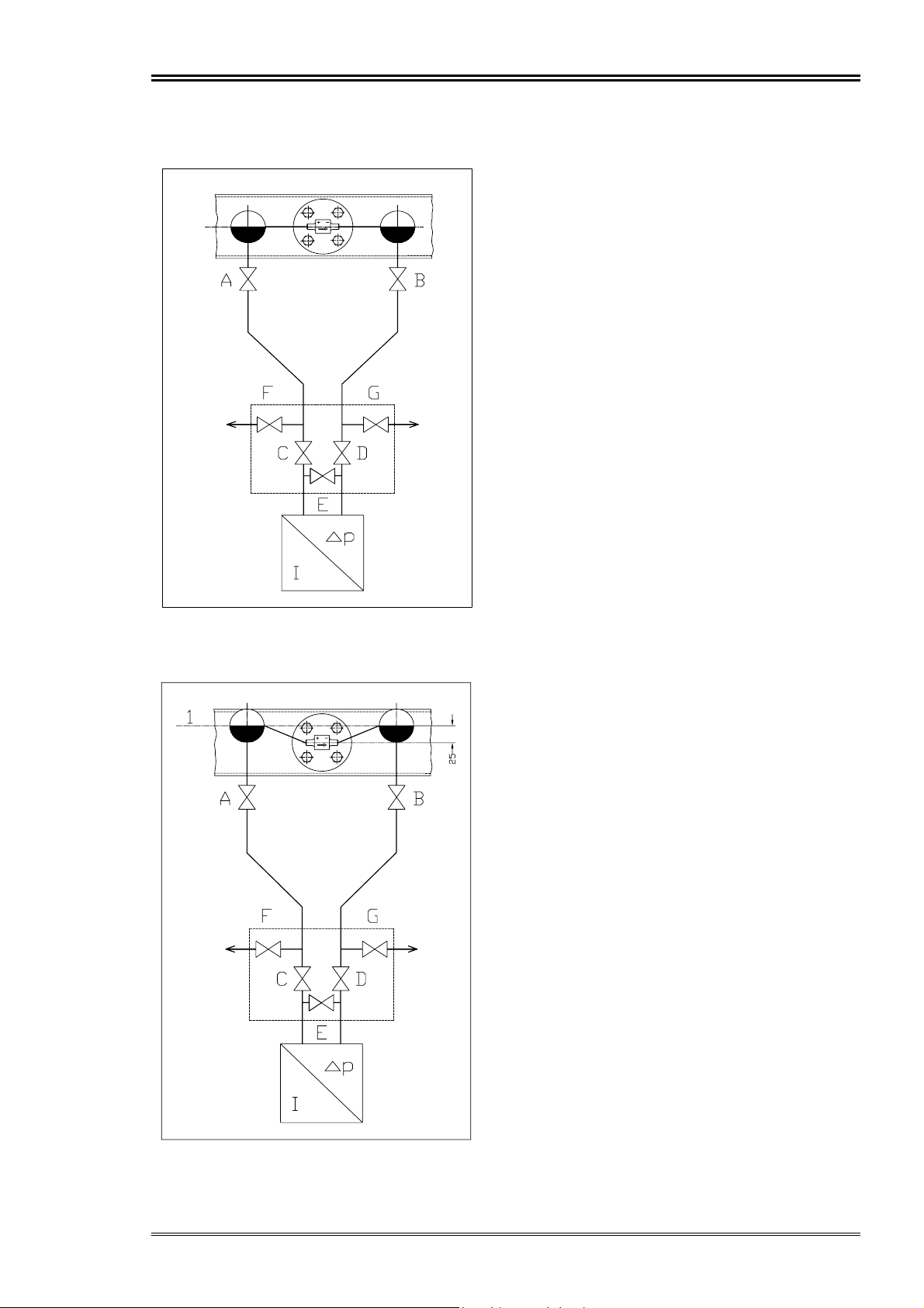
ITABAR-Sensor Type IBFD Operating Manual
Sensor with condensate pots K5/6/7
Fig. 13a
Sensor with condensate pots K1..
Fig. 13b
12
Page 13

ITABAR-Sensor Type IBFD Operating Manual
8. Measurement Start-Up
Make sure that:
- all installation openings are closed,
- all installed parts are securely bolted together,
- all shut-off valve are closed,
- all valves of the 3-valve or 5-valve manifold are
closed
Now the pipe can be cleared for the appropriate
medium.
Check all connections, especially the flange gasket.
It takes about 30-60 minutes that the condensation
vessels will filled with condensate.
Now you can open the primary line valves A and B.
To vent the measuring system open valves F and G.
Close the valves when water without air pockets is
to be seen.
ATTENTION!
Take care that for high pressure application the
vent/drain lines are mounted according to the safety
instructions.
Open now the valves for the
∆p-transmitter (valve C
and D).
Open the valve E for transmitter zero only.
If transmitter zero is O.K. close the valve E. Allow
condensate level to stabilise 1/2 hour before
recording transmitter readings again.
9. Preventive Maintenance
NOTE:
Two-Phase flow or alternating phase flow will cau se
an erratic spiking signal. The ITABAR sensors are
head-measuring devices and will not accurately
measure two-phase flow.
ITABAR-Flow-Sensors for low pressure steam have
condensate pots in which the condensate water line
is 25mm higher than the flange connection of the
sensor is installed precise horizontal.
That means that water column of static and dynamic
pressure side must have the same high to guarantee
zero differential pressure when steam is not flowing.
The arrangment of higher condensate line than
sensor connection has been done to secure the exact
water column onto the d.p. transmitter.
During steam flow the steam will move into the
condensate pots and will condensate to water. The
water level above line 1 will flow back into the
sensor and change again into steam. The steam
pressure from dynamic and static connection is
pressing onto the water level and the difference ot
these pressures will be transmitted into mA- signal
through the differential pressure transmitter.
Please note that 25mm deviation in the line of 1 will
give 25mm WG differential pressure.
ITABAR sensors are insensitive to dirt and soil
build-up and therefore nearly maintenance-free.
However, if cleaning is required:
- remove the sensor
- flush completely
- hand clean with a soft wire brush
10. Trouble shooting sensors with
condensate pots
If, after the start-up of the ITABAR sensor, any
measuring errors occur, they may possibly be
corrected quite easily:
Error:
No differential pressure indication
Correction:
Check whether all instrument valves to the
transmitter are opened.
The valve E must be closed (only for zero).
Check the alignment of the sensor with the pipe. The
arrow on the sensor must point exactly in the flow
direction (downstream).
Error:
Alternating differential pressure
Correction:
Verify that the whole sensor up to the condensation
vessel is insulated.
Remove any insulation from condensation vessels!
∆p
13
 Loading...