

INTORQ BFK470 Series, BFK470-10, BFK470-12, BFK470-14, BFK470-06 Translation Of The Original Operating Instructions
...Page 1

setting the standard
INTORQ BFK470
Spring-applied brake with electromagnetic release
Translation of the Original Operating Instructions
www.intorq.com
www.intorq.com
Page 2

This documentation applies to the:
AABCD
A
A
BCD
Product key
Legend for the product key
INTORQ BFK470
Product group Brake
Product type Spring-applied brake
INTORQ B FK -
Type 470
Size 06, 08, 10, 12, 14, 16, 18
Not coded: Supply voltage, hub bore hole, options
INTORQ | BA 14.0199 | 08/2016 2
Page 3

Identification
Packaging label Example
Manufacturer Bar code
Type (see product key) Type No.
Designation Qty. per box
Rated voltage Rated power Rated torque Hub diameter Packaging date
Note CE mark
Name plate Example
Manufacturer CE mark
Type (see product key)
Designation
Rated voltage Rated power Hub diameter
Type No. Rated torque
Date of manufacture
Document history
Material number Version Description
33001439 1.0 01/2012 TD09 First edition
33001439 1.1 03/2012 TD09 Supplemented the technical data
33001439 1.2 10/2012 TD09 Added to the "Brake assembly" chapter
Updated the "Abbreviations used" table
Supplemented the characteristics, rated data and operating times
33001439 2.0 05/2013 TD09 Degree of protection changed
Added note about the end shield characteristics
Shaft characteristic defined, "Mechanical installation" chapter
"Checking the brake" chapter (maintenance and repair) supple-
mented
33001439 3.0 05/2013 TD 09 Text with regard to the disengagement time updated
33001439 3.1 03/2014 SC
Restructured FM; note concerning brake seal 23
33001439 4.0 01/2015 SC Harmonized connection diagrams
33001439 5.0 08/2016 SC Additional sizes: 06, 08, 10, 12
Refer to www.intorq.de for the latest version of these operating instructions.
INTORQ | BA 14.0199 | 08/2016 3
Page 4

Contents
1 Preface and general information ...........................................................................................................................5
1.1 About these Operating Instructions ...............................................................................................................5
1.2 Terminology used ...................................................................... ....................................................................5
1.3 Conventions in use ........................................................................................................................................5
1.4 Abbreviations used ........................................................................................................................................6
1.5 Safety instructions and notices .....................................................................................................................7
1.6 Scope of delivery ...........................................................................................................................................8
1.7 Disposal ........................................................................................................................................................8
1.8 Drive systems ................................................................................................................................................9
1.9 Legal regulations ...........................................................................................................................................9
2 Safety instructions ...............................................................................................................................................10
2.1 General safety instructions ..........................................................................................................................10
2.2 Application as directed ................................................................................................................................11
3 Technical specifications ......................................................................................................................................12
3.1 Product description .....................................................................................................................................12
3.2 Rated data ...................................................................................................................................................14
3.3 Rated data (dimensioning data) electrical data ...........................................................................................16
3.4 Switching energy / operating frequency ......................................................................................................18
3.5 Emissions ....................................................................................................................................................19
4 Mechanical installation ........................................................................................................................................20
4.1 Important notes ...........................................................................................................................................20
4.2 Assembly .....................................................................................................................................................22
5 Electrical installation ............................................................................................................................................25
5.1 Important notes ...........................................................................................................................................25
5.2 Electrical connection ............. .... .... .... ..........................................................................................................25
5.3 Technical data for inductive proximity sensors ...........................................................................................30
5.4 Minimum bend radius for the brake connection line ....................................................................................31
5.5 Bridge/half-wave rectifier (optional) .............................................................................................................31
6 Commissioning and operation ............................................................................................................................34
6.1 Important notes ...........................................................................................................................................34
6.2 Function checks before commissioning ......................................................................................................35
6.3 Brake with proximity sensor ........................................................................................................................36
6.4 Commissioning ............................................................................................................................................37
6.5 During operation ..........................................................................................................................................37
7 Maintenance and repair ......................................................................................................................................38
7.1 Wear of spring-applied brakes ....................................................................................................................38
7.2 Inspections ..................................................................................................................................................39
7.3 Maintenance ................................................................................................................................................40
7.4 Spare-parts list ............................................................................................................................................43
7.5 Electrical accessories .................................................................... .... .... .... ..................................................43
8 Troubleshooting and fault elimination ...............................................................................................................44
INTORQ | BA 14.0199 | 08/2016 4
Page 5
Preface and general information
1 Preface and general information
1.1 About these Operating Instructions
❚ These Operating Instructions will help you to work safely with the spring-applied brake with electromag-
netic release. They contain safety instructions that must be followed.
❚ All persons working on or with electromagnetically released spring-applied brakes must have the Oper-
ating Instructions available and observe the information and notes relevant for them.
❚ The Operating Instructions must always be in a complete and perfectly readable condition.
1.2 Terminology used
Term In the following text used for
Spring-applied brake Spring-applied brake with electromagnetic release
Drive system Drive systems with spring-applied brakes and other drive compo-
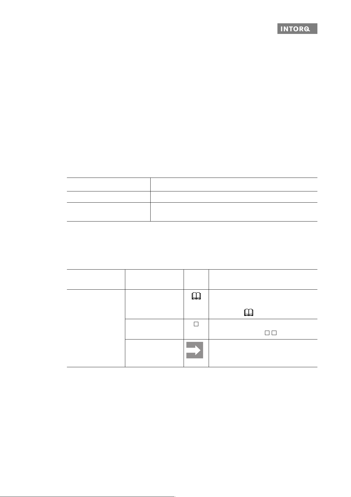
1.3 Conventions in use
This document uses the following styles to distinguish between different types of information:
Spelling of numbers
Symbols
nents
Decimal separator Point The decimal point is always used.
For example: 1234.56
Page reference Reference to another page with additional
information
For example: 16 = refer to page 16
Wildcard Wildcard for options, selections
For example: BFK458- = BFK458-10
Note
Important notice about ensuring smooth
operations or other key information.
INTORQ | BA 14.0199 | 08/2016 5
Page 6

Preface and general information
1.4 Abbreviations used
Letter symbol Unit Designation
F
R
N Rated frictional force
I A Current
I
H
I
L
I
N
M
A
M
dyn
M
K
A Holding current, at 20 °C and holding voltage
A Release current, at 20 °C and release voltage
A Rated current, at 20 °C and rated voltage
Nm Tightening torque of fixing screws
Nm Braking torque at a constant speed of rotation
Nm Rated torque of the brake, rated value at a relative speed of rotati on of
100 rpm
n
max
P
H
P
L
P
N
rpm Maximum occurring speed of rotation during the slipping time t
W Coil power during holding, after voltage change-over and 20 °C
W Coil power during release, before voltage change-over and 20 °C
W Rated coil power, at rated voltage and 20 °C
Q J Quantity of heat/energy
Q
E
J Max. permissible friction energy for one-time switching, thermal parameter of
the brake
3
Q
Q
R
S
S
S
s
s
s
s
t
t
N
h
hue
hmax
L
LN
Lmin
Lmax
1
2
R
Smax
J Braking energy, friction energy
J Maximally permissible friction energy for cyclic switching, depending on the
operating frequency
Ohms Rated coil resistance at 20 °C
1/h Switching frequency: the number of switching operations evenly spread over
the time unit
1/h Transition operating frequency, thermal parameter of the brake
1/h Maximum permissible operating frequency, depending on the friction energy
per switching operation
mm Air gap: the lift of the armature plate while the brake is switched
mm Rated air gap
mm Minimum air gap
mm Maximum air gap
ms Engagement time, sum of the delay time and braking torque - rise time
t
= t11 + t
1
ms Disengagement time, time from switching the stator until reaching 0.1 M
12
dyn
t
3
ms Slipping time, operation time of the brake (according to t11) until standstill
INTORQ | BA 14.0199 | 08/2016 6
Page 7
Preface and general information
Letter symbol Unit Designation
t
11
ms Delay during engagement (time from switching off the supply voltage to the
beginning of the torque rise)
t
12
ms Rise time of the braking torque, time from the start of torque rise until reach-
ing the braking torque
t
ue
s Overexcitation time
UVVoltage
U
H
U
L
U
N
V DC Holding voltage, after voltage change-over
V DC Release voltage, before voltage change-over
V DC Rated coil voltage; in the case of brakes requiring a voltage change-over,
U
N
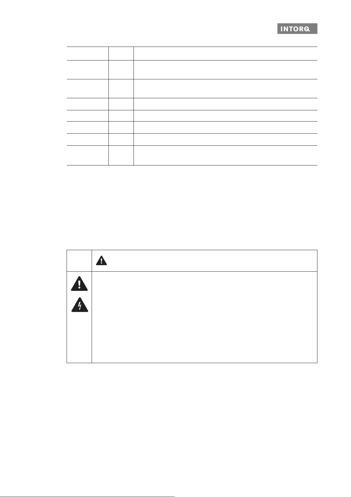
1.5 Safety instructions and notices
The following icons and signal words are used in this document to indicate dangers and important safety information:
Safety instructions
Structure of safety instructions:
equals U
L
SIGNAL WORD
Icon
Indicates the type of danger
Signal word
Characterises the type and severity of danger
Note
Describes the danger
Possible consequences
❚ List of possible consequences if the safety instructions are disregarded.
Protective measure
❚ List of protective measures to avoid the danger.
INTORQ | BA 14.0199 | 08/2016 7
Page 8
Preface and general information
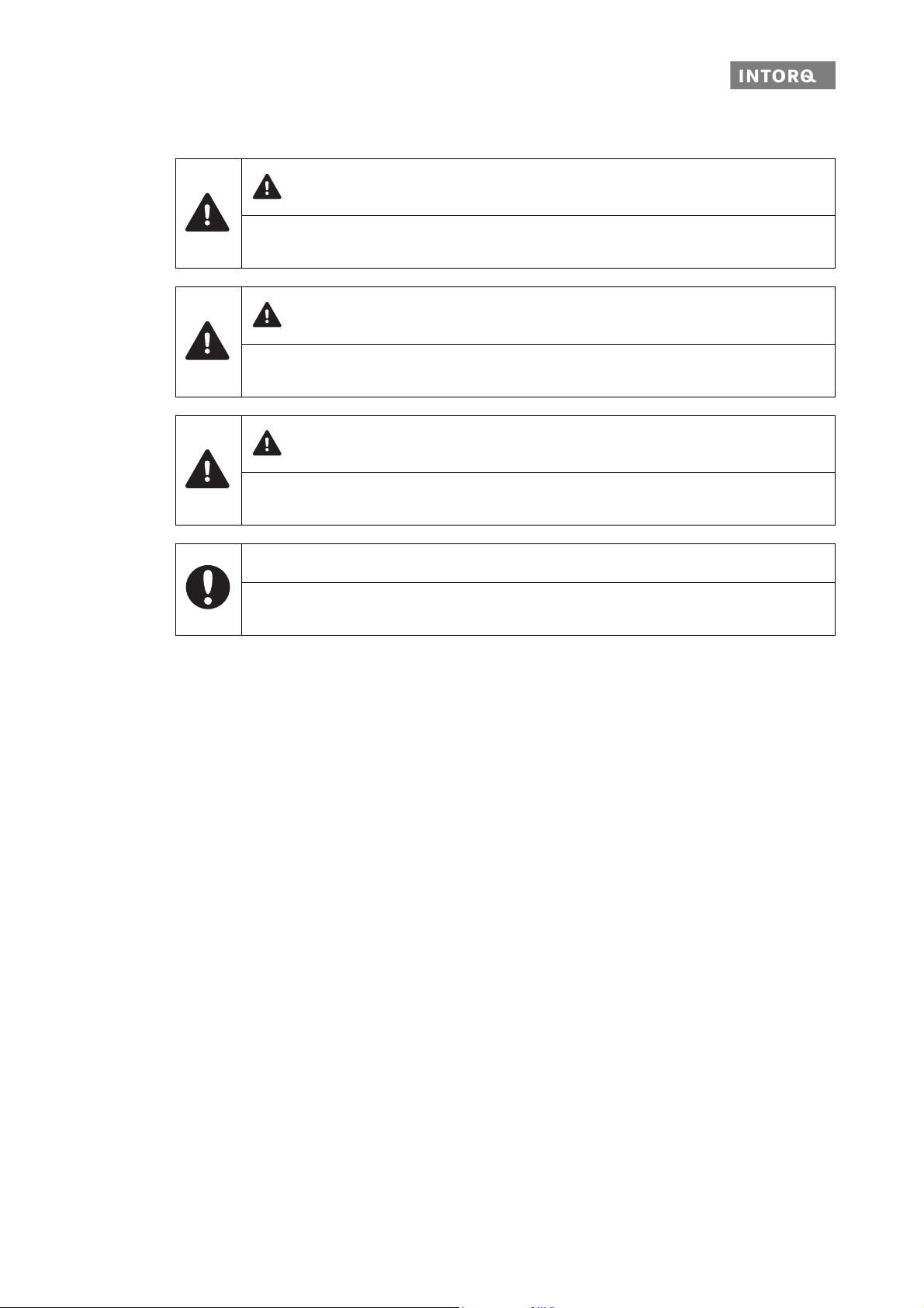
Danger level
DANGER
DANGER indicates a hazardous situation which, if not avoided, will result in death or serious
injury.
WARNING
WARNING indicates a potentially hazardous situation which, if not avoided, could result in
death or serious injury.
CAUTION
CAUTION indicates a hazardous situation which, if not avoided, could result in minor or moderate injury.
NOTICE
Notice about a harmful situation with possible consequences: the product itself or surro unding
objects could be damaged.
1.6 Scope of delivery
After receipt of the delivery, check immediately whether the items delivered match the accompanying papers. INTORQ does not accept any liability for deficiencies claimed subsequently.
❚ Claim visible transport da mage immediately to the deliverer.
❚ Claim visible deficiencies or incomplete deliveries immediately to INTORQ GmbH & Co. KG.
1.7 Disposal
The spring-applied brake consists of different types of material.
❚ Recycle metals and plastics.
❚ Ensure professional disposal of assembled PCBs according to the applicable environmental regulations.
INTORQ | BA 14.0199 | 08/2016 8
Page 9

Preface and general information
1.8 Drive systems
Labelling
Drive systems and components are unambiguously designated by the indications on the name plate.
Manufacturer: INTORQ GmbH & Co. KG, Wülmser Weg 5, D-31855 Aerzen, Germany
1.9 Legal regulations
Liability
❚ The information, data and notes in these Operating Instructions met the state of the art at the time of
printing. Claims referring to drive systems which have already been supplied cannot be derived from this
information, illustrations and descriptions.
❚ We do not accept any liability for damage and operating interference caused by:
- inappropriate use
- unauthorised modifications to the product
- improper work on or with the drive system
- operating errors
- disregarding the documentation
Warranty
❚ Terms of warranty: Refer to the terms of sale and delivery for INTORQ GmbH&Co. KG.
❚ Warranty claims must be made to INTORQ immediately after the defects or faults are detected.
❚ The warranty is void in all cases when liability claims cannot be made.
INTORQ | BA 14.0199 | 08/2016 9
Page 10

Safety instructions
2 Safety instructions
2.1 General safety instructions
❚ INTORQ components ...
- ... must only be used as directed.
- ... must not be commissioned if they are noticeably damaged.
- ... must not be technically modified.
- ... must not be commissioned if they are incompletely mounted or connected.
- ... must not be operated wi thout the required covers.
- ... can hold live as well as moving or rotary parts during operation according to their degree of protection. Surfaces may be hot.
❚ For INTORQ components ...
- ... the documentatio n must always be kept at the installation site.
- ... only permitted accessories are allowed to be used.
- ... only original spare pa rts of the manufacturer are allowed to be used.
❚ Follow all specifications and information found in the corresponding enclosed documentation.
These must be followed to maintain safe, trouble-free operation s and to achieve the specified product
characteristics.
❚ Only qualified, skilled personnel are permitted to work on and with INTORQ components.
According to IEC 60364 or CENELEC HD384, qualified, skilled personnel are persons ...
- ... who are familiar with th e installation, mounting, commissioning, and opera tion of the product.
- ... who have the qualific ations necessary for their occupation.
- ... who know and apply all regulations for the prevention of accidents, directives, and laws relevant
on site.
❚ Risk of burns!
- Surfaces may be hot during opera ti on ! Pro vide for protection against accidental contact.
❚ Risk of injury due to a rotating shaft!
- Wait until the motor is at stan dstill before you start working on the motor.
❚ The friction lining and the friction surfaces must never contact oil or grease since e v en small amounts
reduce the braking torque considerably.
❚ The brake is designed for operation under the environmental conditions that apply to IP66 protecti on.
Because of the numerous possibilities of using the brake, it is however necessary to check the functionality of all mechanical components under the corresponding operating conditions.
INTORQ | BA 14.0199 | 08/2016 10
Page 11

Safety instructions
2.2 Application as directed
❚ INTORQ components ...
- ... are intended for use in machinery and systems.
- ... must only be used for the purposes ordered and confirmed.
- ... must only be operated under the ambient conditions prescribed in these Operating Instructions.
- ... must not be operated beyond their corresponding power limits.
Any other use or excessive usage shall be deemed improper!
Possible applications of the INTORQ spring-applied brake
❚ No explosive or aggressive atmosphere.
❚ Humidity: no restrictions
❚ Ambient temperature:
- Standard desig n: -20 °C to +50 °C
- Optional CCV design: -40 °C to +50 °C
INTORQ | BA 14.0199 | 08/2016 11
Page 12

Technical specifications
3 Technical specifications
3.1 Product description
3.1.1 Structure and function
Abb.1 Design of a BFK470 spring-applied brake
1.1 Stator 3 Complete rotor 10 Socket head cap screw, DIN EN ISO 4762
1.2 Pressure springs 4 Hub 12 Complete manual release (optional)
1.3 Plug (check for air gap) 6 Flange (optional) 30 Setting screw for the factory-set adjustment
of the spring force (sealed), applies only to
sizes 12-18
2 Armature plate 8 Coil X Bore holes are optional
The spring-applied brake is designed for converting mechanical work and kinetic energy into heat energy.
Due to the static braking torque, loads can be held at standstill. Emergency braking is possible at high speed
of rotation. The wear increases as the switching energy increases.
INTORQ | BA 14.0199 | 08/2016 12
Page 13

Technical specifications
The spring-applied brakes BFK470 are electrically releas able single-disc brakes with two friction surfaces.
When de-energized, both of the rotor’s friction surfaces are tightened by the force of the compression springs
between the armature plate and the flange. The braking torque is applied over the friction radius of the rotor;
it is transferred to the shaft via a hub that has axial gear teeth. When the brakes are applied, an air gap "s
is present between the stator and the armature plate. To release the brake, the stator´s coil is energized with
DC voltage. The resulting magnetic flux works against the spring force to draw the armature plate to the stator. This releases the rotor from the spring force and allows it to rotate freely.
3.1.2 Brakes
During the braking procedure, the pressure springs (1.2) use the armature plate (2) to press the rotor (3)
(which can be shifted axially on the hub (4)) against the friction surface. The asbestos-free friction linings
ensure high braking torque and low wear. The braking torque is transmitted between the hub (4) and the rotor
(3) via gear teeth.
NOTICE
Due to the structural design of the stator, the air gap cannot be installed downstream. If the
wear limit is reached, the rotor must be replaced.
"
L
3.1.3 Brake release
When the brakes are applied, an air gap "s
To release the brake, the coil of the stator (1.1) is energ ized with the DC voltage provided. The resulting mag netic flux works against the spring force to draw the armature plate (2) to the stator (1.1). This releases the
rotor (3) from the spring force and allows it to rotate freely
3.1.4 Project planning notes
❚ The brakes are dimensioned in such a way that the given rated torques are reached safely after a short
run-in process.
❚ However, as the organic frictio n linings used do not all have identical properties and because environ-
mental conditions can vary, deviations from the specified braking torques are possible. These must be
taken into account in the form of appropriate dimensioning tolerances. Increased breakaway torque is
common in particular after long downtimes in humid environments where temperatures vary.
❚ If the brake is used as a pure holding brake without dynamic load, the friction lining must be reactivated
regularly.
" is present between the stator (1.1) and the armature pl ate (2).
L
INTORQ | BA 14.0199 | 08/2016 13
Page 14

Technical specifications
3.2 Rated data
Type Max. speed
of rotation
nmax
[rpm]
Temperature
1)
class
Stator
Operating
time
[%]
Moment of
inertia
Rotor
[kgcm2]
without
flange
[kg]
Mass of brake
with
flange
[kg]
without flange
+ Manual
release
[kg]
with flange
+ Manual
release
[kg]
BFK470-06 6000 F (155°C) 100 0.15 1.3 1.5 1.4 1.6
BFK470-08 5000 F (155°C) 100 0.61 2.0 2.2 2.1 2.3
BFK470-10 4000 F (155°C) 10 0 2.0 3.5 3.9 3.7 4.0
BFK470-12 3600 F (155°C) 10 0 4.5 5.0 5.6 5.3 5.8
BFK470-14 3600 F (155°C) 10 0 6.3 7.7 8.5 8.1 8.9
BFK470-16 3600 F (155°C) 100 15.0 11.9 13.1 12.5 13.7
BFK470-18 3600 F (155°C) 100 29.0 17.6 19.1 18.6 20.0
Tab. 1: General brake characteristics
1)
Maximum speed of rotation when installed horizontally (for higher speeds, contact the manufac-
turer)
Type Air gap Rotor thickness
BFK470-06 0.2
BFK470-08 0.2
BFK470-10 0.2
BFK470-12 0.3
BFK470-14 0.3
BFK470-16 0.3
BFK470-18 0.4
Tab. 2: Air gap / rotor thickness
s
LN
[mm]
+0.08
-0.05
+0.08
-0.05
+0.13
-0.05
+0.08
-0.10
± 0.1
+0.15
-0.05
+0.20
-0.10
operating brake
[mm]
s
L max
holding brake
[mm]
operating brake
[mm]
min. New state
0.5 0.3 5.73 5.93
0.5 0.3 6.73 6.93
0.5 0.35 8.73 8.88
0.6 0.45 9.68 9.83
0.75 0.45 9.55 9.85
0.80 0.50 11.05 11.35
1.0 0.65 12.50 12.85
holding brake
[mm] [mm]
6.0
7.0
9.0
10.0
10.0
11.5
13.0
-0.05
-0.05
-0.1
-0.1
-0.1
-0.1
-0.1
INTORQ | BA 14.0199 | 08/2016 14
Page 15
Technical specifications
Type
Outer
diameter
[mm]
Pitch
circle
[mm] Thread
Fixing screws
DIN EN ISO 4762
without flange
[mm]
with flange
[mm]
Minimum thread depth Tightening
torque
without flange
[mm]
with flange
[mm]
M
[Nm]
a
BFK470-06 89 72 M4 3 x M4x40 3 x M4x45 7.5 9.0 3.0
BFK470-08 106 90 M5 3 x M5x45 3 x M5x50 10.5 10.0 5.9
BFK470-10 130 112 M6 3 x M6x55 3 x M6x60 14.0 13.5 10.1
BFK470-12 148 132 M6 3 x M6x60 3 x M6x65 12.5 12.5 10.1
BFK470-14 168 145 M8 3 x M8x75 3 x M8x80 19.5 18.5 24.6
BFK470-16 200 170 M8 3 x M8x80 3 x M8x85 18.0 17.0 24.6
BFK470-18 226 196 M8 6 x M8x90 6 x M10x100 19.5 23.0 24.6
Tab. 3: Installation data
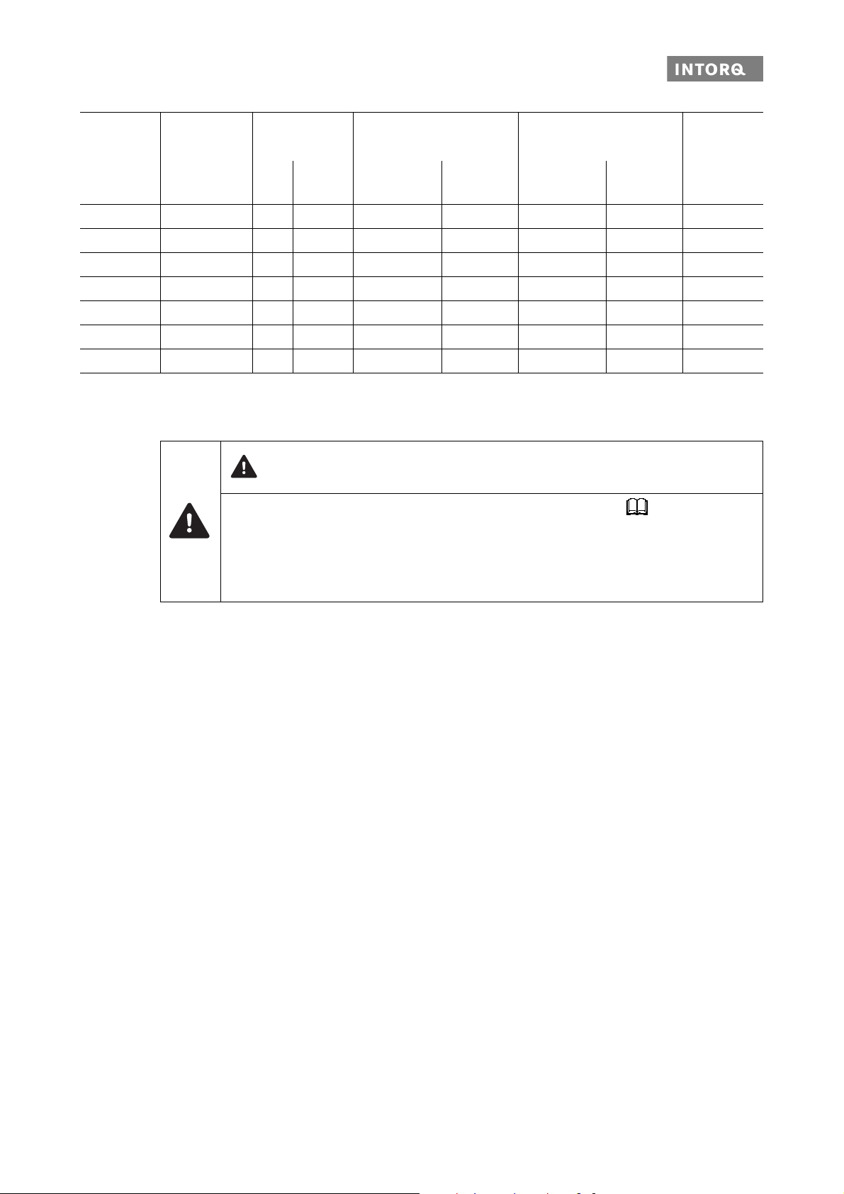
CAUTION
❚ The minimum thread depth of the end shield must be maintained! Tab. 3.
❚ If the required thread depth is no t maintained, the fixing screws may run on to the root. This
has the effect that the required pre-load force is no longer established – the brake is no
longer securely fastened!
❚ The material of the end shield must have a tensile strength of R
>= 250 N/mm2.
m
INTORQ | BA 14.0199 | 08/2016 15
Page 16

Technical specifications
3.3 Rated data (dimensioning data) electrical data
Type Voltage
U [V DC]
BFK470-06
Rated current
[A]
I
N
Power
PN [W]
0.098 20 2101.0
Coil resistance
RN ± 4% []
BFK470-08 0.122 25 1681.0
BFK470-10 0.161 33 1273.0
BFK470-12 0.195 40 1051.0
205
BFK470-14 0.307 60 667.1
BFK470-16 0.332 68 618.0
BFK470-18 0.415 85 494.4
Tab. 4: Coil data at 20°C
Type Braking torques at relative speed of rotation n
Rated torque
[Nm]
100 rpm
Braking torque
X [%] of the rated torque
1500
rpm
3000
rpm
maximum horizontal mounting position
Maximum speed
rpm
BFK470-06 2.0 / 2.5 / 3.0 / 3.5 / 4.0 /
4.5 / 5.5 / 6.0 / 6.5 /
7.0 / 7.5
BFK470-08 3.5 / 5 / 6 / 7 / 8 / 10 /
11 / 12 / 14 / 15
BFK470-10 9 / 11 / 14 / 16 / 18 / 21 /
23 / 25 / 28 / 30 / 33 / 36
BFK470-12 12 / 14 / 15 / 16 / 18 /
23 / 27 / 32 / 36 / 40 /
45 / 46 / 48 / 50 / 55
BFK470-14 40 / 50 / 60 / 65 / 70 /
75 / 80 / 100 / 110
BFK470-16 55 / 80 / 90 / 100 /
105 / 125 / 150
BFK470-18 100 / 150 / 165 / 185 /
200 / 235 / 250
Tab. 5: Rated torques
87 80 74 6000
85 78
83 76 4000
73
5000
81 74
80 73 72
3600
79 72 70
77 70 68
INTORQ | BA 14.0199 | 08/2016 16
Page 17

Technical specifications
Switching times
Abb. 2 Operating/switching times of the spring-applied brakes
t
Engagement time t11Reaction delay of engagement
1
Disengagement time (up to M = 0.1 M
t
2
Rated torque U Voltage
M
dyn
)t
dyn
Rise time of the braking torque
12
Type Rated torque Max. perm.
switching energy
M
K
Q
E
[Nm] [J] [h
Transitional
operating frequency
S
hue
-1
]
Operating times [ms]
at sLN and 0.7 I
DC engagement
t
t
11
12
2)
t
1
1)
N
Disengagement
t
BFK470-06 4 3000 79 16 25 41 32
BFK470-08 8 7500 50 30 26 56 52
BFK470-10 16 12000 40 40 64 104 107
BFK470-12 32 24000 30 47 34 81 121
BFK470-14 60 30000 28 30 47 76 162
BFK470-16 80 36000 27 46 62 109 255
BFK470-18 150 60000 20 62 92 155 343
Tab. 6: Switching energy - operating frequency - operating times
1) Typical values
2) Measured with induced voltage limitation of -800 V DC
2
INTORQ | BA 14.0199 | 08/2016 17
Page 18

Technical specifications
AA
B
Engagement time
The transition from brake-torque free state to holding brakin g torque is not free of time lags.
❚ The engagement time s are valid for DC switching with a spark suppressor.
- Spark suppressors are available for the rated voltages.
- Connect the spark suppressors in parallel to the contact. If this switching is not admissible for safety
reasons (e.g. with hoists and lifts), the spark suppressor can also be connected in parallel to the
brake coil.
- Circuit proposals: 25
❚ The engagement time s are approx. 10 times longer with AC switching.
- Connection: 25
Disengagement time
The disengagement time is the same for DC and AC switchin g. The disengag ement t ime can be shorte ned
by special equipment for fast-response excitation or over-excitation.
3.4 Switching energy / operating frequency
Abb. 3 Switching energy as a function of the operating frequency
Switching energy
Operating frequency
INTORQ | BA 14.0199 | 08/2016 18
Page 19

Technical specifications
S
hmax
S
hue
–
ln 1
Q
R
Q
E
---------
–
--------------------------------=
Q
smaxQE
1e
S
hue
–
S
h
-------------------
–
=
The permissible operating frequency S
set operating frequency S
With high speeds of rotation and switching energy, the wear increases strongly, because very high temperatures occur at the friction surfaces for a short time.
3.5 Emissions
Electromagnetic compatibility
If an INTORQ rectifier is used for the DC switching of the spring-applied brake and if the switching frequency
exceeds five switching operations per minute, the use of a mains filter is required.
If the spring-applied brake uses a rectifier of another manufacturer for the switching, it may become necessary to connect a spark suppressor in parallel with the AC voltage. Spark suppressors are available on request, depending on the coil voltage.
depends on the amount of heat QR (refer to Figure 3). At a pre-
hmax
, the permissible amount of heat is Q
h
smax
.
NOTICE
The user must ensure compliance with EMC Directive 2004/108/EC u sing appro priate contro ls
and switching devices.
Heat
Since the brake converts kinetic energy as well as mechanical and electrical energy into heat, the surface
temperature varies considerably, depending on the operating conditions and possible heat dissipation. Under unfavourable conditions, the surface temperature can reach 130 °C.
Noise
The switching noise during engagement and disengagement varies depending on the air gap, braking torque
and brake size.
Depending on the natural oscillation after installa tion, operating condit ions and state of the frictio n surfaces,
the brake may squeak during braking.
Others
The abrasion of the friction parts produces dust.
INTORQ | BA 14.0199 | 08/2016 19
Page 20

Mechanical installation
4 Mechanical installation
4.1 Important notes
4.1.1 Design of end shield and motor shaft
❚ Comply with the mentioned minimum requirements regarding the end shield and the motor shaft to en-
sure a correct function of the brake.
❚ The diameter of the shaft should er must not be greater than the tooth root diameter of the hub.
❚ The form and position tolerances apply only to the materials mentioned. Contact INTORQ if you are us-
ing other materials.
❚ The brake flange must be supported by the end shield across the full surface.
Design of the end shield
Type Minimum requirements: Use as counter friction surface
Material Evenness Axial runout Roughness Miscellaneous
[mm] [mm]
BFK470-06
BFK470-08
BFK470-10
BFK470-12
BFK470-14
BFK470-16 0.08
BFK470-18 0.10 0.08
Tab . 7: End shield as counter friction surface
S235JR; C15;
EN-GJL-250
0.03
0.05
0.05
without flange with flange
Rz 10 Rz 16
❚ Threaded
holes with
minimum
thread depth
❚ Free of grease
and oil
15
INTORQ | BA 14.0199 | 08/2016 20
Page 21

Mechanical installation
4.1.2 Necessary tools
Type Torque wrench
Measuring range [Nm]
BFK470-06
BFK470-08 4
1 - 12
BFK470-10
BFK470-12
BFK470-14
20 - 100 6 BFK470-16
BFK470-18
* For attaching flange inner bit with pin guide
Multimeter Caliper gauge Feeler gauge
Bit for hexagon socket screws
*
Wrench width [mm]
3
5
INTORQ | BA 14.0199 | 08/2016 21
Page 22

Mechanical installation
4.2 Assembly
4.2.1 Preparation
1. Unpack the spring-applied brake.
2. Check for completeness.
3. Verify the nameplate data (especially the rated voltage).
4.2.2 Brake assembly
NOTICE
The toothed hub and screws must not be lubricated with grease or oil.
Installation of the hub onto the shaft
NOTICE
The customer is responsible for constructing the shaft-hub connection. Make sure that the
bearing length of the key is identical to the length of the hub.
NOTICE
Check the tensile strength of the hub material: When operating with high torque, consult with
INTORQ and use a steel hub with a higher tensile strength.
Abb. 4 Installing the hub onto the shaft
A Circlip B Hub C Keyway
D End shield
1. Press the hub with a moderate amount of force to the shaft.
INTORQ | BA 14.0199 | 08/2016 22
Page 23

Mechanical installation
Secure the hub against axial displacement (for example, by using a circlip).
Mounting the flange
NOTICE
If you are using the spring-applied brake for reverse operations, glue the hub to the shaft.
Abb. 5 Flange and rotor mounting
1. If requ ired, slide the optional flange (6) onto the shaft.
- The chamfer on the flange must point towards the brake!
- Align the through holes of the flange (6) with the fixing holes in the end shield (15).
Abb. 6 Mounting the brake
1Brake 6Flange 15End shield
3 Rotor 10 Socket head cap screws
INTORQ | BA 14.0199 | 08/2016 23
Page 24

Mechanical installation
2. Slide the brake onto the shaft.
- Align supplied so cket head cap screws (10) with fixing holes in the end shield (15).
3. Use a torque key to tighten the socket head cap screws (10) with the required tightening torque, 15.
NOTICE
When using a shaft seal, the brake has to be mounted so that it is centred properly!
The shaft diameter must be implemented in accordance with ISO tolerance h11, with a radial
eccentricity tolerance according to IT8 and an averaged surface roughness of Rz
3.2 µm in
the sealing area.
NOTICE
Please note the following for the version "brake with shaft sealing ring":
❚ Lightly lubricate the lip of the shaft seal with grease.
❚ No grease should be allowed to contact the friction surfaces.
❚ When assembling the stator, push the shaft sealing ring carefully over the shaft. The shaft
should be located concentrically to the shaft seal.
NOTICE
The customer must seal the brake in this position himself if no shaft seal or cover is in use.
NOTICE
If it is necessary to loosen the screws with the seal again, the seals or the complete screw set
must be replaced.
INTORQ | BA 14.0199 | 08/2016 24
Page 25

Electrical installation
5 Electrical installation
5.1 Important notes
DANGER
There is a risk of injury by electrical shock!
❚ Electrical connection must only be carried out by skilled personnel!
❚ Only carry out connection work when no voltage is applied (n o live parts)! There is a risk of
unintended start-ups or electric shock.
NOTICE
❚ It must be ensured that the supply voltage corresponds to the name plate data.
5.2 Electrical connection
Circuit suggestions
NOTICE
The terminal pin sequence shown here does not match the actual order.
INTORQ | BA 14.0199 | 08/2016 25
Page 26

Electrical installation
AA
AA
B
S
AA
AA
B
S
U
U
U
U
U
U
AC switching at the motor – extremely delayed engagement
L1 L2
V
V
L3
4-pole
A
BEG-14x
BEG-24x
BN
3x 39V
BK
R
L
BU
Abb. 7 Supply: Phase-neutral
Bridge rectifiers
BEG-1xx: UN [VDC]=0.9 • [VAC]
Brake
47KΩ
--------
L1 L2
V1U1 W1
U2W2 V2
PNP
v
3
V
V
L3
6-pole
A
BEG-16x
BEG-26x
S
B
U
N
Half-wave rectifiers
v
BEG-2xx: UN [VDC]=0.45 • [VAC]
-------3
Inductive proximity sensor
4-pole
A
BEG-14x
BEG-24x
A
6-pole
BEG-16x
V1U1 W1
U2W2 V2
BEG-26x
Abb. 8 Supply: Phase-phase
1)
Not recommended for most regional/national high-voltage mains systems
BN
3x 39V
BK
R
L
BU
Bridge rectifier
47KΩ
PNP
1)
BEG-1xx: UN [VDC]=0.9 • UV [VAC]
Brake
S
B
U
N
Half-wave rectifiers
BEG-2xx: U
[VDC]=0.45 • UV [VAC]
N
Inductive proximity sensor
INTORQ | BA 14.0199 | 08/2016 26
Page 27

Electrical installation
AA
AA
B
S
AA
AA
B
S
UVU
U
U
U
U
DC switching at the motor – fast engagement
L1 L2
V
L3
BN
3x 39V
BK
R
L
BU
Abb. 9 Supply: Phase-neutral
Bridge rectifiers
BEG-1xx: UN [VDC]=0.9 • [VAC]
Brake
L1 L2
V1U1 W1
U2W2 V2
47KΩ
V
V
L3
PNP
v
-------3
6-pole
BEG-16x
A
BEG-26x
S
B
U
N
Half-wave rectifiers
BEG-2xx: UN [VDC]=0.45 • [VAC]
--------
v
3
Inductive proximity sensor
V1U1 W1
U2W2 V2
BN
3x 39V
BK
R
L
BU
47KΩ
PNP
S
6-pole
BEG-16x
A
BEG-26x
B
U
N
Abb. 10 Supply: Phase-phase
Bridge rectifier
1)
BEG-1xx: UN [VDC]=0.9 • UV [VAC]
Brake
1)
Not recommended for most regional/national high-voltage mains systems
Half-wave rectifiers
BEG-2xx: UN [VDC]=0.45 • UV [VAC]
Inductive proximity sensor
INTORQ | BA 14.0199 | 08/2016 27
Page 28

Electrical installation
AA
AA
B
S
AA
AA
B
S
U
U
AC switching at mains – delayed engagement
V
N
L1
4-pole
BEG-14x
A
BEG-24x
6-pole
BEG-16x
A
BEG-26x
R
L
Abb. 11 Supply: Phase-N
Bridge rectifiers
BEG-1xx: UN [VDC]=0.9 • UV [VAC]
Brake
BN
BK
BU
3x 39V
L1
47KΩ
S
B
U
N
PNP
Half-wave rectifiers
BEG-2xx: UN [VDC]=0.45 • UV [VAC]
Inductive proximity sensor
V
L2
4-pole
BEG-14x
A
BEG-24x
6-pole
A
BEG-16x
BEG-26x
BN
3x 39V
BK
R
L
Abb. 12 Supply: Phase-phase
Bridge rectifier
BU
47KΩ
PNP
1)
S
BEG-1xx: UN [VDC]=0.9 • UV [VAC]
Brake
1)
Not recommended for most regional/national high-voltage mains systems
B
U
N
Half-wave rectifiers
BEG-2xx: UN [VDC]=0.45 • UV [VAC]
Inductive proximity sensor
INTORQ | BA 14.0199 | 08/2016 28
Page 29

Electrical installation
AA
AA
B
S
AA
AA
B
S
U
U
DC switching at mains – fast engagement
V
L2
L1
or
N
L1
6-pole
BEG-16x
A
BEG-26x
BN
3x 39V
BK
R
L
BU
47KΩ
PNP
S
B
U
N
Abb. 13 Supply: Phase-phase or phase-N via 6-pole rectifier
Bridge rectifier
1)
BEG-16x: UN [VDC]=0.9 • UV [VAC]
Brake
1)
For most regional/national high-voltage mains systems, this only makes sense for supplies on L1 and N.
V
L2
L1
or
N
L1
Half-wave rectifiers
BEG-26x: UN [VDC]=0.45 • UV [VAC]
Inductive proximity sensor
4-pole
BEG-14x
A
BEG-24x
14.198.00.xx
BN
3x 39V
BK
R
L
BU
Abb. 14 Supply: Phase-phase or phase-N via 4-pole rectifier
Bridge rectifier
47KΩ
PNP
1)
BEG-14x: UN [VDC]=0.9 • UV [VAC]
Brake
S
B
U
N
Half-wave rectifiers
BEG-24x: U
[VDC]=0.45 • UV [VAC]
N
Inductive proximity sensor
Spark suppressor
14.198.00.xx (required once, select position)
1)
For most regional/national high-voltage mains systems, this only makes sense for supplies on L1 and N.
INTORQ | BA 14.0199 | 08/2016 29
Page 30

Electrical installation
5.3 Technical data for inductive proximity sensors
5.3.1 Proximity sensor for release check
Design PNP, N/O contact
Operating voltage 10 to 30 VDC
Permitted residual ripple 20% U
B
No-load current Max. 10 mA
Output current Max. 200 mA
Voltage drop at outputs Max. 2.0 V at 200 mA
Short circuit protection integrated
Reverse polarity protection integrated
Induction protection integrated
Protection class IP67
Cable configuration and parameters
Cable (diameter / length / AWG) Ø 3.3 mm / L = 2 m / AWG 26
Maximum cable length 100 m
Grey Colour of sheath insulation
Brown (BN) + U
B
Black (BK) Signal (with released armature plate - brake energized)
Blue (BU) - U
B
Operating conditions
Ambient temperature range T
A
from -40 °C to +120 °C (no component damage)
from -25 °C to +120 °C (information analysis)
Shock and vibration IEC 60947-5-2 / 7.4
EMC protection
IEC 60947-5-2 (7.2.3.1) 1 kV
IEC 61000-4-2 Level 2
IEC 61000-4-3 Level 3
IEC 61000-4-4 Level 2
Tab. 8: Technical data for inductive proximity sensors (release check)
INTORQ | BA 14.0199 | 08/2016 30
Page 31

Electrical installation
5.4 Minimum bend radius for the brake connection line
Brake size Wire cross-section Minimum bendradius [mm]
06
08
10
AWG 20 28
12
14
16
AWG 16 46
18
Tab. 9: Minimum bend radius for the brake connection line
5.5 Bridge/half-wave rectifier (optional)
BEG-561- -
The bridge-half-wave rectifiers are used to supply electromagnetic DC spring-applied brakes which are approved for the use with such rectifiers. Other use is only permitted with the approval of INTORQ.
Once a set over-excitation time has elapsed, the bridge-half-wave rectifiers switch over from bridge rectification to half-wave rectification.
Terminals 3 and 4 are located in the DC circuit of the brake. The ind uction voltage peak for DC switching
(see "DC switching - fast engagement" circuit diagram) is limited by an integrated overvoltage protection at
terminals 5 and 6.
5.5.1 Assignment: Bridge/half-wave rectifier – brake size
Rectifier type Supply voltage Over-excitation Holding current reduction
Coil voltage Size Coil voltage Size
[V AC] [V DC] [V DC]
BEG-561-255-030
230 103
BEG-561-255-130 – 14 – 18
BEG-561-440-030-1 400 180 06 – 18 – –
06 – 18
205
06 – 12
INTORQ | BA 14.0199 | 08/2016 31
Page 32

Electrical installation
Abb. 15 BEG-561 attachment options
5.5.2 Technical specifications
Rectifier type Bridge / half-wave rectifier
Output voltage for bridge rectification 0.9 x U
Output voltage for half-wave rectification 0.45 x U
1
1
Ambient temperature (storage/operation) [°C] -25 – +70
Type Input voltage U
(40 Hz – 60 Hz)
Min.
[V ~]
Rated
[V ~]
BEG-561-255-030
1
max.
[V ~]
Max. current I
Bridge
half-wave
[A]
[A]
max
Over-excitation time tue (± 20 %)
at U
1 min
[s]
at U
1 Nom
[s]
at U
[s]
0.430 0.300 0.270
160 230 255 3.0 1.5
BEG-561-255-130 1,870 1,300 1,170
BEG-561-440-030-1 230 400 440 1.5 0.75 0.500 0.300 0.270
1 max
Tab. 10: Data for bridge/half-wave rectifier type BEG-561
U
input voltage (40 – 60 Hz)
1
INTORQ | BA 14.0199 | 08/2016 32
Page 33

Electrical installation
AA
B
C
5.5.3 Reduced switch-off times
AC switching must also be carried out for DC switching (fast engagement)! Otherwise, there will be no overexcitation when it is switched back on.
Delayed engagement Fast engagement
Mains
Bridge
5.5.4 Permissible current load at ambient temperature
1 For screw assembly with metal surface (g ood heat dissipation)
2 For other assembly (e.g. adhesive)
Coil
INTORQ | BA 14.0199 | 08/2016 33
Page 34

Commissioning and operation
6 Commissioning and operation
6.1 Important notes
DANGER
There is a risk of injury by electrical shock!
❚ Electrical connection must only be carried out by skilled personnel!
❚ Only carry out connection work when no voltage is applied (n o live parts)! There is a risk of
unintended start-ups or electric shock.
DANGER
Danger: rotating parts!
The brake must be free of residual torque.
The drive must not be running when checking the brake.
CAUTION
Danger: hot surfaces. Do not touch!
❚ The brake is designed for operation under the environmental conditions that apply to IP66 protecti on.
Because of the numerous possibilities of using the brake, it is however necessary to check the functionality of all mechanical components under the corresponding operating conditions.
NOTICE
Functionality for different operating conditions
❚ The brakes are dimensioned in such a way that the given rated torques are reached safely
after a short run-in process.
❚ However, as the organic friction linings used do not all have identical properties and because
environmental conditions can vary, deviations from the specified braking torques are possible. These must be taken into account in the form of appropriate dimensioning tolerances.
Increased breakaway torque is common, in particular after long downtimes in humid environments where temperatures vary.
NOTICE
Operation without dynamic loads (functioning as a pure holding brake)
❚ If the brake is used as a pure holding brake without dynamic load, the friction lining must be
reactivated regularly.
INTORQ | BA 14.0199 | 08/2016 34
Page 35

Commissioning and operation
6.2 Function checks before commissioning
1. The switching contact for the brake must be open.
2. Remove two bridges from the motor terminals to deenergize the motor.
-Do not disconnect the supply voltage for the brake.
DANGER
There is a risk of electric shock!
If the rectifier is connected to the neutral point of the motor, the neutral conductor must also
be connected to this point.
3. Apply DC voltage to the brake.
4. Measure the AC voltage at the motor terminals. The measured level must be zero.
5. Close the switching contact for the brake.
- The brake is released.
6. Measure the DC voltage at the brake.
- Compare the DC voltage with the voltage indicated on the name plate. A deviation of 10 % is permissible.
- If the measured value deviates: 45
7. Open the switching contact for the brake.
- The brake is applied.
8. Switch off DC voltage for the brake.
9. Screw the bridges onto the motor terminals.
10. If necessary, remove the neutral conductor from the neutral point (step 2).
The preparations for commissioning are completed.
If faults occur, refer to the the error search table, 44. If the fault cannot be fixed or eliminated, please
contact your customer service.
INTORQ | BA 14.0199 | 08/2016 35
Page 36

Commissioning and operation
6.3 Brake with proximity sensor
DANGER
There is a risk of injury by electrical shock!
❚ Electrical connection must only be carried out by skilled personnel!
❚ Only carry out connection work when no voltage is applied (n o live parts)! There is a risk of
unintended start-ups or electric shock.
WARNING
Danger: rotating parts!
The brake must be free of residual torque. The motor must not run!
1. The switching contact for the brake must be open.
2. Remove two bridges from the motor terminals to deenergize the motor.
- Do not switch off the voltage supply to the brake.
- When connecting the rectifier to the neutral point of the motor, the PE conductor must also be connected to this point.
3. Apply DC voltage to the brake.
4. Measure the AC voltage at the motor terminals. The measured level must be zero.
5. Close the switching contact for the brake.
- The brake is released.
6. Measure the DC voltage at the brake:
- Compare the DC voltage with the voltage indicated on the name plate. A deviation of ±10 % is permissible.
7. Check the air gap "s
".
L
- It must be zero and the rotor must rotate freely.
8. Check the switching status of the proximity sensor (refer to Table 11).
9. Open the switching contact for the brake.
- The brake is applied.
10. Check the switching status of the pro ximity sensor (refer to Table 11).
11. Switch off DC voltage for the brake.
12. Screw the bridges onto the motor terminals. Remove additional PE conductor, if necessary.
Contact type Connection Brake released Proximity sensor is closed
N/O contact black / blue no no
Tab. 11: Switching status of the proximity sensor
INTORQ | BA 14.0199 | 08/2016 36
Page 37

Commissioning and operation
6.4 Commissioning
1. Switch on drive system.
2. Carry out a braking test.
6.5 During operation
❚ Checks must be carried out regula rly. Pay special attention to:
- unusual noises or temperatures
- loose fixing elements
- the condition of the electrical cables
- The armature plate must b e attracte d and the rotor must move without residual torque.
❚ Measure the DC voltage at the brake.
- Compare the DC voltage with the voltage indicated on the name plate. A deviation of 10 % is permissible.
❚ If faults occur, refer to the the error search table, 44. If the fault cannot be fixed or eliminated, please
contact your customer service.
INTORQ | BA 14.0199 | 08/2016 37
Page 38

Maintenance and repair
7 Maintenance and repair
7.1 Wear of spring-applied brakes
The table below shows the different causes of wear and their impact on the comp onents of the spring-applied
brake. The influential factors must be quantified so that the service life of the rotor and brake can be calculated and so that the prescribed maintenance intervals can be specified accurat ely. The most important fa ctors in this context are the applied friction energy, the initial speed of rotation of braking and the operating
frequency. If several of the causes of friction lining wear occur in an application at the same time, the influencing factors should be added together when the amount of we ar is calculated.
Component Cause Effect Influencing factors
Friction lining Braking during operation Wear of friction lining Friction work
Emergency stops
Overlapping wear during start and
stop of drive
Active braking via the drive motor
with support of brake (quick stop)
Starting wear in case of motor
mounting position with vertical shaft,
even when the brake is not applied
Armature plate and
counter friction
face
Gear teeth of brake
rotor
Brake support Changing load cycles and shocks in
Springs Axial load cycle and shear stress of
Tab. 12: Causes for wear
Rubbing of brake lining Run-in of armature plate and
Relative movements and shocks
between brake rotor and brake shaft
backlash on reversal between armature plate and cylinder pin
springs through radial backlash on
reversal of armature plate
counter friction face
Wear of gear teeth (primarily
on the rotor side)
Play of armature plate and
cylinder pin
Reduced spring force or
fatigue failure
Number of start/stop
cycles
Friction work
Number of start/stop
cycles
Number of start/stop
cycles, braking torque
Number of switching operations of brake
INTORQ | BA 14.0199 | 08/2016 38
Page 39

Maintenance and repair
7.2 Inspections
7.2.1 Important notes
To ensure safe and trouble-free operations, the spring-applie d brakes must be checked at re gula r intervals
and, if necessary, be replaced. Servicing will be easier at the plant if the brakes are made accessible. This
must be considered when installing the drives in the plant.
Primarily, the required maintenance intervals for industrial brakes result from their load during operation.
When calculating the maintenance interval, a ll causes for wear must be taken into account, 38. For
brakes with low loads (such as holding brakes with emer gency stop function), we recommend a regular inspection at a fixed time interval. To reduce costs, the inspection can be carried out along with other regular
maintenance work in the plant.
Failures, production losses or damage to the system may occur when the brakes are not serviced. Therefore,
a maintenance strategy that is adapted to the particular operating conditions and brake loads must be defined for every application. For the spring-applied brakes, the maintenance intervals and maintenance operations listed in the table below must be followed. The maintenance op erations must be carried out as
described in the detailed descriptions.
7.2.2 Maintenance intervals
Time interval for operating brakes: for holding brakes with emergency
stop:
Inspections with assembled brake
Inspections after removing the brake
❚ according to service life calcula-
tion
❚ or else every six months
❚ after 4000 operating hours at the
latest
❚ Check release function and control
❚ Check rotor
❚ Check hub
❚ Check armature plate and counter friction face
❚ at least every 2 years
❚ after 1 million cycles at the latest
❚ plan shorter intervals for frequent
emergency stops
42
40
INTORQ | BA 14.0199 | 08/2016 39
Page 40

Maintenance and repair
7.3 Maintenance
NOTICE
Brakes with defective armature plates, springs or flanges must be completely replaced.
Observe the following for inspections and maintenance works:
❚ Contamination by oils and greases should be removed using brake cleaner, or the brake
should be replaced after determining the cause. Dirt and particles in the air gap between the
stator and the armature plate endanger the function and should be removed.
❚ After replacing the rotor, the origin al braking torq ue will n ot be reache d until the run -in oper-
ation for the friction surfaces has been completed. Afte r replacing th e rotor, the run-in arma ture plates and the flanges have an increased initial rate of wear.
7.3.1 Check the brake
1. Air gap control (only for sizes12 to 18 ):
- Do not energise the brake when checking the air gap.
- When checking the air gap s
, the plug (item 1.3 in Figure 1) must be levered out manually. Sharp-
L
edged tools will destroy the plug!
- Use a feeler gauge to determine the actual air gap. It can then be compared to the max. permissible
At s
< s
L
air gap s
, the brake remains operational.
Lmax
Lmax
. 14.
NOTICE
After the procedure, the plug (item 1.3) must be pushed in straight so that it is firmly inserted.
Make sure that the plug does not become tilted.
If further tests are required, the brake must be disassembled 41 (only for sizes 6-18).
DANGER
Switch off the voltage. The brake must have no load torque on it when it is being dismantled.
DANGER
There is a risk of injury by electrical shock!
Live connections must not be touched.
WARNING
Danger: rotating parts!
The brake must be free of residual torque. The motor must not run!
INTORQ | BA 14.0199 | 08/2016 40
Page 41

Maintenance and repair
CAUTION
Danger: hot surfaces. Do not touch!
1. Dismantling the brake, 41 .
2. Check rotor: Rotor thickness
- Measure the rotor thickness using a caliper gauge.
- Compare the measured rotor thickness with the minimally permissible rotor thickness, 14.
- If necessary, exchange the roto r.
- Check the gear teeth of the rotor.
- If the gear teeth are damaged, replace the rotor.
7.3.2 Dismantling the brake
Abb. 16 Dismantling the brake
1 Stator 1.2 Shaft seal 1.3 Plug
2 Armature plate 3 Rotor 4 Hub
6 Flange 10 Socket head cap screws 12 Complete manual release
15 End shield
1. Disconnect the connection cable.
2. Loosen the socket head cap screws (10) and remove them.
3. Detach stator (1) from the shaft.
4. Detach rotor (3) from the hub.
5. Check hub: Gear teeth
- Check the gear teeth of the hub.
- If the gear teeth are damaged, dismount and replace the hub.
6. Check armature plate: Thermal damage
- In the case of thermal damage (dark blue tarnishing), replace the stator.
INTORQ | BA 14.0199 | 08/2016 41
Page 42

Maintenance and repair
7. Check counter friction face:
AFlange
- Maximum run-in depth = 30 % of rated air gap 13.
- In the case of strong scoring, repl ace the flange.
- In the case of thermal damage (dark blue tarnishing), replace the flange.
BEnd shield
- Maximum run-in depth = 30 % of rated air gap 13.
- In case of strong scoring, reprocess the end shield 20.
8. Assemble the brake, 22.
9. Connect the supply cable.
10. Recommission the brake, 34.
NOTICE
After replacing the rotor, the original braking torque will not be reached until the run-in operation for the friction surfaces has been completed. After replacing the rotor, the run-in armature
plates and the flanges have an increased initial rate of wear.
7.3.3 Release / voltage
1. Observe the brake functionality while the drive is operating. The armature pl ate must be attracted and
the rotor must move without residual torque.
2. Measure the DC voltage at the brake.
- Compare the DC voltage with the voltage indicated on the name plate. A deviation of 10 % is per-
missible.
INTORQ | BA 14.0199 | 08/2016 42
Page 43

Maintenance and repair
7.4 Spare-parts list
Spring-applied brake INTORQ BFK470-06 to 18
Abb. 17 Spring-applied brake BFK470
_________________ material number of the brake (PLEASE INCLUDE: refer to the nameplate)!
Only parts with item numbers are available.
Item Designation Variant
1.2 Shaft sealing ring Shaft diameter
3 Complete rotor
4 Hub Bore diameter
6 Comple te flange (incl. O-ring)
10 Fixing screws with sealing rings
Socket head cap screw set, DIN EN ISO 4762
7.5 Electrical accessories
Rectifier
Refer to the Operating Instructions "Electrical switching devices and accessories", on page 15.
for mounting to the motor
for flange with through hole
INTORQ | BA 14.0199 | 08/2016 43
Page 44

Troubleshooting and fault elimination
8 Troubleshooting and fault elimination
If any malfunctions should occur during operations, plea se check for possible causes based on the followin g
table. If the fault cannot be fixed or eliminated by one of the listed measures, please contact the customer
service.
Brake malfunctioning
Fault Cause Remedy
Brake does
not release
Coil interruption ❚ Measure coil resistance using a multimeter:
- If resistance is too high, replace the complete stator.
Coil has contact to earth
or between windings
Wiring defective or
wrong
Defective or incorrect
rectifier
❚ Measure coil resistance with multimeter:
- Compare measured value with rated resistance.
- Values: 16
- If resistance is too low, replace the complete stator.
❚ Check coil for short circuit to ground using a multimeter:
- Replace the complete stator if short circuit to ground is detected.
❚ Check brake voltage (refer to "defective rectifier, voltage too low").
❚ Check and correct
- Check cable for continuity using a multimeter:
❚ Replace the complete stator if a cable is defective.
❚ Measure rectifier DC voltage using a multimeter.
If DC voltage is zero:
❚ Check AC rectifier voltage. If AC voltage is zero:
- Switch on power supply
- Check fuse
- Check wiring.
If AC voltage is okay:
- Check rectifier,
- Replace defective rectifier
If DC voltage is too low:
- Check rectifier,
- Diode defective - install an appropriate undamaged rectifier.
❚ Check coil for inter-turn fault or short circuit to ground.
❚ If the rectifier defect occurs again, replace the en tire stator, even if you can-
not find any fault between turns or short circuit to ground. The fault may occur later during heating-up.
Air gap too large
Rotor thickness too
small
INTORQ | BA 14.0199 | 08/2016 44
Replace rotor 41
Replace rotor 41
Page 45

Troubleshooting and fault elimination
Deviations in measured values
Measured value Cause Remedy
Voltage too high Brake voltage does not
match the rectifier
Voltage too low Brake voltage does not
match the rectifier
Defective rectifier diode Replace defective rectifier by a suitable
AC voltage is not mains
voltage
Fuse is missing or defective
Adjust rectifier and brake voltage to each
other.
Adjust rectifier and brake voltage to each
other.
undamaged one.
Install fuse. Exchange fuse.
INTORQ | BA 14.0199 | 08/2016 45
Page 46

Notes
Notes
INTORQ | BA 14.0199 | 08/2016 46
Page 47

Notes
INTORQ | BA 14.0199 | 08/2016 47
Page 48

Notes
INTORQ | BA 14.0199 | 08/2016 48
Page 49

Notes
INTORQ | BA 14.0199 | 08/2016 49
Page 50

Notes
INTORQ | BA 14.0199 | 08/2016 50
Page 51

Page 52

INTORQ GmbH & Co KG
Germany
PO Box 1103
D-31849 Aerzen, Germany
Wülmser Weg 5
D-31855 Aerzen, Germany
+49 5154 70534-444
+49 5154 70534-200
info@intorq.com
应拓柯制动器 (上海)有限责任公司
INTORQ (Shanghai) Co., Ltd.
上海市浦东新区泥城镇新元南路 600 号
6 号楼一楼 B 座
No. 600, Xin Yuan Nan Road,
Building No. 6 / Zone B
Nicheng town, Pudong
201306 Shanghai, China
+86 21 20363-810
+86 21 20363-805
info@cn.intorq.com
INTORQ US Inc.
USA
300 Lake Ridge Drive SE
Smyrna, GA 30082, USA
+1 678 236-0555
+1 678 309-1157
info@us.intorq.com
INTORQ India Private Limited
India
Plot No E-7/3
Chakan Industrial Area, Phase 3
Nighoje, Taluka - Khed
Pune, 410501, Maharashtra, India
+91 2135625500
info@intorq.in
33001439 | BA 14.0199 | EN | 5.0 | © 08/2016 | SC |
www.intorq.com
 Loading...