

INTORQ BFK458, BFK458-06***25, BFK-458-12E, BFK458-25E, BFK458-06 Operating Instructions Manual
...Page 1
INTORQ BFK458
j
setting the standard
Operating Instructions
Electromagnetically-released spring-applied
brake
Phone: 800.894.0412 - Fax: 888.723.4773 - Web: www.actechdrives.com - Email: info@actechdrives.com
Page 2
j | BA 14.0168 | 10/2013
2
This documentation applies to ...
BFK458-06...25
Single version Double version
BFK458XX_XXX.iso/dms BFK458XX_XXX.iso/dms
Product key
Product key INTORQ B FK
-
Legend for the product key INTORQ BFK458
Product group Braking
Product family Spring-applied brake
Type 458
Size 06, 08, 10, 12, 14, 16, 18, 20, 25
Design E - adjustable (brake torque can be reduced via adjuster nut)
N - not adjustable
Not coded: Supply voltage, hub bore, options
Phone: 800.894.0412 - Fax: 888.723.4773 - Web: www.actechdrives.com - Email: info@actechdrives.com
Page 3
j | BA 14.0168 | 10/2013
i
3
Identification
Package label Example
Manufacturer Bar code
Type (see product key) Type-No.
Name
Rated voltage Rated brake torque Qty. per box
Rated power Hub diameter Packaging date
Supplement CE mark
BFK458-017.iso/dms
Nameplate
Content Example
Manufacturer CE marking
BFK458-25E
180V DC 110W 38H7
No.: 15049627 350NM 01.03.05
D - AERZEN
j
Brake type
Rated voltage Rated power Hub diameter
Type no. Rated torque Date of manufacture
Document history
Material number Version Description
405520 1.0 08/1998 TD09 Initial edition for series
405520 1.1 05/2000 TD09 Address revision
Changed values of brake torques in Tab. 1 and Tab. 3
Supplementation of Tab. 4, ”operating times”
460730 2.0 11/2002 TD09 All chapters: Completely revised
Change of company name
Changed values of brake torques
Amendment of drawings, Fig. 12, Fig. 13, Fig. 14, Fig. 15 and Fig. 16
New: Chapter 7.4 ”Spare parts list for double spring-operated brake”
13040626 2.1 02/2005 TD09 Change of company name to INTORQ
13284675 3.0 01/2009 TD09 Change of tightening torques
Supplementation of Tab. 5
Revision of chapter 3.5
Supplementation of chapter 7.1 and 7.2
13284675 3.1 01/2010 TD09 Change of the maintenanceintervals for holding brakes with emergency
stop
13343893 4.0 07/2010 TD09 Values of brake torque and speed modified ( Tab. 3)
13343893 4.1 05/2012 TD 09 Property class of the fixing screws changed
13343893 5.0 10/2013 TD 09 Complete revision
0Fig.0Tab. 0
Phone: 800.894.0412 - Fax: 888.723.4773 - Web: www.actechdrives.com - Email: info@actechdrives.com
Page 4

Contentsi
j | BA 14. 0168 | 10/2013
4
1 Preface and general information 6.......................................
1.1 About these Operating Instructions 6...................................
1.2 Terminology used 6.................................................
1.3 Conventions used 6.................................................
1.4 Abbreviations used 7................................................
1.5 Notes used 8......................................................
1.6 Scope of supply 9..................................................
1.7 Disposal 9........................................................
1.8 Drive systems 9....................................................
1.9 Legal regulations 10.................................................
2 Safety instructions 11...................................................
2.1 General safety information 11..........................................
2.2 Application as directed 12............................................
3Technicaldata 13.......................................................
3.1 Product description 13...............................................
3.2 Characteristics 15..................................................
3.3 Operating times 21..................................................
3.4 Friction work / operating frequency 23..................................
3.5 Emission 24.......................................................
4 Mechanical installation 25................................................
4.1 Overview 25........................................................
4.2 Important notes 25..................................................
4.3 Necessary tools 26..................................................
4.4 Mounting 27.......................................................
4.5 Installation 27......................................................
5 Electrical installation 35.................................................
5.1 Electrical connection 35..............................................
5.2 Bridge/half-wave rectifiers (option) 38...................................
6 Commissioning and operation 41..........................................
6.1 Important notes 41..................................................
6.2 Function checks before commissioning 41................................
6.3 Commissioning 45...................................................
6.4 During operation 45.................................................
Phone: 800.894.0412 - Fax: 888.723.4773 - Web: www.actechdrives.com - Email: info@actechdrives.com
Page 5

Contentsi
i
j | BA 14. 0168 | 10/2013
5
7 Maintenance/repair 47..................................................
7.1 Wear of spring-applied brakes 47.......................................
7.2 Inspections 48......................................................
7.3 Maintenance 48....................................................
7.4 Spare-parts list 52..................................................
7.5 Spare parts order 54................................................
8 Troubleshooting and fault elimination 56...................................
Phone: 800.894.0412 - Fax: 888.723.4773 - Web: www.actechdrives.com - Email: info@actechdrives.com
Page 6

Preface and general information1
j | BA 14.0168 | 10/2013
6
1 Prefaceand generalinformation
1.1 About these Operating Instructions
| These Operating Instructions will help you to work safely on and with the
spring-applied brake with electromagnetic release. They contain safety instructions
that must be followed.
| All persons working on or with the electromagnetically released spring-applied brakes
must have the Operating Instructions available and observe the information and notes
relevant for them.
| The Operating Instructions must always be in a complete and perfectly readable
condition.
1.2 Terminology used
Term In the following text used for
Spring-applied brake Spring-applied brake with electromagnetic release
Drive system Drive systems with spring -applied brakes and other drive
components
1.3 Conventions used
This documentation uses the following conventions to distinguish different types of
information:
Spelling of numbers Decimal separator Point The decimal point is always used.
For example: 1234.56
Symbols
Page reference Reference to another page with additional information
For example: 16 = see page 16
Document reference Reference to another documentation with additional
information
For example: Operating instructions
Wildcard Wildcard for options, selections
For example: BFK458- = BFK458-10
Phone: 800.894.0412 - Fax: 888.723.4773 - Web: www.actechdrives.com - Email: info@actechdrives.com
Page 7

Preface and general information1
i
j | BA 14.0168 | 10/2013
7
1.4 Abbreviations used
Letter symbol Unit Name
I A Current
I
H
A Holding current, at 20 °C and withstand voltage
I
L
A Release current, at 20 °C and release voltage
I
N
A Rated current, at 20 °C and rated voltage
M
A
Nm Tightening torque of the fixing screws
M
K
Nm Characteristic torque of the brake, characteristic value of a relative
speed of 100 rpm
n
max
rpm Maximum occurring speed during the slipping time t3
P
H
W Coil power during holding, at voltage change -over and 20 °C
P
L
W Coil power during release, at voltage change-over and 20 °C
P
N
W Rated coil power, at rated voltage and 20 °C
Q J Quantity of heat/energy
Q
E
J Maximally permissible friction energy for one -time switching,
thermal parameter of the brake
Q
R
J Braking energy, friction energy
Q
Smax
J Maximally permissible friction energy for cyclic switching, depending
on the operating frequency
R
m
N/mm
2
Tensile strength
R
N
Ohms Rated coil resistance at 20 °C
R
z
μm Averaged surface roughness
S
h
1/h Operating frequency, i.e. the number of switching operations evenly
spreadoverthetimeunit
S
hue
1/h Transition operating frequency, thermal parameter of the brake
S
hmax
1/h Maximally permissible operating frequency, depending on the
friction energy per switching operation
s
L
mm Air gap, i.e. lift of the armature plate while the brake is switched
s
LN
mm Rated air gap
s
Lmin
mm Minimum air gap
s
Lmax
mm Maximum air gap
t
1
ms Engagement time, sum of the delay time and braking torque
rise time t
1=t11+t12
t
2
ms Disengagement time, time from switching the stator until reaching
0.1 M
rated
t
3
ms Slipping time, operation time of the brake (according to t11)until
standstill
t
11
ms Delay time during engagement, time from voltage switch -off
to the start of torque rise
t
12
ms Rise time of the braking torque, time from the start of torque rise
until reaching the braking torque
t
ue
s Overexcitation time
U V Voltage
U
H
VDC Withstand voltage, during voltage change-over
U
L
VDC Release voltage, during voltage change-over
U
N
VDC Rated coil voltage; in the case of brakes requiring a voltage
change-over, U
rated
equals U
L
Phone: 800.894.0412 - Fax: 888.723.4773 - Web: www.actechdrives.com - Email: info@actechdrives.com
Page 8

Preface and general information1
j | BA 14.0168 | 10/2013
8
1.5 Notes used
The following pictographs and signal words are used in this documentation to indicate dangers
and important information:
Safety instructions
Structure of safety instructions:
Danger!
Characterises the type and severity of danger
Note
Describes the danger
Possible consequences:
| List of possible consequences if the safety instructions are disregarded.
Protective measure:
| List of protective measures to avoid the danger.
Pictograph and signal word Meaning
Danger!
Danger of personal injury through dangerous electrical voltage
Reference to an imminent danger that may result in death or serious
personal injury if the corresponding measures are not taken.
Danger!
Danger of personal injury through a general source of danger
Reference to an imminent danger that may result in death or serious
personal injury if the corresponding measures are not taken.
Stop!
Danger of property damage
Reference to a possible danger that may result in property damage if the
corresponding measures are not taken.
Application notes
Pictograph and signal word Meaning
Note!
Important note to ensure troublefree operation
Tip!
Useful tip for simple handling
Reference to another documentation
Phone: 800.894.0412 - Fax: 888.723.4773 - Web: www.actechdrives.com - Email: info@actechdrives.com
Page 9

Preface and general information1
i
j | BA 14.0168 | 10/2013
9
1.6 Scope of supply
After receipt of the delivery, check immediately whether it corresponds to the accompanying
papers. INTORQ does not grant any warranty for deficiencies claimed subsequently.
| Claim visible transport damage immediately to the forwarder.
| Claim visible deficiencies / incompleteness immediately to INTORQ GmbH & Co.KG.
1.7 Disposal
The spring-applied brake consists of different types of material.
| Recycle metals and plastics.
| Ensure professional disposal of assembled PCBs according to applicable
environmental regulations.
1.8 Drive systems
Labelling
Drive systems and components are unambiguously designated by the indications on the
nameplate.
Manufacturer: INTORQ GmbH & Co KG, Wülmser Weg 5, D-31855 Aerzen
| The spring-applied INTORQ brakeis also delivered in single modules and individually
combined to its modular design. The data - package labels, nameplate, and type code
in particular - apply to one complete stator.
| If single modules are delivered, the labelling is missing.
Phone: 800.894.0412 - Fax: 888.723.4773 - Web: www.actechdrives.com - Email: info@actechdrives.com
Page 10

Preface and general information1
j | BA 14.0168 | 10/2013
10
1.9 Legal regulations
Liability
| The information, data and notes in this documentation met the state of the art at the
time of printing. Claims referring to products which have already been supplied cannot
be derived from the information, illustrations and descriptions.
| We do not accept any liability for damage and operating interference caused by:
– inappropriate use
– unauthorised modifications to the product
– improper working on and with the product
– operating faults
– disregarding the documentation
Warranty
| Terms of warranty: see terms of sale and delivery of INTORQ GmbH & Co. KG.
| Warranty claims must be made to INTORQ immediately after detecting defects or
faults.
| The warranty is void in all cases where liability claims cannot be made.
Phone: 800.894.0412 - Fax: 888.723.4773 - Web: www.actechdrives.com - Email: info@actechdrives.com
Page 11

Safety instructions2
i
j | BA 14.0168 | 10/2013
11
2 Safetyinstructions
2.1 General safety information
| INTORQ components ...
– ... must only be applied as directed.
– ... must not be commissioned if they are noticeably damaged.
– ... must not be technically modified.
– ... must not be commissioned if they are mounted and connected incompletely.
– ... must not be operated without the required covers.
– ... can hold live as well as moving or rotary parts during operation according to their
degree of protection. Surfaces may be hot.
| For INTORQ components ...
– ... the documentation must always be kept at the installation site.
– ... only permitted accessories are allowed to be used.
– ... only original spare parts of the manufacturer are allowed to be used.
| All specifications of the corresponding enclosed documentation must be observed.
This is vital for a safe and trouble-free operation and for achieving the specified product
features.
| Only qualified, skilled personnel are permitted to work on and with INTORQ
components.
In accordance with IEC 60364 or CENELEC HD 384, qualified, skilled personnel are
persons ...
– ... who are familiar with the installation, mounting, commissioning, and operation of
the product.
– ... who have the qualifications necessary for their occupation.
– ... who know and apply all regulations for the prevention of accidents, directives, and
laws relevant on site.
|Riskofburns!
– Surfaces may be hot during operation! Provide for protection against accidental
contact.
| Risk of injury due to a rotating shaft!
– Wait until the motor is at standstill before you start working on the motor.
| The friction lining and the friction surfaces must by no means have contact to oil or
grease since even small amounts reduce the brake torque considerably.
| The brake is designed for operation under the environmental conditions that apply to
IP54. Because of the numerous possibilities of using the brake, it is however necessary
to check the functionality of all mechanical components under the corresponding
operating conditions.
Phone: 800.894.0412 - Fax: 888.723.4773 - Web: www.actechdrives.com - Email: info@actechdrives.com
Page 12

Safety instructions2
j | BA 14.0168 | 10/2013
12
2.2 Application as directed
| INTORQ components ...
– ... are intended for use in machinery and systems.
– ... must only be used for the purposes ordered and confirmed.
– ... must only be operated under the ambient conditions prescribed in these
Operating Instructions.
– ... must not be operated beyond their corresponding power limits.
Any other use shall be deemed inappropriate!
Possible applications of the INTORQ spring-applied brake
| Humidity: no restrictions
– In case of formation of condensed water and moisture: provide for appropriate
ventilation to ensure that all components will dry quickly.
| Ambient temperature:
– -20 °C to +40 °C (standard)
| At high humidity and low temperature:
– Take measures to protect armature plate and rotor from freezing.
| Protect electrical connections against contact.
Phone: 800.894.0412 - Fax: 888.723.4773 - Web: www.actechdrives.com - Email: info@actechdrives.com
Page 13
Technical data3
i
j | BA 14.0168 | 10/2013
13
3Technicaldata
3.1 Product description
3.1.1 Structure and function
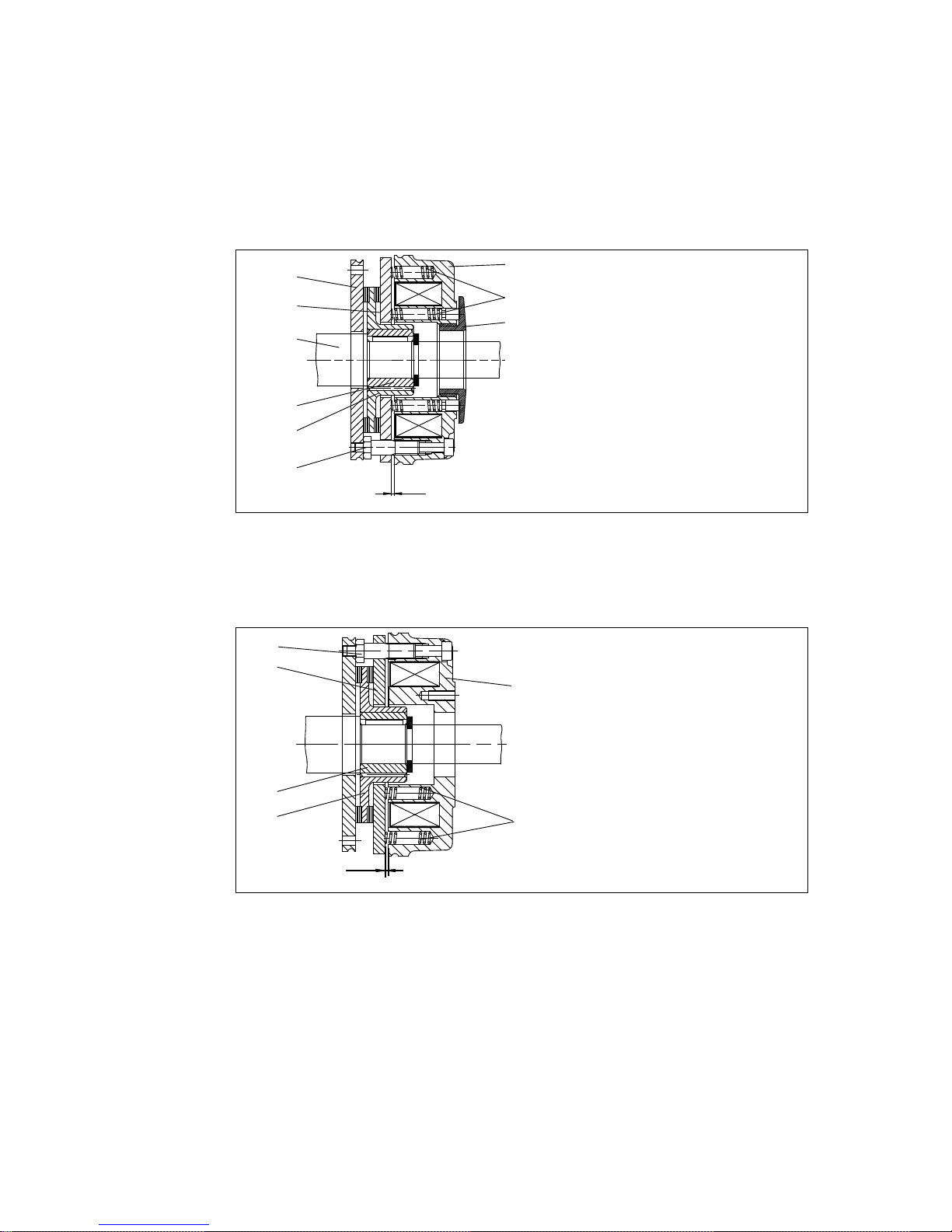
2
1.2
3
4
5
6
31
9
1
s
L
KL 14.0606/1
Fig. 1 Design of the spring-applied brake INTORQ BFK458: basic module E (complete stator) + rotor +
hub + flange
1 Complete stator 3 Rotor 6 Flange
1.2 Compression springs 4 Hub 9 Sleeve bolts
2 Armature plate 5 Shaft 31 Torque adjustment ring
s
L
Air gap
2
1.2
3
4
9
1
s
L
KL 14.0623
Fig. 2 Design of the spring-applied brake INTORQ BFK458: basic module N (complete stator) + rotor +
hub + flange
1 Complete stator 3 Rotor s
L
Air gap
1.2 Compression spring 4 Hub
2Armatureplate 9Sleevebolts
Phone: 800.894.0412 - Fax: 888.723.4773 - Web: www.actechdrives.com - Email: info@actechdrives.com
Page 14

Technical data3
j | BA 14.0168 | 10/2013
14
This spring-applied brake is a single-disk brake with two friction surfaces. The braking torque
is generated by several compression springs (1.2) by friction locking. The brake is released
electromagnetically.
The spring-applied brake INTORQ BFK458- is a single-disk brake with two friction
surfaces. Several compression springs (1.2) create the braking torque by friction locking. The
brake is released electromagnetically.
The spring-applied brake is designed for the conversion ofmechanical work and kinetic energy
into heat. For operating speed, see chapter 3.2 Rated data. Due to the static brake torque,
the brake can hold loads without speed difference. Emergency braking is possible at high
speed, see chapter 3.2 Rated data. The more friction work, the higher the wear.
3.1.2 Braking
During braking the rotor (3) axially slidable on the hub (4) is pressed against the friction
surface by the inner and outer springs (1.2) via the armature plate. The asbestos-free
friction linings ensure a high braking torque and low wear. The braking torque transmission
between hub (4) and rotor (3) is effected by means of toothing.
3.1.3 Brake release
In the braked state, there is an air gap ”s
L
” between the stator (1) and the armature plate (2).
To release the brake, the coil of the stator (1) is excited with the DC voltage provided. The
magnetic force generated attracts the armature plate (2) towards the stator (1) against the
spring force. The rotor (3) is then released and can rotate freely.
3.1.4 Brake torque reduction
For basic module E (adjustable), the spring force and thus the brake torque can be reduced
by unscrewing the adjuster nut (8), ( 46).
3.1.5 Manual release (optional)
The manual release is optionally available for short-term releases when no voltage is applied.
The manual release can be retrofitted.
3.1.6 Microswitch (optional)
The manufacturer offers the microswitch for air-gap or wear monitoring. The user must provide
the corresponding electrical connection ( 35et seqq.).
When air-gap monitoring, the motor does not start before the brake has been released. With
this set-up, all possible faults are monitored. For example, in the event of defective rectifiers,
interrupted connection cables, defective coils, or excessive air gaps the motor will not start.
When checking the wear, no current will be applied to the brake and the motor if the air gap
is too large.
Phone: 800.894.0412 - Fax: 888.723.4773 - Web: www.actechdrives.com - Email: info@actechdrives.com
Page 15

Technical data3
i
j | BA 14.0168 | 10/2013
15
3.1.7 Encapsulated design (optional)
This design not only avoids the penetration of spray water and dust, but also the spreading
of abrasion particles outside the brake. This is achieved by:
| a cover seal over the armature plate and rotor,
| a cover in the adjuster nut,
| a shaft seal in the adjuster nut for continuous shafts (option).
3.1.8 Project planning notes
| The brakes are dimensioned in such a way that the given characteristic torques are
reached safely after a short run-in process.
| Due to the fluctuating properties of the organic friction linings used and the alternating
environmental conditions, deviations of the given braking torques may occur. These
must be considered by corresponding safety measures in the dimensioning process.
Especially with humidity and alternating temperatures, an increased breakaway torque
may occur after a long downtime.
| If the brake is used as a pure holding brake without dynamic load, the friction lining
must be reactivated regularly.
3.2 Characteristics
General data
Stop!
Please observe that engagement times and disengagement times change
depending on the brake torque.
Phone: 800.894.0412 - Fax: 888.723.4773 - Web: www.actechdrives.com - Email: info@actechdrives.com
Page 16
Technical data3
j | BA 14.0168 | 10/2013
16
Size 06 08 10 12 14 16 18 20 25
80 E
Rated torques [Nm],
relating to the
relative speed
Δn = 100 rpm
1.5 E 3.5 N/E 25 N/E 35 N/E 65 N/E 115 N/E 175 N/E
2N/E 4E 7N/E 14 N/E 35 N 45 N/E 80 N/E 145 N/E 220
2.5 N/E 5N/E 9N/E 18 N/E 40 N/E 55 N/E 100 N/E 170 N/E 265 N/E
3N/E 6N/E 11 N/E 23 N/E 45 N/E 60 N/E 115 N/E 200 N/E 300 N/E
3.5 N/E 7N/E 14 N/E 27 N/E 55 N/E 70 N/E 130 N/E 230 N/E 350 N/E
4N/E 8N/E 16 N/E 32 N/E 60 N/E 80 N/E 150 N/E 260 N/E 400 N/E
4.5 N/E 9N/E 18 N/E 36 N/E 65 N/E 90 N/E 165 N/E 290 N/E 445 N/E
5E 10 E 20 E 40 E 75 N/E 100 N/E 185 N/E 315 N/E 490 N/E
5.5 E 11 E 23 N/E 46 N/E 80 N/E 105 N/E 200 N/E 345 N/E 530 N/E
6N/E 12 125 N/E 235 N/E 400 N/E 600 N/E
Tab. 1 N.....Brake torque for module N (without torque adjustment ring)
E......Brake torque for module E (with torque adjustment ring)
Holding brake with emergency stop operation (s
Lmax.
approx. 1.5 x s
Lrated
)
Service brake (s
Lmax.
approx. 2.5 x s
Lrated
)
Standard braking torque
3.2.1 Basic module E, brake torque reduction
For basic module E, the braking torque can be reduced by means of the torque adjustment
ring in the stator. The torque adjustment ring must only be screwed out up to the maximum
projection ”h
Emax.
”, 15 and 46.
Size 06 08 10 12 14 16 18 20 25
Torque reduction
per detent [Nm]
0.2 0.35 0.8 1.3 1.7 1.6 3.6 5.6 6.2
Tab. 2
Phone: 800.894.0412 - Fax: 888.723.4773 - Web: www.actechdrives.com - Email: info@actechdrives.com
Page 17

Technical data3
i
j | BA 14.0168 | 10/2013
17
3.2.2 Brake torques depending on the speed and permissible limit speeds
Type Rated torque at Δn = 100
rpm
Braking torque at Δn0[rpm] [%] max. speed Δn
0max.
with
horizontal mounting position
[%] 1500 3000 maximum [rpm]
BFK458-06
100
87 80 74 6000
BFK458-08 85 78
73
5000
BFK458-10 83 76 4000
BFK458-12 81 74
3600
BFK458-14 80 73 72
IBFK458-16 79 72 70
IBFK458-18 77 70 68
BFK458-20 75 68
66
BFK458-25 73 66 3000
Tab. 3 Brake torques depending on the speed and permissible limit speeds
Type s
LN
+0.1 mm
-0.05 mm
s
Lmax.
Service
brake
s
Lmax.
Holding
brake
Max.
adjustment,
permissible
wear
distance
Rotor thickness Excess
of the torque
adjustment
ring h
Emax.
[mm] [mm] [mm] [mm] min.1)[mm] max. [mm] [mm]
BFK458-06
0.2
0.5 0.3 1.5
4.5 6.0
4.5
BFK458-08 5.5 7.0
BFK458-10 7.5 9.0 7.5
BFK458-12
0.3
0.75 0.45
2.0 8.0
10.0
9.5
BFK458-14 2.5 7.5 11
BFK458-16 3.5 8.0 11.5 10
BFK458-18
0.4
1.0 0.6
3.0 10.0 13.0 15
BFK458-20 4.0 12.0 16.0 17
BFK458-25 0.5 1.25 0.75 4.5 15.5 20.0 19.5
Phone: 800.894.0412 - Fax: 888.723.4773 - Web: www.actechdrives.com - Email: info@actechdrives.com
Page 18

Technical data3
j | BA 14.0168 | 10/2013
18
Type Pitch circle Screws for
flange
mount.
DIN912 8.8
Minimum
depth of
clearing
holes
(mounting
flange)
Tightening torque Weight
of complete
stator
∅[mm] Thread
2)
[mm] Screws [Nm] Complete
lever [Nm]
[kg]
BFK458-06 72 3xM4 3xM4 0.5 3.0
2.8
0.75
BFK458-08 90 3xM5 3xM5 1 5.9 1.2
BFK458-10 112 3xM6 3xM6 2
10.1 4.8
2.1
BFK458-12 132 3xM6 3xM6 3 3.5
BFK458-14 145
3xM8 3xM8
1.5
24.6
12
5.2
BFK458-16 170 0.5 7.9
BFK458-18 196 6xM8 4xM8
3)
0.8
23
12.0
BFK458-20 230
6xM10
4xM10
3)
2.1
48
19.3
BFK458-25 278 6xM10 5 40 29.1
Tab. 4 Characteristics of INTORQ BFK458 spring -applied brake
1) The friction lining is designed such that the brake can be adjusted at least 5 times.
2) The screw length is dependent on the material and the thickness of the mounting surface provided by the customer.
3) The threads are positioned in the mounting surface, offset 30° each to the centre axis of the hand -release lever.
Phone: 800.894.0412 - Fax: 888.723.4773 - Web: www.actechdrives.com - Email: info@actechdrives.com
Page 19

Technical data3
i
j | BA 14.0168 | 10/2013
19
Type Electrical power P
20
1)
Rated current I
N
Release
voltage/holding voltage
U
Coil resistance R20±8%
[W] [A] [V] [Ω]
BFK458-06 20
0.83 24 20
0.21 96 460.8
0.194 103 530.5
0.114 170 1445
0.111 180 1620
0.105 190 1805
0.098 205 2101
BFK458-08 25
1.04 24 23
0.26 89 368
0.242 103 424.4
0.147 170 1156
0.138 180 1296
0.131 190 1444
0.121 205 1681
BFK458-10
30 1.25 24 19.2
31 0.322 96 297.3
32 0.31 103 331.5
30 0.176 170 963.3
32 0.177 180 1013
30 0.157 190 1203
33 0.160 205 1273
BFK458-12 40
1.66 24 14.4
0.41 96 230.4
0.388 103 265.2
0.235 170 722.5
0.222 180 810
0.210 190 902.5
0.195 205 1051
BFK458-14
50
2.08 24 11.5
0.52 96 184.3
53 0.514 103 200.2
50 0.294 170 578
53 0.294 180 611.3
50 0.263 190 722
53 0.258 205 792.9
BFK458-16
55
2.29 24 10.5
0.573 96 167.6
56 0.543 103 189.5
55
0.323 170 525.5
0.305 180 589.1
60 0.315 190 601.7
56 0.292 205 750.5
Phone: 800.894.0412 - Fax: 888.723.4773 - Web: www.actechdrives.com - Email: info@actechdrives.com
Page 20

Technical data3
j | BA 14.0168 | 10/2013
20
Type Electrical power P
20
1)
Rated current I
N
Release
voltage/holding voltage
U
Coil resistance R20±8%
[W] [A] [V] [Ω]
BFK458-18 85
3.54 24 6.8
0.885 96 108.4
0.825 103 124.8
0.5 170 340
0.472 180 387.2
0.447 190 424.7
0.414 205 494.4
BFK458-20
100
4.16 24 5.76
1.04 96 92.2
0.970 103 106.1
0.588 170 289
0.55 180 324
0.487 205 420.3
110 0.578 190 328.2
BFK458-25 110
4.58 24 5.24
1.14 96 83.8
1.06 103 96.5
0.647 170 262.7
0.611 180 294.6
0.578 190 328.2
0.536 205 382.1
Tab. 5 Coil power
1)
Coil power at 20_C
Phone: 800.894.0412 - Fax: 888.723.4773 - Web: www.actechdrives.com - Email: info@actechdrives.com
Page 21

Technical data3
i
j | BA 14.0168 | 10/2013
21
3.3 Operating times
BFKXXX-011.iso/dms
Fig. 3 Operating times of the spring-applied brakes
t
1
Engagement time t
11
Reaction delay during engagement
t
2
Disengagement time (up to M = 0.1 Mr)t12Rise time of the brake torque
M
K
Characteristic torque U Voltage
Type Rated torque at
Δn = 100 rpm
Max. permissible
friction work per
operation only
Transition
operating
frequency
Operating times [ms] at s
LN
and 0.7 I
N
M
r
1
) Q
E
s
hue
DC engagement Disengage
[Nm] [J] [h-1] t
11
t
12
t
1
t
2
BFK458-06 4 3000 79 15 13 28 45
IBFK458-08 8 7500 50 15 16 31 57
BFK458-10 16 12000 40 28 19 47 76
BFK458-12 32 24000 30 28 25 53 115
BFK458-14 60 30000 28 17 25 42 210
BFK458-16 80 36000 27 27 30 57 220
BFK458-18 150 60000 20 33 45 78 270
BFK458-20 260 80000 19 65 100 165 340
BFK458-25 400 120000 15 110 120 230 390
Tab. 6 Switching energy - operating frequency - operating times
1) Minimum braking torque when all components are run in
Phone: 800.894.0412 - Fax: 888.723.4773 - Web: www.actechdrives.com - Email: info@actechdrives.com
Page 22

Technical data3
j | BA 14.0168 | 10/2013
22
Engagement time
The transition from brake-torque free state to holding braking torque is not free of time lags.
Short brake engagement times are vital for emergency braking. DC switching together with
a suitable spark suppressor must therefore be provided.
| The engagement times are valid for DC switching with a spark suppressor.
– Spark suppressors are available for the rated voltages.
– Connect the spark suppressors in parallel to the contact. If this is not admissible for
safety reasons, e.g. with hoists and lifts, the spark suppressor can also be
connected in parallel to the brake coil.
– Circuit proposals: 35
| If the drive system is operated with a frequency inverter so that the brake will not be
deenergised before the motor is at standstill, AC switching is also possible (not
applicable to emergency braking).
Disengagement time
The disengagement time is the same for DC and AC switching. The disengagement times
specified always refer to the control with overexcitation.
Phone: 800.894.0412 - Fax: 888.723.4773 - Web: www.actechdrives.com - Email: info@actechdrives.com
Page 23

Technical data3
i
j | BA 14.0168 | 10/2013
23
3.4 Friction work / operating frequency
10
1
10
2
10
3
10
4
10
5
10 10
2
10
3
10
4
25
20
18
16
14
12
10
08
06
Operating frequency Sh[h-1]
Friction work Q [J]
Sizes
Fig. 4 Friction work as a function of the operating frequency
p
Üã~ñ
=
− p
ÜìÉ
äåN −
n
o
n
b
n
ëã~ñ
= n
b
N − É
−p
ÜìÉ
p
Ü
The permissible operating frequency S
hmax
depends on the quantity of heat QR(see Fig. 4).
If the operating frequency S
h
is specified, the permissible quantity of heat Q
smax
will result.
With high speed and friction work, the wear increases strongly, because very high
temperatures occur at the friction faces for a short time.
Phone: 800.894.0412 - Fax: 888.723.4773 - Web: www.actechdrives.com - Email: info@actechdrives.com
Page 24

Technical data3
j | BA 14.0168 | 10/2013
24
3.5 Emission
Electromagnetic compatibility
Note!
The user must ensure compliance with EMC Directive 2004/108/EC using
appropriate controls and switching devices.
If an INTORQ rectifier is used for the DC switching of the spring-applied brake and if the
operating frequency exceeds five switching operations per minute, the use of a mains filter
is required.
If the spring-applied brake uses a rectifier of another manufacturer for the switching, it
may become necessary to connect a spark suppressor in parallel with the AC voltage.
Spark suppressors are available on request, depending on the coil voltage.
Heat
Since the brake converts kinetic energy as well as mechanical and electrical energy into heat,
the surface temperature varies considerably, depending on the operating conditions and
possible heat dissipation. Under unfavourable conditions, the surface temperature can reach
130 _C.
Noises
The switching noises during engagement and disengagement depend on the air gap ”s
L
”and
the brake size.
Depending on the natural oscillation after installation, operating conditions and state of the
friction faces, the brake may squeak during braking.
Others
The abrasion of the friction parts produces dust.
Phone: 800.894.0412 - Fax: 888.723.4773 - Web: www.actechdrives.com - Email: info@actechdrives.com
Page 25
Mechanical installation4
i
j | BA 14.0168 | 10/2013
25
4 Mechanicalinstallation
4.1 Overview
without separate counter friction
face
with friction plate with flange
BFK458xxxxiso/dms BFK458xxxx.iso/dms BFK458xxxx.iso/dms
4.2 Important notes
Stop!
Toothed hub and screws must not be lubricated with grease or oil!
4.2.1 Design of end shield and motor shaft
| Comply with the mentioned minimum requirements regarding the end shield and the
motor shaft to ensure a correct function of the brake.
| The diameter of the shaft shoulder must not be greater than the tooth root diameter of
the hub.
| The form and position tolerances exclusively apply to the materials mentioned. If other
materials are used, please contact INTORQ.
| The brake flange must be supported by the end shield across the full surface.
Phone: 800.894.0412 - Fax: 888.723.4773 - Web: www.actechdrives.com - Email: info@actechdrives.com
Page 26

Mechanical installation4
j | BA 14.0168 | 10/2013
26
Minimum requirements for end shield:
| Material S235 JR , C15 or EN-GJL-250
– Consult INTORQ if other materials are to be used.
| Evenness
–Size06to12:<0.06mm
– From size 14: < 0.1 mm
| Axial runout 0.10 mm,
| Roughness Rz 10 to Rz 16
| Tensile strength Rm > = 250 N/mm
2
| Drill the threaded holes with the minimum thread depth (dimensions 18).
| The end shield must be free of grease and oil.
The diameter of the shaft shoulder must not be bigger than the tooth root diameter of the hub.
4.3 Necessary tools
Type Torque key
Insert for hexagon socket
screws
Wrench size of open-jawed spanner [mm] Hook wrench
DIN 1810
design A
Box spanner
for flange
installation,
outside
*
Manual
release
Measuring
range [Nm]
Wrench size
[mm]
Sleeve bolts Nuts / bolts 2-flat lever Diameter
[mm]
Wrench size
[mm]
BFK458-06
1to12
3x1/4”
square
8 7/5,5
7
45 - 55
7x1/2”
square
BFK458-08
4x1/4”
square
9
10 / 7
52 - 55
8x1/2”
square
BFK458-10
5 x 1/4”
square
12
68 - 75
10 x1/2”
square
BFK458-12
80 - 90
BFK458-14
20 to 100
6x1/2”
square
15
12 / 8 9
13 x1/2”
BFK458-16 95 - 100
BFK458-18
-/10
10 110 - 115
square
BFK458-20 12 135 - 145
17 x1/2”
square
BFK458-25
8x1/2”
square
17 14 155 - 165
* for flange mounting insertion with journal guide
Phone: 800.894.0412 - Fax: 888.723.4773 - Web: www.actechdrives.com - Email: info@actechdrives.com
Page 27

Mechanical installation4
i
j | BA 14.0168 | 10/2013
27
Feeler gauge Caliper gauge Multimeter
4.4 Mounting
4.4.1 Preparation
1. Unpack spring-applied brake.
2. Check for completeness.
3. Check nameplate data, especially rated voltage.
4.5 Installation
When you have ordered a version with manual release or flange, attach these units first.
4.5.1 Installation of the hub onto the shaft
Note!
The dimensioning of the shaft-hub connection is the responsibility of the
customer. It must be ensured that the bearing length of the keyway is just as
long as the length of the hub.
| Tensile strength of the hub material:
– Size 06 - 16: Tensile strength Rm > 460 N/mm
2
– Size 18 - 25: Tensile strength Rm > 650 N/mm
2
Phone: 800.894.0412 - Fax: 888.723.4773 - Web: www.actechdrives.com - Email: info@actechdrives.com
Page 28

Mechanical installation4
j | BA 14.0168 | 10/2013
28
15
4
4.1
K14.0502/1
Fig. 5 Mounting the hub on the shaft
4 Hub 4.1 Circlip 15 End shield
1. Press the hub (4) on the shaft.
2. Secure the hub against axial displacement, e.g. with a circlip (4.1).
Stop!
For reversing duty we recommend additionally gluing or shrinking the hub onto
the shaft!
4.5.2 Installation of the brake
Assembly of the rotor
3
4
15
K14.0502/8
Fig. 6 Assembly of the rotor
3 Rotor 4 Hub 15 Endshield
1. Push the rotor (3) onto the hub (4) and check whether it can be moved by hand
(Fig. 6).
Phone: 800.894.0412 - Fax: 888.723.4773 - Web: www.actechdrives.com - Email: info@actechdrives.com
Page 29

Mechanical installation4
i
j | BA 14.0168 | 10/2013
29
Stop!
Please note the following for the version ”brake with shaft sealing ring in torque
adjustment ring”:
2. Lightly lubricate the lip of the shaft seal with grease.
3. When assembling the stator (1), push the shaft sealing ring carefully over the shaft.
– The shaft should be located concentrically to the shaft seal.
1
10
15
7
KL458-011-a
Fig. 7 Assembly of the spring-applied brake
1 Complete stator 10 Allen screw
7 Clip 15 Endshield
4. Screw the complete stator (1) onto the end shield (15) using the set of screws (10)
provided and a torque key, (tightening torque 15).
5. Klemmsteine (7) entfernen und entsorgen.
Phone: 800.894.0412 - Fax: 888.723.4773 - Web: www.actechdrives.com - Email: info@actechdrives.com
Page 30

Mechanical installation4
j | BA 14.0168 | 10/2013
30
9
1.1
10
c
KL458-012A
Fig. 8 Torque setting
7 Stator 9 Sleeve bolt { s
LN
10 Cheese head screw
1. Check the air gap near the screws (10) by means of a feeler gauge and compare the
values to the values for ”s
LN
” in the table ( 15).
Note!
Do not insert feeler gauge more than 10 mm between armature plate (2) and
stator (1.1)!
H
J
9
1
10
KL458-013A
Fig. 9 Adjusting the air gap
1 Complete stator 10 Cheese head screw
9 Sleeve bolt
If the measured value ”sL” is outside the tolerance of ”sLN”, set the dimension:
Phone: 800.894.0412 - Fax: 888.723.4773 - Web: www.actechdrives.com - Email: info@actechdrives.com
Page 31
Mechanical installation4
i
j | BA 14.0168 | 10/2013
31
4.5.3 Assembly of the friction plate, sizes 06 to 16
15
27
KL458-009-a
Fig. 10 Mounting the friction plate
15 End shield 27 Friction plate
1. Put a friction plate (27) or flange (6) against the end shield (15).
Note!
The flanged edge of the friction plate must remain visible!
2. Align pitch circle and fastening bore hole thread.
4.5.4 Assembly of the flange
Theflange(6)canbescrewedontheendshield(15)ontheouterpitchcircle(screw
dimensions 15).
Mounting the flange with additional screws
Stop!
| Clearing holes for the screws in the end shield must be behind the threaded
screw drill-holes in the flange. Without the clearing holes, minimal rotor
thickness cannot be utilised. The screws must not press against the end
shield. (See chapter 3.2 for clearing hole depth)
| For sizes 18 and 20, the fastening surface threading must be angled at 30°
to the centre axis to the manual release lever.
Phone: 800.894.0412 - Fax: 888.723.4773 - Web: www.actechdrives.com - Email: info@actechdrives.com
Page 32

Mechanical installation4
j | BA 14.0168 | 10/2013
32
15
6
6.1
KL458-008-a
Fig. 11 Mounting the flange
6 Flange 15 End shield
6.1 Set of fastening screws
1. Hold the flange (6) against the end shield (15) and check the pitch circle and retaining
screw drill hole threading.
2. Fasten the flange (6) on the end shield (15) with the screws (6.1).
3. Tighten the cheese head screws (6.1) evenly, (tightening torques 15).
4. Check the height of the screw heads. The screw heads may not be higher than the
minimum rotor thickness. We recommend using screws according to DIN 6912,
dimensions 15.
Mounting the flange without additional screws
Stop!
When dimensioning the thread depth in the end shield, the permissible wear
distance must be taken into consideration 15).
1. Hold the flange (6) against the end shield (15) and check the pitch circle and retaining
screw drill hole threading.
2. Mount the brake with the set of screws provided for this purpose 28 and 52).
Phone: 800.894.0412 - Fax: 888.723.4773 - Web: www.actechdrives.com - Email: info@actechdrives.com
Page 33

Mechanical installation4
i
j | BA 14.0168 | 10/2013
33
4.5.5 Assembly of the cover seal
15
13
27
10
1
2
12
15
6
13
27
13
10
KL458-010-a KL458-007-a
Fig. 12 Assembly of the cover seal
1 Complete stator 10 Allen screw 15 Endshield
2 Armature plate 13 Cover seal 27 Friction plate
6Flange
1. Insert the cable through the cover ring.
2. Push the cover ring over the stator.
3. Press the lips of the cover ring into the groove of rotor and flange.
– If a friction plate is used, the lip must be pulled over the flanged edge.
Phone: 800.894.0412 - Fax: 888.723.4773 - Web: www.actechdrives.com - Email: info@actechdrives.com
Page 34

Mechanical installation4
j | BA 14.0168 | 10/2013
34
4.5.6 Retrofitting of the manual release
4
14.3
14.2
14.4
3
2
14.5
14.1
1
K14.0630
Fig. 13 Assembly of the manual release BFK458
1. Insert the compression springs (14.2) into the bore holes of the armature plate (2).
2. Push the bolts (14.5) into the bore holes of the shackle (6.1).
3. Push the hexagon head cap screw (14.4) through the compression spring (6.2) in the
armature plate (2) and the bore hole in the stator (1).
4. Screw the hexagon head cap screw (14.4) into the bolts (14.5) in the shackle (14.1).
5. Tighten hexagon screw (14.4) until armature plate (1) moves towards stator (7).
6. Remove the clips (7) (throw away).
7. Adjust gap ”s” and ”s
L”
using the hexagon head cap screw (14.4), (values for ”s” and
”s
L”
see Tab. 7).
Type
1
14 71
sL(mm) s+
0.1
(mm) s+sL(mm)
BFK458-06
0.2
1 1.2
BFK458-08
BFK458-10
BFK458-12
0.3
1.5 1.8
BFK458-14
BFK458-16
BFK458-18
0.4
2 2.4
BFK458-20
BFK458-25 0.5 2.5 3
Tab. 7 Adjustment setting for manual release
Stop!
Dimension ”s” must be observed! Check air gap ”sL”.
Phone: 800.894.0412 - Fax: 888.723.4773 - Web: www.actechdrives.com - Email: info@actechdrives.com
Page 35

Electrical installation5
i
j | BA 14.0168 | 10/2013
35
5 Electricalinstallation
5.1 Electrical connection
5.1.1 Important notes
Stop!
| If emergency switching off is carried out without the required suppressor
circuit, the control unit may be destroyed.
| Observe the correct polarity of the suppressor circuit!
Danger!
| Electrical connection must only be carried out by skilled personnel!
| Connections must only be made when the equipment is de-energised! Danger
through unintended starts or electric shocks.
Stop!
| It must be ensured that the supply voltage corresponds to the nameplate
data.
| Voltages must be adapted to the local environment!
Tip!
Compare the coil voltage of the stator to the DC voltage of the installed rectifier.
5.1.2 Circuit proposals
BFKXXX-007.iso
Bridge rectifier Half-wave rectifier
Fig. 14 Delayed engagement
Phone: 800.894.0412 - Fax: 888.723.4773 - Web: www.actechdrives.com - Email: info@actechdrives.com
Page 36

Electrical installation5
j | BA 14.0168 | 10/2013
36
BFKXXX-002.iso
Bridge rectifier Half-wave rectifier
Fig. 15 Fast engagement
BFKXXX-006.iso
Connection diagram also valid for star connection
DC voltage (e.g. 24V) Spark suppressor
Fig. 16 Separated DC voltage (fast engagement)
Stop!
For switching on the DC side the brake must be operated with a spark
suppressor to avoid impermissible overvoltages.
Phone: 800.894.0412 - Fax: 888.723.4773 - Web: www.actechdrives.com - Email: info@actechdrives.com
Page 37

Electrical installation5
i
j | BA 14.0168 | 10/2013
37
KL-BFKXXX-003.iso
Fig. 17 With microswitch (release check); connection diagram also valid for star connection
DC voltage depending on coil voltage Spark suppressor
KL-BFKXXX-004.iso
Fig. 18 With microswitch / wear check addition for all circuits; connection diagram also valid for star
connection
Phone: 800.894.0412 - Fax: 888.723.4773 - Web: www.actechdrives.com - Email: info@actechdrives.com
Page 38

Electrical installation5
j | BA 14.0168 | 10/2013
38
Tip!
During operation according to Fig. 18 the air gap is only monitored when no voltage is applied
to the brake. This makes sense because it is possible that when the current flows only one
side of the armature plate is attracted at first. This misalignment may cause a simulation of the
maximum air gap and the actuation of the microswitch. If there is no closed contact in parallel
to the microswitch contact, motor and brake will be switched off. The microswitch contact is
closed again when the armature plate is completely released - the release is repeated again because of the small difference-contact travel of the microswitch.
To avoid this misinterpretation of the microswitch signal, the signal should only be processed
when no voltage is applied to the brake.
1. Mount the rectifier in the terminal box. With motors of the insulation class ”H”, mount
the rectifier in the control cabinet. Permissible ambient temperature for the rectifier
-25 _C to +70 _C.
2. Compare the coil voltage of the stator to the DC voltage of the rectifier installed.
Conversion of supply voltage to DC voltage:
– Bridge rectifier: U
DC=UAC
•0.9
– Half-wave rectifier: U
DC=UAC
•0.45
– Permissible deviation of U
coil
and UDCup to ±10%.
3. Select suitable circuit diagram ( 35).
Note!
Selection of the rectifier at voltages ≥ 460 V AC catalogue ”Electronic
switchgear and accessories” Chapter spark suppressors and rectifiers.
4. Motor and brake must be wired according to the requirements of the engagement
time.
5.2 Bridge/half-wave rectifiers (option)
BEG-561- -
Bridge/half-wave rectifiers are used for the supply of electromagnetic spring-applied DC
brakes which have been released for operation with such rectifiers. Any other use is only
permitted with the explicit written approval of INTORQ.
Once a set overexcitation time has elapsed, the bridge/half-wave rectifiers switch over from
bridge rectification to half-wave rectification.
Terminals 3 and 4 are located in the DC circuit of the brake. The induction voltage peak for
DC switching (see ”DC switching - fast engagement” circuit diagram) is limited by an
integrated overvoltage protection at terminals 5 and 6.
Phone: 800.894.0412 - Fax: 888.723.4773 - Web: www.actechdrives.com - Email: info@actechdrives.com
Page 39

Electrical installation5
i
j | BA 14.0168 | 10/2013
39
5.2.1 Assignment: Bridge/half-wave rectifier - brake size
Rectifier type
AC voltage
Overexcitation Holding current reduction
Coil voltage Size Coil voltage Size
[V AC] [V DC] [V DC]
BEG-561-255-030
230
103
06 ... 16
205
06 ... 14
BEG-561-255-130 ----- 16
BEG-561-440-030-1 400 180 06 ... 16 ----- -----
Fig. 19 BEG-561 attachment features
5.2.2 Technical data
Rectifier type Bridge/half-wave rectifier
Output voltage for bridge rectification 0.9 x U
1
Output voltage for half-wave rectification 0.45 x U
1
Ambient temperature (storage/operation) [°C] -25 ... +70
Type Input voltage U
1
(40 Hz ... 60 Hz)
Max. current I
max.
Overexcitation time tue( ±20%)
min.
[V ∼ ]
rated
[V ∼ ]
max.
[V ∼ ]
bridge
[A]
half-wave
[A]
with U
1min
[s]
with U
1
rated
[s]
with U
1
max
[s]
BEG-561-255-030
160
230 255 3.0 1.5
0.430 0.300 0.270
BEG-561-255-130 1.870 1.300 1.170
BEG-561-440-030-1
230
400 440
1.5 0.75 0.500 0.300 0.270
BEG-561-440-130 3.0 1.5 2.300 1.300 1.200
Input voltage U1(40 ... 60 Hz)
Tab. 8 Data for bridge/half-wave rectifier type BEG-561
Phone: 800.894.0412 - Fax: 888.723.4773 - Web: www.actechdrives.com - Email: info@actechdrives.com
Page 40

Electrical installation5
j | BA 14.0168 | 10/2013
40
5.2.3 Reduced switch-off times
When switching on the DC side (fast engagement), switching on the AC side is also required!
Otherwise, there will be no overexcitation during power-on.
Delayed engagement Fast engagement
1234 65
12 3 4 65
Mains Bridge Coil
5.2.4 Permissible current load - ambient temperature
BFKXXX-008.iso
1 For screw assembly with metal surface (good heat dissipation)
2 For other assembly (e.g. glue)
Phone: 800.894.0412 - Fax: 888.723.4773 - Web: www.actechdrives.com - Email: info@actechdrives.com
Page 41

Commissioning and operation6
i
j | BA 14.0168 | 10/2013
41
6 Commissioningand operation
6.1 Important notes
Danger!
The brake must be free of residual torque.
The drive must not be running when checking the brake.
Danger!
Live connections must not be touched.
| The brakes are dimensioned in such a way that the given characteristic torques are
reached safely after a short run-in process.
| Due to the fluctuating properties of the organic friction linings used and the alternating
environmental conditions, deviations of the given braking torques may occur. These
must be considered by corresponding safety measures in the dimensioning process.
Especially with humidity and alternating temperatures, an increased breakaway torque
may occur after a long downtime.
| If the brake is used as a pure holding brake without dynamic load, the friction lining
must be reactivated regularly.
6.2 Function checks before commissioning
6.2.1 Operational check
Brake without microswitch
Danger!
The brake must be free of residual torque. The motor must not rotate.
In the event of failures, refer to the troubleshooting table, 56. If the fault cannot be
eliminated, please contact the aftersales service.
6.2.2 Release / voltage check
For brakes without microswitch only
Danger!
The brake must be free of residual torque. The motor must not rotate.
Phone: 800.894.0412 - Fax: 888.723.4773 - Web: www.actechdrives.com - Email: info@actechdrives.com
Page 42

Commissioning and operation6
j | BA 14.0168 | 10/2013
42
Danger!
Live connections must not be touched.
1. Remove two bridges from the motor terminals. Do not switch off the DC brake supply.
When connecting the rectifier to the neutral point of the motor, the PE conductor must
also be connected to this point.
2. Connect the mains supply.
3. Measure the DC voltage at the brake.
– Compare the DC voltage measured with the voltage specified on the nameplate. A
10 % deviation is permissible.
4. Check air gap ”s
L
”. It must be zero and the rotor must rotate freely.
5. Switch off the current.
6. Bolt bridges to the motor terminals. Remove additional PEN conductor.
Brake with microswitch
Danger!
The brake must be free of residual torque. The motor must not rotate.
Danger!
Live connections must not be touched.
1. The switching contact for the brake must be open.
2. Remove two bridges from the motor terminals t o deenergise the motor.
– Do not switch off the DC brake supply.
– When connecting the rectifier to the neutral point of the motor, the PE conductor
must also be connected to this point.
3. Apply DC voltage to the brake.
4. Measure the AC voltage at the motor terminals. It must be zero.
5. Close the switching contact for the brake.
– The brake is released.
6. Measure the DC voltage at the brake:
– Compare the DC voltage measured with the voltage specified on the nameplate. A
±10 % deviation is permissible.
7. Check air gap ”s
L”
.
– It must be zero and the rotor must rotate freely.
Phone: 800.894.0412 - Fax: 888.723.4773 - Web: www.actechdrives.com - Email: info@actechdrives.com
Page 43

Commissioning and operation6
i
j | BA 14.0168 | 10/2013
43
6.2.3 Microswitch - wear check
Danger!
The brake must be free of residual torque. The motor must not rotate.
Danger!
Live connections must not be touched.
1. Remove two bridges from the motor terminals. Do not switch off the DC voltage for
the brake. When connecting the rectifier to the neutral point of the motor, the PE
conductor must also be connected to this point.
2. Set air gap to ”s
Lmax.
”
.Description 28 worksteps 8-11.
3. Connect the mains supply.
4. Measure the AC voltage at t he motor terminals and the DC voltage at the brake. Both
must be zero.
5. Switch off the current.
6. Set air gap to ”s
LN
”. Description 28 worksteps 8-11.
7. Connect the mains supply.
8. Measure the AC voltage at t he motor terminals. It must be the same as the mains
voltage.
9. Measure the DC voltage at the brake.
– The DC voltage measured after the overexcitation time (see bridge/half-wave
rectifier) must be half the voltage indicated on the nameplate. A 10 % deviation is
permissible.
10. Check air gap ”s
L
”. It must be zero and the rotor must rotate freely.
11. Switch off the current for the brake.
12. Bolt bridges to the motor terminals. Remove additional PEN conductor.
Phone: 800.894.0412 - Fax: 888.723.4773 - Web: www.actechdrives.com - Email: info@actechdrives.com
Page 44
Commissioning and operation6
j | BA 14.0168 | 10/2013
44
6.2.4 Checking the manual release function
Stop!
This operational test is to be carried out additionally!
Danger!
The drive system must be load-free. The motor must not rotate.
Fig. 20 Operating direction of lever
1. Motor and brake de-energised.
2. Pull the lever (Fig. 20) until the resistance increases strongly.
– The rotor must rotate freely. A small residual torque is permissible.
Stop!
Additional tools to facilitate brake release are not allowed! (e.g. extension piece)
3. Release the lever.
–Torquemustbeavailable!
The preparations for commissioning are completed.
In the event of failures, refer to the troubleshooting table, 56. If the fault cannot be
eliminated, please contact the aftersales service.
Phone: 800.894.0412 - Fax: 888.723.4773 - Web: www.actechdrives.com - Email: info@actechdrives.com
Page 45

Commissioning and operation6
i
j | BA 14.0168 | 10/2013
45
6.3 Commissioning
1. Switch on drive system.
2. Carry out a braking test, if necessary, reduce brake torque.
6.4 During operation
Danger!
The running rotor must not be touched.
Danger!
Live connections must not be touched.
| Check the brake regularly during operation. Take special care of:
– unusual noises or temperatures
– loose fixing elements
– the condition of the electrical cables.
| The armature plate must be attracted and the drive must move without residual
torque.
| Measure the DC voltage at the brake.
– Compare the DC voltage measured with the voltage specified on the nameplate. A
±10 % deviation is permissible.
Phone: 800.894.0412 - Fax: 888.723.4773 - Web: www.actechdrives.com - Email: info@actechdrives.com
Page 46

Commissioning and operation6
j | BA 14.0168 | 10/2013
46
6.4.1 Brake torque reduction
h
1max.
31
1
M-
M+
KL458-003-a KL458-006-a
Fig. 21 Reducing the brake torque
1 Complete stator 31 Adjuster nut
1. Turn the adjuster nut (31) counterclockwise using the hook wrench.
– Observe the notches. Positions between notches are impermissible. (Values for the
brake torque reduction see chapter 3.2.1).
– The maximum permissible projection ”h
Emax.
” of the adjuster nut (8) to the stator (1)
is to be observed (values for ”h
Emax.
” see chapter 3.2).
Danger!
The reduction of the brake torque does not increase the maximum permissible
air gap ”s
Lmax.
”.
Do not change the manual release setting for models with manual release.
Phone: 800.894.0412 - Fax: 888.723.4773 - Web: www.actechdrives.com - Email: info@actechdrives.com
Page 47

Maintenance/repair7
i
j | BA 14.0168 | 10/2013
47
7 Maintenance/repair
7.1 Wear of spring-applied brakes
The following table describes the different causes of wear and their effects on the components
of the spring-applied brake. The important influencing factors must be quantified so that the
service life of the rotor and brake can be calculated and that the maintenance intervals to be
prescribed can be specified precisely. The most important factors in this context are the
applied friction energy, the initial speed of braking and the operating frequency. If several of
the causes of friction lining wear occur in an application at the same time, the influencing
factors are to be added together when the amount of wear is calculated.
Component Cause Effect Influencing factors
Friction lining Braking during operation
Wear of friction lining
Friction work
Emergency stops
Overlapping wear during start and
stop of drive
Active braking via the drive motor
with support of brake (quick stop)
Starting wear in case of motor
mounting position with vertical
shaft, even when the brake is not
applied
Number of start/stop cycles
Armature plate and
counter friction face
Rubbing of brake lining Run-in of armature plate and
counter friction face
Friction work
Splining of brake rotor Relative movements and shocks
between brake rotor and brake
shaft
Wear of splining (primarily on the
rotor side)
Number of start/stop cycles
Brake support Load alternation and jerks in the
backlash between armature plate,
sleeve bolts and guide bolt
Breaking of armature plate, sleeve
bolts and guide bolt
Number of start/stop cycles,
braking torque
Springs Axial load cycle and shear stress of
springs through radial backlash on
reversal of armature plate
Reduced spring force or fatigue
failure
Number of switching operations of
brake
Tab. 9 Causes for wear
Phone: 800.894.0412 - Fax: 888.723.4773 - Web: www.actechdrives.com - Email: info@actechdrives.com
Page 48

Maintenance/repair7
j | BA 14.0168 | 10/2013
48
7.2 Inspections
To ensure safe and trouble-free operation, spring-applied brakes must be checked and
maintained at regular intervals. Servicing can be made easier if good accessibility of the
brakes is provided in the plant. This must be considered when installing the drives in the plant.
Primarily, the necessary maintenance intervals for industrial brakes result from the load during
operation. When calculating the maintenance interval, all causes for wear must be taken into
account, ( 47). For brakes with low loads such as holding brakes with emergency stop, we
recommend a regular inspection at a fixed time interval. To reduce the cost, the inspection
can be carried out along with other regular maintenance work in the plant if necessary.
If the brakes are not maintained, failures, production losses or damage to the system may
occur. Therefore, a maintenance concept adapted to the particular operating conditions and
brake loads must be defined for every application. For the spring-applied brakes, the
maintenance intervals and maintenance operations listed in the below table must be provided.
The maintenance operations must be carried out as described in the detailed descriptions.
7.2.1 Maintenance intervals
Designs Service brake Holding brake with emergency stop
BFK458- E/N
BFK458- L
| according to service life
calculation
| otherwise every six months
| after 4000 operating hours at
the latest
| at least every 2 years
| after 1 million cycles at the
latest
| provide shorter intervals with
frequent emergency stops
7.3 Maintenance
Note!
Brakes with defective armature plates, springs or flanges must completely be
replaced.
In general, the following must be observed when carrying out any inspection or
maintenance work:
| Remove impurities through oil and grease using brake cleaning agents, if
necessary, replace brake after identifying the cause of the contamination.
Dirt deposits in the air gap between stator and armature plate impair the
function of the brake and must be removed.
| After the replacement of the rotor, the initial braking torque will not be
reached until the friction surfaces are run in. After the replacement of the
rotor, the run-in armature plates and flanges have a higher initial rate of wear.
In this case, the air gap must be adjusted betimes if necessary.
Phone: 800.894.0412 - Fax: 888.723.4773 - Web: www.actechdrives.com - Email: info@actechdrives.com
Page 49

Maintenance/repair7
i
j | BA 14.0168 | 10/2013
49
7.3.1 Checking the component parts
With assembled brake | Check function of ventilation and control
| Measure the air gap (adjust if necessary)
| Measure the rotor thickness (replace rotor if
necessary)
| Thermal damage to armature plate or flange (dark blue
tarnishing)
50
50
49
After removing the brake | Check clearance of the rotor gearing (replace
worn-out rotors)
| Wear of the torque bearing on threaded sleeves, dowel
pins and armature plate
| Checking springs for damage
| Checking armature plate and flange/endshield
| Evenness size 06...12 < 0.06 mm
| Evenness from size 14 on < 0.1 mm
| max. run-in depth = rated air gap of brake size
51
7.3.2 Checking the rotor thickness
Danger!
When the rotor thickness is checked, the motor must not run.
1. Remove fan cover and cover ring if attached.
2. Measure rotor thickness with calliper g auge. If a friction plate is attached, ensure a
flanged edge at the outer diameter of the friction plate.
3. Compare measured rotor thickness with minimally permissible rotor thickness
(values 15).
4. If required, exchange the entire rotor. Description 51.
7.3.3 Checking the air gap
Danger!
The motor must not be running when checking the air gap.
1. Check the air gap ”s
L
” near the fixing screws between the armature plate and stator
using a feeler gauge ( 15).
2. Compare air gap measured to maximally permissible air gap ”s
Lmax.
”( 15).
3. If required, set air gap to ”s
LN
”( 50).
Phone: 800.894.0412 - Fax: 888.723.4773 - Web: www.actechdrives.com - Email: info@actechdrives.com
Page 50

Maintenance/repair7
j | BA 14.0168 | 10/2013
50
7.3.4 Release / voltage
Danger!
The running rotor must not be touched.
Danger!
Live connections must not be touched.
1. Observe the brake function during operation of the drive. The armature plate must be
attracted and the rotor must move without residual torque.
2. Measure the DC voltage at the brake.
– The DC voltage measured after the overexcitation time (see bridge/half-wave
rectifier) must be half the voltage indicated on the nameplate. A 10 % deviation is
permissible.
7.3.5 Adjusting the air gap
Danger!
The brake must be free of residual torque.
Stop!
Please observe when mounting the flange with additional screws:
Behind the threaded holes for the screws in the flange there must be clearing
holes in the endshield. Without clearing holes the minimum rotor thickness
cannot be used. Under no circumstances may the screws be pressed against
the endshield.
1. Unbolt screws (Fig. 9).
2. Screw the threaded sleeves into the stator by using a spanner.
1
/6revolution reduces
the air gap by approx. 0.15 mm.
3. Tighten screws, torques 15.
4. Check air gap ”s
L
” near the screws using a feeler gauge, ”sLN” 15.
5. If the difference between the measured air gap and ”s
LN
” is too large, repeat the
readjustment.
Phone: 800.894.0412 - Fax: 888.723.4773 - Web: www.actechdrives.com - Email: info@actechdrives.com
Page 51

Maintenance/repair7
i
j | BA 14.0168 | 10/2013
51
7.3.6 Rotor replacement
Danger!
The brake must be free of residual torque.
1. Switch off voltage!
2. Disconnect the supply cable.
3. Loosen the screws evenly and remove them completely.
4. Remove the complete stator from the end shield. Observe the supply cable.
5. Pull the complete rotor off the hub.
6. Check hub teeth.
7. Replace the hub as well if worn.
8. Check the friction surface at the end shield. In case of strong scoring at the flange,
replace the flange. If scoring occurs at the end shield, re-finish end shield.
9. Measure rotor thickness (new rotor) and sleeve bolt head with a caliper gauge.
10. Calculate the gap between the stator and the armature plate as follows:
Gap = rotor thickness + s
LN
- head height
(”s
LN
” 15)
11. Unscrew the sleeve bolts evenly until the calculated gap between stator and armature
plate is reached.
12. Install and adjust new rotor and stator, 28.
13. Reconnect the supply cable.
Phone: 800.894.0412 - Fax: 888.723.4773 - Web: www.actechdrives.com - Email: info@actechdrives.com
Page 52

Maintenance/repair7
j | BA 14.0168 | 10/2013
52
7.4 Spare-parts list
| Only parts with item numbers are available.
– The item numbers are only valid for the standard design.
| Please include the following information with the order:
– Order number of the brake
– Position number of the spare part
13
6
27
3
4
14
10
1
Fig. 22 Spring-applied brake INTORQ BFK458-06 to 25
Pos. Designation Variant
1 Complete stator, module E
Complete stator, module N
Voltage / brake torque
3 Complete rotor
Complete rotor, low-noise version
4Hub Bore
6Flange
Hartchromed flange
10 Set of fastening screws
Allen screw DIN912 8.8
formountingtothemotor/flange
Friction plate:
for flange with through hole
for connection flange / double brake
14 Manual release
13 Cover seal
27 Friction plate
Terminal box as mounting kit
Speedometer flange
Connection flange for double brake
Brake cover (degree of protection corresponds to IP65)
Phone: 800.894.0412 - Fax: 888.723.4773 - Web: www.actechdrives.com - Email: info@actechdrives.com
Page 53

Maintenance/repair7
i
j | BA 14.0168 | 10/2013
53
14
6
1
4
28
12
13
14
3
4
27
10
13
9
5
3
10
1
Fig. 23 Double spring -operated brake INTORQ BFK458-06 to 25
Pos. Designation Variant
1 Complete stator, module N Voltage / brake torque
– as option with noise-reduced armature plate
3 Complete rotor
Aluminium rotor
Aluminium rotor with sleeve
– Low-noise version
4 Hub with standard bore Hole diameter [mm] slot according to DIN 6885/1
5 Set of fastening screws; Allen screw DIN912 8.8 for connection flange / double brake
6Flange
Hartchromed flange
9 Connection flange for double brake
10 Set of fastening screws; Allen screw DIN912 8.8 | for mounting to the flange
| for mounting to the motor / friction plate
| for flange with through hole
12 Cap Basic module N
13 Cover seal
14 Manual release with standard lever Mounting kit
27 Friction plate
28 Shaft seal Shaft diameter on request
Phone: 800.894.0412 - Fax: 888.723.4773 - Web: www.actechdrives.com - Email: info@actechdrives.com
Page 54

Maintenance/repair7
j | BA 14.0168 | 10/2013
54
7.5 Spare parts order
INTORQ BFK458- / complete stator
Size
06 08 10 12 14
16 18 20 25
Design E (with adjuster nut) N (without adjuster nut)
Voltage
24 V 96 V 103 V 170 V 180 V
190 V 205 V
Braking torque ___________ Nm (see torque ranges)
Cable length Standard
___________mm (from 100 mm to 1000 mm in 100 mm steps,
from 1000 mm - 2500 mm in 250 mm steps)
Manual release mounted
Armature plate Standard with washer/brass foil
noise-reduced (O-ring version) hartchromed
Microswitch Monitoring of the switching function (from size 12 on)
Wear monitoring (from size 12 on)
Terminal box mounted (from size 12 on)
Accessories
Rotor
Aluminium Low-noise version (rotor with sleeve)
Plastic (only size 06/08)
Hub _________ mm (for bore diameter, see dimensions)
Set of fixing screws for mounting to the flange
for mounting to the motor / friction plate
for flange with through holes (up to and including size 16)
for connection flange / double brake
Manual release as mounting kit
Terminal box as mounting kit
Flange Friction plate (up to and including size 16)
Flange
Speedometer flange
Connection flange / double brake
Sealing Cover seal
Shaft seal (shaft diameter on request)
Cap
Brake cover
Phone: 800.894.0412 - Fax: 888.723.4773 - Web: www.actechdrives.com - Email: info@actechdrives.com
Page 55

Maintenance/repair7
i
j | BA 14.0168 | 10/2013
55
Electrical accessories
Rectifier type
AC voltage
Overexcitation Holding current reduction
Coil voltage Size Coil voltage Size
[V AC] [V DC] [V DC]
BEG-561-255-030
230
103
06 ... 16
205
06 ... 14
BEG-561-255-130 ----- 16
BEG-561-440-030-1 400 180 06 ... 16 ----- -----
Phone: 800.894.0412 - Fax: 888.723.4773 - Web: www.actechdrives.com - Email: info@actechdrives.com
Page 56

Troubleshooting and fault elimination8
j | BA 14.0168 | 10/2013
56
8 Troubleshootingandfault elimination
If any malfunctions should occur during operation, please check the possible causes using the
following table. If the fault cannot be eliminated by one of the listed measures, please contact
the aftersales service.
Fault Cause Remedy
Brake cannot be released, air gap is
not zero
Coil is interrupted | Measure coil resistance using multimeter:
– If the resistance is too high replace the stator.
Coil has interturn fault or short circuit to
ground
| Measure coil resistance using multimeter:
– Compare measured resistance to rated
resistance. For values, 15. If the resistance
is too low, replace the entire stator.
| Test the coil for short circuit to ground using a
multimeter:
– If a short circuit to ground occurs, replace the
stator.
| Check the brake voltage (see defective rectifier,
voltage too low).
Defective or wrong wiring | Check and correct wiring.
| Checkthecableusingamultimeter:
– Replace defective cable
Defective or wrong rectifier | Measure the DC voltage at the rectifier using a
multimeter.
When the DC voltage is zero:
| Measure the AC voltage at the rectifier.
When the AC voltage is zero:
– Apply voltage
–Checkfuse
–Checkwiring
When the AC voltage is ok:
– Check rectifier
– Replace defective rectifier
When the DC voltage is too low:
– Check rectifier
– If diode is defective, use suitable new rectifier
| Check the coil for fault between turns a nd short
circuit to ground.
| If the rectifier defect occurs again, replace the
entire stator, even if you cannot find any fault
between turns or short circuit to ground. The fault
may occur later during heating-up.
Incorrect wiring of microswitch Check the wiring of the microswitch and correct it.
Incorrect setting of microswitch Replace the stator and complain about the micro
switch quality at the manufacturer
Air gap too big Readjust the air gap, 50
Rotor cannot rotate freely
Wrong setting of manual release Check dimension s+sLwith energised brake. The
dimension must be identical at both sides. Correct if
necessary.
Air gap sLtoo small Check air gap sLüand readjust it, if necessary 50.
Phone: 800.894.0412 - Fax: 888.723.4773 - Web: www.actechdrives.com - Email: info@actechdrives.com
Page 57

Troubleshooting and fault elimination8
i
j | BA 14.0168 | 10/2013
57
RemedyCauseFault
Rotor not thick enough Rotor has not been replaced in time Replace rotor, 51
Voltage is not zero when checking
the operation 41
Incorrect wiring of microswitch Check the wiring of the microswitch and correct it.
Defective microswitch or incorrect
setting
Replace the stator and send the defective stator to
the manufacturer.
Voltage too high Brake voltage does not match the
rectifier
Adapt rectifier and brake voltage to each other.
Voltage too low
Brake voltage does not match the
rectifier
Adapt rectifier and brake voltage to each other.
Defective rectifier diode Replace rectifier by a suitable new one.
AC voltage is not mains voltage
Fuse missing or defective Select a connection with proper fusing.
Incorrect wiring of microswitch Check the wiring of the microswitch and correct it.
Defective microswitch or incorrect
setting
Replace the entire stator and return it to the
manufacturer.
Phone: 800.894.0412 - Fax: 888.723.4773 - Web: www.actechdrives.com - Email: info@actechdrives.com
 Loading...