

Page 1
www.intorq.com
setting the standard
www.intorq.com
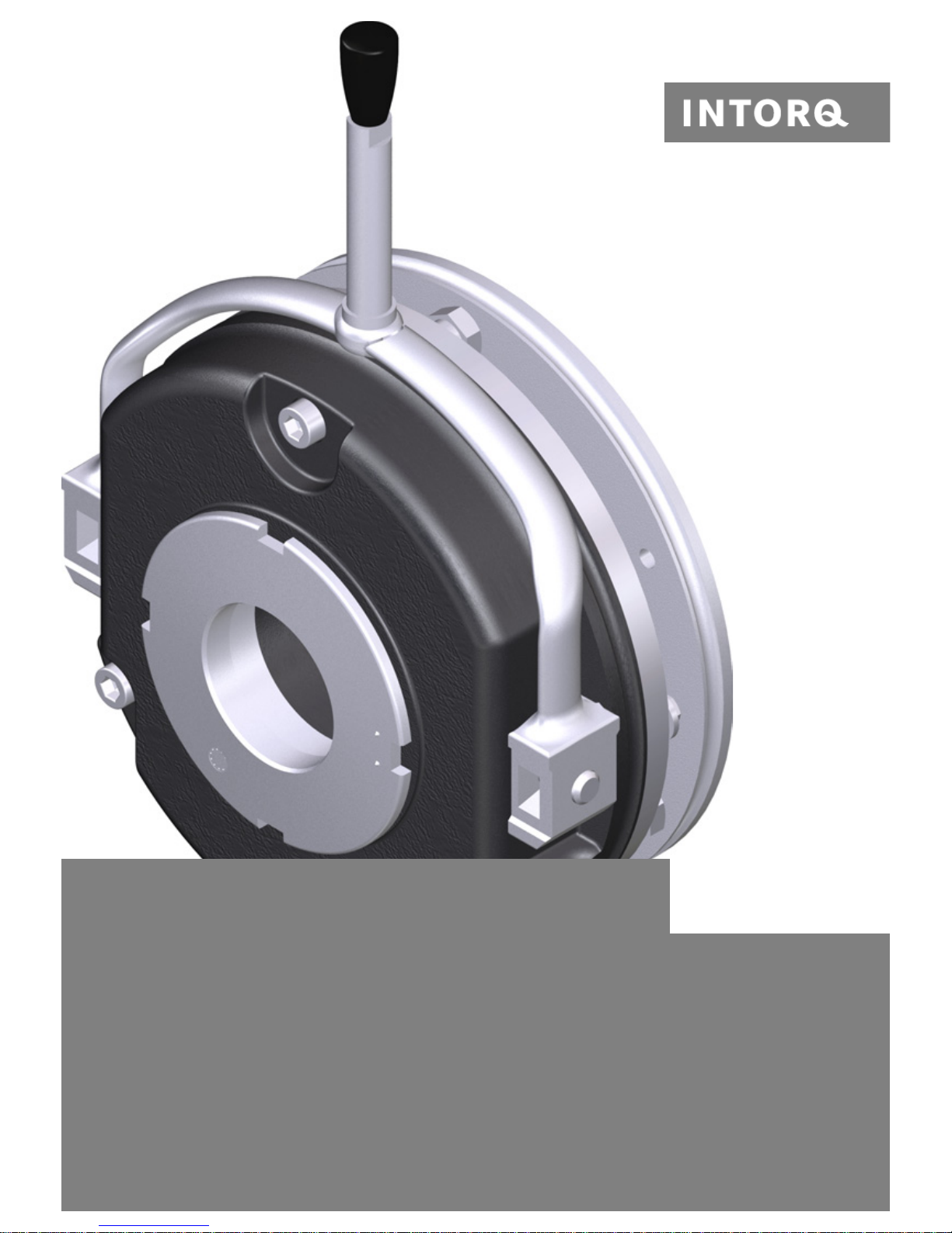
INTORQ BFK458
Electromagnetically Released Spring-Applied Brake
Translation of the Original Operating Instructions
Page 2
INTORQ | BA 14.0168 | 09/2015 2
Document history
Legal regulations
Liability
❚ The information, data and notes in these Operating Instructions met the state of the art at the time of
printing. Claims referring to drive systems which have already been supplied cannot be derived from this
information, illustrations and descriptions.
❚ We do not accept any liability for damage and operating interference caused by:
- inappropriate use
- unauthorised modifications to the product
- improper work on or with the drive system
- operating errors
- disregarding the documentation
Material number Version Description
405520 1.0 08/1998 TD09 First edition for the series
405520 1.1 05/2000 TD09 Address revision
Changed values of brake torques, table 1 and table 3
Supplemented table 4, switching times
460730 2.0 11/2002 TD09 All chapters: Complete editorial revision
Changed company name
Changed values of brake torques
Changed drawings: Fig. 12, Fig. 13, Fig. 14, Fig.15 and Fig. 16
New: Chapter 7.4 "Spare parts list for double spring-operated brake"
13040626 2.1 02/2005 TD09 Changed company name to INTORQ
13284675 3.0 12/2008 TD09 Changed the tightening torques
Supplemented table 5
Revision of Chapter 3.5
Supplemented Chapters 7.1 and 7.2
13284675 3.1 01/2010 TD09 Changed the maintenance intervals for holding brake s with emergency
stop
13343893 4.0 07/2010 TD09 Changed values of the braking torques and rotation speeds
( table 3)
13343893 4.1 05/2012 TD09 Changed strength grade of the fixing screws
13343893 5.0 10/2013 TD09 Complete revision
13343893 6.0 09/2015 SC Restructured FM, harmonized connection diagrams, revised graphics
Page 3
INTORQ | BA 14.0168 | 09/2015 3
Warranty
❚ Warranty claims must be made to INTORQ immediately after the defects or faults are detected.
❚ The warranty is void in all cases when liability claims cannot be made.
Spring-applied brakes of type BFK458-06...25
NOTICE
The warranty conditions can be found in the terms and conditions of INTORQ GmbH & Co. KG.
Design E Design N
Doubled design N
Page 4

INTORQ | BA 14.0168 | 09/2015 4
Product key
Not coded: Supply voltage, hub bore, options
Checking the delivery
After receipt of the delivery, check immediately whether the items delivered match the accompanying papers. INTORQ does not accept any liability for deficiencies claimed subsequently.
❚ Claim visible transport damage immediately to the deliverer.
❚ Claim visible deficiencies or incomplete deliveries immediately to INTORQ GmbH & Co. KG.
INTORQ B FK -
Product group: Brake
Product type Spring-applied brake
Type: 458
Size: 06, 08, 10, 12, 14, 16, 18, 20, 25
Design/type:
E - adjustable (brake torque can be reduced via adjuster nut)
N - not adjustable
L - not adjustable, LongLife design
NOTICE
Labelling of drive systems and individual components
❚ Drive systems and components are unambiguously designated by the labelling on their
nameplates.
❚ The INTORQ spring-applied brake is also delivered in single modules which can then be put
together by the customer according to their requirements. The specifications – particularly
the packaging label, nameplate and type code – apply to a complete stator .
❚ The labelling is not included when modules are delivered individually.
Page 5

INTORQ | BA 14.0168 | 09/2015 5
Contents
1 General information ................................................................................................................................................7
1.1 Using these operating instructions.................................................................................................................7
1.2 Conventions in use.........................................................................................................................................7
1.3 Safety instructions and notices......................................................................................................................8
1.4 Terminology used........................................................................... .... .... ........................................................9
1.5 Abbreviations used.........................................................................................................................................9
2 Safety instructions ................................................................................................................................................11
2.1 General safety instructions...........................................................................................................................11
2.2 Disposal.......................................................................................................................................................11
3 Product description...............................................................................................................................................12
3.1 Application as directed.................................................................................................................................12
3.2 Layout..........................................................................................................................................................12
3.2.1 Basic module E ................................................................................................................................12
3.2.2 Basic module N ................................................................................................................................13
3.2.3 Basic module L ................................................................................................................................13
3.2.4 Basic module N, doubled design .....................................................................................................14
3.3 Optional configuration..................................................................................................................................15
3.3.1 Manual release (optional) ................................................................................................................15
3.3.2 Optional microswitch ........................................................................................................................15
3.3.3 Optional encapsulated design ..........................................................................................................15
3.3.4 Optional CCV ...................................................................................................................................15
4 Technical specifications.......................................................................................................................................16
4.1 Brake torque reduction.................................................................................................................................16
4.2 Rated data....................................................................................................................................................17
4.3 Switching times............................................................................................................................................22
4.4 Switching energy / switching frequency......................................................................... .... .... ......................24
4.5 Electromagnetic compatibility.......................................................................................................................25
4.6 Emissions.....................................................................................................................................................25
4.7 Manual release.............................................................................................................................................26
4.8 Labels on product.........................................................................................................................................27
5 Mechanical installation .........................................................................................................................................29
5.1 Tools............................................................................................................................................................30
5.2 Preparing the installation............................................................................ ..................................................30
5.3 Installing the hub onto the shaft...................................................................................................................31
5.4 Installing the brake.......................................................................................................................................32
5.5 Installing the friction plate (optional).............................................................................................................34
5.6 Mounting the flange......................................................................................................................................34
5.6.1 Mounting the flange without additional screws ................................................................................34
5.6.2 Installing the flange (variants: size 06) .............................................................................................35
5.6.3 Installing the flange (variants: sizes 18 – 20) ...................................................................................36
5.6.4 Installing the flange (variants: size 25) .............................................................................................37
5.7 Installing the double-rotor brake...................................................................................................................38
5.8 Cover ring assembly ....................................................................................................................................39
5.9 Installing the shaft seal.................................................................................................................................40
5.10 Installing the manual release (retrofitting) ...................................................................................................41
Page 6

INTORQ | BA 14.0168 | 09/2015 6
6 Electrical installation.............................................................................................................................................42
6.1 Electrical connection.......................................................................... ..........................................................42
6.2 AC switching at the motor – extremely delayed engagement......................................................................43
6.3 DC switching at the motor – fast engagement.............................................................................................44
6.4 AC switching at mains – delayed engagement............................................................................................45
6.5 DC switching at mains – fast engagement...................................................................................................46
6.6 Technical specifications for the microswitch................................................................................................47
6.7 Bridge/half-wave rectifier (optional)..............................................................................................................47
6.7.1 Assignment: Bridge/half-wave rectifier – brake size ........................................................................48
6.7.2 Technical specifications ................................................................................. .... .... ..........................49
6.7.3 Reduced switch-off times .................................................................................................................49
6.7.4 Permissible current load at ambient temperature ............................................................................50
7 Commissioning and operation.............................................................................................................................51
7.1 Protect the electrical connections against any contact or touching..............................................................51
7.2 Function checks before commissioning.......................................................................................................52
7.2.1 Function check of brake without microswitch ...................................................................................52
7.2.2 Release / voltage check for brakes without microswitch ..................................................................52
7.2.3 Release / voltage check for brakes with microswitch .......................................................................52
7.2.4 Microswitch – checking for wear ......................................................................................................53
7.2.5 Test that the manual release functions ............................................................................................54
7.3 Commissioning.............................................................................................................................................55
7.4 Operation.....................................................................................................................................................55
7.4.1 Brake torque reduction .....................................................................................................................56
8 Maintenance and repair ........................................................................................................................................57
8.1 Wear of spring-applied brakes.....................................................................................................................57
8.2 Inspections...................................................................................................................................................58
8.2.1 Maintenance intervals ......................................................................................................................58
8.3 Maintenance.................................................................................................................................................58
8.3.1 Checking the component parts ........................................................................................................59
8.3.2 Check the rotor thickness .............................................. .... .... .... ......................................................59
8.3.3 Check the air gap ................................................................................................... ..........................59
8.3.4 Release / voltage .............................................................................................................................60
8.3.5 Adjusting the air gap ........................................................................................................................60
8.3.6 Replacing the rotor ............................................................. .... ..........................................................61
8.4 Spare-parts list.............................................................................................................................................62
9 Troubleshooting and fault elimination ................................................................................................................64
Page 7
General information
INTORQ | BA 14.0168 | 09/2015 7
1 General information
1.1 Using these operating instructions
❚ These Operating Instructions will help you to work safely with the spring-applied brake with electromag-
netic release. They contain safety instructions that must be followed.
❚ All persons working on or with the electromagnetica lly released spring-applied brakes must have t he Op-
erating Instructions available and observe the information and n otes relevant for them.
❚ The Operating Instructions must always be in a complete and perfectly read able condition.
1.2 Conventions in use
This document uses the following styles to distinguish between different types of info rmation:
Spelling of numbers
Decimal separator Point The decimal point is always used. For exam-
ple: 1234.56
Symbols
Page reference Reference to another page with additional
information
For example: 16 = refer to page 16
Wildcard Wildcard for options, selections
For example: BFK458- = BFK458-10
Note
Important notice about ensuring smooth
operations or other key information.
Page 8
General information
INTORQ | BA 14.0168 | 09/2015 8
1.3 Safety instructions and notices
The following icons and signal words are used in this document to indicate dangers and important safety information:
Safety instructions
Structure of safety instructions:
Danger level
SIGNAL WORD
Icon
Indicates the type of danger
Signal word
Characterizes the type and severity of danger
Note
Describes the danger
Possible consequences
❚ List of possible consequences if the safety instructions are disregarded
Protective measure
❚ List of protective measures to avoid the danger
DANGER
DANGER indicates a hazardous situation which, if not avoided, will result in death or serious
injury.
WARNING
WARNING indicates a potentially hazardous situation which, if not avoided, could result in
death or serious injury.
CAUTION
CAUTION indicates a hazardous situation which, if not avoided, could result in minor or moderate injury.
NOTICE
Notice about a harmful situation with possible consequences: the product itself or surroun ding
objects could be damaged.
Page 9

General information
INTORQ | BA 14.0168 | 09/2015 9
1.4 Terminology used
1.5 Abbreviations used
Term In the following text used for
Spring-applied brake Electromagnetically Released Spring-Applied Brake
Drive system Drive systems with spring-applied brakes and other drive components
Cold Climate Version (CCV) Version of the sp ring-operated brake suited for particularly low temper-
atures
Letter symbol Unit Designation
I A Current
I
H
A Holding current, at 20 °C and holding voltage
I
L
A Release current, at 20 °C and release voltage
I
N
A Rated current, at 20 °C and rated voltage
M
A
Nm Tightening torque of fixing screws
M
K
Nm
Rated torque of the brake, rated value at a relative speed of rotatio n of 100 rpm
n
max
rpm Maximum occurring speed of rotation during the slipping time t
3
P
H
W Coil power during holding, after voltage change-over and 20 °C
P
L
W Coil power during release, before voltage change-over and 20 °C
P
N
W Rated coil power, at rated voltage and 20 °C
Q J Quantity of heat/energy
Q
E
J Max. permissible friction energy for one-time switching, thermal parame ter of
the brake
Q
R
J Braking energy, friction energy
Q
Smax
J Max. permissible friction energy for cyclic switching, depending on the switch-
ing frequency
R
m
N/mm
2
Tensile strength
R
N
Ohms Rated coil resistance at 20 °C
R
z
µm Average surface roughness
S
h
1/h Operating frequency: the number of switching operations evenly spread over
the time unit
S
hue
1/h Transition switching frequency, thermal parameter of the brake
S
hmax
1/h Maximum permissible switching frequency, depending on the friction energy
per switching operation
s
L
mm Air gap: the lift of the armature plate while the brake is switched
s
LN
mm Rated air gap
s
Lmin
mm Minimum air gap
Page 10

General information
INTORQ | BA 14.0168 | 09/2015 10
s
Lmax
mm Maximum air gap
s
HL
mm Air gap for manual release
t
1
ms Engagement time, sum of the delay time and braking torque - rise time
t
1
= t11 + t
12
t
2
ms Disengagement time, time from switching the stator until reaching 0.1 M
K
t
3
ms Slipping time, operation time of the brake (according to t11) until standstill
t
11
ms Delay du ring engagement (time from switching off the supply voltage to the
beginning of the torque rise)
t
12
ms Rise time of the braking torque, time from the start of torque rise until reach-
ing the braking torque
t
ue
s Over-excitation time
UVVoltage
U
H
V DC Holding voltage, after voltage change-over
U
L
V DC Release voltage, before voltage change-over
U
N
V DC Rated coil voltage; in the case of brakes requiring a voltage change-over,
U
N
equals U
L
Letter symbol Unit Designation
Page 11

Safety instructions
INTORQ | BA 14.0168 | 09/2015 11
2 Safety instructions
2.1 General safety instructions
❚ Never operate INTORQ components when you notice they are damaged.
❚ Never make any technical changes to INTORQ components.
❚ Never operate INTORQ components when they are incompletely mounted or incompletely connected.
❚ Never operate INTORQ components without their required covers.
❚ Use only accessories that have been approved by INTORQ.
❚ Use only original spare parts from the manufacturer.
Keep in mind the following during operations:
❚ Depending on the degree of protection, INTORQ components may have both live (volta ge carrying),
moving and rotating parts. Such components require the appropriate safety mechanisms.
❚ Surfaces can become hot during operation. Take the appropriate safety measures (to ensure contact/
touch protection).
❚ Follow all specifications and information found in the Operating Instructions and the corresponding doc-
umentation. These must be followed to maintain safe, trouble-free operations and to achieve the specified product characteristics.
❚ The installation, maintenance and operation of INTORQ components may only be carried out by quali-
fied personnel. According to IEC 60364 and CENELEC HD 384, skilled personnel must be qualified in
the following areas:
- Familiarity and experience with the installation, assembly, commissioning and operation of the product.
- Specialist qualifications for the specific field of activity.
- Skilled personnel must know and apply all regulations for the prevention of accidents, directives,
and laws relevant on site.
2.2 Disposal
The spring-applied brake consists of different types of material.
❚ Recycle the metal and plastic parts.
❚ Ensure professional disposal of assembled circuit boards according to the applicable environmental reg-
ulations.
Page 12
Product description
INTORQ | BA 14.0168 | 09/2015 12
3 Product description
3.1 Application as directed
INTORQ's spring-applied brakes are intended for use in machines and systems. They may only be used for
purposes as specified in the ordered and confirmed by INTORQ. The spring-applied brakes may only be operated under the conditions specified in these Operating Instructions. They may never be operated beyond
their specified performance limits. The technical specifications ( 16) must be considered for proper and
intended usage. Any other usage is consider improper and prohibited.
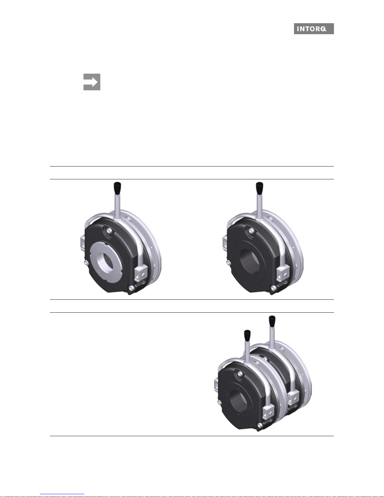
3.2 Layout
This chapter describes the variants, layout and functionality of the INTORQ BFK458 spring-applied brake.
The basic module E is adjustable (the braking torque can be reduced using the adjustment ring). The special
feature for basic module L (with an identical design) is the more dura ble materials (torque support, guide
pins, toothed intermediate ring, friction lining and gear teeth). The double-brake version is especially useful
in redundant braking applications.
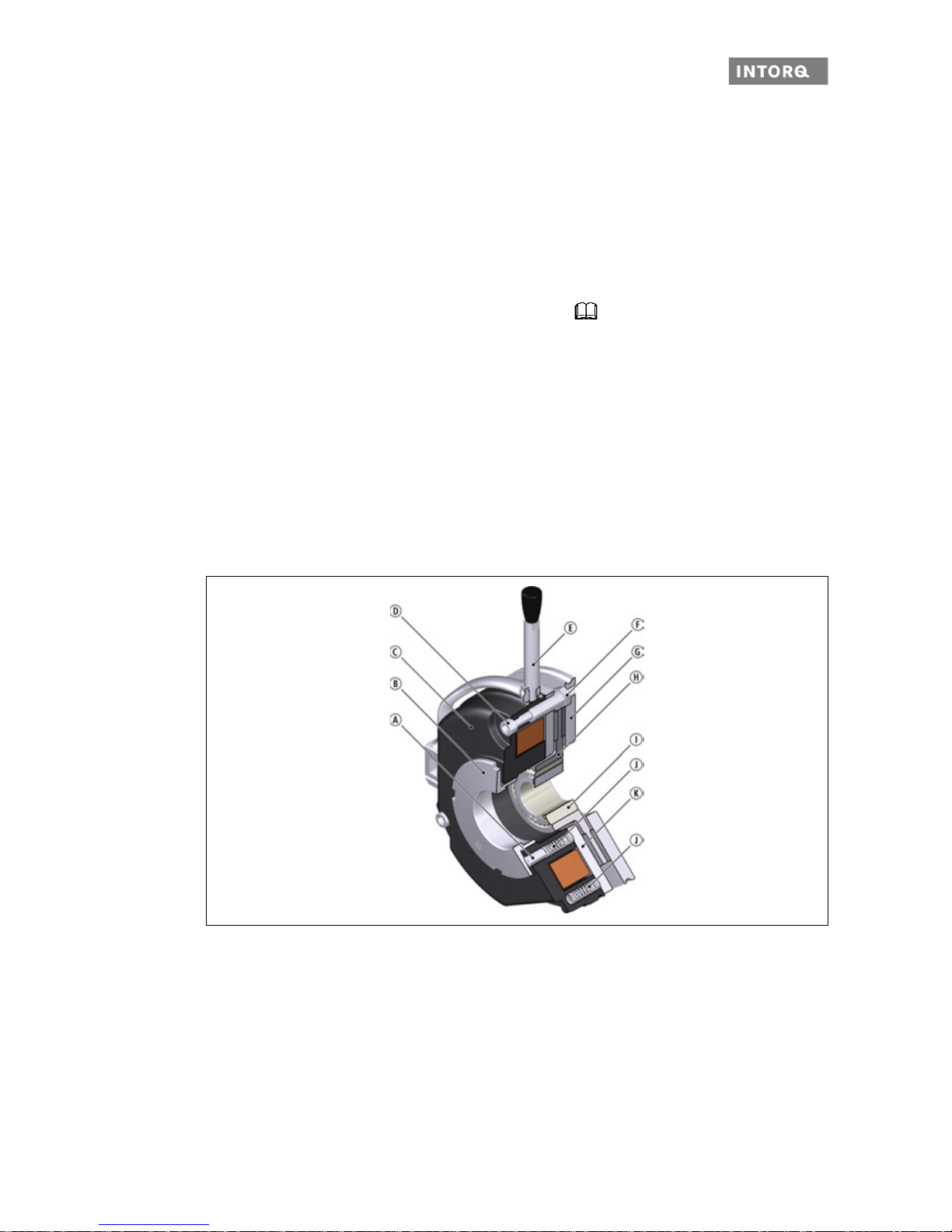
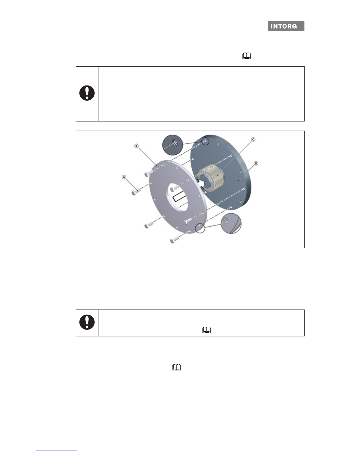
3.2.1 Basic module E
Fig. 1 Design of the INTORQ BFK458 spring-applied brake: Basic module E (complete stator) + rotor + hub + flange
Compression piece
Torque adjustment ring
Stator
Socket head cap screw
Manual release (optional)
Sleeve bolt
Flange
Rotor
Hub
Compression spring
Armature plate
Page 13
Product description
INTORQ | BA 14.0168 | 09/2015 13
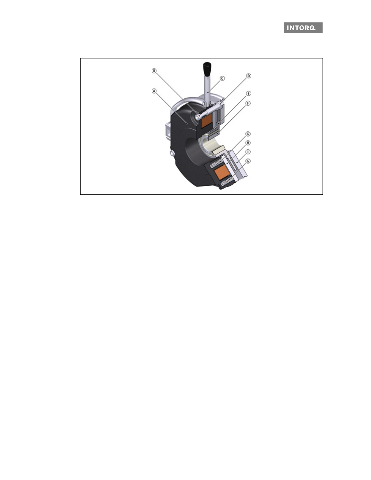
3.2.2 Basic module N
Fig. 2 Design of the INTORQ BFK458 spring-applied brake: Basic module N (complete stator) + rotor + hub + flange
3.2.3 Basic module L
Description of the LongLife design:
❚ Armature plate with low backlash and reinforced torque support
❚ Compression springs with guide pins for protection against shearing forces
❚ Aluminium rotor with toothed intermediate ring: Low-wear friction lining and low-wear gear teeth
The LongLife design can be configured modularly for sizes 6 to size 12 in combination with the specified rated torques. The specifications are as follows:
❚ The magnetic part corresponds to the design N.
❚ Rear holes and extensions are not possible.
❚ A microswitch in the size 12 is not configurable.
Stator
Socket head cap screw
Manual release (optional)
Sleeve bolt
Rotor
Hub
Compression spring
Armature plate
Flange
Page 14
Product description
INTORQ | BA 14.0168 | 09/2015 14
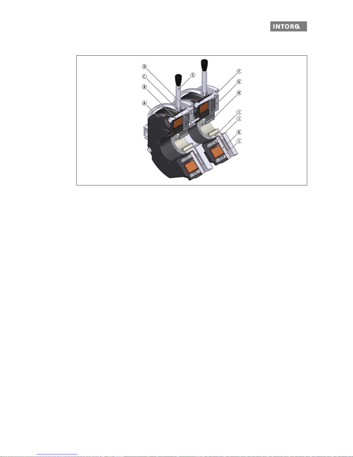
3.2.4 Basic module N, doubled design
Fig. 3 Design of the INTORQ BFK458 spring-applied brake: Basic module N, doubled design with intermediate flange
Function
The spring-applied brake is a single-disk brake wi th two friction surfaces. The braking torque is generated
by several pressure springs with friction locking. The braking circuits are released electromagnetically. During the braking procedure, the spring-applied brake converts kinetic energy into heat energy. Due to the static braking torque, loads can be held at standstill. Emergency braking is possib le at high speed of rotation.
Note that the wear will increase when there is emergency braking with high switching energy.
Braking and release
During the braking procedure, the inner and outer springs use the armature plate to press the rotor (which
can be shifted axially on the hub) against the frict io n surfa c e. T he asb est os-fre e f r ict ion lining s e nsure h igh
braking torque and low wear. The braking torque is transmitted between the hu b and the rotor via gear teeth.
When the brakes are applied, an air gap "s
L
" is present between the stator and the armature plate. To release
the brake, the coil of the stator is energised with the DC voltage provided. The resulting magnetic flux works
against the spring force to draw the armature plate to the stator. This releases the rotor from the spring force
and allows it to rotate freely.
Brake torque reduction
For the basic module E, the spring force and thus the brake torque can be reduced by un screwing the central
adjustment ring.
Stator
Socket head cap screw
Screw for intermediate flange
Intermediate flange
Manual release (optional)
Sleeve bolts
Flange
Hub
Rotor
Compression spring
Armature plate
Page 15

Product description
INTORQ | BA 14.0168 | 09/2015 15
3.3 Optional configuration
3.3.1 Manual release (optional)
To temporarily release the brake when there is no electricity available, a manual relea se function is available
as an option. The manual release can be retrofitted (for installation refer to 41).
3.3.2 Optional microswitch
The micro-switch is used for the release check or for wear monitoring. The user is responsib le for arrang ing
the electrical connection for this optional microswitch.
❚ Usage for the (air) release check: The motor will start only after the brake has been released. This ena-
bles the microswitch to monitor for errors (e.g. when the motor does not start because of a defective
rectifier, if there are broken connecting cables, defective coils, or an excessive air gap).
❚ Usage for monitoring wear: The brake and motor are supplied with no power when the air ga p is too
large.
3.3.3 Optional encapsulated design
This design not only prevents the penetration of spray water and dust, but also the spreading of abrasion
particles outside the brake. This is achieved by the following encapsul ation:
❚ A cover ring over the armature plate and rotor.
❚ Cover plate
❚ Shaft seal (can be supplied for continuous shaft).
3.3.4 Optional CCV
The Cold Climate Version (CCV) allows the brake to be operated at lower ambient temperatures.
Page 16
Technical specifications
INTORQ | BA 14.0168 | 09/2015 16
4 Technical specifications
Usage conditions for the INTORQ spring-applied brake
❚ Degree of protection:
- The brake is designed for operation under the environmental conditions that apply to IP54 protection. Because of the numerous possibilities of using the brake, it is still necessary to check the f unctionality of all mechanical components under the corresponding operating conditions.
❚ Ambient temperature:
- -20 °C to +40 °C (standard)
- -40 °C to +40 °C (Cold Climate Version: CCV)
4.1 Brake torque reduction
For basic module E, the brake torque can be reduced using the adjustment ring in the stator. The adjustment
ring can be unscrewed to the maximum protrusion of "h
Emax.
" ( 17 and 56).
NOTICE
Please observe that engagement times and disengagement times change de pending on the
brake torque.
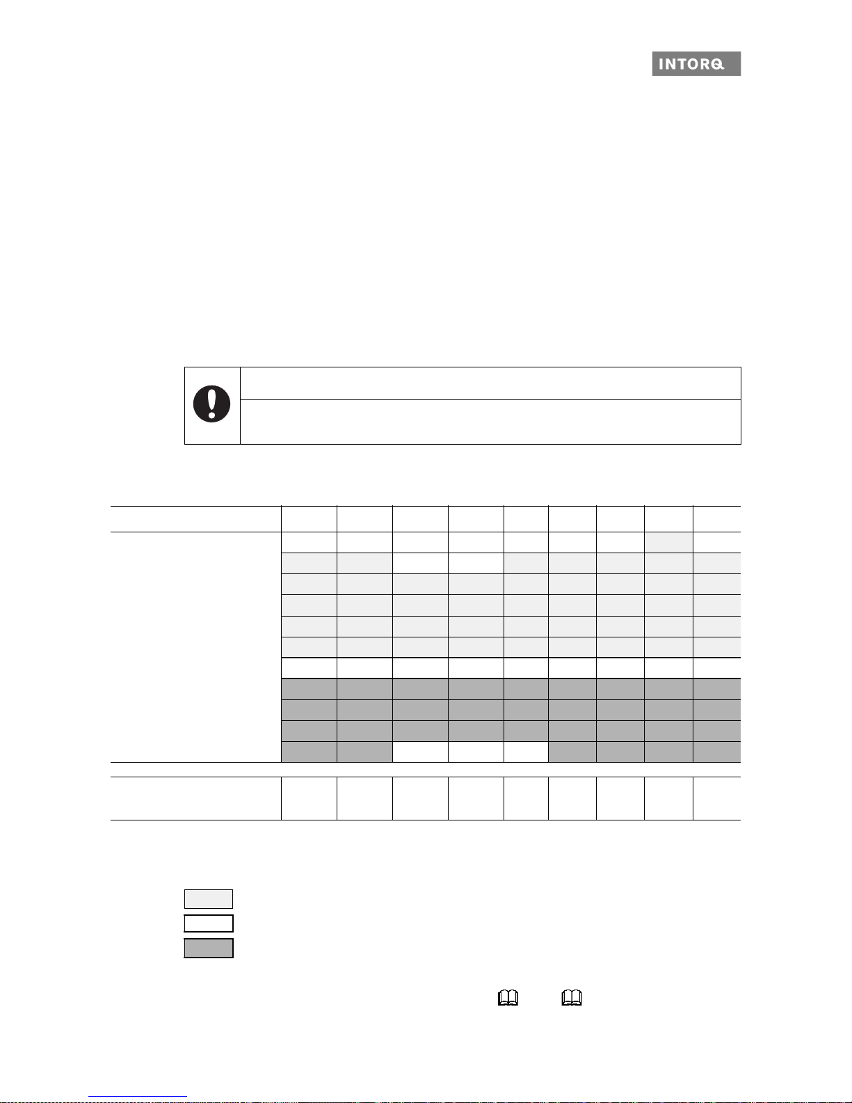
Size 06 08 10 12 14 16 18 20 25
Rated torque MK [Nm] of the
brake, rated value at a relative
speed of rotation of 100 rpm
80 E
1.5 E 3.5 N/E 25 N/E 35 N/E 65 N/E 115 N/E 175 N/E
2 N/E 4 E 7 N /E 14 N/E 35 N 45 N/E 80 N/E 145 N/E 220 N
2.5 N/E 5 N/E 9 N/E 18 N/E 40 N/E 55 N/E 100 N/E 170 N/E 265 N/E
3 N/E 6 N/E 11 N/E 23 N/E 45 N/E 60 N/E 115 N/E 200 N/E 300 N/E
3.5 N/E 7N/E 14 N/E 27 N/E 55 N/E 70 N/E 130 N/E 230 N/E 350 N/E
4 N/E 8 N/E 16 N/E 32 N/E 60 N/E 80 N/E 150 N/E 260 N/E 400 N/E
4,5 N/E 9N/E 18 N/E 36 N/E 65 N/E 90 N/E 165 N/E 290 N/E 445 N/E
5 E 10 E 20 E 40 E 75 N/E 100 N/E 185 N/E 315 N/E 490 N/E
5.5 E 11 E 23 N/E 46 N/E 80 N/E 105 N/E 200 N/E 345 N/E 530 N/E
6 N/E 12 N/E 125 N/E 235 N/E 400 N/E 600 N/E
Torque reduction per latch-in
position [Nm] for type E
0.2 0.35 0.8 1.3 1.7 1.6 3.6 5.6 6.2
Tab. 1: N Braking torque for the N design (without adjustment ring)
E Braking torque for the E design (with adjustment ring)
L LongLife design
Operating brake (s
Lmax
approx. 2.5 x sLN)
Standard braking torque
Holding brake with emergency stop (s
Lmax.
approx. 1.5 x sLN)
Page 17
Technical specifications
INTORQ | BA 14.0168 | 09/2015 17
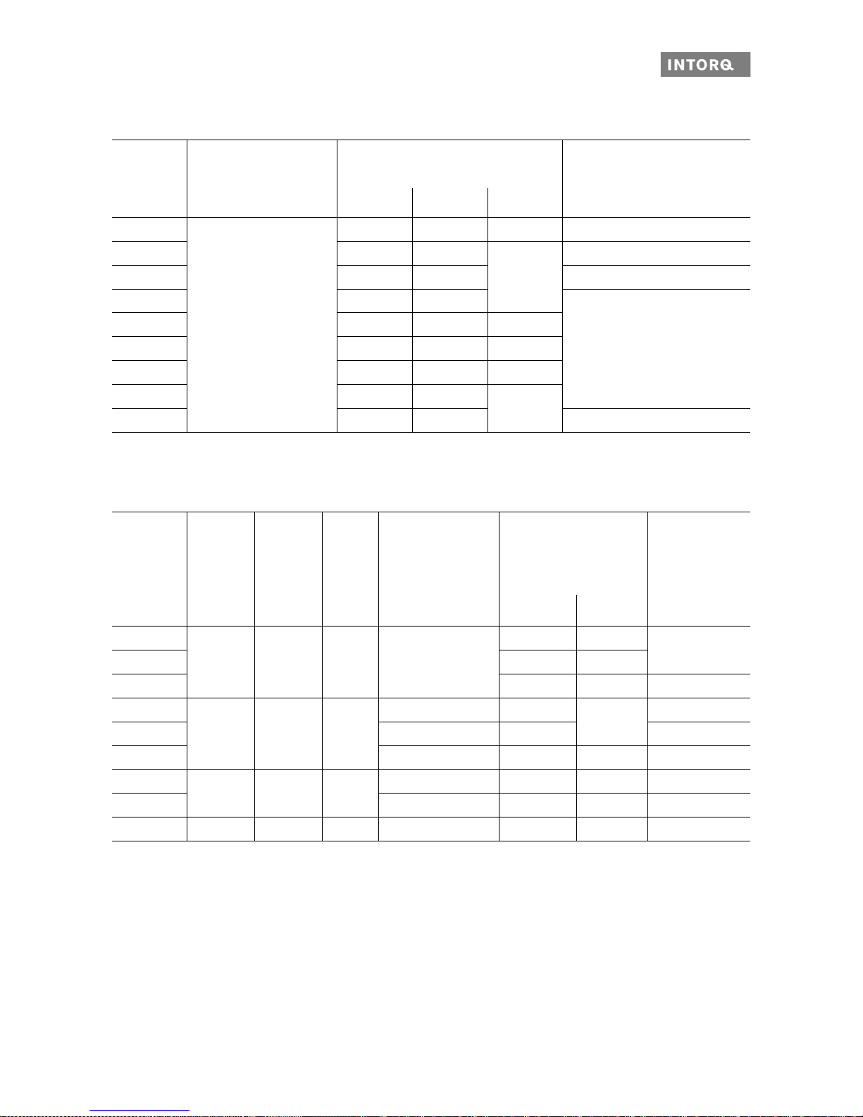
4.2 Rated data
Tab. 3: Rated data for air gap specifications
1)
The friction lining is designed so that the brake can be adjusted at least 5 times.
Size
Rated brake torque at
n=100 rpm
Braking torque at n
0
[rpm] [%]
Max. rotation speed n
0max
for
horizontal mounting position
[%] 1500 3000 maximum [rpm]
06
100
87 80 74 6000
08 85 78
73
5000
10 83 76 4000
12 81 74
3600
14 80 73 72
16 79 72 70
18 77 70 68
20 75 68
66
25 73 66 3000
Tab. 2: Rated data for braking torques, depending on the speed and permissible limiting speeds
Size s
LN
+0.1 mm
-0.05 mm
s
Lmax.
operating
brake
s
Lmax.
holding
brake
Max. adjustment,
permissible
wear path
Rotor thickness Protrusion
torque
adjustment ring
h
Emax.
[mm] [mm] [mm] [mm] min.1) [mm] max. [mm] [mm]
06
0.2 0.5 0.3 1.5
4.5 6.0
4.5
08 5.5 7.0
10 7.5 9.0 7.5
12
0.3 0.75 0.45
2.0 8.0
10.0
9.5
14 2.5 7.5 11
16 3.5 8.0 11.5 10
18
0.4 1.0 0.6
3.0 10.0 13.0 15
20 4.0 12.0 16.0 17
25 0.5 1.25 0.75 4.5 15.5 20.0 19.5
Page 18

Technical specifications
INTORQ | BA 14.0168 | 09/2015 18
1)
The screw length depends on the material and the thickness of the customer's mounting place.
2)
The thread in the threading surface is offset by 30° in reference to the centre axle of the manual release
lever.
3)
Hex head screw according to DIN EN ISO 4017 - 8.8.
Size Pitch circle Screws
for the flange mount
DIN EN ISO 4762 (8.8)
Minimum depth
of the clearing holes
(in end shield)
Tightening torque
±5%
[mm]
1)
[mm]
Screws
[NM]
Complete lever
[NM]
06 72 3 x M4 0.5 3.0
2.8
08 90 3 x M5 1 5.9
10 112 3 x M6 2
10.1 4.8
12 132 3 x M6 3
14 145
3 x M8
1.5
24.6
12
16 170 0.5
18
196
4 x M8
2)
0.8
23
20 230
4 x M10
2)
2.1
48
25
278
6 x M10
3)
5
40
Tab. 4: Rated data for the screw set for flange mounting
Size
Pitch circle
[mm]
Screw set for
mounting to the
flange
Minimum depth
of the clearing
hole
[mm]
Screw set for
mounting onto the
motor/friction plate
Screw set for
flange with
through hole
06 72 3 x M4x35 0.5 3 x M4x40 3 x M4x45
08 90 3 x M4x40 1 3 x M5x45 3 x M5x50
10 112 3 x M6x50 2 3 x M6x55 3 x M6x65
12 132 3 x M6x55 3 3 x M6x60 3 x M6x70
14 145 3 x M6x60 1.5 3 x M8x70 3 x M8x80
16 170 3 x M8x70 0.5 3 x M8x80 3 x M8x90
18 196 6 x M8x80 0.8 6 x M8x90 20 230 6 x M10x90 2.1 6 x M10x100 25 278 6 x M10x100 5 6 x M10x110 -
Tab. 5: Rated data for the screw set for brake mounting
Page 19

Technical specifications
INTORQ | BA 14.0168 | 09/2015 19
Size Pitch circle Screw set for mounting
double flange on stator, complete
DIN EN ISO 4762
strength grade 8.8 (10.9)
Thread depth in
the magnet
housing
Tightening
torque
±5%
[mm] Thread (4 pieces) [mm] [NM]
06 37.7 4 x M4 M4x16 10 3.0
08 49
4 x M5
M5x16
12
5.910 54
12 64 M5x20
14 75
4 x M6
M6x20
10.1
16 85 M6x25 15
18 95 4 x M8 M8x25 17 24.6
20 110
4 x M10
M10x25
20
48
25 140 M10x30 - 10.9 71
Tab. 6: Rated data for the screw set, intermediate flange installation for double brake
Size Electrical power
P
20
1)
[W]
Coil voltage
U
[V]
Coil resistance
R
20
±8 %
[]
Rated current
I
N
[A]
06 20
24 28.8 0.83
96 460.8 0.21
103 530.5 0.194
170 1445 0.114
180 1620 0.111
190 1805 0.105
205 2101 0.098
08 25
24 23 1.04
96 368 0.26
103 424.4 0.242
170 1156 0.147
180 1296 0.138
190 1444 0.131
205 1681 0.121
Tab. 7: Rated data for coil power
Page 20

Technical specifications
INTORQ | BA 14.0168 | 09/2015 20
10
30 24 19.2 1.25
31 96 297.3 0.322
32 103 331.5 0.31
30 170 963.3 0.176
32 180 1013 0.177
30 190 1203 0.157
33 205 1273 0.160
12 40
24 14.4 1.66
96 230.4 0.41
103 265.2 0.388
170 722.5 0.235
180 810 0.222
190 902.5 0.210
205 1051 0.195
14
50
24 11.5 2.08
96 184.3 0.52
53 103 200.2 0.514
50 170 578 0.294
53 180 611.3 0.294
50 190 722 0.263
53 205 792.9 0.258
16
55
24 10.5 2.29
96 167.6 0.573
56 103 189.5 0.543
55
170 525.5 0.323
180 589.1 0.305
60 190 601.7 0.315
56 205 750.5 0.292
Size Electrical power
P
20
1)
[W]
Coil voltage
U
[V]
Coil resistance
R
20
±8 %
[]
Rated current
I
N
[A]
Tab. 7: Rated data for coil power
Page 21

Technical specifications
INTORQ | BA 14.0168 | 09/2015 21
1)
Coil power at 20 °C
18 85
24 6.8 3.54
96 108.4 0.885
103 124.8 0.825
170 340 0.5
180 387.2 0.472
190 424.7 0.447
205 494.4 0.414
20 100
24 5.76 4.16
96 92.2 1.04
103 106.1 0.970
170 289 0.588
180 324 0.55
190 328.2 0.578
205 420.3 0.487
25 110
24 5.24 4.58
96 83.8 1.14
103 96.5 1.06
170 262.7 0.647
180 294.6 0.611
190 328.2 0.578
205 382.1 0.536
Size Electrical power
P
20
1)
[W]
Coil voltage
U
[V]
Coil resistance
R
20
±8 %
[]
Rated current
I
N
[A]
Tab. 7: Rated data for coil power
Page 22

Technical specifications
INTORQ | BA 14.0168 | 09/2015 22
4.3 Switching times
The switching times listed here are guide values which apply to DC switching with rated air gap s
LN
, warm
coil and standard characteristic torque. The switching times given are mean values and subject to variations.
The engagement time t
1
is approximately 8 to 10 times longer for AC switching.
Fig. 4 Operating/switching times of the spring-applied brakes
1)
The maximum permissible friction energy QE relates to the standard friction lining.
2)
These switching times are specified for the usag e of INTORQ bridge/half-wave rect ifiers and coils with a
supply voltage of 205 V DC at s
LN
and 0.7 IN.
t1Engagement time t11Reaction delay of engagement
t
2
Disengagement time (up to M = 0.1 MK)t
12
Rise time of the braking torque
M
K
Rated torque U Voltage
Size Rated torque
M
K
[Nm]
Q
E
[J]
1)
S
hue
[1/h]
Switching times [ms]
2)
DC engagement Disengage
t
11
t
12
t
1
t
2
06 4 30007915132845
08 8 75005015163157
10 16 12000 40 28 19 47 76
12 32 24000 30 28 25 53 115
14 60 30000 28 17 25 42 210
16 80 36000 27 27 30 57 220
18 150 60000 20 33 45 78 270
20 260 80000 19 65 100 165 340
25 400 120000 15 110 120 230 390
Tab. 8: Switching energy - switching frequency - switching times
Page 23
Technical specifications
INTORQ | BA 14.0168 | 09/2015 23
Engagement time
The transition from a brake-torque-free state to a holding-braking torque is no t free of time lags.
For emergency braking, short engagement times for the brake are absolutely essential. The DC switching in
connection with a suitable spark suppressor must therefore be provided.
Engagement time for DC-side switching: A braking torque reduction via the torque adjustment ring prolongs
the engagement time and reduces the d iseng ageme nt time. An a nti-magne tic plate is availab le when there
is excessive prolongation. This plate is installed between the stator and the armatu re plate. The plate redu ces the engagement time and prolongs the disengagement time.
Engagement time for AC-side switching: The engagement time is sign ificantly prolonged (approx. 10 times
longer).
❚ If the drive system is operated with a frequency inverter so that the brake will not be de-energised befo re
the motor is at standstill, AC switching is also possible (not applicable to emergency braking).
❚ The specified engagement times are valid for DC switching with a spark suppressor.
- Circuit proposals: ( 46).
Disengagement time
The disengagement time is the same for DC and AC switching. The specified disengagement times always
refer to control using INTORQ rectifiers and rated voltage.
NOTICE
Connect the spark suppressors in parallel to the contact. If this is not admissible for safety
reasons (e.g. with hoists and lifts), the spark suppressor can also be connected in parallel to
the brake coil.
NOTICE
Spark suppressors are available for the rated voltages.
Page 24
Technical specifications
INTORQ | BA 14.0168 | 09/2015 24
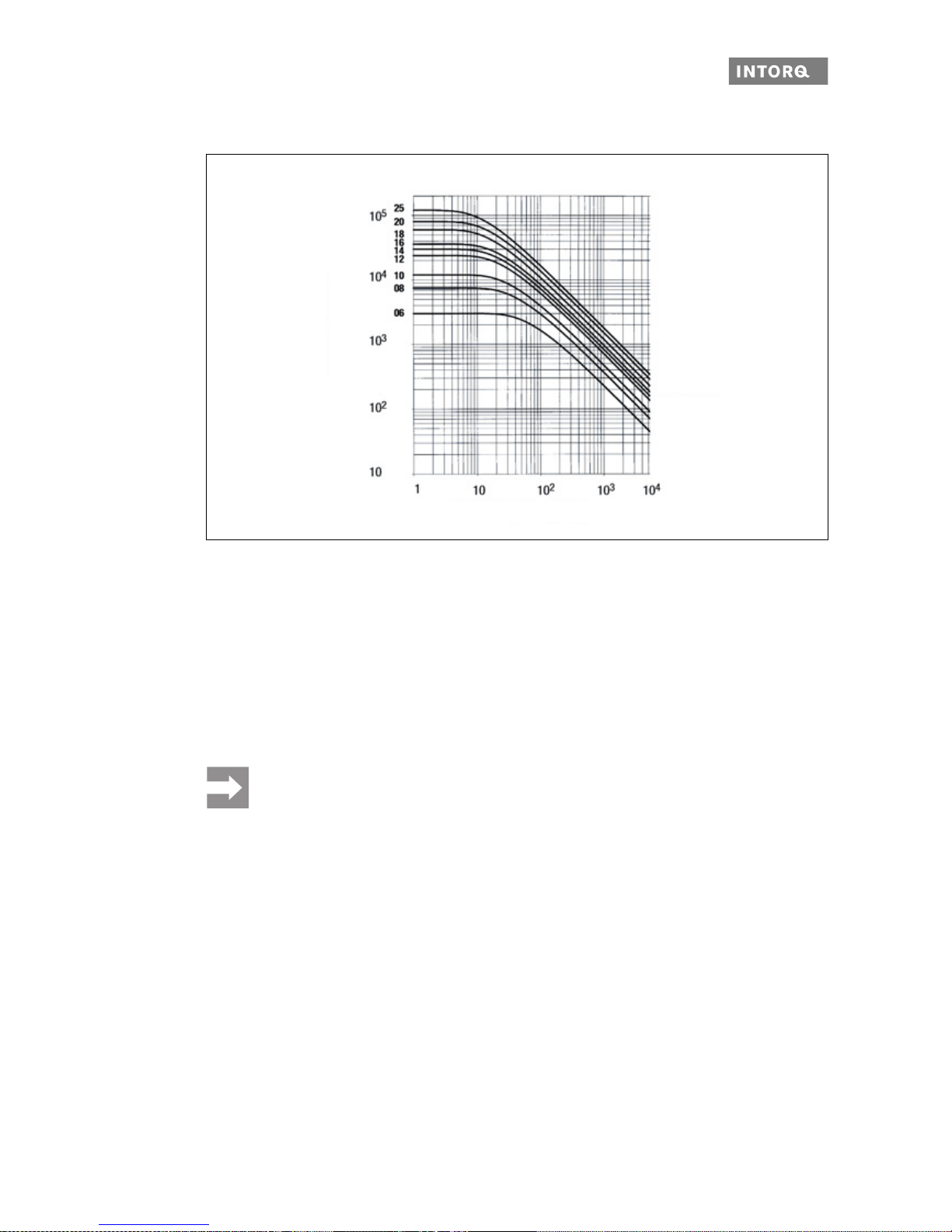
4.4 Switching energy / switching frequency
Fig. 5 Switching energy as a function of the switching frequency
The permissible switching frequency S
hmax
depends on the amount of heat QR (refer to Figure 5). At a pre-
set switching frequency S
h
, the permissible amount of heat is Q
Smax
.
NOTICE
With high speeds of rotation and switching energy, the wear increases strongly, becau s e very
high temperatures occur at the friction surfaces for a short time.
Sizes
Switching frequency Sh [h-1]
Switching energy Q [J]
S
hmax
S
hue
–
ln 1
Q
R
Q
E
---------
–
--------------------------------=
Q
smaxQE
1e
S
hue
–
S
h
-------------------
–
=
Page 25

Technical specifications
INTORQ | BA 14.0168 | 09/2015 25
4.5 Electromagnetic compatibility
4.6 Emissions
Heat
Since the brake converts kinetic energy as well as mechanical and electrical energy into heat, the surface
temperature varies considerably, depending on the operating conditions and possible heat dissipation. Under unfavourable conditions, the surface temperature can reach 130 °C.
Noise
The loudness of the switching noise during engaging and disengaging depends on the air gap "s
L
" and the
brake size.
Depending on the natural oscillation after installation, operating conditions and the state of the friction sur-
faces, the brake may squeak during braking.
NOTICE
The user must ensure compliance with EMC Directive 2004/108/EC usin g ap propriate co ntrols
and switching devices.
NOTICE
If an INTORQ rectifier is used for the DC switching of the spring-applied brake: If the switching frequency exceeds five switching operations per minute, the use of a mains filter is
required.
If the spring-applied brake uses a rectifier from another manufacturer for the switching, it may
become necessary to connect a spark suppressor in parallel with the AC voltage. Spark suppressors are available on request, depending on the co il voltage.
Page 26
Technical specifications
INTORQ | BA 14.0168 | 09/2015 26
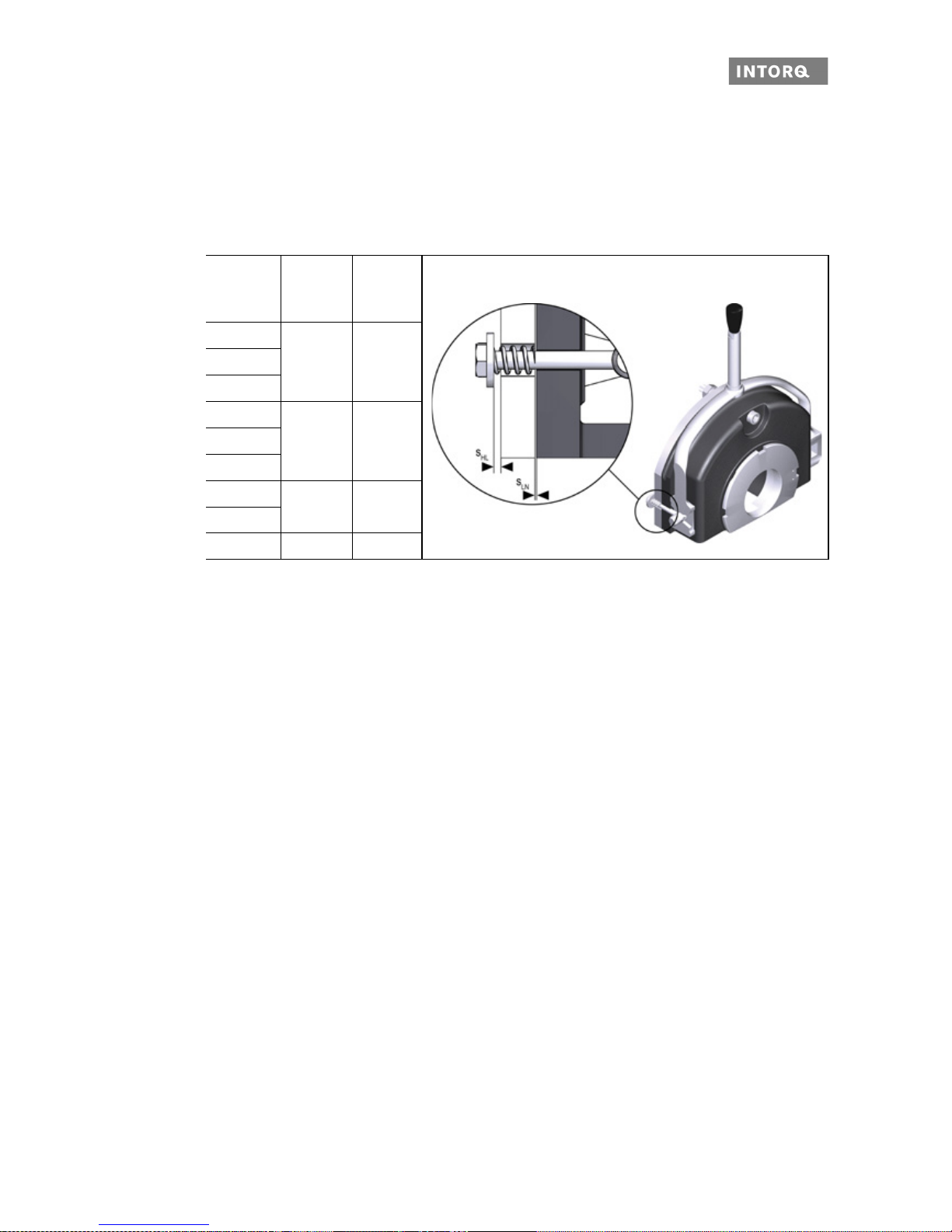
4.7 Manual release
The manual release mechanism is used to release the brake by hand and can be retrofitted.
The manual release springs back to its base position automatically after operation. The manual release re-
quires an additional air gap "s
HL
" in order to function; this is factory-set prior to delivery. Check for the dimen-
sion "s
HL
" after the installation.
Size
s
LN
+0.1
-0.05
s
HL
+0.1
(mm) (mm)
06
0.2 108
10
12
0.3 1.514
16
18
0.4 2
20
25 0.5 2.5
Tab. 9: Adjustment setting for manual release
Page 27

Technical specifications
INTORQ | BA 14.0168 | 09/2015 27
4.8 Labels on product
There is a packaging label on the package. The nameplate is glued to the ou ter surface of the brake.
Fig. 6 Packaging label (example)
INTORQ Manufacturer
Bar code
BFK458-12E Type (see product key)
FEDERKRAFTBRREMSE (SPRING-APPLIED BRAKE) Designation of the product family
Nr. (No.) 15049627 Type number
24 V DC Rated voltage
32 NM Rated torque
1 St. (1 piece) Quantity per box
CSA_CUS approval
40W Rated power
20 H7 Hub diameter
02.06.15 Packaging date
Rostschutzverpackung-Reibfläche fettfrei halten!
(Anti-rust packaging: keep friction surface free of grease!)
Addition
CE mark
Page 28

Technical specifications
INTORQ | BA 14.0168 | 09/2015 28
Fig. 7 Nameplate (example)
INTORQ Manufacturer
CSA_CUS approval
t=40°C Ambient temperature
BFK458-25E Type (see product key)
Class F Insulation class
180 V DC Rated voltage
110 W Rated power
Nr. (No.) 15049627 Type number
350 NM Rated torque
30/07/2015 Date of manufacture
CE mark
Page 29
Mechanical installation
INTORQ | BA 14.0168 | 09/2015 29
5 Mechanical installation
This chapter provides step-by-step instructions for the installation.
Important notes
Design of end shield and shaft
❚ Comply with the specified minimum requirements regarding the end shield and the motor shaft to ensure
a correct function of the brake.
❚ The diameter of the shaft shoulder must not be greater than the tooth-base diameter of the hub.
❚ The form and position tolerances apply only to the materials mentioned. Con s ult with INTORQ before
using other materials; INTORQ's written confirmation is required for such usage.
❚ The brake flange must be supported by the end shield across the full surface.
Minimum requirements of the end shield
1)
Consult with INTORQ before using other materials.
The diameter of the shaft shoulder must not be greater than the tooth-base diameter of the hub.
NOTICE
The toothed hub and screws must not be lubricated with grease or oil.
Size Axial run-out
[mm]
Material
1)
Evenness
[mm]
Roughness Tensile
strength
R
m
[N/mm2]
Miscellaneous
06 0.03
S235JR; C15;
EN-GJL-250
< 0.06 Rz6
250
❚ Threaded holes
with minimum
thread depth
18
❚ Free of grease
and oil
08 0.03
10 0.03
12 0.05
14 0.05
< 0.10 RZ10
16 0.08
18 0.08
20 0.08
25 0.10
Tab. 10: End shield as counter friction surface
Page 30
Mechanical installation
INTORQ | BA 14.0168 | 09/2015 30
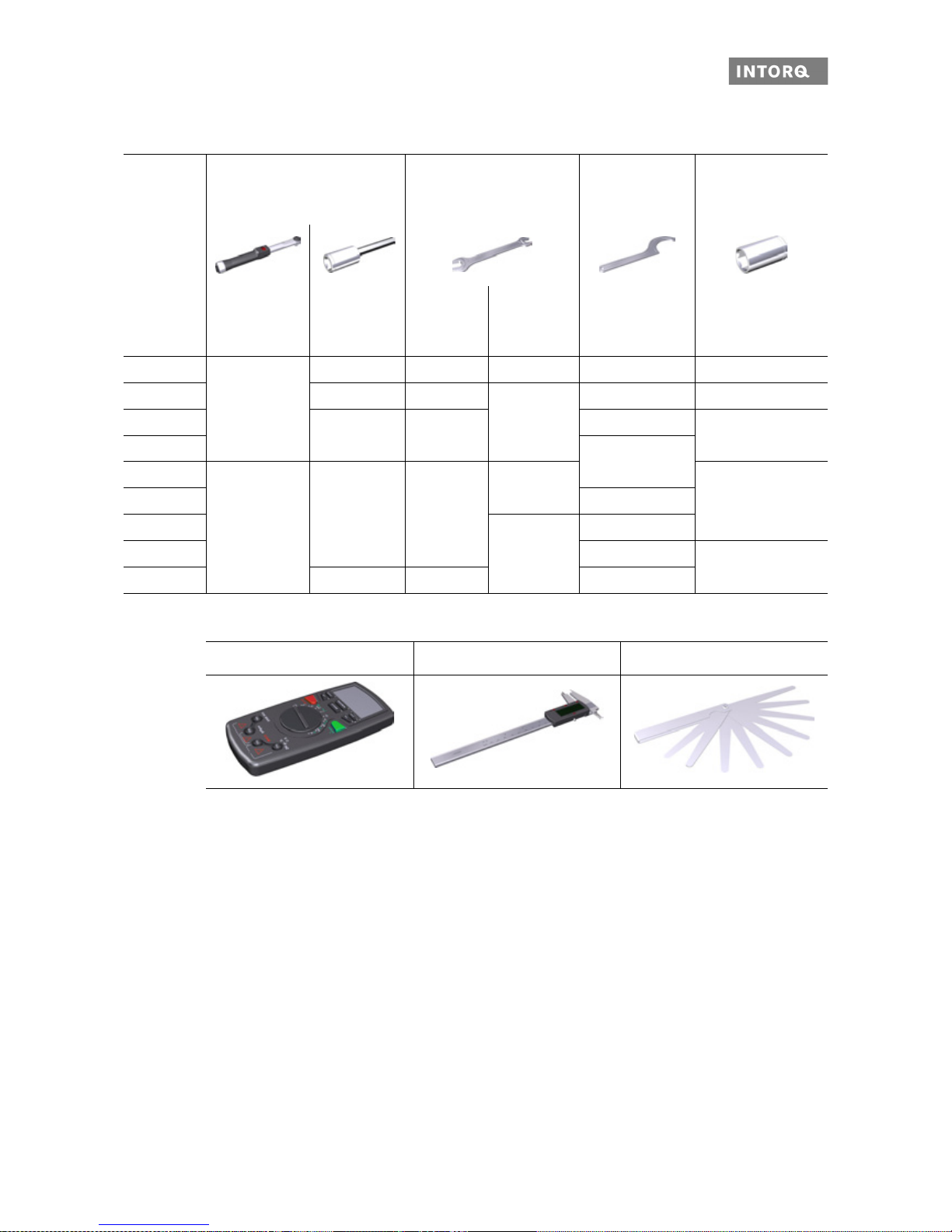
5.1 Tools
5.2 Preparing the installation
1. Remove the packaging from the spring-applied brake and dispose of it properly.
2. Check the delivery for completeness.
3. Check the nameplate specifications (especially rated voltage)!
Size Torque key
Insert for hexagonal socket
(Allen) screws
Wrench size of
open-jawed spanner
[mm]
Spanner wrench
DIN 1810
design A
Socket spanner for
flange mounting,
outer
Measurement
range
[NM]
Wrench width
[mm]
Sleeve
bolts
Manual
release
screws
Diameter
[mm]
Width across flats
[mm]
06
1 to 12
3 8 7 / 5.5 45 - 55 7
08 4 9
10 / 7
52 - 55 8
10
512
68 - 75
10
12
80 - 90
14
20 to 100
615
12 / 8
1316 95 - 100
18
- / 10
11 0 - 115
20 135 - 145
17
25 8 17 155 - 165
Multi-meter Calliper gauge Feeler gauge
Page 31
Mechanical installation
INTORQ | BA 14.0168 | 09/2015 31
5.3 Installing the hub onto the shaft
Fig. 8 Installing the hub onto the shaft
1. Press the hub with a moderate amount of force to the shaft.
2. Secure the hub against axial displacement (for example, by using a circlip).
NOTICE
The customer is responsible for constructing the shaft-hub connection. Make sure that the
bearing length of the key is identical to the length of the hub.
NOTICE
Check the tensile strength of the hub material: When operating with high torque, consult with
INTORQ and use a steel hub with a higher tensile strength.
Circlip
Hub
Keyway
End shield
NOTICE
If you are using the spring-applied brake for reverse operations, glue the hub to the shaft.
Page 32

Mechanical installation
INTORQ | BA 14.0168 | 09/2015 32
5.4 Installing the brake
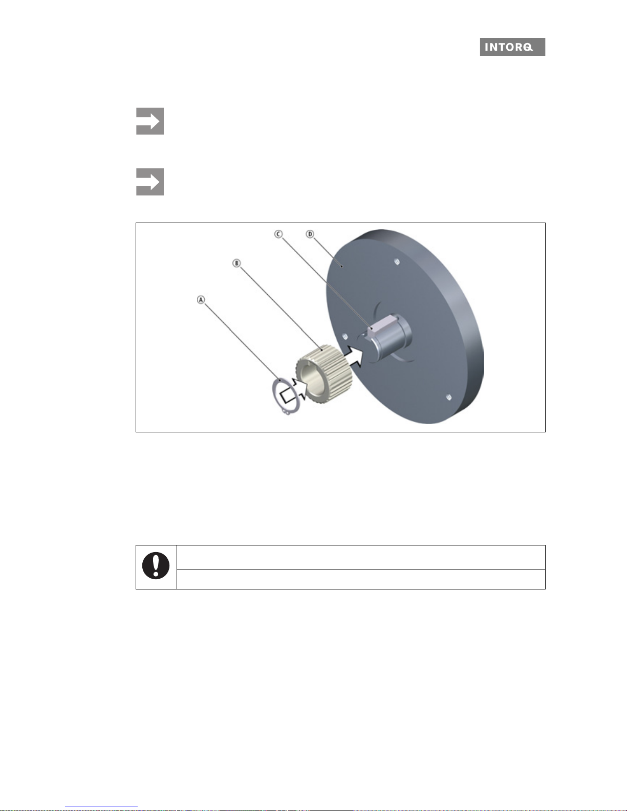
Installing the rotor (without friction plate)
Fig. 9 Assembly of the rotor
1. Push the rotor on the hub.
2. Check if the rotor can be moved manually.
Fig. 10 Mounting the complete stator
3. Screw the complete stator to the end shield Use the supplied set of screws and a torque wrench.
Rotor
Hub
End shield
Socket head cap screw
Stator, complete
Terminal clip
Rotor
End shield
Page 33

Mechanical installation
INTORQ | BA 14.0168 | 09/2015 33
4. Remove the terminal clips and dispose of properly.
Fig. 11 Tightening the screws with a torque wrench
5. Check the air gap near the screws using a feeler gauge. These values These values must match the
specifications for "s
LN
" in the table ( 17).
Fig. 12 Adjusting the air gap
6. If the measured value "sL" is outside of the tolerance "sLN", readjust this dimension. Loosen the socket
head cap screws slightly and adjust the air gap (turn the sleeve bolts using a wrench).
7. Use a torque wrench to tighten the socket head cap screws (refer to Figure 11).
NOTICE
Do not push on the feeler gauge more than 10 mm between the armature plate and the stator!
Page 34

Mechanical installation
INTORQ | BA 14.0168 | 09/2015 34
5.5 Installing the friction plate (optional)
Fig. 13 Mounting the friction plate
1. Place the friction plate against the end shield. The lip edging of the friction plate must remain visible!
2. Align the pitch circle and the thread along the bore holes.
5.6 Mounting the flange
5.6.1 Mounting the flange without additional screws
1. Place the flange against the end shield.
2. Check the pitch circle and the threads of the bore holes.
3. Use the proper screw set ( 32 and 62) to mount the brake.
Stator
Rotor
Friction plate
End shield
NOTICE
When dimensioning the thread depth in the end shield, be sure to take into account the permissible wear ( 18).
Page 35

Mechanical installation
INTORQ | BA 14.0168 | 09/2015 35
5.6.2 Installing the flange (variants: size 06)
The flange can be screwed to the end shield on the outer pitch circle (screw dimensioning is specified in
18).
Fig. 14 Flange mounting for sizes 06 - 16
1. Make sure that there are clearing holes in the end shield (refer to the table) at the positions of the screws
in the stator.
2. Place the flange against the end shield.
3. Use the three screws to screw the flange to the end shield.
4. Check the height of the screw heads. The screw heads must not be higher than the minimum rotor thickness. Use screws according to the table 18.
NOTICE
Clearing holes for the screws in the end shield must be behind the threaded screw holes in
the flange. Without the clearing holes, the minimal rotor thickness cannot be used. The
screws must not press against the end shield.
Screw from the screw set
Flange
Hub
End shield
NOTICE
Tighten the screws evenly (tightening torques 18).
NOTICE
When mounting the flange, the various size classes must be distinguished:
sizes 06 - 16, 18 - 20 and 25 are mounted differently.
Page 36

Mechanical installation
INTORQ | BA 14.0168 | 09/2015 36
5.6.3 Installing the flange (variants: sizes 18 - 20)
The flange can be screwed to the end shield on the outer pitch circle (refer to Tab. 4).
Fig. 15 Flange mounting for sizes 18 - 20
1. Place the flange against the end shield.
2. Check the pitch circle and the threads of the bore holes .
3. Use the four screws to screw the flange to the end shield.
4. Check the height of the screw heads. The screw heads must not be higher than the minimum rotor thickness. Use screws according to the table 18.
NOTICE
❚ Clearing holes for the screws in the end shield must be behind the t hreaded screw holes in
the flange. Without the clearing holes, the minimal rotor thickness cannot be used. The
screws must not press against the end shield.
❚ For sizes 18 and 20, the fastening surface threading must be angled at 30° to the centre
axis to the manual release lever.
Screw from the screw set
Flange
Hub
End shield
NOTICE
Tighten the screws evenly (tightening torques: 18).
Page 37
Mechanical installation
INTORQ | BA 14.0168 | 09/2015 37
5.6.4 Installing the flange (variants: size 25)
The flange can be screwed to the end shield on the outer pitch circle (refer to Tab. 4).
Fig. 16 Flange mounting for size 25
1. Place the flange against the end shield.
2. Check the pitch circle and the threads of the bore holes .
3. Use the six screws to screw the flange to the end shield.
4. Check the height of the screw heads. The screw heads must not be higher than the minimum rotor thickness. Use screws according to the table 18.
NOTICE
❚ Clearing holes for the screws in the end shield must be behind the t hreaded screw holes in
the flange (refer to Chapter 3.2). Without the clearing holes, the minimal rotor thickness
cannot be used. The screws must not press against the end shield.
❚ For size 25, the fast ening surface thre ading must be angle d at 30° to the centre axis to the
manual release lever.
Hex screw
Flange
Hub
End shield
NOTICE
Tighten the screws evenly (tightening torques: 18).
Page 38

Mechanical installation
INTORQ | BA 14.0168 | 09/2015 38
5.7 Installing the double-rotor brake
Fig. 17 Installing the intermediate flange
Required: The front hub has to be mounted on the shaft!
1. Mount the intermediate flange with the four screws in the threads of the rear magnet housing.
All other steps for mounting the front brake are carried out as described in Chapter 5.4.
Screw from the screw set
Intermediate flange
Rear stator
Front hub
NOTICE
When installing the double brake, use screws with the required strength grade. Screw them in
with the proper torque as specified in Tab.6, 19).
Page 39

Mechanical installation
INTORQ | BA 14.0168 | 09/2015 39
5.8 Cover ring assembly
Fig. 18 Cover ring assembly
1. Pull the cables through the cover ring.
2. Slide the cover ring over the stator.
3. Press the correspon ding lips of the co ver ring in the groove of the stator an d in the gro ove of the flange.
If a friction plate is used, the lip must be pulled over the edging.
Cover ring
Socket head cap screw
Stator
Armature plate
Sleeve bolt
Flange
End shield
Friction plate
Page 40

Mechanical installation
INTORQ | BA 14.0168 | 09/2015 40
5.9 Installing the shaft seal
Fig. 19 Installing the shaft seal
NOTICE
When using a shaft seal, the brake has to be mounted so that it is centred properly!
The shaft diameter must be implemented in accordance with ISO tolerance h11, with a radial
eccentricity tolerance according to IT8 and an averaged su rface ro ug hn ess o f R
z
3.2 µm in
the sealing area.
Socket head cap screw
Shaft sealing ring
Stator, complete
Terminal Clip
Rotor
End shield
NOTICE
Please note the following for the version "brake with shaft sealing ring in torque adjustment ring":
❚ Lightly lubricate the lip of the shaft seal with grease.
❚ No grease should be allowed to contact the friction surfaces.
❚ When assembling the stator, push the shaft sealing ring carefully over the shaft. The shaft
should be located concentrically to the shaft seal.
Page 41

Mechanical installation
INTORQ | BA 14.0168 | 09/2015 41
5.10 Installing the manual release (retrofitting)
Fig. 20 Assembly of the manual release BFK458
1. Insert the bolt into the bore holes of the yoke.
2. Insert the pressure springs in the holes of the armature plate.
3. Push the hex head screw through the pressure spring in the armature plate and through the bore hole
in the stator.
4. Screw the hex head screws into the yoke bolts.
5. Tighten the hex head screws to fasten the armature plate against the stator.
6. Remove the terminal clips and dispose of properly.
7. Set the gap "s
LN
+ sHL" evenly using the hex head screws and the feeler gauge. Refer to Tab .11 for the
values for the dimension "s
LN
+ sHL".
Trunnion
Yoke
Lever
Stator
Terminal clip
Armature plate
Compression spring
Washer
Hexagon head screw
Size
s
LN
+0.1
-0.05
s
HL
+0.1
(mm) (mm)
06
0.2 108
10
12
0.3 1.514
16
18
0.4 2
20
25 0.5 2.5
Tab. 11: Adjustment setting for manual release
Page 42

Electrical installation
INTORQ | BA 14.0168 | 09/2015 42
6 Electrical installation
Important notes
6.1 Electrical connection
Circuit suggestions
DANGER
There is a risk of injury by electrical shock!
❚ The electrical connections may only be made by trained electricians!
❚ Make sure that you switch off the elec tricity before working o n the connection s! There is a
risk of unintended start-ups or electric shock.
NOTICE
❚ Make sure that the supply voltage matches the voltage specification on the nameplate.
NOTICE
The terminal pin sequence shown here does not match the actual order.
Page 43
Electrical installation
INTORQ | BA 14.0168 | 09/2015 43
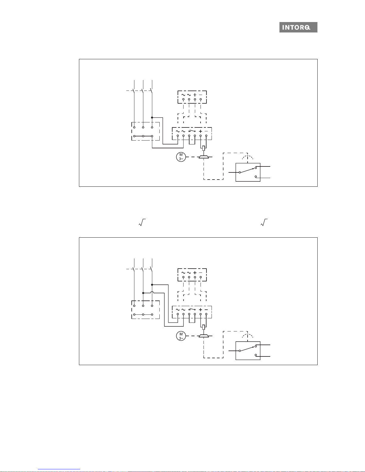
6.2 AC switching at the motor – extremely delayed engagement
Fig. 21 Supply: Phase-neutral
Bridge rectifier Half-wave rectifier
BEG-1xx: U
N
[VDC]=0.9 • [VAC] BEG-2xx: UN [VDC]=0.45 • [VAC]
Fig. 22 Supply: Phase-phase
Bridge rectifier
1)
Half-wave rectifier
BEG-1xx: U
N
[VDC]=0.9 • UV [VAC] BEG-2xx: UN [VDC]=0.45 • UV [VAC]
1)
Not recommended for most regional/national high-voltage mains systems
U2W2 V2
U
N
L1L1L2
L2
L3
L3
U
V
V1U1 W1
U
V
BN
BK
BU
4
2
1
4-pole
BEG-14x
BEG-24x
6-pole
BEG-16x
BEG-26x
U
v
3
-------- -
U
v
3
-------- -
U2W2 V2
U
N
L1L1 L2L2 L3L3
U
V
V1U1 W1
U
V
BN
BK
BU
4
2
1
4-pole
BEG-14x
BEG-24x
6-pole
BEG-16x
BEG-26x
Page 44

Electrical installation
INTORQ | BA 14.0168 | 09/2015 44
6.3 DC switching at the motor – fast engagement
Fig. 23 Supply: Phase-neutral
Bridge rectifier Half-wave rectifier
BEG-1xx: U
N
[VDC]=0.9 • [VAC] BEG-2xx: UN [VDC]=0.45 • [VAC]
Fig. 24 Supply: Phase-phase
Bridge rectifier1) Half-wave rectifier
BEG-1xx: U
N
[VDC]=0.9 • UV [VAC] BEG-2xx: UN [VDC]=0.45 • UV [VAC]
1)
Not recommended for most regional/national high-voltage mains systems
U
N
L1L1L2
L2
L3
L3
UVU
V
U2W2 V2
V1U1 W1
BN
BK
BU
4
2
1
6-pole
BEG-16x
BEG-26x
U
v
3
-------- -
U
v
3
-------- -
U2W2 V2
U
N
L1L1L2
L2
L3
L3
U
V
V1U1 W1
U
V
BN
BK
BU
4
2
1
6-pole
BEG-16x
BEG-26x
Page 45

Electrical installation
INTORQ | BA 14.0168 | 09/2015 45
6.4 AC switching at mains – delayed engagement
Fig. 25 Supply: Phase-N
Bridge rectifier Half-wave rectifier
BEG-1xx: U
N
[VDC]=0.9 • UV [VAC] BEG-2xx: UN [VDC]=0.45 • UV [VAC]
Fig. 26 Supply: Phase-phase
Bridge rectifier
1)
Half-wave rectifier
BEG-1xx: U
N
[VDC]=0.9 • UV [VAC] BEG-2xx: UN [VDC]=0.45 • UV [VAC]
1)
Not recommended for most regional/national high-voltage mains systems
U
N
L1
L1 N
U
V
BN
BK
BU
4
2
1
4-pole
BEG-14x
BEG-24x
6-pole
BEG-16x
BEG-26x
L1L1 L2L2
U
V
U
N
BN
BK
BU
4
2
1
4-pole
BEG-14x
BEG-24x
6-pole
BEG-16x
BEG-26x
Page 46
Electrical installation
INTORQ | BA 14.0168 | 09/2015 46
6.5 DC switching at mains – fast engagement
Fig. 27 Supply: Phase-phase or phase-N via 6-pole rectifier
Bridge rectifier
1)
Half-wave rectifier
BEG-16x: U
N
[VDC]=0.9 • UV [VAC] BEG-26x: UN [VDC]=0.45 • UV [VAC]
1)
For most regional/national high-voltage mains systems, this only makes sense for supplies on L1 and N.
Fig. 28 Supply: Phase-phase or phase-N via 4-pole rectifier
Bridge rectifier
1)
Half-wave rectifier
BEG-14x: U
N
[VDC]=0.9 • UV [VAC] BEG-24x: UN [VDC]=0.45 • UV [VAC]
Spark suppressor:
14.198.00.xx (required once, select position)
1)
For most regional/national high-voltage mains systems, this only makes sense for supplies on L1 and N.
U
N
L1L1 N
L1L1 L2L2
U
V
BN
BK
BU
4
2
1
6-pole
BEG-16x
BEG-26x
or
L1
L1 N
L1
L1
L2
L2
U
V
U
N
BN
BK
BU
4
2
1
4-pole
BEG-14x
BEG-24x
14.198.00.xx
or
Page 47

Electrical installation
INTORQ | BA 14.0168 | 09/2015 47
6.6 Technical specifications for the microswitch
The brake can be equipped with a microswitch for monitoring the release or wear. The microswitch can be
integrated into the circuit as an NO or NC contact.
As of June 2012, a new small microswitch (with UL acceptance) is in use, which is perfectly adapted to the
contour of the brake. The old switch design can be converted by co nnecting an adapter to the same threaded
holes.
6.7 Bridge/half-wave rectifier (optional)
BEG-561- -
The bridge/half-wave rectifiers are used to supply electromagnetic DC spring-applied brakes which are approved for the use with such rectifiers. Other use is only permitted with the approval of INTORQ.
Once a set over-excitation time has elapsed, the bridge/half-wave rectifiers switch over from bridge rectification to half-wave rectification.
Terminals 3 and 4 are located in the DC circuit of the brake. The inductio n voltage peak for DC switching
(see "DC switching - fast engagement" circuit diagram) is limited by an integrated overvoltage protection at
terminals 5 and 6.
Design Microswitch
3-pole connecting cable 3 x 0.34 mm² (AWG22)
black / brown / blue
D = 4.8 mm, black, CSA
Style 2517/105°
Length 1000 mm
Contacts Silver
Current carrying capacity 250 V AC Ma x. 3 A
Current carrying capacity 30 V DC Max. 3 A
Minimum load at 24 V DC 10 mA
Temperature range: -40 °C to +85 °C
Protection class IP67
Tab. 12: Technical specifications for the microswitch
Switching states
s
L
= 0 s
LN
s
Lmax
(-0.1)
Check of air gap 1 - 4 1 - 2 1 - 2
Monitoring wear 1 - 4 1 - 4 1 - 2
Tab. 13: Switching states of the mechanical microswitches
BN
BK
BU
4
2
1
Page 48

Electrical installation
INTORQ | BA 14.0168 | 09/2015 48
6.7.1 Assignment: Bridge/half-wave rectifier – brake size
Fig. 29 BEG-561 attachment options
Rectifier type Supply voltage Over-excitation Holding current
reduction
Coil voltage Size Coil voltage Size
[V AC] [V DC] [V DC]
BEG-561-255-030
230 103
06 ... 16
205
06 ... 14
BEG-561-255-130 – 16 ... 25
BEG-561-440-030-1 400 180 06 ... 25 – –
Page 49

Electrical installation
INTORQ | BA 14.0168 | 09/2015 49
6.7.2 Technical specifications
U
1
input voltage (40 ... 60 Hz)
6.7.3 Reduced switch-off times
AC switching must also be carried out for DC switching (fast engagement)! Otherwise, there will be no overexcitation when it is switched back on.
Rectifier type Bridge / half-wave rectifier
Output voltage for bridge rectification 0.9 x U
1
Output voltage for half-wave rectification 0.45 x U
1
Ambient temperature (storage/operation) [°C] -25 ... +70
Type Input voltage U
1
(40 Hz ... 60 Hz)
Max. current I
max
Over-excitation time tue (± 20 %)
Min.
[V ~]
Rated
[V ~]
max.
[V ~]
Bridge
[A]
half-wave
[A]
at U
1 min
[s]
at U
1 Nom
[s]
at U
1 max
[s]
BEG-561-255-030
160 230 255 3.0 1.5
0.430 0.300 0.270
BEG-561-255-130 1.870 1.300 1.170
BEG-561-440-030-1 230 400 440 1.5 0.75 0.500 0.300 0.270
Tab. 14: Data for bridge/half-wave rectifier type BEG-561
Delayed engagement Fast engagement
AA
Mains
B
Bridge
C
Coil
Page 50

Electrical installation
INTORQ | BA 14.0168 | 09/2015 50
6.7.4 Permissible current load at ambient temperature
1 For screw assembly with metal surface (good heat dissipation)
2 For other assembly (e.g. adhesive)
I
I
max.
ϑ
u
[°C]
1
2
0
0,2
0,4
0,6
0,8
1,0
-20
0
20
40 60
80
100
Page 51

Commissioning and operation
INTORQ | BA 14.0168 | 09/2015 51
7 Commissioning and operation
Usage conditions for the INTORQ spring-applied brake
7.1 Protect the electrical connections against any contact or touching.
Important notes
❚ The brake is designed for operation under the environmental conditions that apply to IP54 protection.
Because of the numerous possibilities of using the brake, it is still necessary to check the functionality
of all mechanical components under the corresponding operating conditions.
NOTICE
In case of high humidity: If condensed water and moisture are present, provide for the appropriate ventilation for the brake to ensure that all friction components dry quickly.
At high humidity and low temperatures: Take measures to ensure that the armature plate and
rotor do not freeze.
DANGER
Danger: rotating parts!
The brake must be free of residual torque.
The drive must not be running when checking the brake.
DANGER
There is a risk of injury by electrical shock!
The live connections must not be touched.
NOTICE
Functionality for different operating conditions
❚ The brakes are dimensioned in such a way that the given rated torques are reached safely
after a short run-in process.
❚ However, since the orga nic friction linings used do not all have identical properties and be-
cause environmental conditions can vary, deviations from the specified braking torques are
possible. These must be taken into account in the form of appropriate dimensioning tolerances. Increased breakaway torque is common, in particular after long downtimes in humid environments where temperatures vary.
Page 52

Commissioning and operation
INTORQ | BA 14.0168 | 09/2015 52
7.2 Function checks before commissioning
7.2.1 Function check of brake without microswitch
If a fault or malfunction arises during the function check, you can find important information for troubleshooting in the troubleshooting table 64. If the fault cannot be fixed or eliminated, please con tact your customer service.
7.2.2 Release / voltage check for brakes without microswitch
1. Remove the two bridges from the motor terminals.
-Do not disconnect the supply voltage from the brake.
- When the rectifier is connected to the neutral point of the motor: also conn ect the neutral conductor
to this connection.
2. Switch the power on.
3. Measure the DC voltage at the brake.
- Compare the measured voltage to the voltage specified on the nameplate. A deviation of up to 10%
is permitted.
4. Check the air gap "s
L
". The air gap must be zero and the rotor must rotate freely.
5. Switch the power off.
6. Connect the bridges to th e motor terminals. Remove the extra neutral conductor.
7.2.3 Release / voltage check for brakes with microswitch
Required: The switching contact for the brake must be open.
1. Make sure that the brake's switch contact is opened.
2. Remove the two bridges from the motor terminals.
-Do not disconnect the supply voltage from the brake.
- When the rectifier is connected to the neutral point of the motor: also conn ect the neutral conductor
to this connection.
3. Turn on the DC voltage for the brake.
4. Measure the AC voltage at the moto r terminal. The AC voltage must be zero.
5. Close the switching contact for the brake.
- The brake is released.
NOTICE
Operation without dynamic loads (functioning as a pure holding brake)
❚ If the brake is used as a pure holding brake without dynamic load, the friction lining must be
reactivated regularly.
Page 53

Commissioning and operation
INTORQ | BA 14.0168 | 09/2015 53
6. Measure the DC voltage at the brake.
- Compare the measured DC voltage with the voltage indicated on the nameplate. A deviation of
± 10% is permitted.
7. Check the air gap "s
L
". The air gap must be zero and the rotor must rotate freely.
7.2.4 Microswitch – checking for wear
Required: Do not turn off the power supply for the brake; the power must be switched on twice during this
testing procedure.
1. Remove the two bridges from the motor terminals.
2. Adjust the air gap to "s
Lmax
". Description: 33.
3. Switch the power on.
4. Measure the AC voltage at the motor terminals and measure the DC voltage at the brake. Both the AC
and the DC voltages must be zero.
5. Switch the power off.
6. Adjust the air gap to "s
LN
". Description: 33.
7. Switch the power on.
8. Measure the AC voltage at the motor terminal. It must be the same as the mains voltage.
9. Measure the DC voltage at the brake.
- Compare the measured DC voltage with the voltage indicated on the nameplate. A deviation of
± 10% is permitted.
10. Check the air gap "s
L
". The air gap must be zero and the rotor must rotate freely.
11. Switch off the brake current.
12. Screw the bridges back onto the motor terminals.
13. Remove the additional neutral conductor again.
NOTICE
When connecting the rectifier to the neutral point of the motor, the PE conductor must also be
connected to this point.
Page 54

Commissioning and operation
INTORQ | BA 14.0168 | 09/2015 54
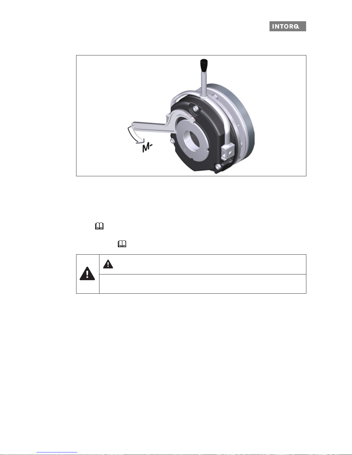
7.2.5 Test that the manual release functions
Fig. 30 Turning direction of the lever
1. Make sure that the motor and brake are de-energized.
2. Pull (with some force) on the lever until the force increases sharply.
- The rotor must now rotate freely. A small residual torque is permissible.
3. Release the lever.
- A sufficient torque must build up immediately!
The preparations for commissioning are completed.
NOTICE
This operational test is to be carried out additionally!
NOTICE
❚ Make sure that the brake it not subject to excessive force.
❚ Do not use auxiliary tools (e.g. extension pipes) to facilitate the air release. Auxiliary tools
are not permitted and are not considered as proper and intended usage.
NOTICE
If faults or malfunctions occur, refer to the the error search table ( 64). If the fault cannot be
fixed or eliminated, please contact your customer service.
Page 55

Commissioning and operation
INTORQ | BA 14.0168 | 09/2015 55
7.3 Commissioning
1. Switch on your drive system.
2. Perform a test braking procedure; if necessary, reduce the braking torque (depending on your specifications and requirements)
7.4 Operation
❚ Checks must be carried out regularly. Pay special attention to:
- unusual noises or temperatures
- loose fixing elements
- the condition of the electrical cables.
❚ Make sure that the armature plate is tightly attached and the drive moves without residual torque.
❚ Measure the DC voltage at the brake. Compare the measured DC voltage with the voltage indicated on
the nameplate. The deviation must be less than ± 10%!
DANGER
Danger: rotating parts!
❚ The running rotor must not be touched.
❚ Take structural design measures on your final product and implement organizational safety
rules to ensure that nobody can touch a rotor.
DANGER
There is a risk of injury by electrical shock!
❚ Live connections must not be touched.
❚ Take structural design measures on your final product and implement organizational safety
rules to ensure that nobody can touch a connection.
Page 56
Commissioning and operation
INTORQ | BA 14.0168 | 09/2015 56
7.4.1 Brake torque reduction
Fig. 31 Reducing the brake torque
1. Use a spanner wrench to turn the a djustment ring counter-clockwise. This reduces the braking torque.
- Note the correct position of the tappet notches on the torque adjustment ring: Only the latched-in
positions are permitted. It is forbidden to operate the br ake when the notches are adjuste d between
these latched-in positions! (Values for the brake torque reduction for each l atched-in position:
16).
- Observe the max. permissible projection ("h
Emax
") of the adjustment ring over the stator (the values
for "h
Emax
" 17).
Operating procedures
The friction lining and the friction surfaces must never contact oil or grease since even small amounts reduce
the braking torque considerably.
DANGER
The reduction of the braking torque does not increase the max. permissible air gap "s
L max.
".
Do not change the manual release setting for models with manual release.
Page 57

Maintenance and repair
INTORQ | BA 14.0168 | 09/2015 57
8 Maintenance and repair
8.1 Wear of spring-applied brakes
The table below shows the different causes of wear and their impact on the compon ents of the spring-applied
brake. The influential factors must be quantified so that the service life of the rotor and brake can be calculated and so the prescribed maintenance intervals can be specified accurately. The most important factors
in this context are the applied friction energy, the initial speed of rotation of braking and the switching frequency. If several of the causes of friction lining wear occur in an application at the same time, the influencing
factors should be added together when the amount of wear is calculated.
Component Cause Effect Influencing factors
Friction lining Braking during operation Wear of the friction lining Friction work
Emergency stops
Overlapping wear during start and stop of
drive
Active braking via the drive motor with sup-
port of brake (quick stop)
Starting wear in case of motor mounting
position with vertical shaft, even when the
brake is not applied
Number of start-stop
cycles
Armature plate and
counter friction
face
Rubbing and friction of the brake lining Run-in of armature plate
and counter friction face
Friction work
Gear teeth of brake
rotor
Relative movements and shocks between
brake rotor and brake shaft
Wear of gear teeth (primarily on the rotor side)
Number of start-stop
cycles
Armature plate
support
Load reversals and jerks in the backlash
between armature plate, adjustment tubes
and guide pins
Breaking of armature plate,
adjustment tubes and guide
pins
Number of start/stop
cycles, braking
torque
Springs Axial load cycle and shear stress of springs
through radial backlash on reversal of armature plate
Reduced spring force or
fatigue failure
Number of switching
operations of brake
Tab. 15: Causes for wear
Page 58
Maintenance and repair
INTORQ | BA 14.0168 | 09/2015 58
8.2 Inspections
To ensure safe and trouble-free operations, the spring-ap plied b rakes mu st be che cked at regu lar in tervals
and, if necessary, replaced. Servicing will be easier at the plant if the brakes are made accessible. This must
be considered when installing the drives in the plant.
Primarily, the required maintenance intervals for industrial brakes result from their load during operation.
When calculating the maintenance interval, all ca uses for wear must be taken into account, 57. For
brakes with low loads (such as holding brakes with emerge ncy stop function), we recommend a regular inspection at a fixed time interval. To reduce costs, the inspection can be carried out along with other regular
maintenance work in the plant.
Failures, production losses or damage to the system may occur when the brakes are not serviced. Therefore,
a maintenance strategy that is adapted to the particular operating conditions and brake loads must be defined for every application. For the spring-applied brakes, the maintenance intervals and maintenance operations listed in the table below must be followed. The maintenance opera ti on s must be carried out as
described in the detailed descriptions.
8.2.1 Maintenance intervals
1)
Attention: 10 million cycles for the L design
8.3 Maintenance
Versions Service brakes Holding brakes with emergency stop:
BFK458- E / N
BFK458- L
❚ according to the service life calcu-
lation
❚ or else every six months
❚ after 4000 operating hours at the
latest
❚ at least every two years
❚ after 1 million cycles at the latest
1)
❚ plan shorter intervals for frequent
emergency stops
NOTICE
Brakes with defective armature plates, springs or flanges must be completely replaced.
Observe the following for inspections and maintenance works:
❚ Contamination by oils and greases should be removed using brake cleaner, or the brake
should be replaced after determining the cause. Dirt and particles in the air gap between the
stator and the armature plate endanger the function and should be removed.
❚ After replacing the rotor, the original braking torque will not be reached until the run-in oper-
ation for the friction surfaces has been completed. After re placing the rotor, the run-in armature plates and the flanges have an increased initial rate of wear.
Page 59

Maintenance and repair
INTORQ | BA 14.0168 | 09/2015 59
8.3.1 Checking the component parts
8.3.2 Check the rotor thickness
1. Remove the fan cover.
2. Remove the cover ring, when pre s ent.
3. Measure the rotor thickness using a calliper gauge. For the friction-plate version: observe the edging on
outer diameter of friction plate.
4. Compare the measured rotor thickness with the minimum permissible rotor thickness (values: 17).
If the measured rotor thickness is insufficient, the rotor must be replaced completely.
Description: 61.
8.3.3 Check the air gap
1. Measure the air gap "s
L
" between the armature plate and the stator near the fixing screws using a feeler
gauge (values: 17).
2. Compare the measured air gap to the value for the max. permissible air gap "s
Lmax
" (values: 17).
3. Adjust the air gap to "s
LN
" ( 60).
With mounted brake
❚ Check release function and control
❚ Measure the air gap (adjust if required)
❚ Measure the roto r thickness (replace rotor if required)
❚ Thermal damage of armature plate or flange (dark-blue tar-
nishing)
60
60
59
After removing the brake
❚ Check the play of the rotor gear teeth (replace worn-out
rotors)
61
❚ Check for breaking out of the torque support at the sleeve
bolts and the armature plate
❚ Check the springs for damage
❚ Check the armature plate and flange or bearing shield
- Evenness depending on the size
- Max. run-in depth = rated air gap for the size
29
17
DANGER
Danger: rotating parts!
The motor must not be running when checking the rotor thickness.
DANGER
Danger: rotating parts!
The motor must not run while the air gap is being checked.
Page 60
Maintenance and repair
INTORQ | BA 14.0168 | 09/2015 60
8.3.4 Release / voltage
1. Check the brake functionality when the drive is running: The armature plate must be tightened and the
rotor must move without residual torque.
2. Measure the DC voltage at the brake.
- The DC voltage measured after the over-excitation time (see bridge/half-wave rectifier) must be half
the voltage indicated on the nameplate. The devia tion must be less than ± 10%.
8.3.5 Adjusting the air gap
1. Loosen the screws (Figure 12).
2. Screw the sleeve bolts (using a wrench) furthe r into the stator. A 1/6 turn will decrease the air gap by
approximately 0.15 mm.
3. Re-tighten the screws (torque: 18).
4. Check the "s
L
" near the screws using a feeler gauge (sLN: 17).
DANGER
Danger: rotating parts!
The running rotor must not be touched.
DANGER
There is a risk of injury by electrical shock!
Live connections must not be touched.
DANGER
Danger: rotating parts!
The brake must be free of residual torque.
NOTICE
Please observe when mounting the flange with additional screw s:
Clearing holes for the screws in the end shield must be behind the threaded screw holes in
the flange. Without the clearing holes, the minimal rotor thickness cannot be used. The
screws must not press against the end shield.
Page 61

Maintenance and repair
INTORQ | BA 14.0168 | 09/2015 61
8.3.6 Replacing the rotor
1. Remove the connecting cables.
2. Loosen the screws evenly and then remove them.
3. Pay attention to the connecting cable during this step! Remove the complete stator from the end shield.
4. Pull the rotor off the hub.
5. Check the hub's gear teeth.
6. Replace the hub if wear is visible.
7. Check the end shield's friction surface. Replace the friction surface on the end shield when there is clearly visible scoring at the flange. In case of strong scoring on the end shield, rework the friction surface.
8. Measure the rotor thickness of the new rotor and the head height of the sleeve bolts (use a calliper
gauge).
9. Calculate the distance between the stator and the armature plate as follows:
Distance = rotor thickness + s
LN
- head height
"s
LN
" 17
10. Unscrew the sleeve bolts evenly until the calculated distance between the stator and armature plate is
reached.
11. You can now install and adjust the new rotor and the complete stator ( 32).
12. Re-connect the connecting cables.
DANGER
Danger: rotating parts!
Switch off the voltage. The brake must be free of residual torque.
Page 62

Maintenance and repair
INTORQ | BA 14.0168 | 09/2015 62
8.4 Spare-parts list
Spring-applied brake INTORQ BFK458-06 to 25
Designation Variant
Complete stator, module E
Complete stator, module N
Voltage / braking torque
Complete rotor Aluminium rotor
Aluminium rotor with sleeve
- Low-noise version
Hub Hole diameter [mm] slot according to DIN 6885/1
Flange
Hard chrome-plated flange
Centring flange (tacho flange)
Friction plate
Cover ring
Shaft sealing ring
Cap
Manual release
Brake cover
(degree of protection corresponds to IP65)
Terminal box as mounting kit
Screw set: DIN EN ISO 4762 - 8.8
in various designs and lengths
❚ for mounting to the flange
❚ for mounting to the motor / friction plate
❚ for flange with through hole
Page 63

Maintenance and repair
INTORQ | BA 14.0168 | 09/2015 63
Double spring-operated brake INTORQ BFK458-06 to 25
Electrical accessories
Designation Variant
Complete stator, module N Voltage / braking torque
- Optionally with rear threads
Complete rotor Aluminium rotor
Aluminium rotor with sleeve
- Low-noise version
Hub with standard bore Hole diameter [mm] slot according to DIN 6885/1
Flange
Hard chrome-plated flange
Connection flange for double brake
Friction plate
Shaft sealing ring Shaft diameter on request
Cover ring
Cap Basic module N
Manual release with standard lever Mounting kit
Screw set; socket head cap screw
DIN EN ISO 4762 8.8 / size 25 10.9
for connection flange / double brake
Screw set: DIN EN ISO 4762 - 8.8
in various designs and lengths
❚ for mounting to the flange
❚ for mounting to the motor / friction plate
❚ for flange with through hole
Bridge / half-wave rectifier
Supply voltage Over-excitation Holding current
reduction
Coil
voltage
Size Coil
voltage
Size
[V AC] [V DC] [V DC]
BEG-561-255-030
230 103
06 ... 16
205
06 ... 14
BEG-561-255-130 – 16 ... 25
BEG-561-440-030-1 400 180 06 ... 25 – –
Page 64

Troubleshooting and fault elimination
INTORQ | BA 14.0168 | 09/2015 64
9 Troubleshooting and fault elimination
If any malfunctions should occur during operations, please ch eck for possible causes based on the following
table. If the fault cannot be fixed or eliminated by one of the listed measures, please contact customer service.
Fault Cause Remedy
Brake cannot be released,
air gap is not zero
Coil interruption ❚ Measure the coil resistance using a multimeter:
- If resistance is too high, replace the complete springapplied brake.
Coil has contact to earth or
between windings
❚ Measure the coil resistance using a multimeter:
- Compare the measured resistance with the nominal
resistance. Refer to 19 for the values. If resistance is too low, replace the complete stator.
❚ Check the coil for short to ground using a multimeter:
- If there is a short to ground, replace the complete
spring-applied brake.
❚ Check the brake voltage (refer to section on defective
rectifier, voltage too low).
Wiring defective or wrong ❚ Check the wiring and correct.
❚ Check the cable for contin uity using a multimeter:
- Replace defective cable.
Rectifier defective or incorrect ❚ Measure rectifier DC voltage using a multimeter.
If DC voltage is zero:
❚ Check AC rectifier voltage.
If AC voltage is zero:
- Switch on power supply.
- Check fuse.
- Check wiring.
If AC voltage is OK:
- Check rectifier.
- Replace the defective rectifier.
- Diode is defective; use a suitable new rectifier.
❚ Check the coil for winding short or groun d sh ort.
❚ If the rectifier defect occurs again, replace the entire
spring-applied brake, even if you cannot find any fault
between turns or short circuit to ground. The error may
only occur on warming up.
Brake cannot be released,
air gap is not zero
Incorrect micro-switch wiring Check the wiring of the micro-switch and correct it.
Micro-switch incorrectly set Replace the complete stator and make a complaint about
the setting of the microswitch to the manufacturer.
Air gap "s
L
" is too large
Adjust the air gap: 60.
Page 65
Troubleshooting and fault elimination
INTORQ | BA 14.0168 | 09/2015 65
Rotor cannot rotate freely Wrong setting of manual
release
Check the dimension "sLN + sHL" with the brake energised.
The dimension must be the same on both sides. Correct if
required ( 41).
Air gap "s
L
" too small
Check air gap "s
L
" and adjust if necessary ( 60).
Rotor thickness too small Rotor has not been replaced
in time
Replace the rotor ( 61).
Voltage too high Brake voltage does not match
the rectifier
Adjust rectifier and brake voltage to each other.
Voltage too low Brake voltage does not match
the rectifier
Adjust rectifier and brake voltage to each other.
Defective rectifier diode Replace defective rectifier with a suitable undamaged one.
AC voltage is not mains
voltage
Fuse is missing or defective Select a connection with proper fusing.
Fault Cause Remedy
Page 66

Notes
INTORQ | BA 14.0168 | 09/2015 66
Notes
Page 67

Page 68

www.intorq.com
13343893 | BA 14.0168 | EN | 6.0 | ©09.2015 | SC |
INTORQ GmbH & Co KG
Germany
PO Box 1103
D-31849 Aerzen, Germany
Wülmser Weg 5
D-31855 Aerzen, Germany
+49 5154 70534-444
+49 5154 70534-200
info@intorq.com
INTORQ (SHANGHAI) Co., Ltd
China
No. 600, Xin Yuan Road
Building No. 6 / Zone B
Nan Hui District, Lingang
Shanghai, China 201306
应拓柯制动器 (上海)有限公司
中国
新元南路 600 号 6 号楼 1 楼 B 座
上海 南汇 201306 201306
+86 21 20363-810
+86 21 20363-805
info@cn.intorq.com
INTORQ US Inc.
USA
300 Lake Ridge Drive SE
Smyrna, GA 30082, USA
+1 678 309-1155
+1 678 309-1157
info@us.intorq.com
INTORQ India Private Limited
India
Plot No E-7/3
Chakan Industrial Area, Phase 3
Nighoje, Taluka - Khed
Pune, 410501, Maharashtra, India
+91 2135625500
info@intorq.in
 Loading...