

Page 1
j
setting the standard
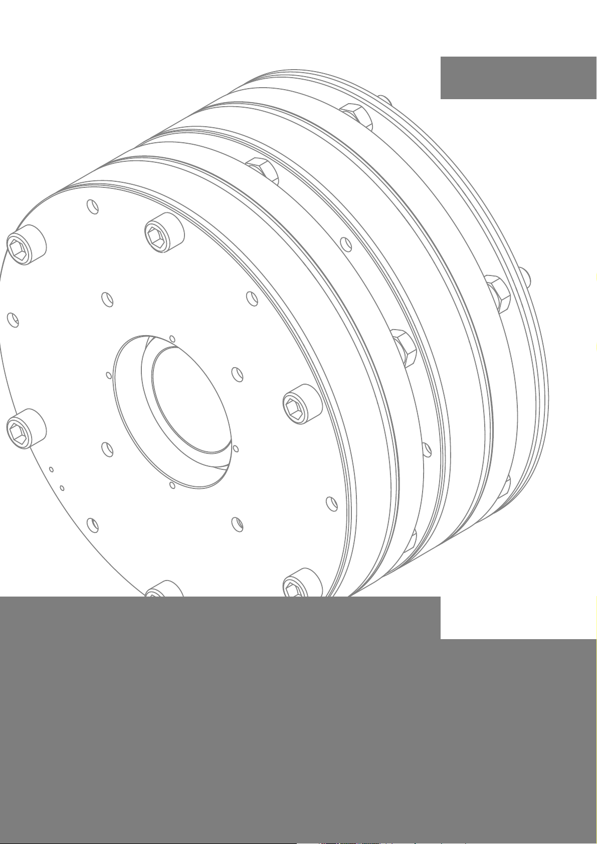
INTORQ BFK455
Electromagnetically released spring-applied brake
Operating Instructions
www.intorq.com
Page 2

j | BA 14.0196 | 05/2013
This documentation applies to ...
BFK455 -28 - dou bl e -disk version
BFK455-001.iso/dms BFK455-020.iso/dms
Product key
Product key INTORQ B FK
Legend for the INTORQ BFK455 product key
Product group Brakes
Product type Spring-applied brake
Type 455
Size 28
Not coded: supply voltage, hub bore, options
-
2
Page 3
j | BA 14.0196 | 05/2013
i
Identification
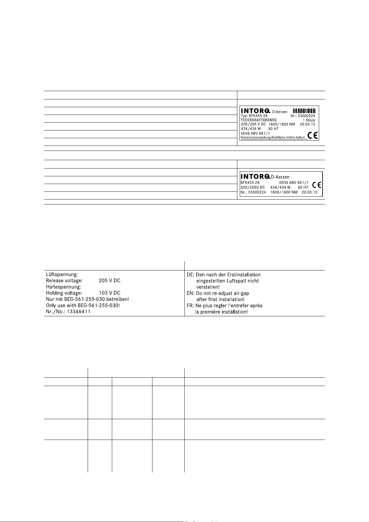
Package label Example
Manufacturer Bar code
Type (see product key) Type No.
Name Quantity per box
Rated voltage Rated torque Packing date
Rated power Hub diameter
Additional information CE designation
Nameplate Example
Manufacturer
Type (see product key) CE designation
Rated voltage Rated power Hub diameter
Type No. Rated torque Production date
BFK455-101.iso/dms
BFK455-002.iso/dms
Notes
The brake is marked with the following labels, which have to be observed:
for holding voltage for air gap setting
Document history
Material number Version Description
33000803 1.0 05/2011 TD09 First edition
33000803 1.1 05/2012 TD09 Change in telephone and fax number
Front and back page new
Addition of the EC type test number
Supplemented by chapter ”Project planning notes”
Supplemented by chapter ”Wear of spring-applied brakes”
33002468 2.0 03/2013 TD09 Amended by new chapter on hand-release installation
Tables of dimensions and operating times were changed
Amendment of the spare parts list and the spare parts order
33002468 3.0 05/2013 TD09 Limitation of the adjustability
Note on the suppressor circuit added to the ”Electrical
installation” chapter
Values for characteristic torque 2x2065 Nm added to
”Dimensions” table
0Fig.0Tab. 0
3
Page 4

j | BA 14. 0196 | 05/2013
Contentsi
1 Preface and general information 6.......................................
1.1 About these Operating Instructions 6...................................
1.2 Terminology used 6.................................................
1.3 Conventions used 6.................................................
1.4 Abbreviations used 7................................................
1.5 Notes used 8......................................................
1.6 Scope of supply 9..................................................
1.7 Disposal 9........................................................
1.8 Drive systems 9....................................................
1.9 Legal regulations 10.................................................
2 Safety instructions 11...................................................
2.1 General safety information 11..........................................
2.2 Application as directed 12............................................
3Technicaldata 13.......................................................
3.1 Product description 13...............................................
3.2 Rated data 16......................................................
3.3 Rated data (selection data) 17.........................................
3.4 Friction work / operating frequency 19..................................
3.5 Emission 20.......................................................
4 Mechanical installation 21................................................
4.1 Important notes 21..................................................
4.2 Necessary tools 21..................................................
4.3 Mounting 21.......................................................
4.4 Installation 22......................................................
4.5 Manual release 28..................................................
4.6 Assembly of the cover ring 34..........................................
5 Electrical installation 35.................................................
5.1 Electrical connection 35..............................................
5.2 Bridge/half-wave rectifiers ( opti on ) 36...................................
5.3 Electrical connection 38..............................................
6 Commissioning and operation 39..........................................
6.1 Important notes 39..................................................
6.2 Function checks before commissioning 39................................
6.3 Commissioning 40...................................................
6.4 During operation 41.................................................
4
Page 5

i
j | BA 14. 0196 | 05/2013
Contentsi
7 Maintenance/repair 42..................................................
7.1 Wear of spring-applied brakes 42.......................................
7.2 Inspections 43......................................................
7.3 Maintenance operations 44............................................
7.4 Spare-parts list 46..................................................
7.5 Spare parts order 47................................................
8 Troubleshooting and fault elimination 48...................................
5
Page 6

j | BA 14.0196 | 05/2013
Preface and general information1
1 Prefaceand generalinformatio n
1.1 About these Operating Instructions
| These Operating Instructions will help you to work safely on and with the
spring-applied brake with electromagnetic release. They contain safety instructions
that must be followed.
| All persons working on or with the electromagnetically released spring-applied brakes
must have the Operating Instructions available and observe the information and notes
relevant for them.
| The Operating Instructions must always be in a complete and perfectly readable
condition.
1.2 Terminology used
1.3 Conventions used
This documentation uses the following conventions to distinguish different types of
information:
Spelling of numbers Decimal separator Point The decimal point is always used.
Symbols
Term In the following text used for
Spring-applied brake Spring-applied brake with electromagnetic release
Drive system Drive systems with spring-applied brakes and other drive
components
For example: 1234.56
Page reference Reference to another page with additional information
For example: 16 = see page 16
Document reference Reference to another documentation with additional
information
For example: Operating instructions
Wildcard Wildcard for options, selections
For example: BFK458- = BFK458-10
6
Page 7

Preface and general information1
i
1.4 Abbreviations used
Abbreviation Unit Name
I A Current
I
H
I
L
I
N
M
A
M
K
n
max
P
H
P
L
P
N
Q J Heat/energy
Q
E
Q
R
Q
Smax
R
N
S
h
S
hue
S
hmax
s
L
s
LN
s
Lmin
s
Lmax
t
1
t
2
t
11
t
11
t
12
t
ue
U V Voltage
U
H
U
L
U
N
j | BA 14.0196 | 05/2013
A Holding current at 20 °C and holding voltage
A Release current at 20 °C and release voltage
A Rated current at 20 °C and rated voltage
Nm Tightening torque of the fixing screws
Nm Rated torque of brake, rated value at a relative speed of 100 rpm
rpm Maximum speed during the slipping time t3
W Coil power during holding, through normal excitation and 20 °C
W Coil power during release, through normal excitation and 20 °C
W Rated coil power at rated voltage and 20 °C
J Max. permissible friction work per switching cycle, thermal rating of
the brake
J Braking energy, friction work
J Max. permissible friction work during cyclic switching, depending on
the operating frequency
Ohm Rated coil resistance at 20 °C
1/h Operating frequency, the number of repeated operations per unit
time
1/h Transitional operating frequency, thermal rating of the brake
1/h Maximum permissible operating frequency, depending on the
friction work per operation
mm Air gap, movement of armature plate by switching the brake
mm Rated air gap
mm Minimum air gap
mm Maximum air gap
ms Engagement time, the total of the reaction delay and torque rise
time t
1=t11+t12
ms Disengagement time, time from switching the stator until the torque
has reduced to 0.1 M
K
ms Slipping time to standstill (after t11)
ms Delay time when connecting, time from disconnecting the
voltage until the torque begins to rise
ms Rise time of braking torque, time from beginning of rise of torque
until braking torque is reached
S Overexcitation time
VDC Holding voltage by change of voltage
VDC Release voltage by change of voltage
VDC Rated coil voltage for brakes which require automatic voltage
changing, the rated coil voltage U
voltage U
L
isthesameastherelease
rated
7
Page 8

j | BA 14.0196 | 05/2013
Preface and general information1
1.5 Notes used
The following pictographs and signal words are used in this documentation to indicate dangers
and important information:
Safety instructions
Structure of safety instructions:
Danger!
Characterises the type and severity of danger
Note
Describes the danger
Possible consequences:
| List of possible consequences if the safety instructions are disregarded.
Protective measure:
| List of protective measures to avoid the danger.
Pictograph and signal word Meaning
Danger of personal injury through dangerous electrical voltage
Danger!
Danger!
Stop!
Application notes
Pictograph and signal word Meaning
Note!
Tip!
Reference to an imminent danger that may result in death or serious
personal injury if the corresponding measures are not taken.
Danger of personal injury through a general source of danger
Reference to an imminent danger that may result in death or serious
personal injury if the corresponding measures are not taken.
Danger of property damage
Reference to a possible danger that may result in property damage if the
corresponding measures are not taken.
Important note to ensure troublefree operation
Useful tip for simple handling
Reference to another documentation
8
Page 9

Preface and general information1
i
1.6 Scope of supply
After receipt of the delivery, check immediately whether it corresponds to the accompanying
papers. INTORQ does not grant any warranty for deficiencies claimed subsequently.
| Claim visible transport damage immediately to the forwarder.
| Claim visible deficiencies / incompleteness immediately to INTORQ GmbH & Co.KG.
1.7 Disposal
The spring-applied brake consists of different types of material.
| Recycle metals and plastics.
j | BA 14.0196 | 05/2013
| Ensure professional disposal of assembled PCBs according to applicable
environmental regulations.
1.8 Drive systems
Labelling
Drive systems and components are unambiguously designated by the indications on the
nameplate.
Manufacturer: INTORQ GmbH & Co KG, Wülmser Weg 5, D-31855 Aerzen
| The spring-applied INTORQ brakeis also delivered in single modules and individually
combined to its modular design. The data - package labels, nameplate, and type code
in particular - apply to one complete stator.
| If single modules are delivered, the labelling is missing.
9
Page 10

j | BA 14.0196 | 05/2013
Preface and general information1
1.9 Legal regulations
Liability
| The information, data and notes in this documentation met the state of the art at the
time of printing. Claims referring to products which have already been supplied cannot
be derived from the information, illustrations and descriptions.
| We do not accept any liability for damage and operating interference caused by:
– inappropriate use
– unauthorised modifications to the product
– improper working on and with the product
– operating faults
– disregarding the documentation
Warranty
| Terms of warranty: see terms of sale and delivery of INTORQ GmbH & Co. KG.
| Warranty claims must be made to INTORQ immediately after detecting defects or
faults.
| The warranty is void in all cases where liability claims cannot be made.
10
Page 11

Safety instructions2
i
2 Safetyinstructions
2.1 General safety information
| INTORQ components ...
– ... must only be applied as directed.
– ... must not be commissioned if they are noticeably damaged.
– ... must not be technically modified.
– ... must not be commissioned if they are mounted and connected incompletely.
– ... must not be operated without the required covers.
– ... can hold live as well as moving or rotary parts during operation according to their
degree of protection. Surfaces may be hot.
| For INTORQ components ...
– ... the documentation must always be kept at the installation site.
– ... only permitted accessories are allowed to be used.
– ... only original spare parts of the manufacturer are allowed to be used.
j | BA 14.0196 | 05/2013
| All specifications of the corresponding enclosed documentation must be observed.
This is vital for a safe and trouble-free operation and for achieving the specified product
features.
| Only qualified, skilled personnel are permitted to work on and with INTORQ
components.
In accordance with IEC 60364 or CENELEC HD 384, qualified, skilled personnel are
persons ...
– ... who are familiar with the installation, mounting, commissioning, and operation of
the product.
– ... who have the qualifications necessary for their occupation.
– ... who know and apply all regulations for the prevention of accidents, directives, and
laws relevant on site.
|Riskofburns!
– Surfaces may be hot during operation! Provide for protection against accidental
contact.
| Risk of injury due to a rotating shaft!
– Wait until the motor is at standstill before you start working on the motor.
| The friction lining and the friction surfaces must by no means have contact to oil or
grease since even small amounts reduce the brake torque considerably.
| The brake is designed for operation under the environmental conditions that apply to
IP54. Because of the numerous possibilities of using the brake, it is however necessary
to check the functionality of all mechanical components under the corresponding
operating conditions.
11
Page 12

j | BA 14.0196 | 05/2013
Safety instructions2
2.2 Application as directed
| INTORQ components ...
– ... are intended for use in machinery and systems.
– ... must only be used for the purposes ordered and confirmed.
– ... must only be operated under the ambient conditions prescribed in these
Operating Instructions.
– ... must not be operated beyond their corresponding power limits.
Any other use shall be deemed inappropriate!
Possible applications of the INTORQ spring-applied brake
| Humidity: no restrictions
– In case of formation of condensed water and moisture: provide for appropriate
ventilation to ensure that all components will dry quickly.
| Ambient temperature:
-5 °C to +40 °C
| At high humidity and low temperature:
– Take measures to protect armature plate and rotor from freezing.
| Protect electrical connections against contact.
12
Page 13
Technical data3
i
3Technicaldata
3.1 Product description
Versions
Basic module
j | BA 14.0196 | 05/2013
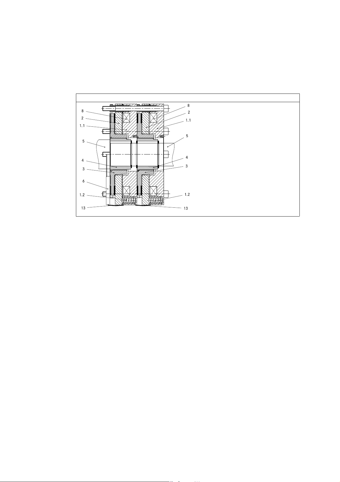
Fig. 1 Design of a BFK455 spring-applied brake
1.1 Stator 3 Complete rotor 6 Flange
1.2 Compression springs 4 Hub 8 Coil
2Armatureplate 5Shaft 13Coverring
3.1.1 General information
The spring-applied brake is designed for the conversion of mechanical work and kinetic energy
into heat. Due to the static brake torque, the brake can hold loads without speed difference.
Emergency braking is possible at high speed. The more friction work, the higher t he wear,
(operating speeds 16).
The BFK455 spring-applied brake is a double disc brake with four friction surfaces. The braking
torque is generated within two electrically and mechanically separated braking circuits by
means of several compression springs (1.2) with friction locking. The braking circuits are
released electromagnetically. Due to its division into two braking circuits, the brake is
especially suitable for applications in the fields of lift technology and stage machinery. The
brake is selected on the basis of the characteristic torque for one braking circuit. The second
braking circuit meets the requirement for redundancy.
The braking circuits are divided by two separate armature plates (2) with the respective
compression springs (1.2) assigned and electromagnetic coils (8). The separate connecting
cables for each stator and armature plate render it possible to switch each braking circuit
individually, 36.
BFK455-005.iso/dms
13
Page 14
j | BA 14.0196 | 05/2013
Technical data3
The switching status of the spring-appliedbrake is monitored by one microswitch (16) for each
braking circuit. The associated switchgear rectifies the supply voltage (AC voltage) which is
reduced after a short time while the brake is in the released state. Thus the mean electrical
power of the brake is reduced.
The stator (1) is designed in temperature class F. The temperature limit of the coils (8) is
155 °C. The BFK455 spring-applied brake is designed for a maximum operating time of 60 %
with a reduction of the holding current.
Certificate
Type Characteristic torque [Nm] EC type-examination certificate
BFK455-28
2 x 1100, 2 x 1200
2 x 1700, 2 x 1800
2 x 2065
ABV 881/1
3.1.2 Braking
During braking, the rotor (3), which is axially movable on the hub (4), is pressed against
the friction surface - via the armature plates (2) - by means of the springs (1.2). The
asbestos-free friction linings ensure a high braking torque with low wear. The braking
torque is transmitted between hub (4) and rotor (3) via the splines.
3.1.3 Brake release
In braked state, there is an air gap ”s
release the brake, the coil of the stator (1) is excited with the DC voltage provided. The
magnetic force generated attracts the armature plate (2) towards the stator (1) against the
spring force. The rotor (3) is then released and can rotate freely.
3.1.4 Release monitoring
The spring-applied brake is equipped with one microswitch (16) each per braking circuit
for monitoring the switching status. When the braking circuits are released, the
microswitches (16) change over. This means that the operation of the drive against the
applied brake can be excluded. The microswitches can be connected both as NO and NC
contacts.
” between the stator (1) and the armature plate (2). To
L
For checking the correct functioning of the microswitches, we recommend to check the
switching status (see Tab. 6) both when the brake is released and when the brake is
applied.
3.1.5 Encapsulated design (optional)
This design not only avoids the penetration of spray water and dust, but also the spreading
of abrasion particles outside the brake. This is achieved by:
| a cover seal over the armature plate and rotor.
14
Page 15

Technical data3
i
3.1.6 Project planning notes
| The brakes are dimensioned in such a way that the given characteristic torques are
reached safely after a short run-in process.
| Due to the fluctuating properties of the organic friction linings used and the alternating
environmental conditions, deviations of the given braking torques may occur. These
must be considered by corresponding safety measures in the dimensioning process.
Especially with humidity and alternating temperatures, an increased breakaway torque
may occur after a long downtime.
| If the brake is used as a pure holding brake without dynamic load, the friction lining
must be reactivated regularly.
j | BA 14.0196 | 05/2013
15
Page 16

j | BA 14.0196 | 05/2013
Technical data3
3.2 Rated data
3.2.1 Dimensions
BFK455-006.iso/dms
Type Character
BFK455-28
Type
BFK455-28 314 M16 6 x M16x210 6 x M16x220 25 22.5 206 265
istic
torque
[Nm] s
2 x 1100
2 x 1200
2 x 1700
2 x 1800
2 x 2065 0.6 0.2 17.8
Pitch circle
∅[mm] Thread [mm] [mm] [mm] [mm] MA[Nm] MA[Nm]
Tab. 1 Dimensions of the BFK455-28
LN
Air gap Perm. wear Rotor thickness Mass
+0.05
[mm] s
0.4
Fixing screws DIN 912 Minimum thread depth
without
flange
[mm] [mm] min. [mm] max. [mm] m[kg]
Lmax.
0.7 0.3 17.7
+1.0 mm
with flange without
flange
with flange without
18 46
flange
of complete
stator
Tightening torque
with flange
Stop!
| The minimum thread depth of the end shield must be observed in any case,
Tab. 1
| If the required thread depth is not observed, the fixing screws may run into
the thread root. As a result, the required preload force will no longer be built
up and the brake will no longer be fixed securely!
16
Page 17

Technical data3
i
3.2.2 Electrical data
j | BA 14.0196 | 05/2013
Type Voltage Power Coil
resistance
Release ±10% Holding ±10% Release Holding
UL[V] DC UH[V] DC PN[W] PH[W] RN±5% [Ω] IL[A]
103 52 2 x 434 2 x 108.5 2 x 24.5 2 x 4.21
BFK455-28
205 103 2 x 434 2 x 108.5 2x97 2 x 2.12
360 180 2 x 434 2 x 108.5 2 x 298.6 2 x 1.21
Tab. 2 Coil power ratings of the BFK455-28
3.3 Rated data (selection data)
Current
Fig. 2 Operating times of the spring-applied brakes
t
1
t
2
M
Type Rated torque
M
K
[Nm] [J] [h-1]
2 x 1100
2 x 1200 60 280
BFK455-28
2 x 1700
2 x 1800
2 x 2065 30 250 460
1)
Minimum brake torque when all components are run in with Δn=100 rpm
2)
Typical values
3)
Max. speed according to EC type -examination certificate (for higher speeds contact the manufacturer)
4)
Measured with induced voltage limitation -800 V DC
Tab. 3 Switching energy - operating frequency - operating times
Engagement time t
Reaction delay during engagement
11
Disengagement time (up to M = 0.1 Mr)t12Rise time of the brake torque
Characteristic torque U Voltage
K
1)
Max. perm.
switching
energy
QE S
360000 7
Transition
operating
frequency
hue
Operating times [ms]
at sLNand 0.7 I
DC engagement
t
11t12
80
20 240 480
t
300
220
4)
1
N
Disengage
370
BFKXXX-011.iso/dms
2)
t
2
Max. speed
n
3)
max.
[rpm]
455
17
Page 18

j | BA 14.0196 | 05/2013
Technical data3
Engagement time
The transition from brake-torque free state to holding braking torque is not free of time lags.
Short brake engagement times are vital for emergency braking. DC switching together with
a suitable spark suppressor must therefore be provided.
| The engagement times are valid for DC switching with a spark suppressor.
– Spark suppressors are available for the rated voltages.
– Connect the spark suppressors in parallel to the contact. If this is not admissible for
safety reasons, e.g. with hoists and lifts, the spark suppressor can also be
connected in parallel to the brake coil.
– Circuit proposals: 36
| If the drive system is operated with a frequency inverter so that the brake will not be
deenergised before the motor is at standstill, AC switching is also possible (not
applicable to emergency braking).
Note!
If the drive system is equipped with a frequency inverter, the engagement times
are greater by a factor of 5, approximately, connection 35.
Disengagement time
The disengagement time is the same for DC and AC switching. The disengagement times
specified always refer to the control with overexcitation.
18
Page 19

Technical data3
i
3.4 Friction work / operating frequency
j | BA 14.0196 | 05/2013
BFK455-003.iso/dms
Fig. 3 Switching energy as a function of the operating frequency
−p
− p
p
Üã~ñ
=
äåN −
ÜìÉ
n
n
o
n
b
ëã~ñ
The permissible operating frequency S
If the operating frequency S
is specified, the permissible quantity of heat Q
h
= n
hmax
N − É
b
depends on the quantity of heat QR(see Fig. 3).
ÜìÉ
p
Ü
will result.
smax
With high speed and friction work, the wear increases strongly, because very high
temperatures occur at the friction faces for a short time.
19
Page 20

j | BA 14.0196 | 05/2013
Technical data3
3.5 Emission
Electromagnetic compatibility
Note!
If an INTORQ rectifier is used for the DC switching of the spring-applied brake and if the
operating frequency exceeds five switching operations per minute, the use of a mains filter
is required.
If the spring-applied brake uses a rectifier of another manufacturer for the switching, it
may become necessary to connect a spark suppressor in parallel with the AC voltage.
Spark suppressors are available on request, depending on the coil voltage.
The user must ensure compliance with EMC Directive 2004/108/EC using
appropriate controls and switching devices.
Heat
Since the brake converts kinetic energy as well as mechanical and electrical energy into heat,
the surface temperature varies considerably, depending on the operating conditions and
possible heat dissipation. Under unfavourable conditions, the surface temperature can reach
130 _C.
Noise
The switching noise during engagement and disengagement varies depending on the air gap
” and the brake size.
”s
L
Depending on the natural oscillation after installation, operating conditions and state of the
friction faces, the brake may squeak during braking.
Others
The abrasion of the friction parts produces dust.
20
Page 21

Mechanical installation4
i
4 Mechanicalinstallatio n
4.1 Important notes
Stop!
Toothed hub and screws must not be lubricated with grease or oil!
4.2 Necessary tools
j | BA 14.0196 | 05/2013
Type Torque key
Insert for hexagon socket screws
Measuring range [Nm] Wrench size [mm] Adjustment tubes - wrench
BFK455-28 40 - 250 14 24
Feeler gauge Caliper gauge Multimeter
Open-jawed spanner
size [mm]
4.3 Mounting
4.3.1 Important notes
Brake size Minimum requirements for the counter friction face
28
1)
In case of other materials please consult INTORQ.
Tab. 4 Counter friction face design of the end shield
The diameter of the shaft shoulder must not be bigger than the tooth root diameter of the hub.
Material
S235 JR
C15
EN -GJ L -25 0
1)
Evenness Axial runout Roughness Others
[mm] [mm]
<0.1 0.1 Rz10
| Threaded holes with
minimum thread depth
16
| Free of grease and oil
21
Page 22

j | BA 14.0196 | 05/2013
Mechanical installation4
4.3.2 Preparation
1. Unpack spring-applied brake.
2. Check for completeness.
3. Check nameplate data, especially rated voltage.
4.3.3 Overview
without separate counter friction face with flange
4.4 Installation
Stop!
Toothed hub and screws must not be lubricated with grease or oil!
Note!
When you have ordered a version with flange, attach the hub first ( 23), then
continue with the ”Assembly of the counter friction faces”.
BFK455-007.iso/dms BFK455-008.iso/dms
22
Page 23

Mechanical installation4
i
4.4.1 Brake assembly
Mounting the first hub onto the shaft
4 Hub 4.1 Keyway 15 End shield
j | BA 14.0196 | 05/2013
BFK455-009.iso/dms BFK455-010.iso/dms
1. Insert keyway (4.1) into the shaft.
2. Press the first hub (4) onto the shaft.
3. Secure hub (4) against axial displacement, e.g. by using a circlip (4.2).
Stop!
In reverse operation, it is recommended to additionally glue the hub to the shaft!
Assembly of the counter friction faces
Flange (option)
BFK455-011.iso/dms
Fig. 4 Assembly of the flange
4 Hub 15 End shield
6Flange
4. Hold the flange (6) to the end shield (15).
5. Align the through holes in the flange to the threads of the fastening bore holes.
In the following sections, only assembly for the version with flange will be
described.
23
Page 24

j | BA 14.0196 | 05/2013
Mechanical installation4
Assembly of the first rotor
Fig. 5 Mounting of the rotor
BFK455-012.iso/dms
3 Rotor 6 Flange 15 End shield
4Hub
6. Push the rotor (3) onto the hub (4) and check whether it can be moved by hand.
Stop!
Only in the case of rotors with mounting paste on their gear teeth:
| Remove cover films from both front ends of the rotor.
| Protect friction surfaces against contact with mounting paste!
| After the mounting, excessive mounting paste must be removed properly!
Installation of the second hub onto the shaft
24
BFK455-013.iso/dms
Fig. 6 Mounting of the second hub
4 Hub 3 Complete rotor 4.2 Circlip
5Shaft 4.1Keyway
7. Insert second keyway (4.1) into the shaft (5) if required.
8. Press second hub (4) onto the shaft (5).
9. Secure hub (4) against axial displacement, e.g. by using a circlip (4.2).
Page 25

Mechanical installation4
i
Assembly of the first stator
j | BA 14.0196 | 05/2013
BFK455-015.iso/dms BFK455-015a.iso/dms
Fig. 7 Assembly of the stator
1 Complete stator 4 Hub 6 Flange
3 Complete rotor 4.2 Circlip 15 End shield
10. Push the complete stator onto the shaft.
11. Align the through holes in the complete stator (1) to the threads of the fastening bore
holes.
Assembly of the second rotor
BFK455-016.iso/dms
Fig. 8 Mounting of the rotor
1 Complete stator 4 Hub 15 End shield
3 Complete rotor 6 Flange
12. Push the complete rotor (3) onto the hub (4) and check whether it can be moved by
hand.
25
Page 26

j | BA 14.0196 | 05/2013
Mechanical installation4
Stop!
Note!
Only in the case of rotors with mounting paste on their gear teeth:
| Remove cover films from both front ends of the rotor.
| Protect friction surfaces against contact with mounting paste!
| After the mounting, excessive mounting paste must be removed properly!
If a manual release is to be installed, the required worksteps in chapter
4.5.2Step 2 must be carried out now!
Assembly of the second stator
BFK455-017.iso/dms BFK455-017a.iso/dms
Fig. 9 Assembly of the stator
1 Complete stator 6 Flange 15 End shield
3 Complete rotor 10 Fixing screws
13. Push the complete stator onto the shaft.
26
14. Align the through holes in the complete stator (1) to the threads of the fastening bore
holes in the first stator.
15. Evenly tighten the brake with the six cheese-head screws (10) included in the scope of
supply in several runs using a torque key.
16. Establish electrical connection and energise brake ( 35).
17. Use a torque key to retighten the fixing screws (10) with the required tightening
torque, 16.
18. Switch off power.
Page 27

Mechanical installation4
i
4.4.2 Checking the air gap
Danger!
Disconnect voltage. The brake must be free of residual torque.
Fig. 10 Checking the air gap
j | BA 14.0196 | 05/2013
BFK455-006.iso/dms
1. Check the air gap near the screws (10) by means of a feeler gauge and compare the
values to the values for ”s
” in the table ( 16).
LN
Note!
Do not insert feeler gauge more than 10 mm between armature plate (2) and
stator (1.1)!
If the measured value ”s
Fig. 11 Adjusting the air gap during the initial installation
” is outside the tolerance of ”s
L
”, set the dimension:
Lrated
BFK455-018.iso/dms
1. Unbolt screws (10).
Note!
Correctly adjust the air gap using every 2nd screw (10) / sleeve bolt (9)! Turn
the remaining three sleeve bolts just far enough into the stator to make sure
that they do not touch the flange or the end shield. Repeat this process with the
other three screws (10).
2. Slightly turn the sleeve bolts (9) using a spanner.
27
Page 28

j | BA 14.0196 | 05/2013
Mechanical installation4
– If the air gap is too large, screw them into the stator (1.1).
– If the air gap is too small, screw them out of the stator (1.1).
1
–
/6turn changes the width of the air gap by approx. 0.15 mm.
3. Tighten the screws (10), (for torques, see table 16).
4. Check the air gap ”s
” near the screws (10) using a feeler gauge, (”sLN” see table
L
16).
5. If the difference between the measured air gap and ”s
readjustment.
4.5 Manual release
Note!
| The manual release is designed for activation via a Bowden cable.
| For activation without a Bowden cable, the lever has to be extended.
| The individual braking circuits can only be released electrically.
Manual release is installed along with the double spring-applied brake. The brake is
deenergised during the process.
1. Mount first rotor (3), first complete stator (1), and second rotor (3A) according to
chapter 4.4.1 steps 1. to 12., 24 and 25.
4.5.1 Components of the hand-release
” is too large, repeat the
LN
28
BFK455-023.iso/dms
Fig. 12 Manual release
12.1 Manual release lever 12.8 Self-locking nut 12.14 Tension rod
12.5 Compression spring 12.11 Clip
Page 29

Mechanical installation4
i
4.5.2 Assembly of the hand-release
j | BA 14.0196 | 05/2013
BFL455-022-iso/d,s
Fig. 13 Applying the manual release lever
2. Mount the two complete levers (12.1) to the second complete stator (1A). For this
purpose, press the pins of the boards into the provided bore holes of the stator, use a
tool if necessary.
Note!
The boards are not symmetrical. The pin with the greater distance to the axis of
rotation must point to the outside. The levers also point to the outside.
BFK455-021.iso/dms
Fig. 14 Installation of the tension rods
3. Assemble four pre-assembled tension rods (12.14) with one spring (12.5) each
Carry out steps 4 and 5 separately for each side of every lever.
4. From the armature plate end, plug one pair of pre-assembled tension rods (12.14)
each into the provided bore holes (Ø11 mm) of the complete stator (1A). Insert the
springs (12.5) of the tension rod into the clearing hole of the armature plate (Ø16.5
mm) in the process.
29
Page 30

j | BA 14.0196 | 05/2013
Mechanical installation4
Fig. 15 Assembly parts
5. Attach the clips (12.11) with the bore holes (Ø12 mm) to the tension rods (12.14) and
tighten them with the self-locking nuts (12.8), the blind holes (Ø17 mm) pointing in the
direction of the stator and the screw heads of the complete manual release levers
sinking into the clips (12.11).
BFK455-006.iso/dms
6. Position the second complete stator (1A) in front of the complete stator (1). Insert the
pre-assembled tension rods (12.14) into the t hrough holes (Ø12 mm) of the first
complete stator (1) in the process.
Stop!
Tension rods must not be bent!
BFK455-008.iso/dms
Fig. 16 Preassembly of the brake with manual release on the motor
7. Screw four self-locking nuts (12.8A) between the motor end shield and the complete
stator (Pos.1) onto the tension rods (12.14) up to the point where the back side of the
self-locking nut aligns with the top of the tension rod.
30
8. Evenly tighten the brake with the six cheese-head screws (10) included in the scope of
supply in several runs using a torque key, Fig. 17.
9. Establish electrical connection and energise brake, 35.
Page 31

Mechanical installation4
i
10. Use a torque key to retighten the supplied fixing screws (10) with the required
tightening torque, 16.
11. Switch off power.
4.5.3 Checking the air gap
j | BA 14.0196 | 05/2013
Fig. 17 Checking the air gap
12. Check the air gap by means of a feeler gauge and correct it if necessary
= 0.4 +0.05mm), according to Fig. 10 and Fig. 11.
(s
LN
BFK455-007.iso/dms
31
Page 32

j | BA 14.0196 | 05/2013
Mechanical installation4
4.5.4 Setting the hand-release
Stop!
For setting the manual release, always lock the pre-assembled hexagon nut of
the tension rod (12.14) against rotation and rotate the self-locking nuts at the
ends of the tension rod only.
Carry out steps 13 and 14 separately for each side of every lever
13. Evenly tighten the self-locking nuts (Pos. 12.8) at the clips (12.11) up to the point
where the nuts of the tension rod are in contact with the armature plate of the second
stator (1A) (tangible resistance). Observe the parallel alignment of the clips (12.11)
with the back side of the complete stator (1A) (check by means of a caliper gauge). In
the case of deviations X > 0.1mm (Fig. 18), correct the setting by loosening the
self-locking nut (12.8) with the smaller measured value and by tightening the
self-locking nut (12.8) with the greater measured value until the clips (12.11) are
aligned in parallel with the back side of the brake, Fig. 18.
14. Evenly tighten the self-locking nuts on the motor end shield side up to the point where
the nuts of the tension rod are in contact with the armature plate of the first stator (1)
(tangible resistance).
15. Loosen the self-locking nuts (12.8) at the clips (12.11) by one revolution (360°).
Carry out steps 16 and 17 separately for each side of every lever
32
Page 33

i
j | BA 14.0196 | 05/2013
X
Mechanical installation4
X
BFK455-008.iso/dms
Fig. 18 Test dimensions and reference dimensions
16. Check of the correct setting (nominal dimension 1.05...1.15 mm):
– For this purpose, position two feeler gauges of the same thickness (e.g. 1.1 mm) for
each tension rod between the hexagon nuts and the complete stator and ensure that
the feeler gauges can be easily moved.
17. Correct the setting if necessary until both feeler gauges can be moved by the same
force.
18. Check the function of the manual release. For this purpose, attach pipe sections onto
the levers and press them together to check whether the motor shaft can rotate freely.
19. Connect Bowden cable (not included in the scope of supply) and pull with approx.
420 N until the motor shaft can be freely rotated.
33
Page 34

j | BA 14.0196 | 05/2013
Mechanical installation4
4.6 Assembly of the cover ring
Stop!
Brakes without flange require a groove at the end shield for the lip of the cover
seal.
BFK455-019.iso
Fig. 19 Assembly of the cover ring
1 Complete stator 6 Flange 13 Cover ring
1. Disconnect electrical connection.
2. Pull cables through the cover rings (13).
3. Push cover rings (13) over the complete stators (1).
4. Press the lips of the first cover ring (13) into the groove of the complete stator (1) and
flange (6) / end shield.
5. Press the lips of the second cover ring into the groove of the first and second
complete stator (1).
6. Establish electrical connection again.
Stop!
Cover seal with condensation drain hole:
Attach cover seal such that condensate can run off through hole.
34
Page 35

Electrical installation5
i
5 Electricalinstallation
5.1 Electrical connection
5.1.1 Important notes
Danger!
| Electrical connection must only be carried out by skilled personnel!
| Connections must only be made when the equipment is de-energised! Danger
through unintended starts or electric shocks.
Stop!
| It must be ensured that the supply voltage corresponds to the nameplate
data.
| Voltages must be adapted to the local environment!
j | BA 14.0196 | 05/2013
Stop!
| If emergency switching off is carried out without the required suppressor
circuit, the control unit may be destroyed.
| Observe the correct polarity of the suppressor circuit!
Stop!
| For checking the individual braking circuits, it must be possible to switch off
the power supply separately for each braking circuit. For a new overexcitation
during switch-on, switches K1/K3 must be opened, too.
| The suppressor circuit included in INTORQ switchgear
BEG-561-- (terminals 3 and 4) must not be used in lift or hoist
applications. In this case, the suppressor circuit must be connected in
parallel to the brake coil, 36.
Stop!
| Only operate the brake with holding current reduction to 25 % P
| For this purpose, use e.g. INTORQ switching device
BEG-561--.
max
!
35
Page 36

j | BA 14.0196 | 05/2013
Electrical installation5
5.1.2 Circuit proposals
Fig. 20 INTORQ BFK455connection diagram
Switch-on
| K2/K4 must be switched before or atthesametimeasK1/K3!
Switch-off
| Normal - AC switching
–K2/K4remainclosed
–K1/K3open
| Emergency stop - DC switching
– K1/K3 and K2/K4 are opened at the same time
Note!
Recommended current load of the microswitches
| DC current: 10 mA ... 100 mA at 12 V
| ACcurrent: 10mA...5Aat12V/max.250V
| Suppressor circuit: the limit voltage impacts the
operating times, 17.
5.2 Bridge/half-wave rectifiers (option)
BFK464XX_X-006.iso
36
BEG-561- -
Bridge/half-wave rectifiers are used for the supply of electromagnetic spring-applied DC
brakes which have been released for operation with such rectifiers. Any other use is only
permitted with the explicit written approval of INTORQ.
Once a set overexcitation time has elapsed, the bridge/half-wave rectifiers switch over from
bridge rectification to half-wave rectification.
Page 37

Electrical installation5
i
5.2.1 Assignment: Bridge/half-wave rectifier - brake size
j | BA 14.0196 | 05/2013
Rectifier type AC voltage Coil voltage
[V AC] [V DC]
BEG-561-255-130 230
BEG-561-440-130 400
Fig. 21 BEG-561 attachment features
±10%
±10%
release/holding
205 / 103 BFK455-28 (205 V)
360 / 180 BFK455-28 (360 V)
Assigned brake
5.2.2 Technical data
Rectifier type Bridge/half-wave rectifier
Output voltage for bridge rectification 0.9 x U
Output voltage for half-wave rectification 0.45 x U
Ambient temperature (storage/operation) [°C] -25 ... +70
Type Input voltage U
BEG-561-255-130 160 230 255 3.0 1.5 1.870 1.300 1.170
BEG-561-440-130 230 400 440 3.0 1.5 2.300 1.300 1.200
Input voltage U1(40 ... 60 Hz)
Tab. 5 Data for bridge/half-wave rectifier type BEG-561
min.
[V ∼ ]
(40 Hz ... 60 Hz)
rated
[V ∼ ]
1
max.
[V ∼ ]
Max. current I
bridge
[A]
1
1
max.
half-wave
[A]
Overexcitation time tov( ±20%)
with U
[s]
1min
with U
rated
[s]
with U
1
max
[s]
1
37
Page 38

j | BA 14.0196 | 05/2013
Electrical installation5
5.2.3 Permissible current load - ambient temperature
1 For screw assembly with metal surface (good heat dissipation)
2 For other assembly (e.g. glue)
BFKXXX-008.iso
5.3 Electrical connection
Danger!
The brake must only be electrically connected when no voltage is applied!
Tip!
Compare the coil voltage of the stator to the DC voltage of the installed
rectifier.
38
Page 39

Commissioning and operation6
i
6 Commissioningand operation
6.1 Important notes
Danger!
The live connections and the rotating rotor must not be touched.
The drive must not be running when checking the brake.
6.2 Function checks before commissioning
6.2.1 Operational check
Brake with microswitch
j | BA 14.0196 | 05/2013
Danger!
The brake must be free of residual torque. The motor must not rotate.
Danger!
Live connections must not be touched.
1. The switching contact for the brake must be open.
2. Remove two bridges from the motor terminals to deenergise the motor.
– Do not switch off the DC brake supply.
Stop!
If the brake is connected to the star point of the motor, the neutral conductor
must also be connected to this point.
3. Apply DC voltage to the brake.
4. Measure the AC voltage at the motor terminals. It must be zero.
5. Close the switching contact for the brake.
– The brake is released.
6. Measure the DC voltage at the brake:
– The DC voltage measured after the overexcitation time (see bridge/half-wave
rectifier, 36) must correspond to the holding voltage (see Tab. 5). A ±10 %
deviation is permissible.
7. Check air gap ”s
– It must be zero and the rotor must rotate freely.
8. Check the switch position of the microswitch (see Tab. 6).
”.
L
39
Page 40

j | BA 14.0196 | 05/2013
Commissioning and operation6
9. Open the switching contact for the brake.
– The brake is applied.
10. Check the switch position of the microswitch (see Tab. 6).
11. Switch off DC voltage for the brake.
12. Bolt bridges to the motor terminals.
13. If necessary, remove neutral conductor from star point (step 2).
Contact type Connection Brake released Microswitch closed
NC contact black / grey
NO contact black / blue
yes no
no yes
yes yes
no no
Tab. 6 Switching status of microswitch
The preparations for commissioning are completed.
6.3 Commissioning
1. Switch on drive system.
2. Carry out a braking test.
40
Page 41

Commissioning and operation6
i
6.4 During operation
Danger!
The running rotor must not be touched.
Danger!
Live connections must not be touched.
| Check the brake regularly during operation. Take special care of:
– unusual noises or temperatures
– loose fixing elements
– the condition of the electrical cables.
j | BA 14.0196 | 05/2013
| The armature plate must be attracted and the rotor must move without residual
torque.
| Measure the DC voltage at the brake.
– The DC voltage measured after the overexcitation time (see bridge/half-wave
rectifier, 36) must correspond to the holding voltage (see Tab. 5). A ±10 %
deviation is permissible.
| In the event of failures, refer to the troubleshooting table in chapter 8. If the fault
cannot be eliminated, please contact the aftersales service.
41
Page 42

j | BA 14.0196 | 05/2013
Maintenance/repair7
7 Maintenance/repair
7.1 Wear of spring-applied brakes
INTORQ spring-applied brakes are wear-resistant and designed for long maintenance
intervals. The friction lining and the mechanical brake components are subject to
function-related wear. For safe and trouble-free operation, the brake must be checked at
regular intervals or, if necessary, be replaced, 43.
Stop!
Braking torque reduction
The air gap must not be re-adjusted after it has been correctly adjusted during
the initial installation of the brake on the motor! This could result in a reduction
of the braking torque.
The following table describes the different causes of wear and their effects on the components
of the spring-applied brake. The important influencing factors must be quantified so that the
service life of the rotor and brake can be calculated and that the maintenance intervals to be
prescribed can be specified precisely. The most important factors in this context are the
applied friction energy, the initial speed of braking and the operating frequency. If several of
the causes of friction lining wear occur in an application at the same time, the influencing
factors are to be added together when the amount of wear is calculated.
Component Cause Effect Influencing factors
Friction lining Braking during operation
Emergency stops
Overlapping wear during start and
stop of drive
Active braking via the drive motor
with support of brake (quick stop)
Starting wear in case of motor
mounting position with vertical
shaft, even when the brake is not
applied
Armature plate and
counter friction face
Splining of brake rotor Relative movements and shocks
Brake support Load alternation and jerks in the
Springs Axial load cycle and shear stress of
Rubbing of brake lining Run-in of armature plate and
between brake rotor and brake
shaft
backlash between armature plate,
sleeve bolts and guide bolt
springs through radial backlash on
reversal of armature plate
Tab. 7 Causes for wear
Wear of friction lining
counter friction face
Wear of splining (primarily on the
rotor side)
Breaking of armature plate, sleeve
bolts and guide bolt
Reduced spring force or fatigue
failure
Friction work
Number of start/stop cycles
Friction work
Number of start/stop cycles
Number of start/stop cycles,
braking torque
Number of switching operations of
brake
42
Page 43

Maintenance/repair7
i
7.2 Inspections
To ensure safe and trouble-free operation, spring-applied brakes must be checked and
maintained at regular intervals. Servicing can be made easier if good accessibility of the
brakes is provided in the plant. This must be considered when installing the drives in the plant.
Primarily, the necessary maintenance intervals for industrial brakes result from the load during
operation. When calculating the maintenance interval, all causes for wear must be taken into
account, 42. For brakes with low loads such as holding brakes with emergency stop, we
recommend a regular inspection at a fixed time interval. To reduce the cost, the inspection
can be carried out along with other regular maintenance work in the plant i f necessary.
If the brakes are not maintained, failures, production losses or damage to the system may
occur. Therefore, a maintenance concept adapted to the particular operating conditions and
brake loads must be defined for every application. For the spring-applied brakes, the
maintenance intervals and maintenance operations listed in the below table must be provided.
The maintenance operations must be carried out as described in the detailed descriptions.
j | BA 14.0196 | 05/2013
7.2.1 Maintenance intervals
Type Time interval
BFK455-28 for service brakes: for holding brakes with emergency stop:
| according to service life calculation
| or else every six months
| after 4000 operating hours at the
latest
Inspections if brake is built-on: Inspections after brake has been removed:
| Check release function and control
| Measure air gap
| Measure rotor thickness (replace
rotor, if necessary
| Thermal damage of armature plate
or flange (dark-blue tarnishing)
| at least every two years
| after 1 million cycles at the latest
Maintenance
44
45
45
| Check clearance of the rotor
| Play of torque plate at sleeve bolts
| Check springs for damage
| Check armature plate and
gearing (replace worn-out rotors
45
and armature plate
flange/end shield
– Levelness < 0.1 mm
– Max. run-in depth = rated air gap
of brake size
43
Page 44

j | BA 14.0196 | 05/2013
Maintenance/repair7
7.2.2 Release / voltage
1. Start motor and control system!
Danger!
The running rotor must not be touched.
Danger!
Live connections must not be touched.
2. Observe air gap ”s
3. Measure the DC voltage at the brake.
– The DC voltage measured after the overexcitation time (see bridge/half-wave
rectifier, 36 must correspond to the holding voltage 37. A ±10 % deviation is
permissible.
7.3 Maintenance operations
” during operation of the drive. The air gap must be zero.
L
Note!
Brakes with defective armature plates, cheese head screws, springs or counter
friction faces must always be replaced completely.
Generally observe the following for inspections and maintenance works:
| Remove oil and grease linked impurities using brake cleaning agents, if
necessary, replace brake after identifying the cause of the contamination.
Dirt deposits in the air gap between stator and armature plate impair the
function of the brake and must be removed.
| After replacing the rotor, the original braking torque will not be reached until
the run-in operation of the friction surfaces has been completed. After
replacing the rotor, run-in armature plates and counter friction faces have an
increased initial rate of wear.
7.3.1 Checking the rotor thickness
Danger!
The motor must not run during the check.
1. Stop motor and control system!
2. Remove the motor cover and seal ring, if mounted.
3. Measure the rotor thickness using a caliper gauge.
4. Compare the measured rotor thickness with the minimally permissible rotor thickness,
16.
5. If necessary, replace the complete rotor, 45 for description.
44
Page 45

Maintenance/repair7
i
7.3.2 Checking the air gap
Danger!
The motor must not run during the check.
1. Stop motor and control system!
j | BA 14.0196 | 05/2013
2. Measure air gap ”s
feeler gauge.
3. Compare the measured air gap with the maximum permissible air gap ”s
4. Always replace both rotors if required.
7.3.3 Rotor replacement
Danger!
The brake must be free of residual torque.
1. Switch off voltage!
2. Disconnect the supply cable.
3. Loosen the screws evenly and remove them completely.
4. Remove the complete stator from the end shield. Observe the supply cable.
5. Pull the complete rotor off the hub.
6. Check hub teeth.
7. Replace the hub as well if worn.
” near the fixing screws between armature plate and stator using a
L
”, 16.
Lmax.
8. Check the friction surface at the end shield. In case of strong scoring at the flange,
replace the flange. If scoring occurs at the end shield, re-finish end shield.
9. Measure rotor thickness (new rotor) and sleeve bolt head with a caliper gauge.
10. Calculate the gap between the stator and the armature plate as follows:
Gap = rotor thickness + s
” 16
”s
LN
11. Unscrew the sleeve bolts evenly until the calculated gap between stator and armature
plate is reached.
12. Install and adjust new rotor and stator, 23.
13. Reconnect the supply cable.
- head height
LN
45
Page 46

j | BA 14.0196 | 05/2013
Maintenance/repair7
7.4 Spare-parts list
| Only parts with item numbers are available.
– The item numbers are only valid for the standard design.
| Please include the following information with the order:
– Order number of the brake
– Position number of the spare part
Fig. 22 BFK455-28 spring-applied brake
Pos. Name Variant
1 Complete stator Voltage
Complete rotor
3
Complete rotor, noise-reduced
4Hub Bore diameter
6Flange
Fixing screws
10
Cheese head screw set DIN912
12 Complete manual release
13 Cover ring
for mounting to the motor
for flange with through hole
46
BFK455-004.iso/dms + BFK455-021.iso/dms
Page 47

Maintenance/repair7
i
7.5 Spare parts order
Complete stator
Size 28
Voltage 103 V / 52 V 205 V / 103 V 360 V / 180 V
Braking torque
j | BA 14.0196 | 05/2013
___________ Nm (see torque ranges)
Cable length
Armature plate Standard
Microswitch
Standard (1000 mm)
Monitoring of the switching function
Component parts
Rotor Aluminium Noise-reduced (rotor with sleeve)
Hub _________ mm (for hole diameter see dimensions)
Fixing screw set
Counter friction face Flange
Sealing Cover ring
Complete manual
release
for mounting
for mounting with flange
Electrical accessories
Rectifier type: For selection, see chapter 5.2.1
Rectifier
BEG-561-255-130
BEG-561-440-130
47
Page 48

j | BA 14.0196 | 05/2013
Troubleshooting and fault elimination8
8 Troubleshootingandfault elimination
If any malfunctions should occur during operation, please check the possible causes using the
following table. If the fault cannot be eliminated by one of the listed measures, please contact
the aftersales service.
Fault Cause Remedy
Brake cannot be released, air
gap is not zero
Rotor cannot rotate freely Air gap sLtoo small Readjust air gap sL, 27.
Coil interruption | Measure coil resistance using multimeter:
– If resistance is too high, replace the complete stator.
Coil has interturn fault or short circuit to
ground
| Measure coil resistance using multimeter:
– Compare measured resistance to rated resistance. For
values, see 16. If the resistance is too low, replace
the complete stator.
| Check coil for short circuit to ground using a multimeter:
– Replace the complete stator if short circuit to ground
is detected.
| Check brake voltage (see ”defective rectifier, voltage too
low”).
Wiring incorrect or defective | Check and correct wiring.
| Check cable continuity using a multimeter:
– Replace defective cable.
Rectifier defective or wrong | Measure rectifier DC voltage using a multimeter.
If DC voltage is zero:
| Check AC rectifier voltage.
If AC voltage is zero:
– Apply voltage,
–checkfuse,
–checkwiring
If AC voltage is ok:
– Check rectifier
– replace defective rectifier
If DC voltage is too low:
– Check rectifier
– If diode is defective, use suitable new rectifier
| Check coil for fault between turns and short circuit to
ground.
| If the rectifier defect occurs again, replace the entire
stator, even if you cannot find any fault between turns or
short circuit to ground. The fault may occur later during
heating-up.
Incorrect microswitch wiring Check microswitch wiring and correct it.
Incorrect microswitch setting Replace the complete stator and complain about the
incorrect microswitch setting to the manufacturer.
Air gap too big | For adjustable brakes:
– Readjust air gap.
| For non-adjustable brakes:
– Replace all rotors.
48
Page 49

i
j | BA 14.0196 | 05/2013
Troubleshooting and fault elimination8
RemedyCauseFault
Rotor not thick enough Rotor has not been replaced in time Replace rotor ( 45)
Voltage is not zero during
functional test (6.2.2 or
6.2.3)
Voltage too high Brake voltage does not match the rectifier Adapt rectifier and brake voltage to each other.
Voltage too low
AC voltage is not mains
voltage
Incorrect microswitch wiring Check microswitch wiring and correct it
Defective microswitch or incorrect setting Replace the complete stator and return complete defective
unit to the manufacturer
Brake voltage does not match the rectifier Adapt rectifier and brake voltage to each other.
Defective rectifier diode Replace rectifier by a suitable new one.
Fuse is missing or defective Select a connection with proper fusing.
Incorrect microswitch wiring Check microswitch wiring and correct it
Defective microswitch or incorrect setting Replace the complete stator and return complete defective
unit to the manufacturer
49
Page 50

j | BA 14.0196 | 05/2013
Notizen
50
Page 51

i
j | BA 14.0196 | 05/2013
Notizen
51
Page 52

) INTORQ GmbH & Co KG
Germany
Postfach 1103
D-31849 Aerzen
Wülmser Weg 5
D-31855 Aerzen
+49 5154 70534-444
¬ +49 5154 70534-200
| info@intorq.com
INTORQ (SHANGHAI) Co., Ltd
)
China
No. 600, Xin Yuan Road
Building No. 6 / Zone B
Nan Hui District, Lingang
Shanghai, China 201306
应拓柯制动器(上海)有限公司
中国
新元南路
上海 南汇
600号6
201306
号楼1楼B座
+86 21 20363-810
¬ +86 21 20363-805
| info@cn.intorq.com
INTORQ US Inc.
)
USA
300 Lake Ridge Drive SE
Smyrna, GA 30082
+1 678 309-1155
¬ +1 678 309-1157
| info@us.intorq.com
33002468 | BA 14.0196 | EN | 3.0 | ©05.2013 | TD09 | 10987654321
www.intorq.com
 Loading...