

INTORQ 14.105.12, 14.105.10, 14.105.16, 14.105.20, 14.105.25 Operating Instructions Manual
...Page 1
i
Operating Instructions
BA 14.0175-EN
13056569
Electromagnetic clutch and brake
INTORQ 14.105 and INTORQ 14.115
Page 2

2
i
BA 14.105/115 EN 2.0
Read Operating Instructions before set-up!
Manufacturer:
INTORQ GmbH & Co. KG Wülmser Weg 5
Postfach 11 03 D-31855 Aerzen
D-31849 Aerzen Phone: +49 (0) 51 54 / 95 39-01
Fax: +49 (0) 51 54 / 95 39-10
Email: info@intorq.de
Internet: www.intorq.de
Origin and year of manufacture:
See nameplate (page 4)
These Operating Instructions are only valid for:
Electromagnetic clutches Electromagnetic brakes
INTORQ 14.105.06..
INTORQ 14.105.08..
INTORQ 14.105.10..
INTORQ 14.105.12..
INTORQ 14.105.14..
INTORQ 14.105.16..
INTORQ 14.105.20..
INTORQ 14.105.25..
INTORQ 14.115.06..
INTORQ 14.115.08..
INTORQ 14.115.10..
INTORQ 14.115.12..
INTORQ 14.115.14..
INTORQ 14.115.16..
INTORQ 14.115.20..
INTORQ 14.115.25..
What is new / what has changed in the Operating Instructions ?
Material number Edition Important Content
00 178 685 1.0 12/1995 TD09 1st edition First edition for preseries
00 467 314 1.0 07/2002 TD09 1st edition
replaces 178 685
All chapters: Correction of faults and complete revision
13056569 2.0 05/2005 TD09 2nd edition
replaces 467 314
Changeofthefirm’snametoINTORQ
E 2005 INTORQ GmbH & Co. KG
No part of this documentation may be reproduced or made accessible to third parties without written consent by INTORQ GmbH & Co. KG.
All information given in this documentation has been carefully selected. Required corrections will be included in updates of this documentation.
Page 3

3
i
BA 14.105/115 EN 2.0
Product key
INTORQ 14.105 Electromagnetic clutches, 7.5 - 480 Nm
INTORQ 14.115 Electromagnetic brakes, 7.5 - 480 Nm
INTORQ 14.15.
. . - - ..V,
∅∅∅∅
..,
∅∅∅∅
..
Type
Size
Stator design
Armature design
Frame size Armature design
06, 08, 10, 12, 16, 1 - with outer flange hub
20, 25 2 - with inner flange hub (brakes only)
3 - without flange hub
5 - with flange hub bearing (for clutches only)
Stator design Variants
1 - Flange design Supply voltage
3 - with bearing Rotor bore
Armature bore
Variants
•
The specific ations in the product key, nameplate and packaging sticker are valid for electromagnetic
clutches and electromagnetic brakes.
Page 4
4
i
BA 14.105/115 EN 2.0
Nameplate
Structure
Field Content Example
1
Manufacturer
2
Brake type
14.115.06.1.0
j
DDDD
----
AAAA
eeee
r
r
r
rzzzzeeeennnn
3
Rated voltage Rated power
1
4.115.0
6.1.0
24 V DC 11,5 W
4
Ident no.
.
Rated brake torque
Date of manufacture
Nr. 00034106 7.5 NM 01.04.05
Packaging sticker
Assembly
Field Content Example
1 Manufacturer Barcode no.
----
2 Type see product key Type no.
T
y
p:14.115.06.1.0 Nr. 00034106
DDDD
----
AAAA
eeee
rrrr
zzzz
eeee
nnnn
j
3 Name Qty. per box
MAGNETTEIL KPL. 1 Stück
Ty:14.115.0
6.1.0Nr.0003410
6
4 Rated voltage Rated power Rated brake torque Date of packaging
24 V DC 11.5 W 7.5 NM 01.04.05
5 Note
Rostschutzverpackung-Reibflächen fettfrei halten!
Page 5

Contents
5
i
BA 14.105/115 EN 2.0
1 Preface and general information 6...........................................
1.1 About these Operating Instructions ... 6..................................................
1.1.1 T erminology used 6.........................................................
1.2 Items supplied 6...................................................................
1.3 Lenze drive systems 7...............................................................
1.3.1 Labelling 7................................................................
1.3.2 Application as directed 7.....................................................
1.3.3 Legal regulations 7..........................................................
2 Safety information 9.....................................................
2.1 Persons responsible for the safety 9....................................................
2.2 General safety information 9..........................................................
2.3 Layout of the safety information 11......................................................
3Data 13.................................................................
3.1 Product description 13...............................................................
3.1.1 Flange-mounted clutches 13....................................................
3.1.2 Shaft-mounted clutches 13.....................................................
3.1.3 Flange-mounted brakes 14.....................................................
3.2 Selection table of clutches 15..........................................................
3.3 Selection table of brakes 15...........................................................
4 Installation 16............................................................
4.1 Preparation 16.....................................................................
4.1.1 Product key 16..............................................................
4.1.2 Designs 17.................................................................
4.2 Assembly 18.......................................................................
4.2.1 Clutch and brake of design 1 18.................................................
4.2.2 Stator design 3 18...........................................................
4.2.3 Mounting of armature assembly of designs 1, 2 and 5 19..............................
4.2.4 Mounting of armature assembly of design 3 19......................................
4.3 Electrical connection 21..............................................................
5 Maintenance 22..........................................................
5.1 Disassembly 22....................................................................
5.2 Spare parts list 23..................................................................
Page 6

Preface and general information
6
i
BA 14.105/115 EN 2.0
1 Preface and general information
1.1 About these Operating Instructions ...
•
These Operating Instructions inform about safety-relevant w orking on and with
electromagnetic c lutches and brakes. They contain all safety information which must be
observed.
•
All persons working on or with the stated electromagnetic clutc hes and brakes must have
these Operating Instructions available and observe the information and notes relevant for their
work.
•
The Operating Instructions must alw ays be in a complete and perfectly readable state.
1.1.1 Terminology used
Clutches and brakes
The terms ”clutches” and ” brakes” will be used for ”electromagnetic clutches and brakes” in the
following text.
Drive system
The term ”drive system” will be used for drive systems with spring-applied brakes and other drive
components.
1.2 Items supplied
•
The drive systems are individually designed with modules. The list of all items supplied can be
obtained from the accompanying papers.
•
After receipt of the delivery, check immediately whether the items delivered match the
accompanying papers. INTORQ GmbH & Co. KG does not accept any liability for deficiencies
claimed subsequently. Claim
– visible transport damage immediately to the forwarder.
– visible defic iencies/ incompleteness immediately to your INTORQ representative.
Page 7

Preface and general information
7
i
BA 14.105/115 EN 2.0
1.3 Drive systems
1.3.1 Labelling
•
Drive systems and components are clearly labelled and defined by the indications on the
nameplates.
•
Manufacturer:
INTORQ GmbH & Co. KG
Postfach 11 03 Wülmser Weg 5
D-31849 Aerzen D-31855 Aerzen
•
Clutches and brakes are supplied as individual parts. The user combines them as desired.
Specifications, especially packing stickers, nameplate and type code are valid for the entire
stator.
•
If individual parts are supplied, there is no identification.
1.3.2 Application as directed
•
Drive systems
– are to be used in machines and systems.
– are only to be used for the ordered and acknowledged application conditions.
– must only be operated under the conditions prescribed in these Instructions.
– must not be used at powers higher or lower than indicated in these Instructions.
Any other use shall be deemed as inappropriate!
1.3.3 Legal regulations
Liability
•
The information, data, and not es in these Operating Instructions met the state of the art at the
time of printing. Claims on modifications referring to controllers which have already been
supplied cannot be derived from the information, illustrations, and descriptions.
•
Lenze does not accept any liability for damage and operating interference caused by:
– inappropriate use
– unauthorized modifications to the drive system
– improper working on and with the controller
– operating errors
– disregarding these Instructions
Warranty
•
Warranty conditions: see Sales and Delivery Conditions of INTORQ GmbH & Co. KG.
•
Warranty c laims must be made to the INTORQ representat ive responsible for you immediately
after detecting defects or faults.
•
The warranty is void in all cases where liability claims cannot be made.
Page 8

Safety information
8
i
BA 14.105/115 EN 2.0
2 Safety information
2.1 Persons responsible for the safety
Operators
•
An operator is any natural or legal person who uses the clutch or the brake or on whose behalf
the clutch or brake is used.
•
The operator or the safety personnel must ensure
– that all relevant regulations, instructions, notes and laws will be maintained.
– that only qualified personnel works on and with the clutch or brake.
– that the Operating Instructions are always available
– that unqualifed personnel is not allowed to work on and with the clutch or brake.
Qualified personnel
Qualified personnel are persons who, because of their training, experience and knowledge of all
applicable standards and regulations as well as of all operating circumstances, have been entitled
by the person responsible for the system to work on and with the system and to see and avoid all
possible dangers.
(Definition for qualified personnel to IEC 364)
2.2 General safety information
•
These safety notes do not claim to be complete. If any questions or problems occur, please
contac t your Lenze representative.
•
The clutches and brakes met the state of the technology at the time of delivery and are
generally safe to operate.
•
Clutches and brakes endanger persons, the clutches and brakes themselves and other
properties of the user if
– unqualified personnel works on and with clutches and brakes.
– the clutches and brakes are used for a purpose other than intended.
•
The clutches and brakes must be designed such that they perform their function and do not
cause danger for persons if they are installed correctly and used as intended in error-free
operation. This also applies to clutches and brakes integrated into a drive system.
•
Operate the clutches and brake only in a correc t state.
•
Retrofittings, modifications or changes of the clutch or brake are generally forbidden. In any
case, INTORQ GmbH & Co. KG must be contacted before.
•
The friction lining and the friction surfaces must by no means have contact to oil or grease
since even small amounts reduce the brake torque considerably.
•
Enclosure IP44, temperature class B (130°C).
Page 9

Safety information
9
i
BA 14.105/115 EN 2.0
Application range of the INTORQ clutches and brakes
•
No potentially-explosive or agressive atmosphere.
•
Humidity, no restrictions.
•
Ambient temperature -20°C to +40°C
•
Sparking in switching operation
– Especially at high speeds and high surface speeds of large clutches and brakes sparking
can occur during the switch-on slip phase. This is a completely normal phenomenon of pole
face clutches and brakes. If necessary, insulate the drive system depending on the ambient
conditions.
2.3 Layout of the safety information
•
All safety information given in these Operating Instructions have the same layout:
Signal word!
Note
– The icon characterizes the type of danger.
– The signal word characterizes the severity of danger.
– The note text describes the danger and gives information how to prevent dangerous
situations.
Warning of danger to persons
Icons used Signal words
Warning of hazardous
Danger! Warns of impending danger.
electricalvoltageConsequencesifdisregarde
d
:
Death or severe injuries.
Warning! Warns of potential, very hazardous situations.
Possible consequences if disregarded:
Warning of a general
danger
Death or severe injuries.
dange
r
Caution! Warns of potential, hazardous situations.
P
oss
ibl
e consequences
ifd
i
sregarded:
Light or minor injuries.
Warning of damage to material
Icons used Signal words
Stop! Warns of potential damage to material.
Possible consequences if disregarded:
Damage of the drive system/device or its environment
.
Other notes
Icons used Signal words
Tip! Designates a general, useful note.
If you observe it, handling of the drive system/controller will be made easier.
Page 10

Technical data
10
i
BA 14.105/115 EN 2.0
3Data
3.1 Product description
3.1.1 Flange-mounted clutches
The clutch consists of the stator (1) with encapsulated coil, the rotor (2) with fixed friction lining
and an armature assembly (5,6,7) with armature plate and prestressed spring. The stator (1) is
centred to the shaft and mounted at the machine panel. The rotor (2) is connected to the shaft
using a key. Designs 1.1 and 1.5 are particularly suitable for through-shafts. The magnetic field
which is created when a DC voltage is applied attracts the armature plate against the friction face
of the rotor (2)via the air gap “sLü“. The torque is transmitted without backlash by the spring. The
prestressed springs draw the armature plate back to its initial position when the DC voltage is no
longer applied. The clutch is released without residual torque.
1 Stator
2 Rotor
5,6,7 Armature assembly
s
Lü
1
2
5,6,7
Fig. 1 Flange-mount ed clutch INTORQ 14.105..1.1
3.1.2 Shaft-mounted clutches
The clutch with magnet frame with bearing is particularly suitable for the mounting on
through-shafts. The stator (1) with encapsulated coil and sealed deep-groove ball bearing is
secured against torsion by a torque arm engaging into the lug at the stator. The torque arm must
only accept the bearing friction. A circlip holds the stator (1) on the rotor in axial direction. At the
same time the rotor (2)with fixed friction lining must be mounted outo the shaft. Centrings are not
necessary. If a DC voltage is applied the armature plate of the armature assembly (5,6,7) is
attracted against the friction surface of the rotor (2) by the magnetic field. The torque is
transmitted without backlash. When the DC voltage is switched off the prestressed spring pulls
the armature plate back to its initial position. It is released without residual torque.
Page 11

Technical data
11
i
BA 14.105/115 EN 2.0
s
Lü
1 Stator
2 Rotor
5,6,7 Armature assembly
1
2
5,6,7
Fig. 2 Shaft- mounted clut ch INTORQ 14.105..3.1
3.1.3 Flange-mounted brakes
The brake consists of the stator (1) with encapsulated coil and fixed friction lining and an
armature assembly (5,6,7) with armature plate and prestressed spring. The stator (1) is centred to
the shaft and mounted at the machine panel. The armature assembly is connected to the shaft to
be braked. If a DC voltage is applied the armature plate is attracted against the fric tion surface of
the stator by the magnetic field. The shaft is braked by friction locking. When the DC voltage is
switched off the prestressed patented spring pulls the armature plate back to its initial position. It
is released without residual torque.
1 Stator
5, 6, 8 Armature assembly
s
Lü
1
5, 6, 8
Fig. 3 Flange-mount ed brake INTORQ 14.115..1.2
Page 12

Technical data
12
i
BA 14.105/115 EN 2.0
3.2 Selection table of clutches
Typ e M
K
1)
[Nm]
r
max
[min-1]
P
20°C
[W]
Operating times
2)
[ms]
Q
E
[J]
Q
NA
[kWh]
S
hü
[h-1]
J[10-5kgm2]
Rotor Armature assembly
t
11
t
12
t
1
t
2
1 3 1/2 3 5
INTORQ
14.105.06..
7.5 8000 15 15 30 45 10 3,6x10310 72 11,9 13,3 6 4.2 9,2
INTORQ
14.105.08..
15 6000 20 20 55 75 15 6x10316.6 56 26.5 29.4 17.1 11.8 28.2
INTORQ
14.105.10..
30 5000 28 25 85 110 25 10x10334.7 43 78 86.6 66.4 47.2 92
INTORQ
14.105.12..
60 4000 35 35 105 140 40 16x10369.5 37 226 246 180 130 258
INTORQ
14.105.16..
120 3000 50 45 125 170 50 25x103130.5 36 630 690 633.3 480 868
INTORQ
14.105.20..
240 3000 68 60 140 200 60 40x103277.7 28 2050 2150 1900 1370 2580
INTORQ
14.105.25..
480 2000 85 75 155 230 70 65x103555.5 22 5470 5660 4800 3580 7200
Ta b . 1
3.3 Selection table of brakes
Typ e M
K
1)
[Nm]
r
max
[min-1]
P
20°C
[W]
Operating times
2)
[ms]
Q
E
[J]
Q
NA
[kWh]
S
hü
[h-1]
J[10-5kgm2]
Armature assembly
t
11
t
12
t
1
t
2
1/2 3
INTORQ
14.115.06..
7.5 8000 11,5 10 20 35 10 3,6x10
3
10 72 6 4.2
INTORQ
14.115.08..
15 6000 16 15 25 40 20 6x10
3
16.6 56 17.1 11.8
INTORQ
14.115.10..
30 5000 21 20 40 60 30 10x10334.7 43 66.4 47.2
INTORQ
14.115.12..
60 4000 28 25 55 80 45 16x10369.5 37 180 130
INTORQ
14.115.16..
120 3000 38 30 70 100 60 25x103130.5 36 633.3 480
INTORQ
14.115.20..
240 3000 45 35 80 115 70 40x103277.7 28 1900 1370
INTORQ
14.115.25..
480 2000 70 40 90 130 80 65x103555.5 22 4800 3580
Ta b . 2
1) referred to relative speed n = 100min
-1
2) Average values for switchi ng on the DC side with rated air gap and warm coil
Standard voltage 24V +5% / -10% acc. to VDE 0580
Temperature class B (130°C)
Page 13

Installation
13
i
BA 14.105/115 EN 2.0
4 Installation
4.1 Preparation
1. Unpack clutch or brake.
2. Check completely.
3. Check nameplate data, especially rated voltage.
4.1.1 Product key
Type
Size
Stator design
Armature design
Armature bore
Rotor bore
Connection voltge
Article no.
Example:
INTORQ 14.105. 16.1. 1. - 050480 - 24 - 25 - 30
Page 14

Installation
14
i
BA 14.105/115 EN 2.0
4.1.2 Designs
Size
Stator design
Armature design
INTORQ 14.105..
INTORQ 14.105..
INTORQ 14.105..
INTORQ 14.105..
INTORQ 14.105..
INTORQ 14.105..
1. 1
1. 3
1. 5
3. 1
3. 3
3. 5
Item 1; 2; 5
Item 1; 2; 6
Item 1; 2; 7
Item 3a; 3b; 5
Item 3a; 3b; 6
Item 3a; 3b; 7
INTORQ 14.115..
INTORQ 14.115..
INTORQ 14.115..
1. 1
1. 2
1. 3
Item 4; 5
Item 4; 8
Item 4; 6
7652 1
7653b 3a
85 46
Fig. 4
Page 15

Installation
15
i
BA 14.105/115 EN 2.0
4.2 Assembly
Stop!
•
Keep friction faces free of grease and oil!
•
Use oil- and grease-tight deep groove ball bearings only!
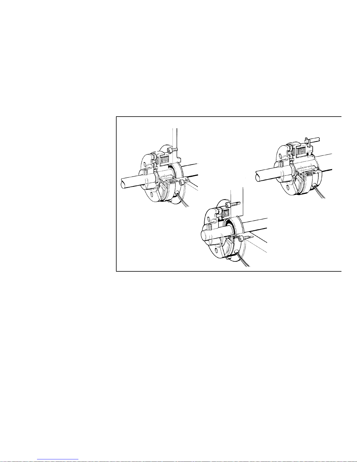
4.2.1 Clutch and brake of design 1
The stator of clutch or brake of design 1 must be mounted internally or externally centered
(observe dimension “tk” for max. centricity from Tab. 3). The mounting surface should not exceed
a maximum phase run-out “ x” (Tab. 3) and should not be convex. In the case of internal centring
the register diameter is machined to an oval clearance.
When the rotor is assembled, dimension “ b” (Tab. 3) must be observed maintained.
Stop!
The rotor must be secured axially!
Fig. 5 Internal centring External cent ring
4.2.2 Stator design 3
The stator design 3 does not need a mounting surface as the centring is performed by a deep
groove ball bearing on the rotor. A torque arm must be provided for the bearing fric tion. This
torque arm engages in the recess of the anti-rotation tag.
Stop!
The stator must not be strained in any case!
Page 16

Installation
16
i
BA 14.105/115 EN 2.0
4.2.3 Mounting of armature assembly of designs 1, 2 and 5
The armature assembly is shifted onto the shaft. The maximum permissible centre offset of the
shafts, dimension ” tw” can obtained from Tab. 3. The air gap “sLü” (Tab. 3) must be adjusted
using a feeler gauge.
Use shims for the exact air gap setting and for the compensation of wear.
Stop!
The armature assembly must be fixed axially.
14.105
14.115
Fig. 6
Size
s
Lü
x INTORQ 14.105 INTORQ 14.115
[mm] [mm] t
k
t
w
b [mm] t
w
b [mm]
06 0,2 ± 0.05 0.04 0.2 0.1 24 0.16 18
08 0,2 ±0.05 0.05 0.3 0.1 26.5 0.16 20
10 0,2 ±0.05 0.06 0.3 0.1 30 0.16 22
12 0.3 ± 0.1 0.07 0.3 0.1 33.5 0.2 24
16 0.3 ± 0.1 0.09 0.4 0.2 37.5 0.2 26
20 0.5 ± 0.15 0.11 0.4 0.2 44 0.2 30
25 0.5 ± 0.15 0.14 0.5 0.2 51 0.3 35
Ta b . 3
Page 17

Installation
17
i
BA 14.105/115 EN 2.0
4.2.4 Mounting of armature assembly of design 3
Use bolts with threads up to the head to fix the armature assembly.
•
For the tapped holes the clearance bores “ Ød” and the depth “t” (Tab. 4) must be observed
maintained in any case.
•
The rivet heads require a sufficient clearance hole.
Size Screws DIN Schnorr lock washer * Ø d [mm] t [mm]
06 M3x8 DIN 84 Schnorr lock washer 3 3.1 0.8
08 M4x10 DIN 84 Schnorr lock washer 4 4.1 1.0
10 M5x12 DIN 6912 Schnorr lock washer 5 5.1 3.5
12 M6x16 DIN 7984 Schnorr lock washer 6 6.1 2.8
16 M8x20 DIN 7984 Schnorr lock washer 8 8.2 3.5
20 M10x25 DIN 7984 Schnorr lock washer 10 10.2 3.5
25 M12x25 DIN 7984 Schnorr lock washer 12 12.2 3.8
Ta b . 4
1
2
3
4
5
1 Mounting surface
2Armatureplate
3Screw
4 Prestressed spring
5 Lock washer
d
t
Fig. 7
* Source of supply:
Adolf Schnorr GmbH & CO KG
Postfach 60 0162; D-71050 Sindelfingen
Phone: ++49 7031 - 3020; Fax: ++49 7031 - 382600
Page 18

Installation
18
i
BA 14.105/115 EN 2.0
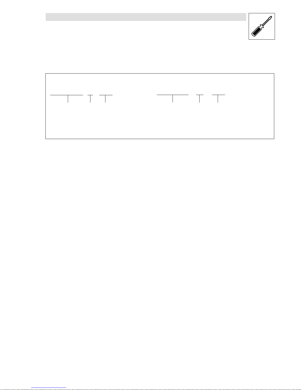
4.3 Electrical connection
The device is connected to DC voltage (observe voltage specific ation on the stator). Permissible
voltage fluctuation acc. to VDE 0580: +6% to -10%.
The standard voltage is 24 V DC. If no DC voltage is available the voltage must be supplied via
transformers or rectifiers.
The clutches and brakes should be switched on the DC side to achieve short switch-off times.
secondary
primary
230V ~ 50Hz
230V ~ 50Hz
Universal spark suppressor
14.198.00.01 ... 04
Fig. 8 Switching on the DC side Switching on the AC side
When switching on the DC side use a spark suppressor to protect coil and contacts from
excessive inductive voltages.
Stop!
If there is no protective circuit the induc tive voltage can be higher than the values specified in
VDE 0580 and cause the coil to fail which destroys switching contacts.
The spark suppressor consists of a non-inductive pulse capacitor which accepts current peaks
during switching. When a spark suppressor is used the spark at the contact and thus the contact
erosion is considerably reduced.
Page 19

Maintenance
19
i
BA 14.105/115 EN 2.0
5 Maintenance
The clutches and brakes are largely free of maintenanc e. In applications requiring many switching
operations the air gap “sLü” must be checked and readjusted at certain periods. When t he air gap
has reached 250% of its rated value “sLü” at the latest it must be readjusted to the rated value at
the latest.
•
For air gap setting “sLü” after wear see chapter 5.1, Disassembly.
•
The shims mentioned in section 2 can be removed or the spacers can be reduced.
The friction face poles of the rotor or stator of clutches or brakes run into the armature plate.
Friction marks are thus normal and must not be re-worked!
Stop!
Friction faces must be kept absolutely free of oil and grease!
5.1 Disassembly
Remove the axial circlip or shaft locking plate Fig. 9 to disassemble the armature assembly of
design1or2ortherotor.Afterthatthearmatureassemblycanbewithdrawnfromtheshaftvia
the withdrawal thread “d” (see Fig. 9 and Tab. 5) provided for disassembly in the flange hub or
rotor of the corresponding part. After the armature assembly has been withdrawn, remove the
shims depending on the air gap size “sLü” (Fig. 6 and Tab. 3) and mount them afterwards between
circlip and flange hub.
d
e
d
c
Fig. 9
Size
06 08 10 12 16 20 25
øc 29 36 46 56 73 92 114
d M4 M4 M4 M4 M5 M6 M8
øe 31 37 47 56 73 93 120
Ta b . 5 D i m e n s i o n s i n m m
Page 20

Maintenance
20
i
BA 14.105/115 EN 2.0
5.2 Spare parts list
The clutches and brakes have a wear reserve of several millimeters. When these are used up after
several readjustments the rotor and armature assembly of clutches and the stator and armature
assembly of brakes must be replaced in pairs.
•
When ordering spare parts indicate the designation of the parts according to the illustration
and list below.
3
1
2
10
5
67
11
12 11
14 13 15
4
5
10
86
Item Name Item Name
1 Clutch-stator design 1 10 Setscrew
2 Rotor design 1 11 Deep-groove ball bearing 2RS
3 Clutch - stator + rotor 12 Spacer
4 Brake - stator 14.115 13 Circlip
5 Armature assembly design 1 14 Fitted key
6 Armature assembly design 3 15 Spring ring
7 Armature assembly design 5
8 Armature assembly design 2
Page 21
Maintenance
21
i
BA 14.105/115 EN 2.0
•
Spare parts should be ordered according to the following example:
Electromagnetic clutch
Type Size Spare part
Electromagnetic brake
Type Size Spare part
INTORQ 14.105. 10. Item 1 - 24V / 28W INTORQ 14.115. 16. Item 6
•
When you order stators you also have to indicate the coil voltage and power (see section
Electrical connection).
•
When ordering rotors, armature assemblies of designs 1 and 2 also specify the bore diameter.
Page 22

Hersteller
Head Office
INTORQ GmbH & Co. KG
Postfach 1103
D-31849 Aerzen
Wülmser Weg 5
D-31855 Aerzen
Telefon +49(0)5154 / 9539-01
Te lefax +49 (0)5154 /95 39-10
E-mail: info@intorq.de
http://www.intorq.de
Kundendienst /Service
Lenze Drive Systems GmbH
Extertal-Bösingfeld
Breslauer Straße 3
D-32699 Extertal
Telefon +49(0)5154 / 82-1215
Telefax +49 (0)5154/ 82-11 12
Der Vertrieb erfolgt über die
Lenze-Vertriebsorganisation
Sales are organized by
Lenze’s sales department
Deutschland
Germany
Lenze Vertrieb GmbH
Ludwig-Erhard-Straße 52-56
D-72760 Reutlingen
Telefon +49 (0)71 21 /9 3939-0
Telefax +49 (0)7121 / 9 3939-29
Region Nord
Dornenpark 1
31840 Hessisch Oldendorf
Telefon (051 52) 90 36-0
Telefax (0 51 52) 9036-33/44/55
Region West
Postfach 10 12 20
47497 Neukirchen-Vluyn
Kelvinstraße 7
47506 Neukirchen-Vluyn
Telefon (028 45) 95 93-0
Telefax (0 28 45) 9593 93
Region Mitte/Ost
Postfach 1463
35724 Herborn
Austraße 81
35745 Herborn
Telefon (027 72) 95 94-0
Telefax (0 27 72) 530 79
Region Südwest
Postfach 14 33
71304 Waiblingen
Schänzle 8
71332 Waiblingen
Telefon (071 51) 9 59 81 - 0
Telefax (0 71 51) 959 8150
Region Süd
Fraunhoferstraße 16
82152 Martinsried
Telefon (089) 89 56 14-0
Telefax (0 89) 89 5614 14
weltweit
worldwide
ALGERIA
see FRANCE
ARGENTINA
E.R.H.S.A.
Girardot 1368
1427 BUENOS AIRES
Phone +54 (0)11 / 45 54 32 32
Telefax +54 (0)11 / 45 52 3611
AUSTRALIA
FCR Motion Technology Pty. Ltd.
Unit 6, Automation Place
38-40 Little Boundary Rd.
Leverton North
3026 MELBOURNE, VIC.
Phone +61 (03) 9362 6800
Telefax +61 (03) 9314 3744
AUSTRIA
Lenze Antriebstechnik GmbH
Ipf-Landesstraße 1
4481 ASTEN
Phone +43 (0)7224 / 21 0-0
Telefax +43 (0)7224 / 2109 99
Office Dornbirn:
Lustenauer Straße 64
6850 DORNBIRN
Phone +43 (0)5572 / 26 789-0
Telefax +43 (0)5572 / 26 789-66
Office Wr. Neudorf:
Triester Straße 14/109
2351 WR. NEUDORF
Phone +43 (0)2236 / 2 5333-0
Telefax +43 (0)2236 / 2 53 33-66
Office Graz:
Seering 8
8141 UNTERPREMSTÄTTEN
Phone +43 (0)3135 / 56 900-0
Telefax +43 (0)3135 / 56 900 999
Lenze Verbindungstechnik GmbH
Ipf-Landesstraße 1
4481 ASTEN
Phone +43 (0)7224 / 21 1-0
Telefax +43 (0)7224 / 2119 98
Lenze Anlagentechnik GmbH
Mühlenstraße 3
4470 ENNS
Phone +43 (0)7223 / 886-0
Telefax +43 (0)7223 / 886-997
BELGIUM
Lenze b.v.b.a
Noorderlaan 133, bus 15
2030 ANTWERPEN
Phone +32 (0)3 / 54 26 20 0
Telefax +32 (0)3 / 54 13 75 4
BOSNIA-HERZEGOVINA
see AUSTRIA
BRAZIL
AC Control Ltda
Rua Gustavo da Silveira 1199
Vila Sta. Catarina
SÃO PAULO – S.P.
04376-000
Phone +55 (11) 55 64 65 79 ramal: 214
Telefax +55 (11) 56 79 75 10
BULGARIA
see MACEDONIA
CANADA
see USA
CHILE
Sargent S.A.
Tecnica Thomas C. Sargent
S.A.C.é.l., Casilla 166-D
SANTIAGO DE CHILE
Phone +56 (0)2 / 51 03 000
Telefax +56 (0)2 / 69 83 989
CHINA
Lenze Mechatronic Drives (Shanghai)
Co. Ltd., Section B, 50# building,
No.199 North Ri Ying Road,
Waigaoqiao Free Trade Zone
SHANGHAI, 200131
Phone +86-21-5046 0848
Telefax +86-21-5046 0850
Beijing Office
Rm. 401, Huaxin Mansion
No. 33 An Ding Road, Chaoyang District
BEIJING 100029
Phone +86-10-6441 1470
Telefax +86-10-6441 1467
CROATIA
Lenze Antriebstechnik GmbH
Predstavnista Zagreb
Ulica Grada Gospica 3
HR-1000 ZAGREB
Phone +385-1-2 49 8056
Telefax +385-1-2 4980 57
CZECH REPUBLIC
Lenze, s.r.o.
Central Trade Park D1
396 01 HUMPOLEC
Phone +420 565 507-111
Telefax +420 565 507-399
Büro âerven˘ Kostelec:
17. listopadu 510
549 41 âERVEN¯ KOSTELEC
Phone +420 491 467-111
Telefax +420 491 467-166
DENMARK
Lenze A/S
Vallensbækvej 18A,
2605 BRØNDBY
Phone +45 / 46 96 66 66
Telefax +45 / 46 96 6660
24 stunde service +45 / 40 9304 11
Buero Jylland:
Lenze A/S, Enebærvej 11
8653 THEM
Phone +45 / 46 96 66 66
Telefax +45 / 46 96 6680
EGYPT
WADI Co. for technologies
and development
P. O.Box 209, new center Ramses
11794 CAIRO, Egypt
11 Syria St., Mohandessin
GIZA, Egypt
Phone +20 (2) 347 6842
Telefax +20 (2) 347 6843
ESTONIA
see FINLAND
FINLAND
Lenze Drives
Rykmentintie 2 b, 20810 TURKU
Phone +358 2 2748180
Telefax +358 22748 189
FRANCE
Lenze S.A.
Siege
Z.A. de Chanteloup
Rue Albert Einstein
93603 AULNAY-SOUS-BOIS CEDEX
Services Commerciaux
Tel. 0825 086036
Fax 0 825 086 346
Centre de formation
E-Mail : semin.sidonie@lenze.fr
Questions générales / Documentation
E-Mail : info@lenze.fr
Service Après-vente /
assistance en ligne
Helpline 24/24 : 0 825 826 117
E-Mail:helpline@lenze.fr
Agences en France
Région France Nord :
Z.A. de Chanteloup
Rue Albert Einstein
93603 AULNAY-SOUS-BOIS CEDEX
Lille
59420 MOUVAUX
Strasbourg
67960 ENTZHEIM
Rouen
76500 ELBEUF
INTORQ – sales and service worldwide
Page 23

Région France Sud :
Rond point du sans souci
69578 LIMONEST Cedex
Toulouse
31400 TOULOUSE
Agen
47270 SAINT-PIERRE DE CLAIRAC
GREECE
George P. Alexandris S.A.
12K. Mavromichali Str.
185 45 PIRAEUS
Phone +30 (0)210 /41 1184 15
Telefax +30 (0)210/ 4 11 81 71
4127058
183 Monastiriou Str.
546 27 THESSALONIKI
Phone +30 (0)310 /5 5665 04
Telefax +30 (0)310/ 51 18 15
HUNGARY
Lenze Antriebstechnik
Handelsgesellschaft mbH
2040 BUDAÖRS
Gyár utca 2., P.O.Box 322.
Phone +36 (0)23 / 501-320
Telefax +36 (0)23 / 501-339
ICELAND
see DENMARK
INDIA
Electronic Service:
National Power Systems,
10, Saibaba Shopping Centre
Keshav Rao Kadam Marg,
Off Lamington Rd,
MUMBAI 400 008
Phone +91 22 / 2300 5667, 2301 3712
Telefax +91 22/ 2300 5668
V3 Controls Pvt. Ltd.
1, “Devyani”, Next to SBI,
Baner ITI Road, Sanewadi, Aundh,
PUNE 411 007, MS
Phone +91 20 /25 8868 62
Telefax +91 20/ 25 88 0350
Mechanical Service:
Emco Lenze Pvt. Ltd.
1st Floor, Sita Mauli
Madanlal Dhingra Road
Panch Pakhadi, Thane (West)
MAHARASHATRA 400602
Phone +91 22 /25 4054 88
+91 22/ 25452244
Telefax +91 22/ 25 45 2233
INDONESIA
P. T. Futurindo Globalsatya
Jl.: Prof. Dr. Latumenten No. 18
Kompleks Perkantoran
Kota Grogol Permai Blok A 35
JAKARTA 11460
Buero 1:
Phone +62 (0)21 /766 42 34
765 8623
Telefax +62 (0)21 / 766 4420
Buero 2:
Phone +62 (0)21 /567 96 31
567 9632
Telefax +62 (0)21 / 566 8750
IRAN
Tavan Ressan Co. Ltd.
P.O.Box. 19395-5177
No. 44, Habibi St.,
South Dastour St.,
Sadr EXP’Way,
TEHRAN 19396
Phone +98 21 / 260 2655
260 6766
260 9299
Telefax +98 21 / 200 28 83
ISRAEL
Greenshpon Engineering Works LTD
Bar-Lev Industrial Park
MISGAV 20179
Phone +972 4 99 13 18 1
Telefax +972 4 99 13 477
ITALY
Gerit Trasmissioni S.p.A.
Viale Monza 338, 20128 MILANO
Phone +39 02 / 270 98.1
Telefax +39 02 / 270 98 290
JAPAN
Miki Pulley Co., Ltd.
1-39-7 Komatsubara, Zama-c
ity
KANAGAWA 228-8577
Phone +81 (0)462 / 58 16 61
Telefax +81 (0)462 / 5817 04
LATVIA
see LITHUANIA
LITHUANIA
Lenze UAB
Breslaujos g.3, 44403 KAUNAS
Phone + 370 37 407174
Telefax +370 37 407175
LUXEMBOURG
see BELGIUM
MACEDONIA
Lenze Antriebstechnik GmbH
Pretstavnistvo Skopje
ul. Nikola Rusinski 3/A/2
1000 SKOPJE
Phone +389 2 30 90 090
Telefax +389 2 30 90091
MALAYSIA
D.S.C. Engineering SDN BHD
3A & 3B, Jalan SS21/56B
Damansara Utama
47400, PETALING JAYA
SELANGOR
Phone +60 (0)3 / 77 2562 43
77 2562 46
77 2865 30
Telefax +60 (0)3 / 77 29 5031
MAURITIUS
Automation & Controls Engineering Ltd
3, Royal Road
Le Hochet, Terre Rouge
MAURITIUS
Phone +230 248 8211
Telefax +230 248 8968
MEXICO
Automatización y Control
de Energía S.A. de C.V.
Av. 2 No. 89 Esq Calle 13
Col. San Pedro de los Pinos
C.P. 03800 MEXICO D.F.
Phone +52 (55)5277/5998
Telefax +52 (55)5277/5937
MOROCCO
GUORFET G.T.D.R
Automatisation Industrielle
Bd Chefchaouni Route 110 km, 11.500
No. 353-Aîn-Sabaâ
CASABLANCA
Phone +212/22-35 7078
Telefax +212/22-35 7104
NETHERLANDS
Lenze B.V., Postbus 31 01
5203 DC`S-HERTOGENBOSCH
Ploegweg 15
5232 BR`S-HERTOGENBOSCH
Phone +31 (0)73 / 64 56 50 0
Telefax +31 (0)73 / 64 56 51 0
NEW ZEALAND
Tranz Corporation
343 Church Street
P. O. Box 12-320, Penrose
AUCKLAND
Phone +64 (0)9 / 63 45 51 1
Telefax +64 (0)9 / 63 45 51 8
NORWAY
Dtc- Lenze as
Stallbakken 5, 2005 RAELINGEN
Phone +47 / 64 80 25 10
Telefax +47 / 64 80 25 11
PHILIPPINES
Jupp & Company Inc.
Unit 224 Cityland Pioneer Bldg.,
Pioneer Street
MANDALUYONG CITY
Phone +63 2 /687 7423
683 0042
683 0047
Telefax +63 2 / 6877421
POLAND
Lenze-Rotiw Sp. z o.o.
ul. Ro˝dzieƒskiego 188b
40-203 KATOWICE
Phone +48 (0)32 / 2 03 97 73
Telefax +48 (0)32 / 7 81 0180
Lenze Systemy Automatyki Sp. z o.o.
Ul. Rydygiera 47
87-100 TORU¡
Phone +48 (0)56 / 6 58 28 00
6453460
6453570
Telefax +48 (0)56 / 6 45 3356
PORTUGAL
Costa Leal el Victor
Electronica-Pneumatica, Lda.
Rua Prof. Augusto Lessa, 269,
Apart. 52053
4202-801 PORTO
Phone +351-22 / 550 8520
Telefax +351-22 /5 02 40 05
ROMANIA
see AUSTRIA
RUSSIA
Inteldrive
1 Buhvostova Street 12/11
Korpus 18, Office 322
MOSCOW 107258
Phone +7 (0)095 / 963 96 86
Telefax +7 (0)095 / 962 67 94
SERBIA-MONTENEGRO
see MACEDONIA
SINGAPORE
see MALAYSIA
SLOVAC REPUBLIC
ECS Sluzby spol. s.r.o.
Staromlynska 29
82106 BRATISLAVA
Phone +421 2 45 25 96 06
+421 2 45 64 31 47
+421 2 45 64 31 48
Telefax +421 2 45 64 3149
SLOVENIA
Lenze pogonska tehnika GmbH
Zbiljska Cesta 4
1215 MEDVODE
Phone +386 (0)1 361 61 41
Telefax +386 (0)1 361 2288
SOUTH AFRICA
S.A. Power Services (Pty.) Ltd.
Unit 14, Meadowbrook Business Estates
Jacaranda Ave, Olivedale, Randburg 2158
P. O.Box 1137, RANDBURG 2125
Phone +27(11) 462-8810
Telefax +27(11) 704-5775
SOUTH KOREA
Hankuk Mechatro Ltd.
Room# 1409 Samhwan officetel 830-295
Beomil-dong, Dong-Gu
PUSAN
Phone +82 (0)51-635-6663
Telefax +82 (0)51-635-6632
SPAIN
Lenze Transmisiones, S.A.
Mila i Fontanals, 135-139
08205 SABADELL (Barcelona)
Phone +34 93 / 72 07 68 0
Telefax +34 93 / 71 22 54 1
SWEDEN
Lenze Transmissioner AB
P.O.Box 10 74, Attorpsgatan
Tor nby Ind.
58110 LINKÖPING
Phone +46 (0)13 / 35 5800
Telefax+46 (0)13 / 10 36 23
SWITZERLAND
Lenze Bachofen AG
Ackerstrasse 45
8610 USTER
Phone +41 (0) 43 399 1414
Telefax+41 (0) 43 399 14 24
Vente Suisse Romande:
Route de Prilly 25
1023 CRISSIER
Phone +41 (0)21 / 63 72 19 0
Telefax +41 (0)21 / 63 72 19 9
SYRIA
Zahabi Co.
8/5 Shouhadaa Street
P. O . Box 8262
ALEPPO-SYRIA
Phone +963 21 21 22 23 5
Telefax +963 21 2122 237
TAIWAN
ACE Pillar Co. Ltd.
No.12, Lane 61, Sec. 1,
Kuanfu Road, San-Chung City
TAI PEI HSIEN
Phone +886 (0)2 / 299 58 40 0
Telefax +886 (0)2 / 299 53 46 6
THAILAND
PSG-WESCO CO., LTD.
429 Moo 7, Theparak Road,
Tambol Theparak
Amphur Muang
SAMUTPRAKARN 10270
Phone +66 (0)2 / 383 5633
Telefax +66 (0)2 / 3835637
TUNESIA
AMF Industrielle Sarl
Route de Gremda - Km 0,2
Immeuble El Madina,
Centre Bloc B - 5 ème - appt 52
3002 SFAX
Phone +216 74 403514
Telefax +216 74402 516
TURKEY
LSE Elektrik
Elektronik Makina, Otomasyon Mühendislik
San. Ve Tic. Ltd. Ωti.
Atatürk mah. Cumhuriyet cad.
Yurt sok. No:7
ÜMRANIYE /∑STANBUL
Phone +90 (0)216 / 316 5138 pbx
Telefax +90 (0)216 / 443 4277
Bursa Address:
Demirtaspasa Mh.
Ata Sk. Petek Bozkaya Is Merkezi
D Blok No :5 / A
OSMANGAZI / BURSA
Phone +90 (0)224-2733232 pbx
+90 (0)224-2734151
+90 (0)224-2733238
Telefax +90 (0)224-2734150
UKRAINE
SV Altera Ltd.
Ivana Lepse ave, 4
KIEV, 03067
Phone +38-044 496 1888
Telefax +38-044 496 18 18
UNITED KINGDOM/EIRE
Lenze Ltd.
Caxton Road
BEDFORD MK 41 OHT
Phone +44 (0)1234 / 32 13 21
Telefax +44 (0)1234 / 26 18 15
USA
AC Technology Corp.
630 Douglas Street
UXBRIDGE, MA 01569
Phone +1 508 /278-9100
Telefax +1 508/ 278-7873
Lenze Corporation
1730 East Logan Avenue
EMPORIA, KS 66 801
Phone +1 620 /343-8401
+1 888/ 269-2381
Telefax +1 620/ 342-2595
+1 800/ 469-0931
INTORQ – sales and service worldwide
Page 24

INTORQ GmbH & Co. KG
Postfach 1103
D-31849 Aerzen
Wülmser Weg 5
D-31855 Aerzen
Tel.: +49 (0) 5154 / 95 39- 01
Fax.: +49 (0) 5154 / 95 39-10
E-Mail: inf o@intorq.de
www.intorq.de
 Loading...