

t:00359 898 606 796 ||| f:00359 596 325 80 ||| info@intiel.com ||| www.intiel.com
9 Peter Beron Str, Pomorie 8000, Bulgaria
- 1 -
INTIEL
THE ELECTRONICS ON YOUR SIDE
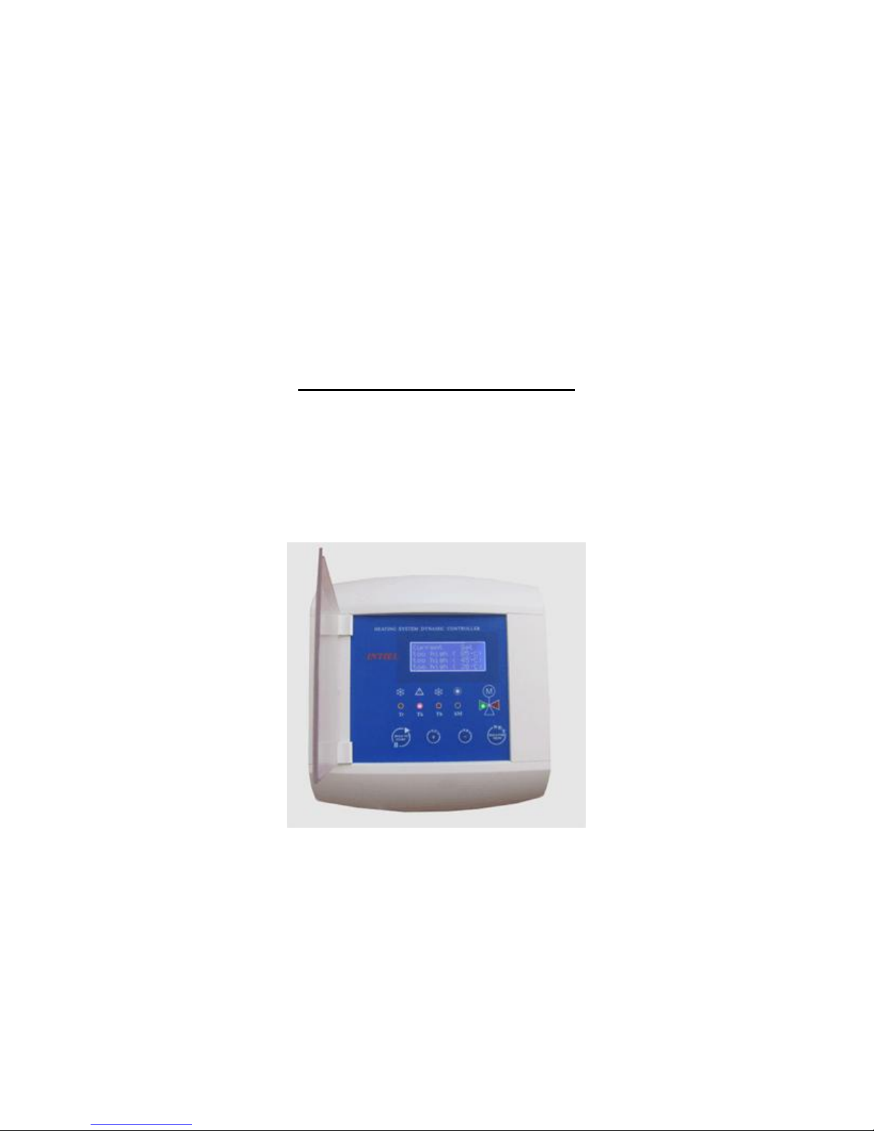
Dynamic Boiler Controller
User’s Manual

t:00359 898 606 796 ||| f:00359 596 325 80 ||| info@intiel.com ||| www.intiel.com
9 Peter Beron Str, Pomorie 8000, Bulgaria
- 2 -
Application
The Dynamic Boiler Controller is very suitable for water heating installations in
family houses, small and large projects. It is designed to provide the desired heating comfort,
optimizing the fuel consumption by a control of the boiler operation. In fact it is able to
manage the operation of solid fuel, light fuel and gas boilers and as well the consumption of a
heating energy from accumulating reservoirs or other central heating sources.
The traditional heating controllers regulate the temperature of the water system in
relation to the ambient temperature. Compare with them, the Dynamic Boiler Controller can
manage the regulation processes by the real boiler temperature. If a right estimation of the
internal water temperature is available, the heating system will react to additional heating
sources like sun shine, people presence in the premises, working machines and so on.
The principle of dynamic regulation is that the Controller follows the room thermostat,
measures the temperature of the heating water in the heating circuit and the temperature in the
small boiler circuit and bases on all that data, regulates the position of the four-way mixed
valve and thus controls the boiler operation. The central heating systems equipped with a
four-way mixed valve provides protection against low temperature corrosion of the boiler
body. In this way the setting-up of the heating curve (something usual for an equithermal
regulation) with all negative consequences of the regulation is not necessary.
The Controller provides a domestic hot water preparation in the accumulating water
heater, which is being managed by the domestic hot water thermostat, installed in the water
heater (or in the accumulating reservoir), where also can be added a timer-switch. The
Controller provides the heating of the domestic hot water with same or higher priority
compare to the heating of the premises. The type of priority can be adjusted in compliance
with customer’s preferences.
1. Controller description
Basically the Controller can operate in two configurations as a dynamic regulator with
connected room thermostat and as an equi-thermal regulator without a room thermostat.
1.1 Main functions:
1.1.1 Measure the water temperature at three points: outlet boiler temperature (sensor K),
return boiler water (small boiler circuit sensor V) and the heating water (in the heating
circuit) after a mixed valve (sensor O).
1.1.2 Measure the outdoor temperature (sensor A)
1.1.3 Measure the room temperature by room thermostats with a contact output (RT)
1.1.4 Stops the boiler operation by a signal of the built-in operation boiler thermostat, when
the maximum working temperature exceeds (+750C)-(+900C) (sensor K).
1.1.5 Opens the mixed valve, switch on the circulation pump and switches off the boiler if
the outlet boiler temperature (sensor K) exceeds its emergency level of (+850C)-
(+1050C)
1.1.6 Closes the mixed valve and starts the boiler by force (only in a winter mode) if the
return boiler water temperature (sensor V) is lower than the settled one of (+250C)-
(+650C).
1.1.7 Open the mixed four-way valve and start by force the boiler operation if the water
temperature after the mixed valve in the heating circuit (sensor O) is lower than the
calculated one Thset. The operation threshold is changing automatically by the
outdoor temperature of the installed outdoor thermostat (A). If a room thermostat is
not mounted this function can be used for a central equi-thermal temperature
regulation of the water heating in multi-circuit and large systems.

t:00359 898 606 796 ||| f:00359 596 325 80 ||| info@intiel.com ||| www.intiel.com
9 Peter Beron Str, Pomorie 8000, Bulgaria
- 3 -
1.1.8 Protection against freezing of the whole heating system.
1.1.9 Closes by force the mixed valve in systems equipped with a room thermostat, despite
of its command in case the heating water exceeds its maximum assignation.
1.1.10 Controls the mixed valve in relation to the room thermostat. The room thermostat
option can be switched off, for example concerning large and multi-circuits systems.
1.1.11 Provides a domestic hot water preparation in a winter and a summer mode in relation
to the domestic hot water thermostat or timer.
1.1.12 Possibility for adjusting a priority, concerning domestic hot water preparation:
Same one with the heating of the premises or
Higher one by stopping the premises heating.
The customer is to adjust one of those two priorities.
1.1.13 Control a circulation pump, an actuator or a magnetic valve in the domestic hot water
circuit.
1.1.14 Automatically goes into a summer mode if the room thermostat or the sensor after the
mixed valve (“O”) does not send a command for a start in a period adjusted by the
customer of 12, 24, 36 or 48 hours after the last command is being sent.
1.1.15 The main distinguish of the summer mode is that the boiler cannot be started if the
return water temperature of the boiler is lower than the settled one Tkset, as circulation
pumps P1 and P2 are switched off.
1.1.16 Automatically goes into a winter mode if a command of the room thermostat is
available or if the heating water temperature (measured by sensor O) is lower than
Thset.
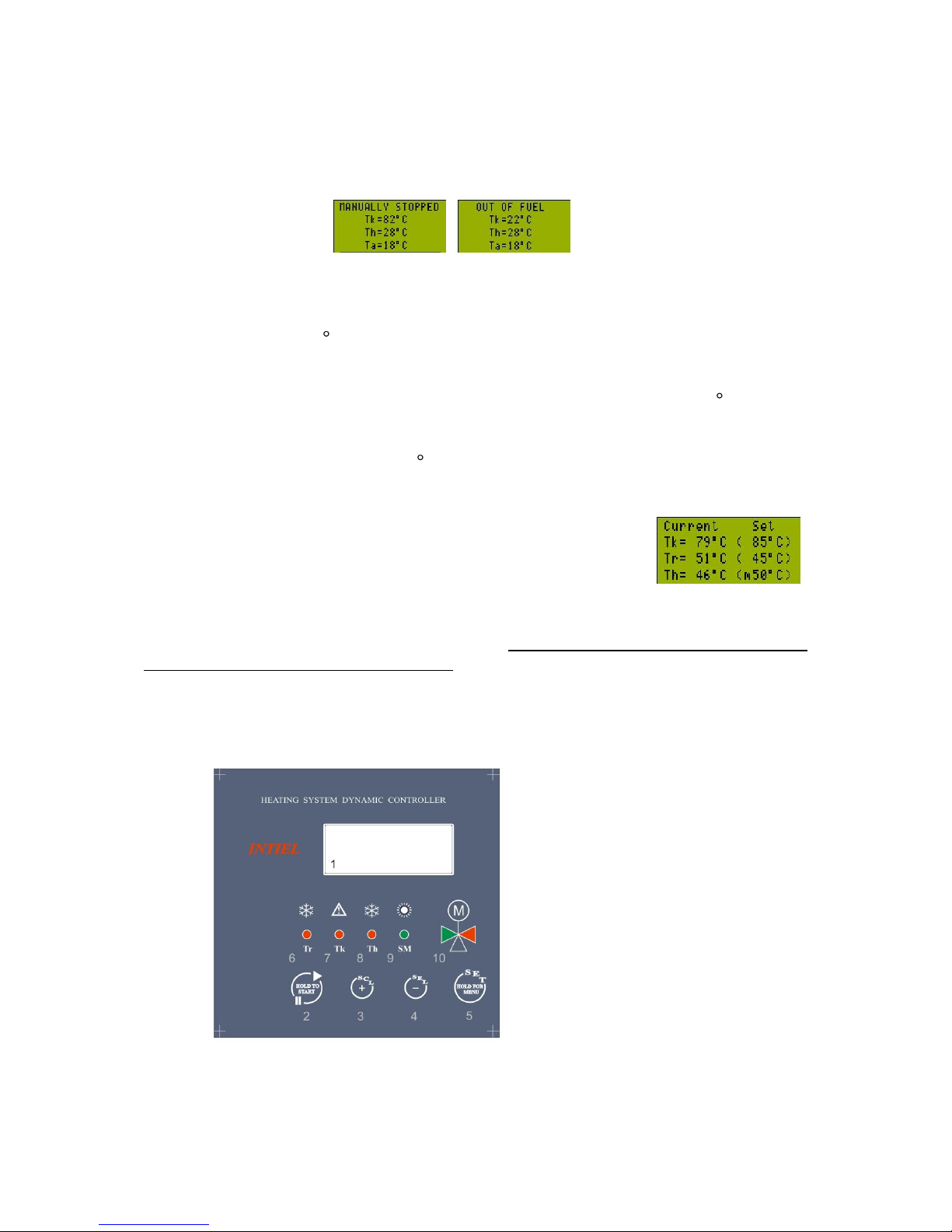
1.1.17 STOP mode can be fulfilled by the controller in two ways: automatically with the fuel
run out or manual, indication about which appears on the display (fig.2) . Going back to the
previous mode is to be done only manually.
1.1.18 Periodically starting the circulation pump in the heating circuit and the mixed valve
during summer and STOP mode in order to prevent their blocking after a long stop.
1.1.19 Manual assignation of the heating water temperature.
1.1.20 Timer and a weekly programmer for an economic operation programming.
On figure 1 is shown functional heating systems, managed by the controller.
Figure 1
K
М
SV
P2
O
RТ
Boiler
Controller
Start
Stop
P1
А
Water
Heater
P3
V

t:00359 898 606 796 ||| f:00359 596 325 80 ||| info@intiel.com ||| www.intiel.com
9 Peter Beron Str, Pomorie 8000, Bulgaria
- 4 -
1.2 Operation modes
1.2.1 Winter mode
The Controller automatically fix a winter mode in terms of switching on its power
supply. Then it is is able to goes into winter mode and to start the boiler only by two ways:
signal by a room thermostat or heating water temperature (measured with sensor O) lower
than Thset.
During that mode the Dynamic Boiler Controller manages with priority the temperatures at
above mentioned points 1.1.5 and 1.1.6. The control of the minimal temperature level of the
heating water according point 1.1.7 is of an importance if the heating system temperature falls
down bellow the adjusted one (for example at the programmable night drops). In fact, that
provides the optimum heating comfort in the building and quicker heating after switching
from economical to a comfort room temperature level. This function is very useful for
systems with a grate water contents and inertness. The regulated minimal temperature level of
the heating water is either permanent or controlled by the room temperature.
The desired room temperature is kept in compliance with the room thermostat
measurement and the Dynamic Boiler Controller manages the heating water temperature in
accordance with that temperature. The Controller reacts to the time of switching (ON/OFF) of
the room thermostat and thus the best results can be achieved by using proportional
thermostat with an integration control of the temperature. The precision class of the used
room thermostat directly affects to the precision in keeping the desired room temperature
level.
1.2.2 Summer mode
The transition to summer mode can be done automatically if the room thermostat or
sensor “O” does not send a command for starting in 12 hours (the adjustment can be done
within 12-48 hours) after the last stopping. That stop interval is to be fixed at menu
“OTHERS”. During the transition to a summer mode the Controller performs the following:
Stops the circulation pumps P1 and P2.
Stops the boiler.
Closes the mixed valve.
The Controller provides regular tests of the circulation pumps P1 and P2 and the
mixed valve in order to avoid the fur accumulating at the heating system mobile parts. The
first step of that test is the start of the circulation pumps and their subsequent stopping. The
next one is the opening and closing of the mixed valve. This prevents the hot water
penetration from the boiler circuit to the heating one during a summer mode.
The domestic hot water preparation during the summer is performed at a closed mixed
valve and a stopped circulation pump P2. The boiler starts operation by switching on the
domestic hot water thermostat or by a timer switch, connected to the domestic hot water
terminals of the Controller. In this way the boiler is being switched on if it is necessary,
keeping summer mode settings. In this mode as well, the boiler is being kept against
emergency overheating of the outlet boiler water or overcooling of the return one.
t:00359 898 606 796 ||| f:00359 596 325 80 ||| info@intiel.com ||| www.intiel.com
9 Peter Beron Str, Pomorie 8000, Bulgaria
- 5 -
1.2.3. Stop mode
STOP mode is being fixed automatically in case of fuel finish or manual (indication
about which is being shown on the display figure2), as again it is being performed stopping of
the circulation pumps, boiler and mixed valve closing.
STOP mode can be entered manual if button “stop” on the front panel is being pressed.
The controller goes automatically into STOP mode in case of fuel finish with gas, light oil or
solid fuel boilers (Tk<40 С for more than 30min.). Escaping STOP mode is able to be done
only manual by means of keeping pressed button “stop” as the Controller fix the previous
mode. During STOP mode is being observed only heating water, outlet boiler water and the
outdoor temperature. In case of very low heating water temperature (bellow 5 С) and fuel
presence, the boiler and pumps are being switched on as the valve starts opening in order to
prevent freezing (light indication 8 is being activated, figure3a). The previous goes on until
the heating water temperature reach 10 С.
1.2.4. Manual mode
In this mode the heating water assignation can be defined manually.
Mode settings and start are to be done in submenu “MANUAL
REGIME”. In case this mode is started a letter “m” appears in the
brackets where the temperature of the heating water is being indicated.
Returning to the previous mode is able to be done manually in the relevant submenu, or
automatically if the calculated temperature of the heating water in relation to the outdoor
temperature exceeds the manual assigned one. The Manual mode cannot be started if a
room thermostat operation is being selected.
1.3 Controller basic elements
A general view of the Controller is shown at Figure 3, the Controller front panel at
Figure 3a and the Controller main board at Figure 3b.
Figure 3a
t:00359 898 606 796 ||| f:00359 596 325 80 ||| info@intiel.com ||| www.intiel.com
9 Peter Beron Str, Pomorie 8000, Bulgaria
- 6 -
Legend:
1. 4-raw digital LCD display
2. enter/escape button for STOP mode, used as well for allowing or prohibiting
the operation of the weekly programmer.
3. “+”(SCL) button, for forward navigation in the menu, as well for increasing of
the relevant value.
4. “-”(SEL) button, for forward navigation in the menu, as well for decreasing of
the relevant value.
5. SET button for a value confirmation and entering the main menu.
6. Indication for return temperature water decreasing, bellow the assigned value;
7. Control indication, showing exceeded emergency outlet boiler temperature.
8. Control indication, showing very low heating water temperature.
9. Summer mode indication.
10. Control indication, showing motor valve opening (>) and closing (<).
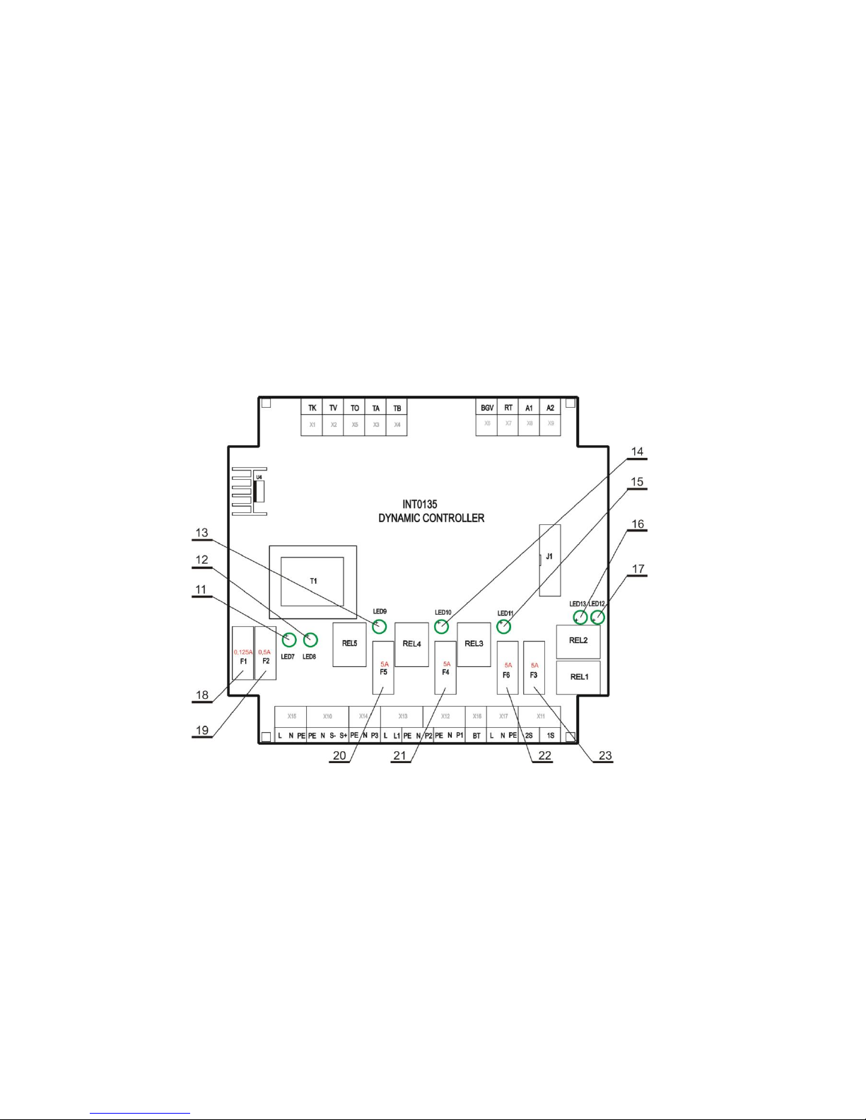
Figure 3.b
Legend
11. Service indication for motor valve closing
12. Service indication for motor valve opening
13. Service indication for switched on circulation pump 1
14. Service indication for switched on circulation pump 2
15. Service indication for switched on pump or motor actuator in the domestic hot water
circuit.
16. Service indication for 1st stage of the burner
17. Service indication for 2nd stage of the burner
t:00359 898 606 796 ||| f:00359 596 325 80 ||| info@intiel.com ||| www.intiel.com
9 Peter Beron Str, Pomorie 8000, Bulgaria
- 7 -
18 Fuse F1 – 0.125A about the controller electronic part
19. Fuse F2 – 0.5A about the motor actuator
20. Fuse F5 – 5A at the domestic hot water preparation output
21. Fuse F4 – 5A about circulation pump 2 in the heating circuit
22. Fuse F6 – 5A about circulation pump 1 in the small boiler circuit
23. Fuse F3 – 5A about burner power supply
1.4. Menus and settings
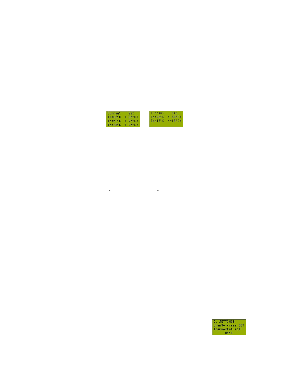
While the Controller is being set in one of the modes (summer, winter) on the display
are being indicated the current temperatures measured by the sensors, as well the adjusted
ones. By means of pressing “+”(SCL) button the following temperature groups are being
indicated.
Tk – current outlet boiler temperature, in brackets – the assigned temperature of the operation
thermostat about 1st stage of the burner.
Tr – current return boiler temperature, in brackets – the assigned one
Th – current heating water temperature measured after the mixed valve, in brackets – the
calculated one, or manual assigned one (m)
Tb – current water tank temperature, in brackets – the assigned one.
Ta – current outdoor temperature, in brackets – the assigned value at which the heating water
temperature has a maximum value Tou.min. (see point 1.5.5.1)
With temperatures below (20) С and above (+120) С, instead of values are being indicated
low and hi.
To enter the main menu button SET is to be pressed and kept for more than 3 sec., The Main
menu consists of four submenus, Manual Regime, Settings, Options and Other, which review
is able to be done by means of “+”(SCL) and “-” (SEL), as the selection by means of SEL
button.
Subnemu MANUAL REGIME:
- Define Thset – assignation of desired temperature of the heating water;
- Start and exit (Stор and exit) – start (stop) manual mode, escape directly to operation
mode.
Submenu SETTINGS
- Set limit Tk – setting the emergency value of the outlet boiler temperature
- Set return Tr – setting the return boiler temperature
- Heat min. Thmin – setting the lower border of the heating water temperature
- Heat max. Thmax – setting the upper border of the heating water temperature
- Set boiler Tb – setting the water tank temperature assignation
- Thermostat st1 – setting the operation thermostat 1st stage of the burner
- Thermostat st2 – setting the operation thermostat 2nd stage of the burner
Button SET is to be pressed in order to make some changes, as the value
starts blinking. Now the function of buttons “+”(SCL) and “-” (SEL) are
being changed to increasing and decreasing of the values. Once the desired
value is being selected then it has to be confirmed by means of SET button.

t:00359 898 606 796 ||| f:00359 596 325 80 ||| info@intiel.com ||| www.intiel.com
9 Peter Beron Str, Pomorie 8000, Bulgaria
- 8 -
Submenu OPTIONS
- Actuator speed - define the actuator speed (see point 3.1.7)
- Equi-thermal reg – selection of the lower border of the range about the
equithermal regulation. (Tout.min.)
- Night drop set – the value with which Thset drops during economic mode.
- Room thermostat – define if a room thermostat will be used. The setting come in
force after Controller switching on; In case of using a room thermostat Thmax is
being automatically limited up to 50 С if the room thermostat does not send a
signal for boiler starting.
- Boiler priority – defines whether the water tank is to be heated with an equal or
higher priority.
Press SET button in order to make some changes. By means of “+” button
it is able to go to the next option or by means of “-” to the previous one.
Submenu OTHER
- Summer regime – define the time within which if there is no signal from the room
thermostat or temperature sensor O, then the controller will automatically goes into
summer mode. It can be fixed within 12 – 48 hours;
- Kotel Type – define the boiler type, as boilers with gas and light oil (gas/liquid),
solid fuel boilers without their own controller (solid fuel 1) and solid fuel boilers
with their own controller (solid fuel 2), come in force after Controller switching
on;
- Restore settings – restore the default settings;
- Test actuator – it is being used for a control of correct wiring connection of the
actuator.
Press SET button in order to make some changes. By means of “+” button
it is able to go to the next option or by means of “-” to the previous one.
1.4.1. Weekly programmer – settings
The Controller is equipped with a built-in timer and a weekly programmer, for
programming of the night drops (economic mode) during which the calculated assignation of
the heating water drops with 5÷15 С. There could be assigned two time periods, which are to
be active during the whole week, during working or during weekend days (Saturday and
Sunday). By means of pressing SEL button (while on the display are being indicated the
current temperatures) it is being entered in timer and weekly programmer
menu, as escaping that menu can be done again with SEL button. On the
display are being indicated current date, hour, day of the week, as well the
status of the weekly programmer.
Status: stopped – weekly programmer function is prohibited;
Status: auto – the function is allowed, except in the case when about the two time
periods there are no selected days in the week, in which they are to be active.
The correction of date and time is to be done by means of pressing SET button, as
the status changing by means of “stop” button (button 2 of figure 3a).
Setting the time periods
By means of pressing SCL button, shows on the display the setting of the first time
period. There are no assigned time periods when the controller is primary started (a new one).

t:00359 898 606 796 ||| f:00359 596 325 80 ||| info@intiel.com ||| www.intiel.com
9 Peter Beron Str, Pomorie 8000, Bulgaria
- 9 -
Pressing SET button is to fix the hour and minutes for start and
stop. The values starts blinking as the change could be done by means of
SEL and SCL buttons, as the confirmation of the selected value can be done
by means of SET button. The next step is to select the days during which
the time period is to be active (whole week, working days, weekend). In
case no one day is selected means the time period is not active.
Button SCL is to be pressed in order to move to the second time
period. The setting about it is to be done in the same way. The settings will
be saved in the energy independent memory of the Controller, after pressing
SCL button again. To escape that menu SEL button is to be pressed.
If there is an active time period and the economic mode has been
modified the assignation of the heating water, then in the upper right corner
on the display a down arrow will appear.
The Controller is able to get back from any menu to regular operation status if no one
button is being pressed in 30 seconds time after the last used one.
1.5 Description of the sensors
The sensors are Pt-1000, interchangeable.
1.5.1 Temperature sensor ”K” of the outlet boiler water
The temperature sensor “K” is to be mounted on the outlet boiler pipe as much as
close to the boiler (Figure 1). It is designed to avoid emergency exceeding of the boundary
outlet boiler temperature. If the boiler outlet temperature exceeds the assigned one, the
Controller indicator 7 (Figure 3a) will light, the boiler will stop by force, the mixed valve will
be open and the circulation pumps P1 and P2 will start operation. That will be done despite of
the present working mode and the rest of the regulation parameters meaning. If the outlet
boiler temperature drops bellow the assigned boundary level the Controller automatically will
go into the previous working mode.
The assigned boundary outlet temperature of the boiler is to be fixed in the range of
(+850C) – (+1050C). That temperature must be fixed in relation with the boiler type and in
compliance with the settings of the boiler emergency thermostat. For example if the
emergency thermostat is fixed at 1000C, the necessary boundary outlet boiler temperature of
the Controller is to be decreased bellow that level and afterwards to test its functions. The
Controller must provide the limitation of the outlet boiler temperature level before the
emergency thermostat stops the boiler.
That protection is very important for wood gasification boilers, in case the mixed
valve is closed (for instance during a night drop) and the boiler is not able to decrease its
capacity.
1.5.2 Temperature sensor of the return boiler water “V”
The temperature sensor “V” is to be mounted on the return boiler pipe as much as
close to the boiler (Figure 1). It is designed to prevent the boiler corrosion in relation to the
low temperature boiler condense. In fact that can be happen during starting of the boiler when
the system is still cold and during the usual boiler operation if it is not provided a minimal
level of the return boiler water temperature.

t:00359 898 606 796 ||| f:00359 596 325 80 ||| info@intiel.com ||| www.intiel.com
9 Peter Beron Str, Pomorie 8000, Bulgaria
- 10 -
The mixed valve cannot be open by the Controller at systems with a bad gravitational
circulation in the small boiler circuit, because of low temperature of the return boiler water.
The indicator 6 (figure 3a) signalizes for low temperature return water. The decision about
such a situation is an additionally decreasing of the assigned minimal level of the return
water, even that will increase the low temperature condensation; or by increasing the boiler
temperature by means of the operation thermostat about 1st burner stage; or by turning the
mixed valve at 1800 that will release the circulation in the small boiler circuit to the heating
one by means of circulation pump P2. In order to obtain the above-mentioned the servoactuator and the mixed valve lever have to be dismantled, as the valve is to be turned at 1800.
It is not necessary the water in the heating systems to be drawn out. Generally all above
mentioned relates to heating systems with gravitation circulation in the small boiler circuit
and with an installed circulation pump at the heating circuit.
1.5.3 Temperature sensor of the heating water “O”
The temperature sensor “O” is to be mounted on the pipe after the mixed valve. Its
main function is to measure the inlet temperature of the heating water circuit. The
recommended sensor location is as much as far from the mixed valve. In fact the best location
is after the circulation pump P2 (Figure 1).
Sensor “O” provides an optimum heating comfort in the premises by uniform heating
during the time and it does not permit a drop of the heating water temperature bellow the
assigned level. The assigned heating water temperature can be constant or it can be defined in
relation to the outdoor temperature. Thus, there is no cooling of the radiators during
penetrating of a cold air through the windows towards the floor. If such function is not
available, the programming of not estimated room temperature drops will cause substantial
cooling of the water in the heating system. As a result of that the whole heating system and
the heating premises will get cold. Secondary heating of the system, up to desired temperature
comfort is an energy-waste and needs more time. That effect becomes stronger with
increasing the water contents in the heating system.
The heating water temperature is being regulated within 15 - 85 С, never mind the
regulation of the system is provided by outdoor temperature (equi-thermal regulation) or by a
room thermostat.
Sensor “O” prevents water heating in the second circuit above the maximum assigned
level, which is recommended to be 50 С concerning under-floor systems. That could be fixed
by submenu “SETTINGS” (see point 1.4)
1.5.4. Water tank temperature sensor “B”
Sensor B is to be mounted in the water tank at a place, recommended by the tank producer. It
sends a signal to the Controller about what thank heating if the following conditions have been
fulfilled:
- the water tank temperature is lower than assigned one Tbset,
- the outlet boiler temperature is grater than the one in the water tank;
- the return boiler temperature is not lower than the assigned one Trset,
Then the Controller starts the circulation in the water tank circuit by means of closing the
contact between terminals X6 (see point 2.3.2.). In case the water tank temperature exceeds
the assigned one Tbset, then the circulation in the water tank circuit is to be stopped. In case
the contact between terminals X6 is not closed, so the circulation in the water tank circuit is
not being switched on, even when the water tank temperature is cooler than the assigned one.
1.5.5. Outdoor temperature sensor “A”
t:00359 898 606 796 ||| f:00359 596 325 80 ||| info@intiel.com ||| www.intiel.com
9 Peter Beron Str, Pomorie 8000, Bulgaria
- 11 -
The outdoor temperature sensor is to be mounted at the outside north wall of the
building, in a way it is not exposed to direct sunrise or other type of heating radiation, which
can influences to the correct measurement of the outdoor temperature. The assignation of the
heating water is being calculated by means of sensor “A” measurement.
The decreasing of the outdoor temperature bellow +20 C leads to increasing of the
assignation of the heating water, which reaches it maximum level at the lower border range
for the equi-thermal regulation (Tout.min).
The maximum assignation of the heating water is being defined by means of heating type
or room thermostat presence, for example:
a) 85 C with radiator heating, without a room thermostat;
b) 50 C with under floor heating without a room thermostat;
c) 50 C with under floor heating with a room thermostat;
In case of under-floor heating system it is recommended an installation of mechanical
emergency thermostat which is to stop circulation pump P2, in case the heating temperature
exceeds the maximum assigned one. The previous mentioned could happen if the outlet boiler
temperature reaches its emergency value and the Controller has been opened the mixed valve.
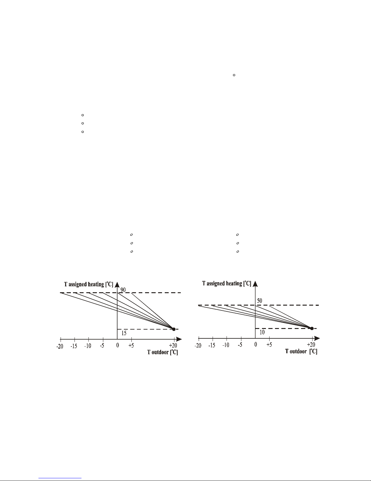
1.5.5.1. Selection of the lower border of the equi-thermal regulation range
The desired temperature range depends of the premises insulation and it is being selected by
submenu „OPTIONS” -> „Equi-thermal reg” (see point 1.4). The first number in the range
shows the minimum outdoor temperature which corresponds to the highest (hottest) heating
one.
There are opportunity for assignation of 6 temperature ranges concerning the outdoor
temperature sensor:
from +5 up to +20 С; from –10 up to +20 С;
from 0 up to +20 С; from –15 up to +20 С;
from –5 up to +20 С; from –20 up to +20 С.
as the heating water assignation is being changed in compliance to figure4.
without room thermostat with room thermostat
The outdoor temperature range (-200C) – (+200C) has to be selected for buildings with small
heat losses where the heating water in the system reaches its maximum value if the outside
temperature is -200C. The ranges of (+50C) – (+200C) and (00C) – (+200C) have to be chosen
for premises with big heat losses like production halls, stores, etc., where the hottest heating
water can be obtained as soon as the outdoor temperature reaches +50C or 00C. Concerning
the factory settings, take into consideration that jumper J2 is placed at position (-100C) –
(+200C).

t:00359 898 606 796 ||| f:00359 596 325 80 ||| info@intiel.com ||| www.intiel.com
9 Peter Beron Str, Pomorie 8000, Bulgaria
- 12 -
Concerning each outside temperature:
- Tout.min. is to be increased in order to increase the heating water temperature;
- Tout.min. is to be decreased in order to decrease the heating water temperature;
1.6 Technical data
1. Power supply: ~230V/50Нz
2. Main board capacity without the servo-actuator: max. 4VA
3. Main board capacity with the servo-actuator: max. 10VA
4. Servo-actuator output: ~230V/50Hz, 5VА
5. Outputs for 1/first/ and 2/second/ stage of the burner:
2 (switching contacts) x 7A/250V/AC
6. Outputs for circulation pumps P1 and P2: phase 5A/250V/AC
7. Output for a circulation pump or a servo-actuator in the domestic hot water circuit:
switching contact 5A/250V/AC
8. Room thermostat input: switching contact
9. Loading of the room thermostat contact: 50mA/12Vss
10. Input for starting the domestic hot water preparation: switching contact
11. Loading of the domestic hot water switching on contact: 50mA/12Vss
12. Protection: IP00
2. Installation of the Controller
2.1 Introduction
The installation of the Controller must be done by a qualified staff. The connection of
the boiler, the mixed valve, servo-actuator and the circulation pump must be in compliance
with the requirements of their producers for a proper installation at central heating systems. It
must be provided enough circulation in the small boiler circuit and in the heating one, in order
to achieve a correct mixture of the water in the heating system. For systems that are equipped
with a circulation pump only in the heating circuit, it must be provided the necessary
gravitation circulation in the boiler circuit either. Therefore, at such systems the mixed valve
must be installed at a height of at least 0.8m above the return boiler water inlet and must be
used pipes and mixed valves with enough vertical section.
2.2 Temperature sensors installation
The Controller is equipped with five temperature sensors, which installation is not
related to an intervention to the existing heating pipe systems. Each sensor is equipped with a
50cm long cable. It can be shortened or connected by a terminal with prolonged two-core
cable with a vertical section for each of them of at least 0.35 mm2.

t:00359 898 606 796 ||| f:00359 596 325 80 ||| info@intiel.com ||| www.intiel.com
9 Peter Beron Str, Pomorie 8000, Bulgaria
- 13 -
At Figure 5 can be seen the schemes of the following systems:
a) System equipped with a four-way valve
b) System equipped with a three-way valve located at position 1 or 2.
The circulation of the water in the small boiler circuit cannot be provided separate
from the heating circuit in systems which are equipped with three-way mixed valve. Thus, if
the mixed valve is closed there is a circulation only in the heating circuit and cannot be
obtained mixture of the outlet boiler water with the returned one. As a result of that the return
boiler water gets cold in short time, that reflects to closing of the mixed valve and going
deeper into that process. In this way the mixed valve will not be opened again. The only
solution about avoiding the low temperature corrosion is to mount the temperature sensor of
the return boiler water “V” together with the sensor of the outlet water temperature “K” and in
the same time setting-up the minimal temperature of the return water at (+650C). In this way
the outlet boiler temperature will vary in the range of (+650C)-(+900C).
The above mentioned installation of the temperature sensors can be used in heating
systems with a gravitation circulation in the small boiler circuit, where incorrect connections
are done by choosing a mixed valve with not enough vertical section or mixed valve with not
enough installation height, or by using pipe system with not enough vertical section.
The temperature sensors must be covered with thermo insulation tape during their
installation on the pipe surface, in order to avoid the ambient temperature influence. The
proper installation gains only the measurement of the water, inside the pipe system.
2.3. Electrical connection of the Controller
The side two covers of the Controller are to be removed in order to provide access to the
terminals. The wiring connection is shown at Figure 6.
K
Boiler
Boiler
K
а) b)
Figure 5
Position .1
Position 2

t:00359 898 606 796 ||| f:00359 596 325 80 ||| info@intiel.com ||| www.intiel.com
9 Peter Beron Str, Pomorie 8000, Bulgaria
- 14 -
2.3.1. Connection of the room thermostat
The Controller can be connected to a different type room thermostat, having
independent switch circuit closer that is switched on, when the real room temperature is lower
than the assigned one. In fact the thermostats equipped with a relay on their outputs (which
are most of the programmable thermostats) and some of the electronics thermostats meet that
requirement. The thermostats having a phase of their output (result of the power supply) have
to be connected by means of a middle relay.
There is a safety voltage of 5 V between the Controller terminals, designed for a room
thermostat connection that allows the thermostat to be connected by a two-core regular cable
2x0.35mm2. The cable is intended to transfer two-digit information and therefore its length
has to be fixed only in relation with its resistance that can reach 100
The room thermostat location is something very important. It is suitable the thermostat
to be placed at the most occupied room in the house that will become a standard for the whole
house (premises) heating. Such areas could be the living-room and the kids’ room in the
family houses. The position of the room thermostat in the kitchen is not correct, because it can
be influenced by the cooking. The location in the corridors is incorrect either, because of its
temperature that differs from the room one. The room thermostat has to be mounted far from
radiators (or other heating elements) and any sun shine influence. It should not be installed on
the outer wall, where the cooling of the masonry will affect to the results of the thermostat
operation. Sometimes the above mentioned unfavorable influences can be used to improve the
thermostat functions, for example when a thermostat with a high hysteresis is getting closer to
the heating elements, providing quicker reaction to the temperature variation; or a thermostat
mounted on the outer wall can provide in time reaction to the variation of the outdoor
temperature.

t:00359 898 606 796 ||| f:00359 596 325 80 ||| info@intiel.com ||| www.intiel.com
9 Peter Beron Str, Pomorie 8000, Bulgaria
- 15 -
2.3.2. Connection of the domestic hot water timer and circulation pump (servo-motor)
For the connection of the domestic hot water thermostat or timer should be followed the same
instructions like for the room thermostat. The switching on contact of the domestic hot water
thermostat is to be connected to terminals X6. In case the domestic hot water preparation is
not provided by the boiler, the terminals have to remain unconnected.
The circulation pump (or the servo-motor) of the domestic hot water is connected by
independent switching contact at terminals X14 (Figure 6). It is protected by fuse F5 (5A). A
terminal X14 provides the neutral and a safety earth. To terminal X13 is to be provided
external phase L1. It can be used the internal phase by means of placing an electrical bridge
between L and L1 from the same terminal.
Some examples of hydraulic and electrical connection schemes for a domestic hot water
circuit are shown at Figure 7:
a) With four-way mixed valve and third circulation pump for domestic hot water circuit
(Figure 7a)
b) With four-way mixed valve and three-way magnet valve in the domestic hot water
circuit (Figure 7b)
a)
b)
Figure 7
Consider the meaning of the above mentioned abbreviations at Figure 7 as follows:
B – boiler
WH – water heater
Switching on the domestic hot water timer, when the water tank temperature is lower
than Tbset will cause the boiler start no matter of the boiler operation mode. It means that it
can be happened even during the summer regime when the mixed valve is closed and the
circulation pump P2 is stopped. The boiler protection against overheating is still active in the
regime of a domestic hot water preparation, as the Controller stops the boiler operation,
without stopping the circulation pump in the domestic hot water circuit, which actually stops
when the water tank temperature reaches 900C. The protection against overcooling of the
return boiler water is active during the domestic hot water preparation, stopping the pump in
the domestic hot water circuit without boiler stopping.
P2
14
13
12
L
N
P1
WH
B
Х2
P3
PE
P2
14
13
12
L
N РЕ
P1 B Х2
WH

t:00359 898 606 796 ||| f:00359 596 325 80 ||| info@intiel.com ||| www.intiel.com
9 Peter Beron Str, Pomorie 8000, Bulgaria
- 16 -
The domestic hot water preparation can be done with a higher priority or with same one
compare to the heating of the premises.
The heating with same priority means if the domestic hot water timer is being
switched on by time, while the heating of the premises is provided (open mixed
valve), then both of them will be provided in the same time. The boiler capacity is
to be shared between the water tank and the premises heating in a dynamic way, as
to the heating is to be sent only that part of the boiler capacity which is not able to
be utilized by the water tank. The gradually heating of the water tank corresponds
to directing grater part of the boiler capacity to the premises. It happens by means
of observing the outlet boiler temperature. In case it drops to 50C bellow the
assignation for the 2nd burner stage of the boiler due to not enough boiler capacity
(switched on 1st and 2nd stage), the four way mixed valve start proceeding closing
steps, thus closing the heating circuit. The consumed capacity is being decreased,
when the valve is being closed and the water tank heated, which referes to
increasing of the outlet boiler temperature. The controller allows mixed valve
opening to the heating circuit when the outlet boiler temperature excceds the
assigned one for the 2nd burner stage, but that happens only in case the room
thermostat or the heating circuit sensor send a command about that.
Heating with a higher priority means that if the domestic hot water timer is being
switched on by time, while the premises heating is being provided (opned mixed
valve), so the Controller will send a signal for a complete mixed valve closing in
order to direct the whole boiler capacity only to the water tank. The boiler capacity
is being decreased as it remains equal to the consumed one from the water tank.
After domestic hot water timer is being switched off or the assigned water tank
temperature is being reached, then the premises heating is to be restored.
The selection of the domestic hot water priority is to be done from submenu
„OPTIONS” -> „Boiler priority” (see point 1.4), where “YES” means high priority and “NO”
– equal priority.
It is possible the domestic hot water preparation to be provided in a combined way,
by means of a boiler and solar panels with a priority of last ones. In this case it is necessary
an additional differential thermostat which is to manage the operation of the solar system
and three way valve. In this case the output relay of the differential thermostat is to be
connected to terminal X6 instead of domestic hot water timer.
2.3.3 Connection the servo-actuator of the mixed valve
The Controller can be connected to a different type of servo-actuator that is in
compliance with mentioned requirements at point 1.6 (Technical data). The manufacture
requirements, concerning the regulation of the Controller output end switches must be
considered during the installation of the servo-actuator. The electrical connection is to be
done at terminals X10. To terminal X10(PE) is to be connected the actuator body, to terminal
X10(N) the common wire of both coils of actuator motor, to terminal X10(-S) the wire whish
is to close the valve, as to terminal X10(+S) the wire which is to open the valve.

t:00359 898 606 796 ||| f:00359 596 325 80 ||| info@intiel.com ||| www.intiel.com
9 Peter Beron Str, Pomorie 8000, Bulgaria
- 17 -
2.3.4 Connection of the boiler
2.3.4.1 Light oil/gas boilers equipped with one or two stage burners.
From menu „OTHER” -> „Kotel Type” is to be selected „gas/liquid fuel” (the option
is default). The burner is to be connected to terminal X17 and X11 (figure 6). By means of
terminal X17(L) a phase is provided to the burner, protected by fuse F3 – 5A. By means of
terminals Х17(N) and Х17(PE) are to be provided respectively a neutral and a protection
earth. Between terminals X11(1S) is placed a switching contact starting 1st burner stage, as
between terminals X11(2S) is placed a switching contact starting the 2nd burner stage.
2.3.4.2 Solid fuel boilers
The electrical managed solid fuel boilers are designed for a connection of a room
thermostat or a timer, as there are terminals for a contact thermostat (placed in the boiler
terminal box), connected in a short circuit by means of an outer electrical bridge. That bridge
is to be removed as the boiler controller is to be connected by means of a cable with the
Controller terminals.
Solid fuel boiler without their own controller
When the boiler is without its own controller, then the boiler operation is managed by
means of fan speed control in relation to the boiler water temperature within the range of 60 85 C.
The control of boiler fan is provided by means of relay switching contact for 1st stage
of the controller, placed on terminals X11(1S). From menu „Kotel Type” is to be selected
„solid fuel 1”.
The boiler operation in this case has the following characteristics. If the boiler
temperature is lower than 60 С the boiler fan operates constantly and it is managed by means
of the room or outdoor thermostat. During smooth increasing of the boiler temperature above
60 С (for example when the valve is too much open) even the room thermostat sends a start
command in the fan operation occurs forced pauses of 15 seconds which are being increased
together with the boiler temperature increasing, as the operation periods are being decreased.
In case the boiler temperature is being increased up to 85 С the pauses are being widen too
much, as the operation periods do not exceed 5 seconds. If the boiler temperature exceeds
85 С, the fan operation is permanently prohibited, despite of the room thermostat could send
a start command. In case the boiler temperature is being increased too fast, the fan operation
can be prohibited constantly after exceeding 60 С. It means the point for constant boiler
stopping depends as well on the speed of boiler temperature increasing as if the speed is faster
the boiler can stop completely within boiler temperature of 60 - 85 С. In this way the
Controller prevents the boiler overheating above the emergency boiler temperature and
emergency opening of the mixed valve, caused by the temperature inertial increasing after the
fan stopping.
Solid fuel boiler with their own controller
If the boiler is equipped with its own operation thermostat, the outlet boiler
temperature is being managed by the boiler thermostat, as the controller only starts or stops
the boiler fan in relation to the commands from the room thermostat, outdoor sensor, return
and outlet boiler temperature, as the last one now fulfils only protection stopping function in
case of boiler overheating above the emergency temperature. The boiler control is provided
by relay switching contact for 1st Controller stage, placed on terminals X11(1S). From menu

t:00359 898 606 796 ||| f:00359 596 325 80 ||| info@intiel.com ||| www.intiel.com
9 Peter Beron Str, Pomorie 8000, Bulgaria
- 18 -
„OTHER” -> „Kotel Type is to be selected „solid fuel 2”. In this case the settings of the
operation thermostats for 1st and 2nd stage does not affect to the fan operation.
2.3.5 Connection of the circulation pump
There is possibility for connection of two circulation pumps P1 and P2
respectively for the small boiler circuit and for the heating one, concerning
heating systems provided with four-way mixed valve. The circulation pump P1
can provide the circulation in the domestic hot water circuit either (see Figure
7b).
single phase circulation pump P1 is to be connected to terminal
X12(PE) – a protection earth, terminal X12(N) – a neutral and terminal
X12(P1) – a phase. The pump protection is provided by fuse F6 (5A).
single phase circulation pump P2 is to be connected to terminal X13(PE) – a
protection earth, terminal X13(N) – a neutral and terminal X13(P2) – a phase. The
pump protection is provided by fuse F4 (5A).
2.3.6 Connection of an emergency (blocking) thermostat.
The emergency (blocking) thermostat is to be connected between terminals X16. This
contact is being opened in case of boiler overheating.
If an emergency thermostat is not provided, so terminals X16 are to be connected in a
short circuit by means of outer electrical bridge.
3. Starting the Controller operation
After the Controller starting must be considered the following check-up:
Control the correctness of the servo-actuator connection.
Regulation of the assigned emergency temperature level of the outlet boiler
water.
Regulation of the assigned temperature level of the working thermostat for
Controller first stage.
Regulation of the assigned temperature level of the working thermostat for the
Controller second stage.
Regulation of the assigned minimal temperature level of the return boiler
water.
Regulation of the assigned minimal temperature level of the heating water.
Specification the boiler starting concerning the domestic hot water preparation.
Specification of the room thermostat control.
3.1 Start-up sequence
3.1.1 First start-up of the Controller
Switch off the burner by removing the cable from X17(L). Then the Controller is to be
switched on.
3.1.2 Control of the correct servo-actuator starting
From menu „OTHER” -> „Test actuator”the actuator can be opened and closed
manually. Press SET button to:
a) The actuator is being opened as light indication 10(>) appears – figure 3a;

t:00359 898 606 796 ||| f:00359 596 325 80 ||| info@intiel.com ||| www.intiel.com
9 Peter Beron Str, Pomorie 8000, Bulgaria
- 19 -
b) The actuator is being closed as light indication 10(<) appears – figure 3a .
The control of the actuator operation is being undertaken by the Controller when the
current menu is being escaped.
In the very beginning the servo-actuator has to be separated of the mixed valve. The
test of the correct direction run of the servo-actuator and the accurate operation of the end
circuit closers have to be done by switching positions “A” and “B”. In case the servo-actuator
moves in the opposite direction than the expected one, the cables of terminals (-S) and (+S)
from X10 are to be replaced.
After fixing the correct run direction of the servo-actuator it is necessary the servoactuator to be waited for to make it complete move until the end position (reaching the end
circuit closer for a “closed”). The regulation element of the mixed valve is to be turned
manually to a closed position, as this is the position for the servo-actuator mounting to the
mixed valve.
3.1.3 Fixing the assigned minimal temperature level of the return boiler water
The minimal temperature level of the boiler return water is to be fixed by submenu
„SETTINGS” -> „Set return Tr” (see point 1.4). The assigned temperature of the return boiler
water can be adjusted within the range of (+45 0C) – (+65 0C). When the real boiler return
water temperature decreases bellow the assigned level, indication 6 appears and the servoactuator starts closing the boiler water flow to the heating circuit.
The recommended levels of the fixed return boiler water temperature are as follows:
Boilers with steel heat-exchangers
from 55 up to 60
Boilers with die-cast heat-exchangers
from 45 up to 55
Solid fuel gasification boilers
from 60 up to 65
3.1.4. Fixing the heating water temperature
The assigned heating water temperature is being kept by the Controller only in winter
mode, but if the room thermostat is switched of for less than 12(24, 36 or 48) hours, or a room
thermostat is not installed. During that time the Controller keeps the heating water
temperature, assigned by transmitter of the outdoor temperature by means of outdoor
temperature sensor. Thus the heating water assignation can be changed in relation to the
outdoor temperature within upper and lower borders, which are to be fixed.
Setting the upper border of the heating water assignation:
It can be done from submenu „SETTINGS” -> „Heat min. Thmах” as it can be fixed within
30 - 85 С.
Setting the lower border of the heating water assignation:
It can be done from submenu „SETTINGS” -> „Heat min. Thmin” as it can be fixed within
15 - 30 С.
The Controller default settings regarding the heating water are as follows, lower border
20 С and upper border 85 С.
Depends on the Controller application there are two ways for keeping the heating water
temperature:
A) With a room thermostat – in case there is no a signal from the room thermostat, the
heating water temperature is being kept by the equithermal regulation, as the upper
border assignation of the heating water is 50 С.;
B) Without a room thermostat – equithermal regulation.

t:00359 898 606 796 ||| f:00359 596 325 80 ||| info@intiel.com ||| www.intiel.com
9 Peter Beron Str, Pomorie 8000, Bulgaria
- 20 -
3.1.5 Fixing the boundary temperature level of the outlet boiler water
The emergency opening of the servo-valve during exceeding of the boundary
temperature level of the boiler can be easily checked during boiler start-up. It can be carried
out when the mixed valve is not open yet, the working thermostat at a first burner stage is
fixed at its maximum level and the settled boundary level of the outlet boiler water is at its
minimal level. Mostly the boiler behavior is that if the working thermostat is switched off the
boiler temperature keeps increasing in case the heating water would not be leaded (for
example that could be happen at a closed mixed valve). When the boundary temperature level
of the heating water is reached the light indication 7 appears (see Figure 3a), the boiler must
be stopped, the mixed valve must be opened and the circulation pumps P1 and P2 must
operate, it is possible to start operation of the circulation pump in the domestic hot water
circuit in case the water tank temperature is less than 900C. The boundary emergency boiler
water temperature can be adjusted from menu „SETTINGS” -> „Set limit Tk” in the range of
(+90 0C) – (+105 0C). The setting is to be done in a way that after activating the first
stage, the boiler would not be stopped by the working thermostat, neither to be able to
reach the assigned boundary level of the outlet boiler temperature. That means the
lowest possible temperature setting is of the 1st stage of the working thermostat (for
example +800C), the fixed emergency boiler temperature is higher (for example +950C)
and the emergency thermostat has the most possible settings (for instance +1050C). The
boiler emergency thermostat is an automatic discharger of hot water during overheating
of the boiler and operates together with an automatic filling valve with a cold water of
the water-conduit.
If the boiler temperature of the outlet boiler water drops bellow the fixed boundary
temperature level, the indication 7 stops and the Controller goes independently into the settled
operation mode with a control of the servo-valve.
Figure 8 shows the adjusting of the outlet emergency water temperature of the boiler
at:
a) High temperature level Tp;
b) Correct temperature level Tp,
where:
Tn is a temperature of the emergency boiler thermostat
Tb is a boiler temperature (in our case an emergency one)
Tp is a temperature of 1st stage of the working thermostat
3.1.6 Adjusting the assignation of the working thermostats for 1st and 2nd burner stage
About 1st stage – from menu „SETTINGS” -> „Thermostat st1” is to be fixed an operation
temperature of 1st stage within 75 - 90 С;
Emergency boiler stopping
CONTROLLER safety
function
Without installed
controller
Тn
Тb
Тр
Тn
Тb
Тр
Т
t[min]
Т
t[min]
a)
b)
Figure 8

t:00359 898 606 796 ||| f:00359 596 325 80 ||| info@intiel.com ||| www.intiel.com
9 Peter Beron Str, Pomorie 8000, Bulgaria
- 21 -
About 2nd stage – from menu „SETTINGS” -> „Thermostat st2” is to be fixed an
operation temperature of 2nd stage within 60 - 75 С;
Regarding solid fuel boiler, managed by the switching contact of 1st stage (see point
2.3.4.2) thermostats about 1st and 2nd stages does not affect to the boiler operation.
3.1.7 Fixing the operation and stop time of the motor actuator
The actuator operation and stop time is to be fixed from submenu OPTIONS”->
„Actuator speed” within 1-100%, as 1% corresponds to 1 second. For example, is the setting
of “Actuator speed” is 10%, it means 10seconds operation and 90 seconds a pause. Regarding
faster actuators it is to be fixed less operation time and vice versa. The default setting is 20%.
3.1.8 Control of the domestic hot water thermostat operation
If no one of the indications 6, 7 appear (figure 3a) or Th is not bellow the assigned
value, then short circuit between terminals X4(TB), as well between terminals X6 (BGW) is
to start the boiler operation, as well the relay managed circulation pump P3.
3.1.9 Control of the room thermostat regulation
If no one of the indications 6, 7 (figure 3a) or Th is not bellow the assigned value, then
after a room thermostat switching on, the mixed valve is to start opening and the boiler is to
be started. After room thermostat switching off – the valve is to start closing as the boiler is to
be stopped. In case of constant switching of the room thermostat the controller move the
motor actuator in a step movement to positions “open” and “close”

t:00359 898 606 796 ||| f:00359 596 325 80 ||| info@intiel.com ||| www.intiel.com
9 Peter Beron Str, Pomorie 8000, Bulgaria
- 22 -
3.2 Detection of possible installation failures
Before looking for some occurred failures, it must be checked up the state of the
control indications 6 and 7, which lighting signalize, the Controller fulfils its priority
functions and its operation is in compliance with above mentioned.
Failure Indication
Possible Cause
Trouble-shooting
There is no activated light
indication on the front panel
A burned fuse F1 –
0.125A
Replace the fuse F1 with new
one after switching off the
power supply.
A circulation pump does not
operate.
A burned fuse F4 – 5A,
F5 – 5A, F6 – 5A
Replace the fuses F4, F5 or
F6 with new one after
switching off the power
supply.
The servo-actuator does not
operate
A burned fuse F2 – 0.5A
Replace the fuse F2 with new
one after switching off the
power supply.
The servo-actuator is turning in
a wrong direction.
Not correct connected
servo-actuator
Replace the positions of
cables at terminals X10(S+)
and (S-)
Any of the observed
temperatures is indicated with
“too high”
Not connected or
damaged sensor or
interrupted cable
The connection is to be
checked up or the sensor
replaced
Any of the observed
temperatures is indicated with
“too low”
Short circuit in the sensor
or temperature bellow
300C
The sensor is to be replaced
The premises cannot be heated
to the desired temperature
Low temperature of the
boiler water
Increase the assignation of
the working thermostat for
first burner stage.
Low heating water
temperature
Increase Tout.min.
Check up the heating system
settings from point 3.1.4.
4. The Controller maintenance
The system starts its operation by switching on the power supply button. The further
maintenance of the Controller can be done by the room thermostat and that provides only a
regulation of the desired room temperature level. The Controller keeps such a temperature of
the heating water that is able to provide reaching the assigned temperature level by the room
thermostat.
In case there is overheating in the rest of the rooms it is necessary to close the
regulation valves of their heating elements (radiators, bath radiators, etc.) Other decision that
can provide a proper regulation of the temperature in those rooms is the installation of
thermostatic valves. But in this way, the time programming of their temperature changes
cannot be used.
The Controller transition to a summer mode is being assigned by the room thermostat.
As it was mentioned the Controller periodically tests the circulation pumps and the mixed
valve and therefore it is not recommended it is to be switched off during the summer. An
undesired boiler switching during the summer can be avoided by switching off the room

t:00359 898 606 796 ||| f:00359 596 325 80 ||| info@intiel.com ||| www.intiel.com
9 Peter Beron Str, Pomorie 8000, Bulgaria
- 23 -
thermostat (in case it is equipped with such a switch) or by fixing a lowest possible room
temperature (for example anti-freezing temperature, which is preliminary adjusted with most
of the room thermostats). For example it can be a not-freezing temperature that is adjusted to
most of the room thermostats. Then to go back to winter mode is enough to get back to the
preliminary program settings.
The complete stopping of the heating system can be provided by switching off the Controller
and boiler power supply.
5. Opening of the Controller cover
5.1. Remove protective caps „ 1 ”
5.2. Press pin „2” as at the same time pick up cover „ 3 ”

t:00359 898 606 796 ||| f:00359 596 325 80 ||| info@intiel.com ||| www.intiel.com
9 Peter Beron Str, Pomorie 8000, Bulgaria
- 24 -
6. Storage
The Controller has to be kept in the provided by the manufacturer packages, at an
ambient temperature of (+5 0C) up to (+35 0C) and a maximal relative humidity of 65%.
SETTINGS and PARAMETERS
Symbols
Description
Range
Default setting
Customer’s settings
Set limit Tk
Assigned emergency boiler
temperature of the outlet water
85 ÷ 105° С
95° С
Set return Tr
Assigned minimum temperature
of the return boiler water
25 ÷ 65° С
45° С
Th min
Lower border of heating water
assignation
15 ÷ 30° С
20° С
Th max
Upper border of heating water
assignation
30 ÷ 85° С
85° С
Set boiler Tb
Assigned water tank
temperature
30 ÷ 80° С
60° С
Thermost-at
st1
Operation thermostat
assignation of 1st burner stage
75 ÷ 90° С
85° С
Thermost-at
st2
Operation thermostat
assignation of 2nd burner stage
60 ÷ 75° С
65° С
Твънш. мин
Outdoor temperature
corresponding to the hottest
heating water temperature
during equi-thermal regulation
5 ÷ -20° С
-10° С
Night
drop set
Temperature assignation
regarding the night drops
5÷ 15° С
5° С
Actuator speed
Servo actuator speed
1 ÷ 100%
20%
Room
thermostat
Presence of room thermostat
YES/NO
NO
Boiler priority
Heating the water tank with
equal or higher priority
YES/NO
NO
Summer
regime
Time after which the Controller
goes to a summer mode, in case
of no signal from a room
thermostat or sensor “O”
12 hours
24 hours
36 hours
48 hours
12 hours
Kotel Type
Defines the boiler type in
relation to the fuel and own
thermostat availability
gas/liquid fuel
solid fuel 1
solid fuel 2
gas/liquid
fuel

t:00359 898 606 796 ||| f:00359 596 325 80 ||| info@intiel.com ||| www.intiel.com
9 Peter Beron Str, Pomorie 8000, Bulgaria
- 25 -
7. Warranty
The warranty period is 24 months following the purchase date of the unit or its
installation by a qualified staff, but not exceeding 28 months after the production date. The
warranty is extended to the malfunctions that occur during the warranty period and are result
of the production reasons or defective used parts.
The warranty does not relate to malfunctions corresponding to not-qualified
installation, activities directed to the product body interference, not regular storage or
transport.
The repairs during the warranty period can be done after correct filling of the
manufacturer warranty card
 Loading...