

In the Swim Automatic Solar Blanket Reel, S5430 System Installation And Operation Manual
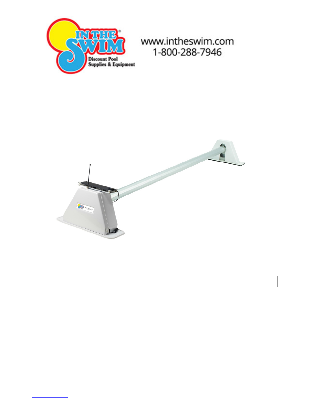
In the Swim® Solar/Battery Powered Solar Blanket Reel
Installation / Operation Guide
Please Read, Follow, and
Save this Instruction Manual.
In the Swim® Solar/Battery Powered Solar Blanket Reel is recommended for use on rectangular
shaped pools with or without diving boards.
The In the Swim® Solar/Battery Powered Solar Blanket Reel system should only be used for the
intended application.
PBITS001
INTRODUCTION

IMPORTANT SAFETY PRECAUTIONS
READ AND FOLLOW ENTIRE INSTRUCTION MANUAL
AND ALL PRECAUTIONS, PRIOR TO INSTALLING,
USING, OR TROUBLESHOOTING THIS EQUIPMENT.
• Read, follow, and save the entire instruction manual
• Use the system only in the intended manner.
• Remember, solar blankets are not safety covers.
• Remove the solar blanket completely from the pool before using the pool.
• The system is intended to be stationary. It is not designed to be mounted on a caster-
equipped stand.
• Visually inspect the pool prior to retracting or extending the solar blanket. The pool should be
clear of occupants and other items that might conflict with the solar blanket.
• Store the remote control and in a secure location in order to prevent unauthorized operation.
• Do not attempt any technical repairs without proper training or first calling
Technical Support at 1-866-778-POOL(7665). Failure to do so may result in denial of
warranty claims.
.
GETTING STARTED
Required Tools:
• 5/16 & 7/16 wrenches or sockets
• #2 Phillips screwdriver
• Drill
• 1/4” and 5/32” drill bits
• Flat blade screwdriver
Select the Location
Select a location at one of the narrow ends of the pool. The location must be away from the ladder.
Typical Layout

Drive
Stand
Pool Deck
Level
Installation
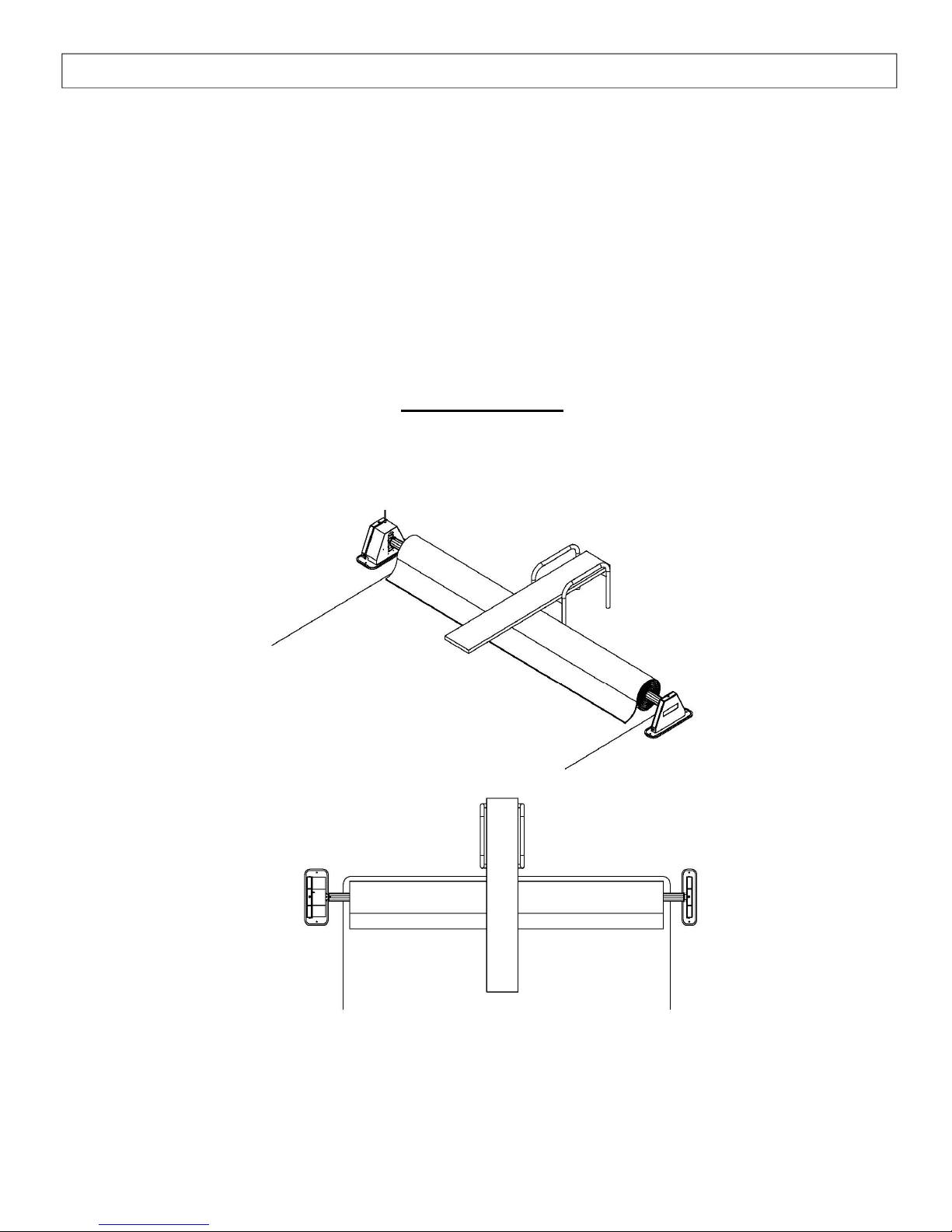
1) Position the Stands
Position the stands in the selected location at one of the narrow ends of the pool. The stands come
assembled in the middle of the height adjustment range.
Height adjustment
The height of the reel system is adjustable through a wide range. The height of the cross tube can be
changed by moving the hub assemblies to different height settings.
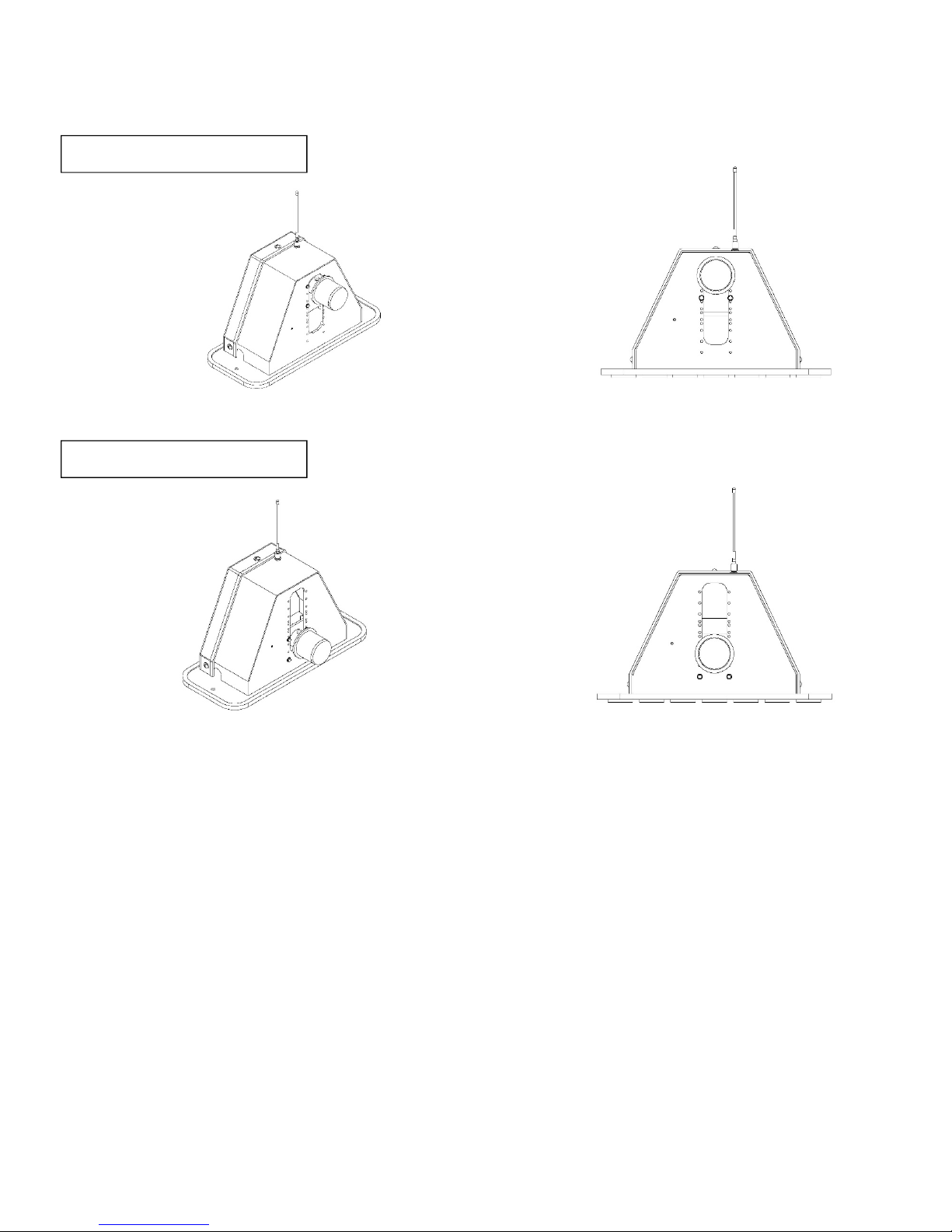
Example- Highest Setting
Example- Lowest Setting
Adjusting Stand Height
1. Remove the drive and idler stand covers. The covers are each held in place by three screws.
2. Remove bolts that attach motor case to stand. Position motor / gearbox assembly at the desired
height. Insert and tighten bolts.
3. Remove bolts and nuts that attach the idler hub and position hub to match the drive stand hub
location.
4. Reinstall bolts, washers and nuts and tighten.
5. Leave the drive stand cover off. Install the idler stand cover, if desired.
 Loading...