

Page 1

(91PO) 36", 42" & 48" 2-SECTIONS POOL LADDER ENGLISH 7.5” X 10.3” PANTONE 295U 10/13/2011
nglish
E
IMPORTANT
SAFETY RULES
Read, understand, and follow all
instructions carefully before installing
and using this product.
Pool Ladder
Owner’s Manual For:
36in (91 cm), 42in (107 cm) & 48in (122 cm)
models
91PO
OOWWNNEERR’’SS MMAANNUUAALL
For illustrative purposes only. Pool is not provided.
Don’t forget to try these other fine Intex products: Pools, Pool Accessories,
Inflatable Pools and In-Home Toys, Airbeds and Boats available at fine
retailers or visit our website.
IIMMPPOORRTTAANNTT!!
DO NOT RETURN PRODUCT TO STORE
To purchase parts and accessories or to obtain non-technical assistance,
Visit www.intexcorp.com
For technical assistance and missing parts call us toll-free (for U.S. and Canadian Residents):
1-800-234-6839
Monday through Friday, 8:30am to 5:00pm Pacific Time
091-*PO-R2-1210
Page 2

(91PO) 36", 42" & 48" 2-SECTIONS POOL LADDER ENGLISH 7.5” X 10.3” PANTONE 295U 10/13/2011
E
Warnings............................................................................. 3
Parts List & References...................................................... 4-6
Setup Instructions.............................................................. 7-9
General Aquatic Safety...................................................... 10
Pool Safety Sign................................................................. 11
nglish
91PO
SAVE THESE INSTRUCTIONS
TTAABBLLEE OOFF CCOONNTTEENNTTSS
Page 2
Page 3

(91PO) 36", 42" & 48" 2-SECTIONS POOL LADDER ENGLISH 7.5” X 10.3” PANTONE 295U 10/13/2011
nglish
E
IMPORTANT SAFETY RULES
Read, Understand and Follow All Instructions Carefully Before Installing and Using this Product.
WARNING
• Supervise children and those with disabilities at all times.
• Always assist children when they use the ladder to avoid falls and/or
serious injury.
• Never dive or jump from this ladder.
• Locate the ladder on a level, solid base.
• One person on this ladder at a time.
• Maximum load: 300 lbs (136 kg). Complies with NF P90-317
strength requirements.
• Face the ladder at all times for entry/exit of pool.
• Remove and secure ladder when pool is not occupied.
• Do not swim under, through or behind ladder.
• Check all nuts and bolts regularly to ensure ladder stays sturdy.
• If swimming at night use artificial lighting to illuminate all safety
signs, ladders, pool floor and walkways.
• Assembly and disassembly by adults only.
• This ladder is designed and manufactured for a specific pool wall
height and/or deck of the pool.
• The non-respect of the maintenance instruction may result in huge
risk for health, particularly for children.
• Only use this ladder for the purposes described in this manual.
91PO
SSAAFFEETTYY RRUULLEESS
FAILURE TO FOLLOW THESE WARNINGS MAY RESULT IN
BROKEN BONES, ENTRAPMENT, PARALYSIS, DROWNING OR
OTHER SERIOUS INJURY.
These product warnings, instructions and safety rules provided with the
product represent some common risks of water recreation devices and
do not cover all instances of risk and danger. Please use common
sense and good judgment when enjoying any water activity.
SAVE THESE INSTRUCTIONS
Page 3
Page 4
(91PO) 36", 42" & 48" 2-SECTIONS POOL LADDER ENGLISH 7.5” X 10.3” PANTONE 295U 10/13/2011
W
A
R
N
I
N
G
:
A
B
A
B
B
A
B
A
B
B
1
4 5
7
PARTS LIST
2
8
nglish
E
91PO
3
6
A
B
PPAARRTTSS LLIISSTT
9
10
NOTE: Drawings for illustration purpose only. Actual product may vary. Not to
scale.
This ladder is designed and manufactured for Intex pool wall height:
Item # Pool Wall Height
58972 36in (91 cm)
11462 (silver & white) 36in (91 cm)
58973 42in (107 cm)
11395 (silver & white) 42in (107 cm)
58974 (white & blue) 48in (122 cm)
10903 (silver & white) 48in (122 cm)
SAVE THESE INSTRUCTIONS
Page 4
Page 5

(91PO) 36", 42" & 48" 2-SECTIONS POOL LADDER ENGLISH 7.5” X 10.3” PANTONE 295U 10/13/2011
E
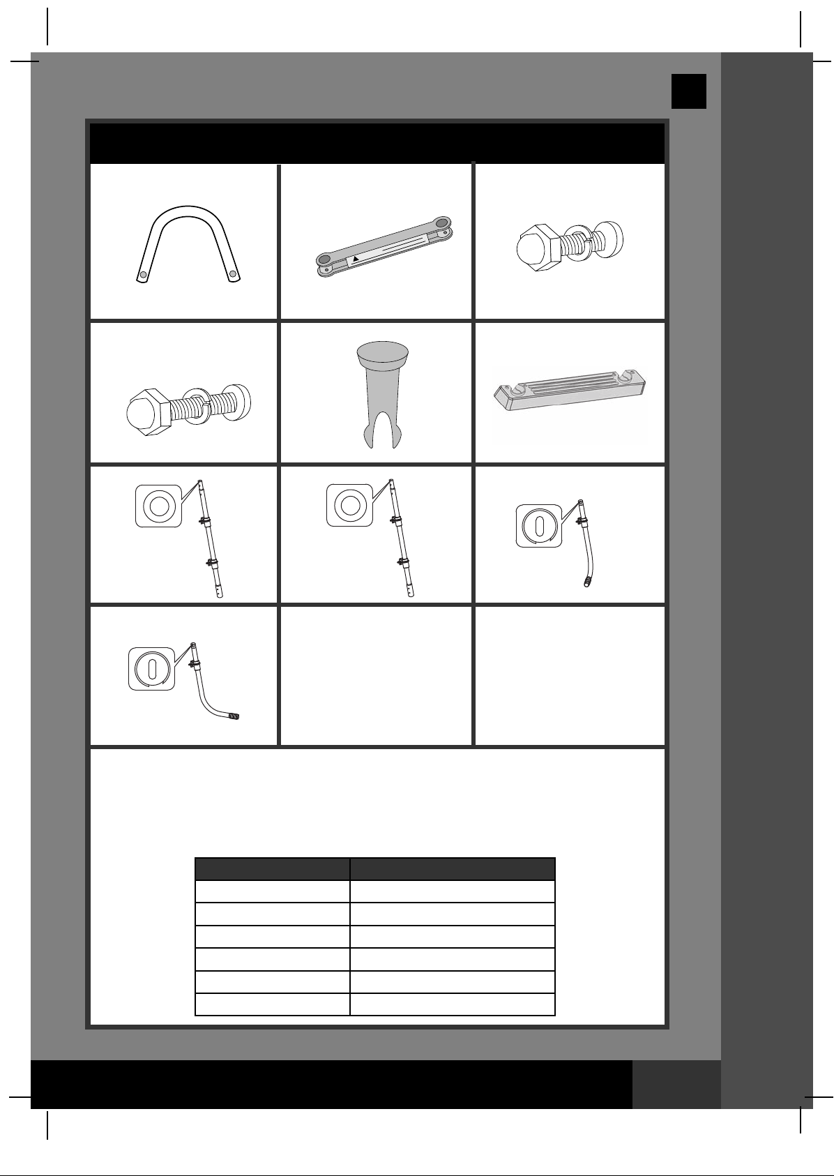
PARTS REFERENCE
efore assembling your product, please take a few minutes to check the contents
B
and become familiar with all the parts.
2
1
7
3
4
5
6
8
10
nglish
91PO
9
36in (91 cm) & 42in (107 cm) models
NOTE: Drawings for illustration purpose only. Actual product may vary. Not
to scale.
REF. NO. DESCRIPTION
1 U-SHAPED TOP RAIL 2 2
2 TOP BRACE 2 2
3
SHORT FASTENER FOR U-SHAPED TOP RAIL (WITH 1 EXTRA)
4 LONG FASTENER FOR TOP BRACE (WITH 1 EXTRA) 5 5
STEP MOUNTING PIN (WITH 2 EXTRA)
5
6 STEP 6 6
7 UPPER SIDE LEG (“A” ENGRAVED ON TOP CAP) 2 2
8 UPPER SIDE LEG (“B” ENGRAVED ON TOP CAP) 2 2
9
LOWER J-SHAPED SIDE LEG (“A” ENGRAVED ON TOP CAP)
10
LOWER J-SHAPED SIDE LEG (“B” ENGRAVED ON TOP CAP)
REF.
NO.
1
U-SHAPED TOP RAIL
2
TOP BRACE
3
SHORT FASTENER FOR U-SHAPED TOP RAIL (WITH 1 EXTRA)
4
LONG FASTENER FOR TOP BRACE (WITH 1 EXTRA)
STEP MOUNTING PIN (WITH 2 EXTRA)
5
6
STEP
7
UPPER SIDE LEG (“A” ENGRAVED ON TOP CAP)
8
UPPER SIDE LEG (“B” ENGRAVED ON TOP CAP)
9
LOWER J-SHAPED SIDE LEG (“A” ENGRAVED ON TOP CAP)
10
LOWER J-SHAPED SIDE LEG (“B” ENGRAVED ON TOP CAP)
DESCRIPTION
#58972 #11462 #58973 #11395
11128 11530 11164
11094 11397 11094
10228 10228 10228
10227 10227 10227
10349 10913 10349
10348 10914 10348
11091A 11531A 11162A
11091B 11531B 11162B
10895A 11532A 11163A
10895B 11532B 11163B
SPARE PART NO.
LADDER SIZE
& QUANTITIES
36” 42”
5 5
26 26
2 2
2 2
11396
11397
10228
10227
10913
10914
11398A
11398B
11399A
11399B
PPAARRTTSS RREEFFEERREENNCCEE
SAVE THESE INSTRUCTIONS
Page 5
Page 6

(91PO) 36", 42" & 48" 2-SECTIONS POOL LADDER ENGLISH 7.5” X 10.3” PANTONE 295U 10/13/2011
E
PARTS REFERENCE (continued)
efore assembling your product, please take a few minutes to check the contents
B
and become familiar with all the parts.
1
2
7
3
4
5
6
8
10
nglish
91PO
9
48in (122 cm) model
NOTE: Drawings for illustration purpose only. Actual product may vary. Not
to scale.
REF. NO. DESCRIPTION QUANTITY
1 U-SHAPED TOP RAIL 2
2 TOP BRACE 2
3
4 LONG FASTENER FOR TOP BRACE (WITH 1 EXTRA) 5
5
6 STEP 8
7 UPPER SIDE LEG (“A” ENGRAVED ON TOP CAP) 2
8 UPPER SIDE LEG (“B” ENGRAVED ON TOP CAP) 2
9
10
REF. NO. DESCRIPTION
1 U-SHAPED TOP RAIL
2 TOP BRACE
3
4 LONG FASTENER FOR TOP BRACE (WITH 1 EXTRA)
5
6 STEP
7 UPPER SIDE LEG (“A” ENGRAVED ON TOP CAP)
8 UPPER SIDE LEG (“B” ENGRAVED ON TOP CAP)
9
10
SHORT FASTENER FOR U-SHAPED TOP RAIL (WITH 1 EXTRA)
STEP MOUNTING PIN (WITH 2 EXTRA)
LOWER J-SHAPED SIDE LEG (“A” ENGRAVED ON TOP CAP)
LOWER J-SHAPED SIDE LEG (“B” ENGRAVED ON TOP CAP)
SPARE PART NO.
SHORT FASTENER FOR U-SHAPED TOP RAIL (WITH 1 EXTRA) 10810 10810
STEP MOUNTING PIN (WITH 2 EXTRA)
LOWER J-SHAPED SIDE LEG (“A” ENGRAVED ON TOP CAP)
LOWER J-SHAPED SIDE LEG (“B” ENGRAVED ON TOP CAP)
5
34
2
2
#58974 #10903
11167 11171
11168 11172
10227 10227
10349 10913
10348 10914
11165A 11169A
11165B 11169B
11166A 11170A
11166B 11170B
PPAARRTTSS RREEFFEERREENNCCEE
SAVE THESE INSTRUCTIONS
Page 6
Page 7

(91PO) 36", 42" & 48" 2-SECTIONS POOL LADDER ENGLISH 7.5” X 10.3” PANTONE 295U 10/13/2011
B
A
B
A
B
nglish
E
LADDER SETUP
These assembly instructions are the same for the 3-step and 4-step
ladders. The assembly drawings show the 3-step ladder.
TOOLS REQUIRED: One (1) Phillips screwdriver
One (1) pair of pliers or a small adjustable wrench
IMPORTANT: Do not fully tighten fasterners until last assembly operation.
WARNING
ASSEMBLE THE LEGS BEFORE INSTALLING THE LADDER STEPS.
FAILURE TO ASSEMBLE THE LEGS BEFORE INSTALLING THE
STEPS MAY ALLOW THE LEGS TO SEPARATE FROM THE LADDER
DURING USE, POSSIBLY RESULTING IN SERIOUS INJURY OR DEATH.
1. IDENTIFY PARTS: It is very important to lay out the parts correctly and
identify which parts connect together before starting the assembly.
Although some parts look alike, they are not always interchangeable.
Refer to the parts list.
91PO
WARNING
INCORRECTLY CONNECTED PARTS MAY RESULT IN AN UNSTABLE
LADDER OR LADDER FAILURE WHICH CAN CAUSE FALLING AND
PERSONAL INJURY OR DEATH.
2. LEG ASSEMBLY (refer to figure 1):
There are two straight upper leg
parts (7) marked “A” and two
J-shaped lower leg parts (9) also
marked “A”.
There are also two straight upper leg
parts (8) marked “B” and two lower
J-shaped leg parts (10) marked “B”.
The markings are located on the top
plastic caps at the end of each leg
part. Connect the “A” upper leg parts
with “A” lower leg parts as follows:
• Align the groove on the lower leg
part with the notch on the upper
leg part - see figure 1.
• Insert the lower leg part into the
upper leg part and then turn it
clockwise to lock it in place.
• Verify that the plastic step
mounting fixtures are aligned and facing the same
way on upper and lower leg part. Also lift the upper leg part and verify
that the lower leg part is properly inserted/locked and doesn’t fall out.
Repeat these steps to connect the “B” upper leg parts with “B” lower leg
parts accordingly. NOTE: DO NOT MIX “A” PARTS WITH “B” PARTS!
You now have two complete “A” legs and two complete “B” legs.
A
A
B
B
1
SSEETTUUPP IINNSSTTRRUUCCTTIIOONNSS
SAVE THESE INSTRUCTIONS
Page 7
Page 8

(91PO) 36", 42" & 48" 2-SECTIONS POOL LADDER ENGLISH 7.5” X 10.3” PANTONE 295U 10/13/2011
A
B
A
A
A
LADDER SETUP (continued)
3. STEP INSTALLATION (refer to
figures 2.1 through 2.3):
Take one complete “A” leg and one
complete “B” leg. The steps (6) attach
to the mounting fixtures on each leg.
Note the markings “A” and “B” next to
each attachment slot on each step.
“A” side of the step attaches to “A” leg
and “B” side of the step attaches to
“B” leg - see figure 2.1.
Slide the step over the mounting
fixture on the leg and push it all the
way until it is completely flush with
the mounting fixture.
Any protrusion of the mounting
fixture beyond the step indicates
the step is upside-down or
otherwise wrongly positioned.
After ensuring the step is placed
correctly, push the mounting pins (5)
into the holes on the step, securing
the step to the mounting fixture
– see figure 2.2 (four pins for each
step).
Repeat the process with the
remaining steps and with the
remaining pair of legs.
When finished, you will have two
complete sides of the ladder. Each
side should resemble figure 2.3.
nglish
E
.1
2
B
A
2.2
A
2.3
B
91PO
4. TOP BRACE INSTALLATION – ONE
SIDE AT A TIME (refer to figure 3):
Identify hole “A” and hole “B” on the
top braces (2), marked accordingly at
each end. Slide the top braces over
the legs, making sure hole “A” of
one brace slides over leg “A” and
hole “B” of the other brace over
leg “B”. The small holes on the side of
braces should align with the lower
holes on the legs.
Fasten each brace to the legs using
the longer fasteners/screws (4).
Do not yet attach the other side of the
ladder to the top braces – this
assembly step will follow later.
SAVE THESE INSTRUCTIONS
3
SSEETTUUPP IINNSSTTRRUUCCTTIIOONNSS
A
B
Page 8
Page 9

(91PO) 36", 42" & 48" 2-SECTIONS POOL LADDER ENGLISH 7.5” X 10.3” PANTONE 295U 10/13/2011
A
LADDER SETUP (continued)
5. U-SHAPED TOP RAIL
INSTALLATION (refer to figure 4):
Install the U-shaped top rails (1)
onto the legs above the top brace
(2) and fasten them with the
shorter fasteners/screws (3)
– see figure 4.
6. INSTALLATON OF THE
REMAINING LADDER SIDE
(refer to figure 5):
With all the top rail and top brace
holes in alignment, slide the
remaining ladder side from the
underside into its proper position.
Make sure the “A” leg slides into
hole “A” of the top brace and the
“B” leg slides into hole “B” of the
corresponding top brace.
Fasten all parts using the
appropriate fasteners/screws (4)
and (3), as described earlier.
nglish
E
4
5
91PO
7. BEFORE USE OF LADDER:
With all parts now in place, verify
that all fasteners/screws are fully
tightened and apply downward
pressure to each step to be sure
they are fully anchored in place. If
your ladder came with a ladder
barrier, proceed to instructions for
ladder barrier installation,
otherwise proceed to placing
the ladder over the side wall of
your pool, with one side of the
ladder located inside the pool and
the other side outside of the
pool - see figure 6.
Estimated assembly time 20~45
minutes. (Note the assembly time
is only approximate and individual
assembly experience may vary.)
WARNING
• Locate ladder on a level, solid base and make sure the ladder is
stable and safe to climb.
• Remove and secure ladder away from the pool when the pool is
not in use to prevent unauthorized, unintentional or unsupervised
pool entry.
• Check all nuts and bolts regularly and before each use to ensure
the ladder is sturdy. See maintenance instructions.
8. MAINTENANCE:
Regularly check all nuts, bolts, step mounting fixtures and step mounting
pins to ensure all parts are secured properly and the ladder is sturdy.
Bring the ladder indoors and store in a safe and dry area, preferably
between 32 degrees Fahrenheit (0 degrees Celsius) and 104 degrees
Fahrenheit (40 degrees Celsius).
6
SSEETTUUPP IINNSSTTRRUUCCTTIIOONNSS
SAVE THESE INSTRUCTIONS
Page 9
Page 10

(91PO) 36", 42" & 48" 2-SECTIONS POOL LADDER ENGLISH 7.5” X 10.3” PANTONE 295U 10/13/2011
nglish
E
GENERAL AQUATIC SAFETY
Water recreation is both fun and therapeutic. However, it involves
inherent risks of injury and death. To reduce your risk of injury, read and
follow all product, package and package insert warnings and instructions.
Remember, however, that product warnings, instructions and safety
guidelines cover some common risks of water recreation, but do not cover all
risks and dangers.
For additional safeguards, also familiarize yourself with the following general
guidelines as well as guidelines provided by nationally
recognized Safety Organizations:
• Demand constant supervision. A competent adult should be appointed as a
“lifeguard” or water watcher, especially when children are in and around the pool.
• Learn to swim.
• Take the time to learn CPR and first aid.
• Instruct anyone who is supervising pool users about potential pool
hazards and about the use of protective devices such as locked doors, barriers,
etc.
• Instruct all pool users, including children what to do in case of an emergency.
• Always use common sense and good judgement when enjoying any water
activity.
• Supervise, supervise, supervise.
91PO
For additional information on safety, please visit
• The Association of Pool and Spa Professionals: The Sensible Way to
Enjoy Your Aboveground/Onground Swimming Pool www.nspi.org
• American Academy of Pediatrics: Pool Safety for Children
www.aap.org
• Red Cross www.redcross.org
• Safe Kids www.safekids.org
• Home Safety Council: Safety Guide www.homesafetycouncil.org
• Toy Industry Association: Toy Safety www.toy-tia.org
SAFETY IN YOUR POOL
Safe swimming depends on constant attention to the rules. The "NO DIVING"
sign within this manual can be posted near your pool to help keep everyone
alert to the danger. You may also wish to copy and laminate the sign for
protection from the elements.
SAVE THE CARTON FOR STORAGE AND THE INSTRUCTIONS
FOR RE-ASSEMBLY
SSAAFFEETTYY GGUUIIDDEELLIINNEESS
SAVE THESE INSTRUCTIONS
Page 10
Page 11

(91PO) 36", 42" & 48" 2-SECTIONS POOL LADDER ENGLISH 7.5” X 10.3” PANTONE 295U 10/13/2011
POST THIS WARNING NEAR YOUR POOL
nglish
E
91PO
WARNING
!
NO DIVING OR JUMPING
SHALLOW WATER
DIVING MAY RESULT IN PERMANENT INJURY OR DEATH
• No glass in pool area.
• Be Safe. Swim with a friend.
• Don’t swim when using alcohol or drugs.
• Children must be accompanied by an adult.
• Be familiar with the pool before swimming.
• No running, jumping, or horseplay in or around pool.
TO AVOID SERIOUS INJURY ALL POOL USERS MUST KNOW AND FOLLOW THESE SAFETY RULES.
SAVE THESE INSTRUCTIONS
Page 11
Page 12

®
(91PO) 36", 42" & 48" 2-SECTIONS POOL LADDER ENGLISH 7.5” X 10.3” PANTONE 295U 10/13/2011
nglish
E
For Residents of the U.S. & Canada:
INTEX RECREATION CORP.
Attn: Consumer Service
1665 Hughes Way
Long Beach, CA 90801
Phone: 1-800-234-6839
Fax: (310) 549-2900
Consumer Service Hours:
8:30 am to 5:00 pm Pacific time
Monday thru Friday only
Website: www.intexcorp.com
For Residents outside of the U.S. and Canada:
Please refer to the Service Center Locations
©2011 Intex Marketing Ltd. - Intex Development Co. Ltd. Intex Trading Ltd. - Intex Recreation Corp.
All rights reserved/Tous droits réservés/Todos los
derechos reservados/Alle Rechte vorbehalten.
Printed in China/Imprimé en Chine/Impreso en
China/Gedruckt in China.
®™ Trademarks used in s ome countries of the world under
license from/®™ Marques utilisées dans certains pays sous
licence de/Marcas registradas utilizadas en algunos países
del mundo bajo licencia de/Warenzeichen verwendet in
einigen Ländern der Welt in Lizenz von/Intex Marketing Ltd.
to/à/a/an Intex Trading Ltd., Intex Development Co. Ltd.,
G.P.O Box 28829, Hong Kong & Intex Recreation Corp.,
P.O. Box 1440, Long Beach, CA 90801 • Distributed in the
European Union by/Distribué dans l’Union Européenne
par/Distribuido en la unión Europea por/Vertrieb in der
Europäischen Union durch/Intex Trading B.V., P.O. Box nr.
1075 – 4700 BB Roosendaal – The Netherlands
I N T E X
 Loading...