

Page 1
(162) MODEL SF15220 SAND FILTER PUMP ENGLISH 7.5” X 10.3” PANTONE 295U 09/28/2010
IMPORTANT
SAFETY RULES
Read, understand, and follow all
instructions carefully before
installing and using this product.
TM
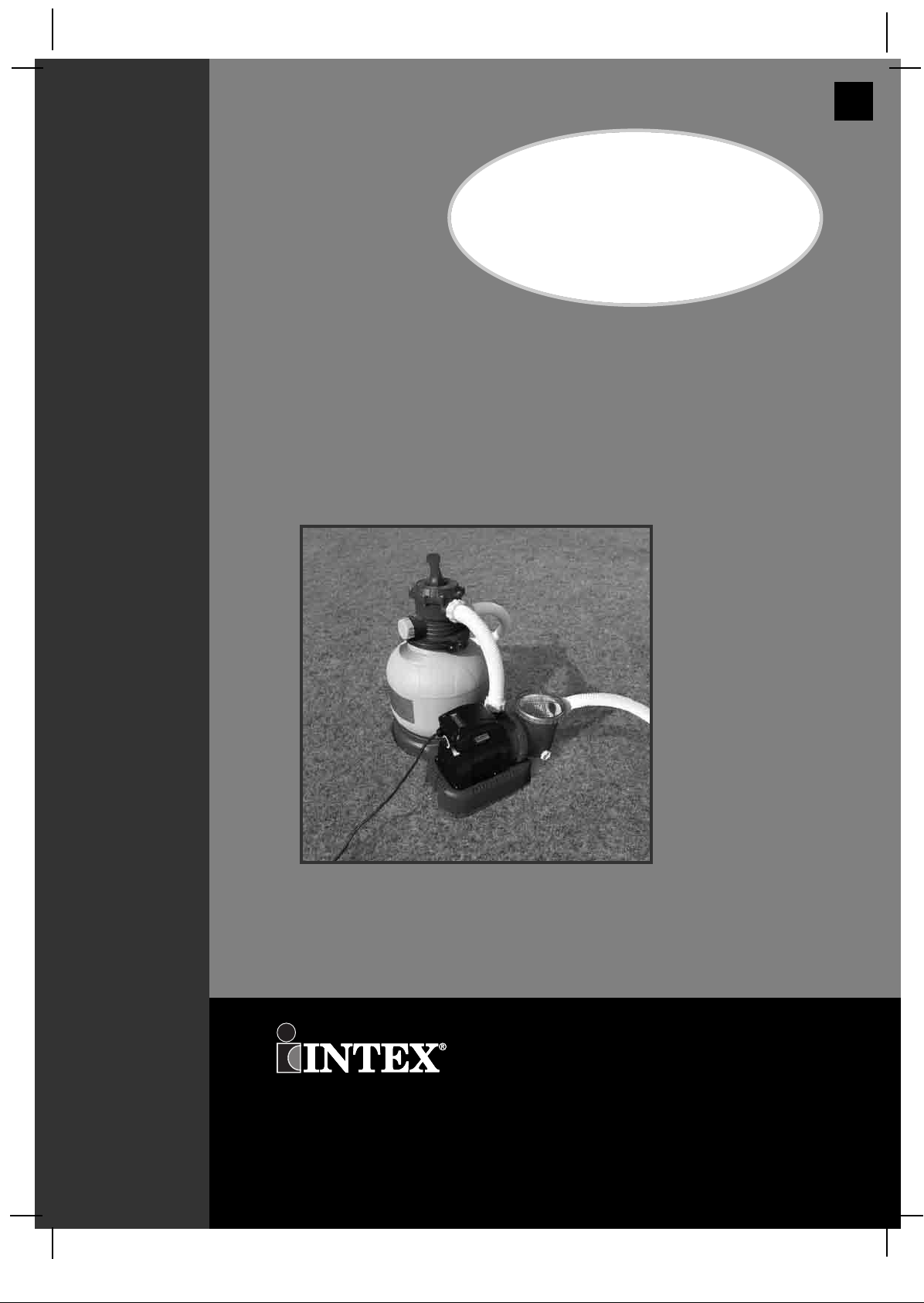
Krystal Clear
Sand Filter Pump
14” (360mm)
Model SF15220
English
162
OOWWNNEERR’’SS MMAANNUUAALL
For illustrative purposes only.
Don’t forget to try these other fine Intex products: pools, pool accessories,
inflatable pools and in-home toys, airbeds and boats available at fine
retailers or visit our website.
©2010 Intex Marketing Ltd. - Intex Development Co. Ltd. - Intex Trading Ltd.
- Intex Recreation Corp.
All rights reserved/Tous droits réservés/Todos los derechos reservados/Alle
Rechte vorbehalten. Printed in China/Imprimé en Chine/Impreso en China/Gedruckt in China.
®™ Trademarks used in some countries of the world under license from/®™ Marques utilisées dans certains pays sous
licence de/Marcas registradas utilizadas en algunos países del mundo bajo licencia de/Warenzeichen verwendet in einigen
Ländern der Welt in Lizenz von/Intex Marketing Ltd. to/à/a/an Intex Trading Ltd., Intex Development Co. Ltd., G.P.O
Box 28829, Hong Kong & Intex Recreation Corp., P.O. Box 1440, Long Beach, CA 90801 • Distributed in the European
Union by/Distribué dans lʼUnion Européenne par/Distribuido en la unión Europea por/Vertrieb in der Europäischen Union
durch/Intex Trading B.V., P.O. Box nr. 1075 – 4700 BB Roosendaal – The Netherlands
162**-A0-1109
Page 2
(162) MODEL SF15220 SAND FILTER PUMP ENGLISH 7.5” X 10.3” PANTONE 295U 09/28/2010
English
Warnings.......................................................................... 3
Parts List & References.................................................. 4-8
Setup Instructions ......................................................... 9-16
Product Specifications................................................... 11
Operating Instructions ................................................... 17-19
Intex Pools Operating Time Table.................................. 20-21
162
Non-Intex Pools Operating Time Table.......................... 22
Maintenance.................................................................... 23
Long Term Storage.......................................................... 24
Troubleshooting Guide................................................... 25
Common Pool Problems................................................. 26
General Aquatic Safety................................................... 27
Limited Warranty............................................................. 28
Intex Service Center Locations..................................... 29
TTAABBLLEE OOFF CCOONNTTEENNTTSS
SAVE THESE INSTRUCTIONS
Page 2
Page 3
(162) MODEL SF15220 SAND FILTER PUMP ENGLISH 7.5” X 10.3” PANTONE 295U 09/28/2010
English
IMPORTANT SAFETY RULES
Read, Understand and Follow All Instructions Carefully Before Installing and Using this Product.
READ AND FOLLOW ALL INSTRUCTIONS
WARNING
•
To reduce the risk of injury, do not permit children to use this product. Always
supervise children and those with disabilities.
•
Children must stay away from this product and electrical cord(s).
•
Children should be supervised to ensure that they do not play with the appliance.
•
This appliance is not intended for use by persons (including children) with reduced
physical, sensory or mental capabilities, or lack of experience and knowledge. They must
at all times be supervised by a knowledgeable and experienced adult responsible for their
safety.
•
Assembly and disassembly by adults only.
•
Risk of electric shock. Connect this product only to a grounding type receptacle protected
by a ground-fault circuit interrupter (GFCI) or residual current device (RCD). Contact a
qualified electrician if you cannot verify that the receptacle is protected by a GFCI/RCD.
Use a qualified electrician to install the GFCI/RCD, which has a maximum rate of 30mA.
Do not use a portable residual current device (PRCD).
•
Always unplug this product from the electrical outlet before removing, cleaning, servicing
or making any adjustment to the product.
•
The plug must be accessible after produc t is installed.
•
Do not bury the electrical cord. Locate the cord where it will not be damaged by lawn
mowers, hedge trimmers and other equipment.
•
If the supply cord is damaged, it must be replaced by the manufacturer, its service agent
or similarly qualified persons in order to avoid a hazard.
•
To reduce the risk of electric shock, do not use extension cords, timers, plug adaptors or
converter plugs to connect unit to electric supply; provide a properly located outlet.
•
Do not attempt to plug in or unplug this product while standing in water or when your
hands are wet.
•
Keep this product more than 2m away from the pool.
•
Keep this product more than 3.5m away from the pool (for France only).
•
Keep the plug of this product more than 3.5m away from the pool.
•
Position this product away from the pool, so as to prevent children from climbing on it and
accessing the pool.
•
Do not operate this product when pool is occupied.
•
This product is for use with storable pools only. Do not use with permanently installed
pools. A storable pool is constructed so that it may be readily disassembled for storage
and reassembled to its original configuration.
•
To reduce the risk of entrapment hazard, never enter the pool if suction strainer
component is loose, broken, cracked, damaged or missing. Replace loose, broken,
damaged, cracked or missing suction strainer components immediately.
•
Never play or swim near suction fittings. Your body or hair may be trapped causing
permanent injury or drowning.
•
To prevent equipment damage and risk of injury, always turn pump off before changing
the filter control valve position.
•
Never operate this product above the maximum working pressure stated on the filter tank.
•
Hazardous Pressure. Improper tank valve cover assembly could cause the valve cover to
blow off and cause serious injury, property damage or death.
•
This product is intended to be used only for the purposes described in the manual!
162
SSAAFFEETTYY RRUULLEESS
FAILURE TO FOLLOW THESE WARNINGS MAY RESULT IN
PROPERTY DAMAGE, ELECTRIC SHOCK, ENTANGLEMENT OR
OTHER SERIOUS INJURY OR DEATH.
These product warnings, instructions and safety rules provided with the product represent
some common risks of water recreation devices and do not cover all instances of risk and
danger. Please use common sense and good judgement when enjoying any water activity.
SAVE THESE INSTRUCTIONS
Page 3
Page 4
(162) MODEL SF15220 SAND FILTER PUMP ENGLISH 7.5” X 10.3” PANTONE 295U 09/28/2010
1
4 5
7
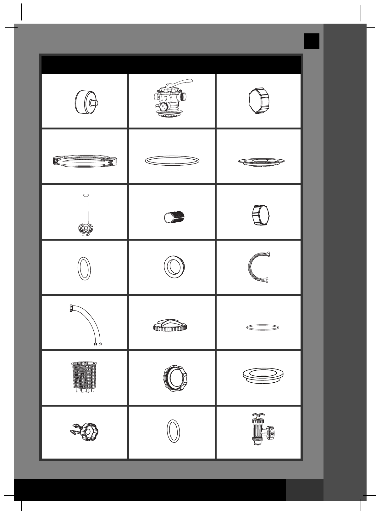
PARTS LIST
2
8
English
3
6
9
162
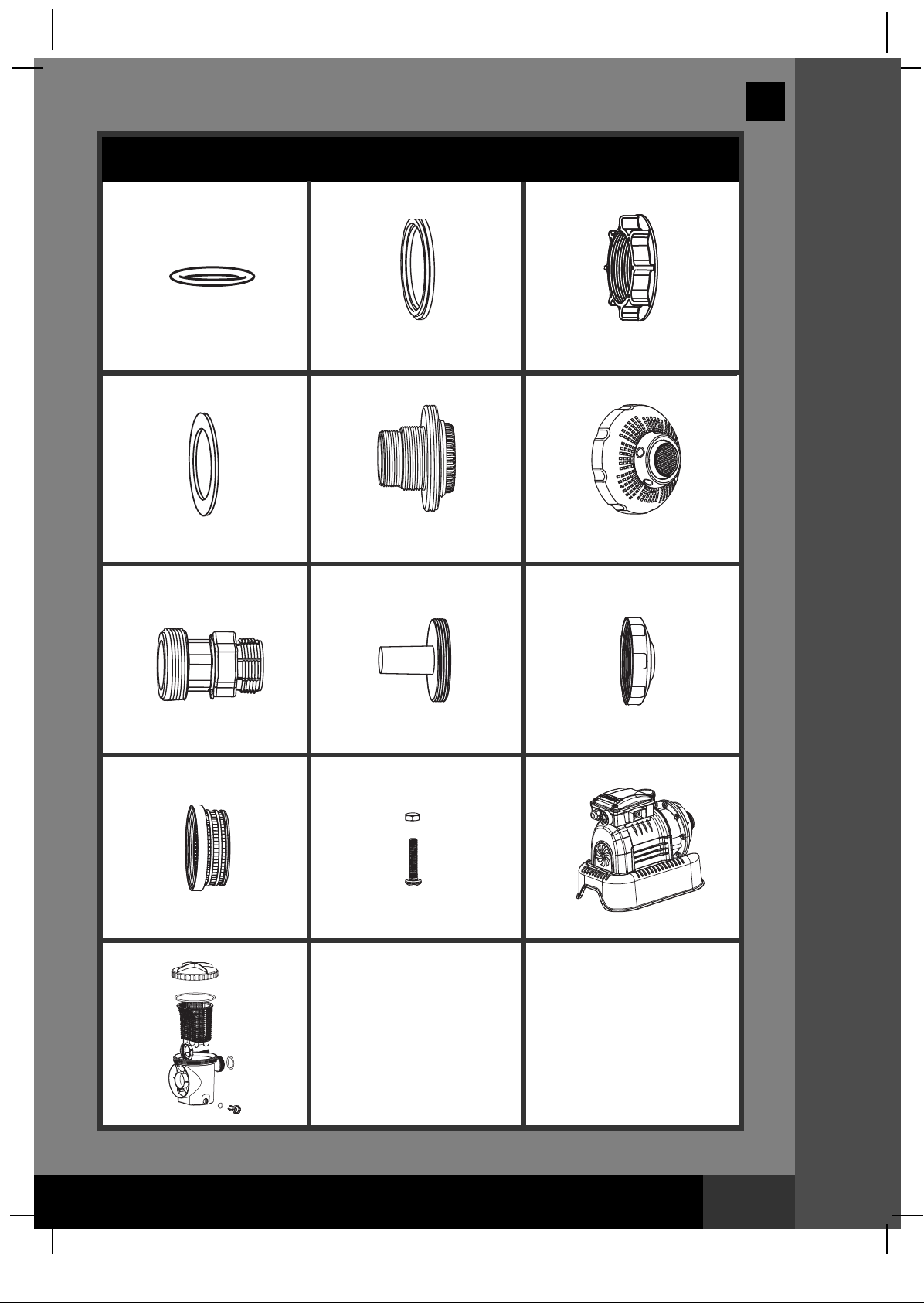
PPAARRTTSS LLIISSTT
10 11 12
13 14
16
17 18
20 2119
15
NOTE: Drawings for illustration purpose only. Actual product may vary. Not to scale.
SAVE THESE INSTRUCTIONS
Page 4
Page 5
(162) MODEL SF15220 SAND FILTER PUMP ENGLISH 7.5” X 10.3” PANTONE 295U 09/28/2010
PARTS LIST (continued)
22 24
25
23
26 27
English
162
PPAARRTTSS LLIISSTT
28 29 30
31
34
32
33
NOTE: Drawings for illustration purpose only. Actual product may vary. Not to scale.
SAVE THESE INSTRUCTIONS
Page 5
Page 6
(162) MODEL SF15220 SAND FILTER PUMP ENGLISH 7.5” X 10.3” PANTONE 295U 09/28/2010
English
162
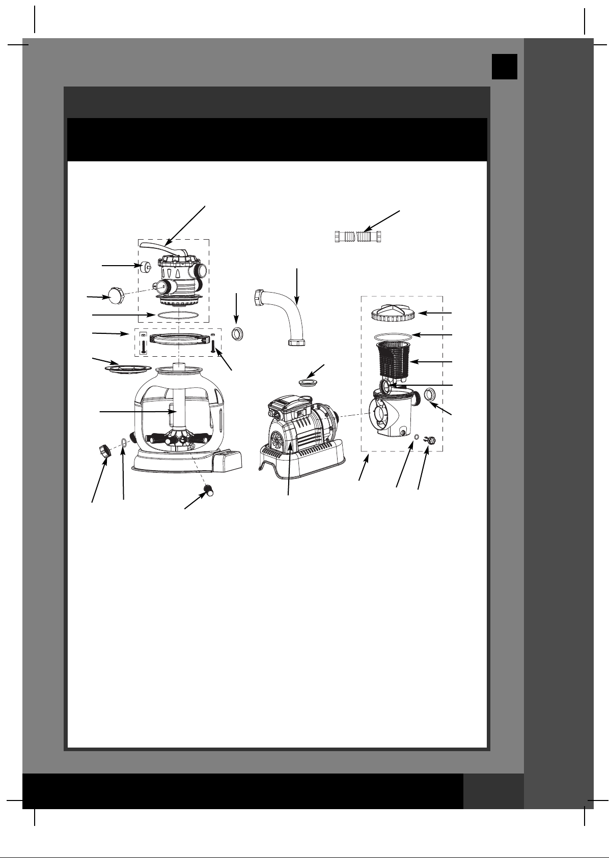
PARTS REFERENCE
Before assembling your product, please take a few minutes to check the contents
and become familiar with all the parts.
2
1
11
3
5
4
6
32
13
18
12
14
15
16
17
7
34
9
NOTE: Drawings for illustration purpose only. Actual product may vary. Not to scale.
10
8
33
20
19
11
PPAARRTTSS RREEFFEERREENNCCEE
SAVE THESE INSTRUCTIONS
Page 6
Page 7
(162) MODEL SF15220 SAND FILTER PUMP ENGLISH 7.5” X 10.3” PANTONE 295U 09/28/2010
PARTS REFERENCE (continued)
Before assembling your product, please take a few minutes to check the contents
and become familiar with all the parts.
23 24 25 26 27
21
22
23 24 25 26
English
162
21
22
PPAARRTTSS RREEFFEERREENNCCEE
23 28 29 30
21
22
23 28 29 31
21
22
NOTE: Drawings for illustration purpose only. Actual product may vary. Not to scale.
SAVE THESE INSTRUCTIONS
Page 7
Page 8
(162) MODEL SF15220 SAND FILTER PUMP ENGLISH 7.5” X 10.3” PANTONE 295U 09/28/2010
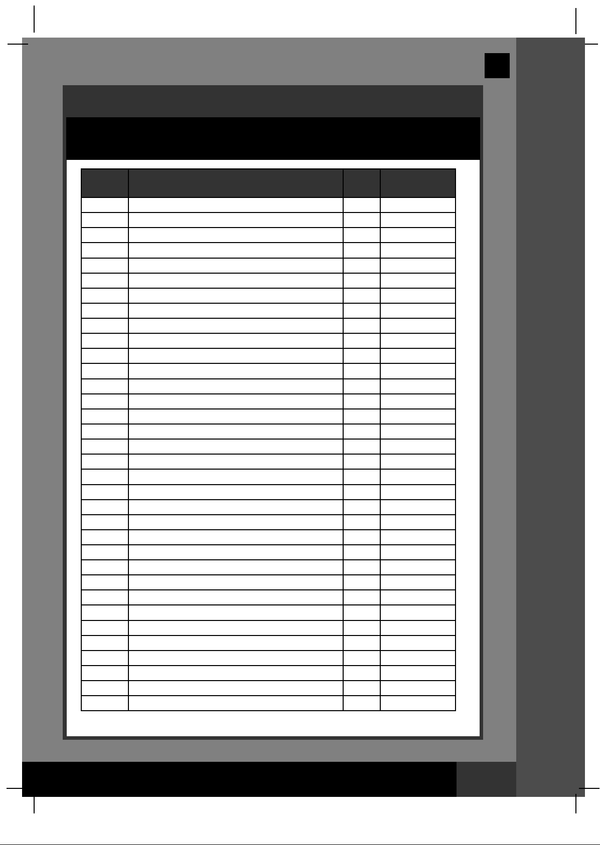
PARTS REFERENCE (continued)
Before assembling your product, please take a few minutes to check the contents
and become familiar with all the parts.
REF. NO. DESCRIPTION QTY.
1
2
3
4
5
6
7
8
9
10
11
12
13
14 LEAF TRAP COVER 1 11259
15 LEAF TRAP O-RING 1 11232
16 BASKET 1 11260
17 FILTER HOUSING NUT 1 11261
18
19 SEDIMENT RELEASE VALVE 1 10460
20 VALVE O-RING 1 10264
21
22
23
24
25
26
27
28
29
30
31
32
33
34
PRESSURE GAUGE
6-WAY VALVE
DRAIN OUTLET COVER
CLAMP
TANK O-RING
SAND SHIELD
CENTER PIPE HUB
LATERAL
DRAIN VALVE CAP
DRAIN VALVE O-RING
L-SHAPE O-RING
HOSE WITH NUTS
SAND FILTER INTERCONNECTING HOSE
L-SHAPE O-RING
PLUNGER VALVE (HOSE O-RING & STEP WASHER INCLUDED)
HOSE O-RING
STEP WASHER
STRAINER NUT
FLAT STRAINER RUBBER WASHER
THREADED STRAINER CONNECTOR
ADJUSTABLE POOL INLET NOZZLE
ADAPTOR B
STRAINER CONNECTOR
POOL INLET NOZZLE
STRAINER GRID
SCREW
PUMP MOTOR & CONTROL
PRE-FILTER ASSEMBLY
1 11411
1 11378
1 11131
1 11380
1 11379
1 11382
1 11383
10 11384
1
1 11385
4 11228
2 11010
1 11388
1 11412
2 10747
2 10262
2 10745
2 10256
2 10255
2 11235
1 11074
2 10722
2 11070
1 11071
1 11072
2 11381
1 11386
1 11371
SPARE PART
NO.
11226
English
162
PPAARRTTSS RREEFFEERREENNCCEE
When ordering parts, be sure to quote the model number and part numbers.
SAVE THESE INSTRUCTIONS
Page 8
Page 9
(162) MODEL SF15220 SAND FILTER PUMP ENGLISH 7.5” X 10.3” PANTONE 295U 09/28/2010
English
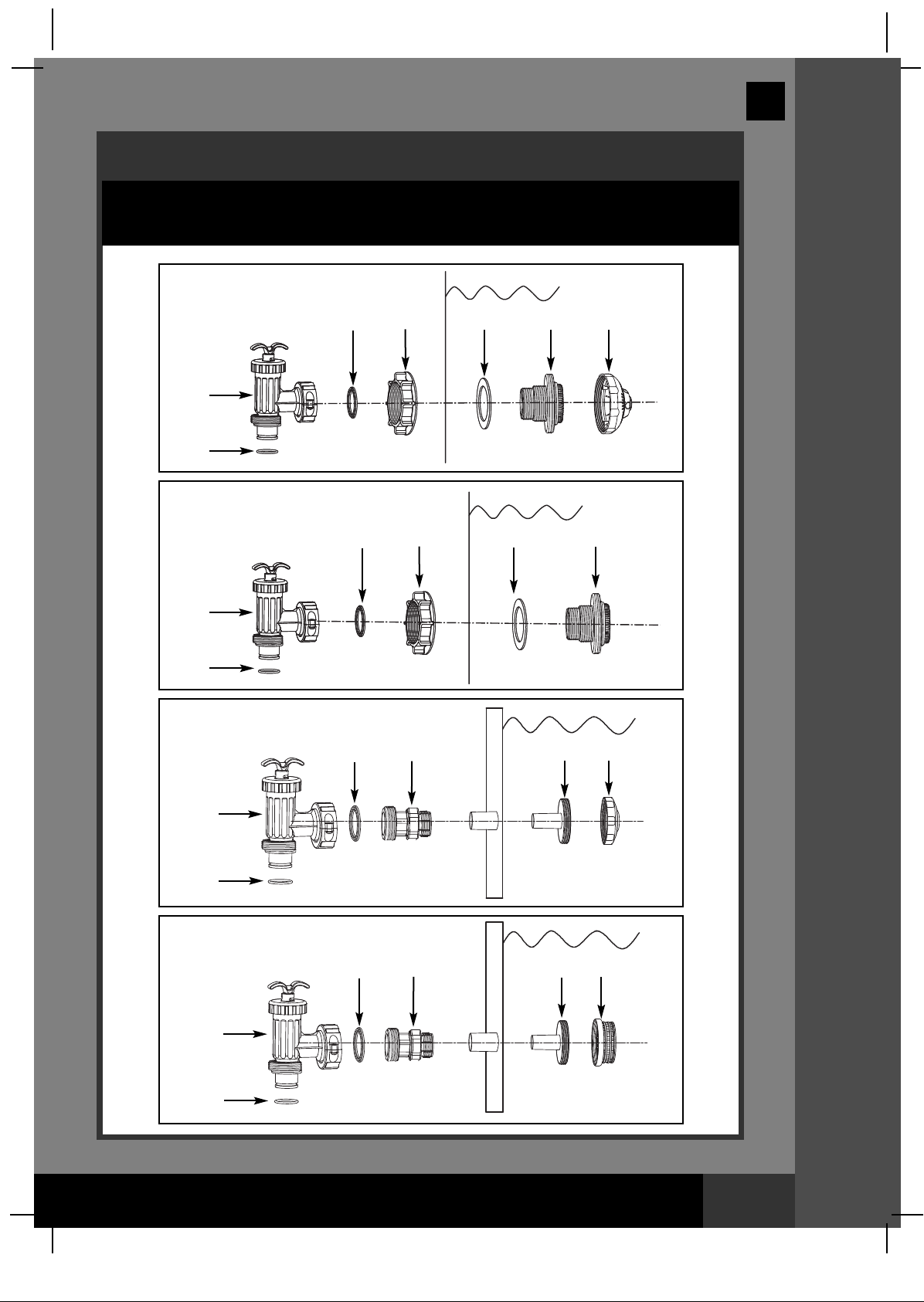
POOL OUTLET - STRAINER & PLUNGER VALVE SETUP
The strainer grid prevents large objects from jamming and/or damaging the
filter pump. If your pool has an inflatable top ring, install the strainer, nozzle
and plunger valve before inflating the pool liner top ring. The part numbers
here onward refer to the parts depicted in the Parts List section of this
manual. To install, do the following:
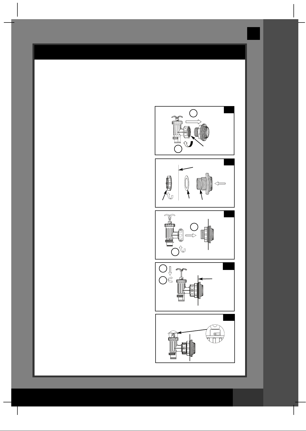
1. In a counter-clockwise motion unscrew
plunger valve union from the threaded
strainer connector (26) (see drawing 1).
Be careful not to lose the step rubber
washer (23). Place the plunger valve on
the ground in a safe place.
2. In a counter-clockwise motion unscrew the
strainer nut (24) from the threaded
connector (26). Leave the flat washer (25)
on the connector (26).
3. Install the strainer and plunger valve at the
lower position of pool outlet (marked "+").
From the inside of the pool liner insert the
connector (26) into one of the pre-cut holes
with the washer remaining on the
connector to be placed against the inside
of the liner wall.
4. Before assembly, lubricate the threads with
a petroleum jelly. With the flat side of the
strainer nut (24) facing the outside wall of
the liner in a clockwise motion screw the
strainer nut (24) back onto the threaded
connector (26) (see drawing 2).
5. Finger tighten the strainer nut (24) onto the
threaded connector (26).
6. Grasp the plunger valve assembly. Make
sure the step washer (23) is in place.
7. In a clockwise motion screw the plunger
valve union back onto the threaded
connector (26) (see drawing 3).
8. Examine the plunger valve to see if the
handle is pushed fully down to the "0/1"
position. If not, then grasp the handle at
the top and push down turning the handle
in a clockwise direction until the plastic
protruding notch anchors in the "0/1"
position. This will prevent water from
flowing out during filling (see
drawings 4.1 & 4.2).
24
2
1
2
2
1
25
23
INSIDE
LINER WALL
26
1
4.1
INSIDE
LINER WALL
162
1
2
3
SSEETTUUPP IINNSSTTRRUUCCTTIIOONNSS
4.2
SAVE THESE INSTRUCTIONS
Page 9
Page 10

(162) MODEL SF15220 SAND FILTER PUMP ENGLISH 7.5” X 10.3” PANTONE 295U 09/28/2010
POOL INLET - NOZZLE & PLUNGER VALVE SETUP
1. In a counter-clockwise motion unscrew
plunger valve union from the threaded
strainer connector (26) (see drawing 5).
Be careful not to lose the step rubber
washer (23). Place the plunger valve on
the ground in a safe place.
2. In a counter-clockwise motion unscrew the
strainer nut (24) from the threaded
connector (26). Leave the flat washer (25)
on the connector (26).
3. Install the nozzle and plunger valve at the
upper position of pool inlet. From the inside
of the pool liner insert the connector (26)
into one of the pre-cut holes with the
washer remaining on the connector to be
placed against the inside of the liner wall.
4. Before assembly, lubricate the threads with
a petroleum jelly. With the flat side of the
strainer nut (24) facing the outside wall of
the liner in a clockwise motion screw the
strainer nut (24) back onto the threaded
connector (26) (see drawing 6).
5. Finger tighten the adjustable pool inlet
nozzle (27) and the strainer nut (24) onto
the threaded connector (26).
6. Grasp the plunger valve assembly. Make
sure the step washer (23) is in place.
7. In a clockwise motion screw the plunger
valve union back onto the threaded
connector (26) (see drawing 7).
8. Examine the plunger valve to see if the
handle is pushed fully down to the "0/1"
position. If not, then grasp the handle at
the top and push down turning the handle
in a clockwise direction until the plastic
protruding notch anchors in the "0/1"
position. This will prevent water from
flowing out during filling (see
drawings 8.1 & 8.2).
9. Adjust the direction of nozzle head pointing
away from the pool outlet for a better
circulation result (see drawing 9).
10. The pool liner is now ready to fill with
water. Consult the above-ground-pool
ownerʼs manual for filling instructions.
24
English
2
1
INSIDE
LINER WALL
25 26 27
1
2
1
2
WATER
FLOW
5
6
7
8.1
INSIDE
LINER
WALL
8.2
9
162
SSEETTUUPP IINNSSTTRRUUCCTTIIOONNSS
SAVE THESE INSTRUCTIONS
POOL
Page 10
Page 11

(162) MODEL SF15220 SAND FILTER PUMP ENGLISH 7.5” X 10.3” PANTONE 295U 09/28/2010
English
PRODUCT SPECIFICATIONS
The sand filter removes suspended particles but does not sanitize your pool.
Pool chemistry is a specialized area and you should consult your local pool
service specialist for details.
Power: 220-240 Volt AC
Wattage: 370 W
Maximum working pressure: 2.4 bar (35 psi)
Effective filtering area: 0.1 m2(1.1 ft2)
Maximum Flow Rate: 6056 liters/hour (1600 gallons/hour)
Recommended filtering media:
(Not included) range 0.45 to 0.85 mm (0.018 to 0.033
Recommended filtering media quantity: 25 Kg (55 Lbs)
Limited Warranty: 2 Years (see “Limited Warranty”)
NOTE: NOT SUITABLE FOR USE WITH KCP-LOW -SALT AUTOMATIC SALTWATER
SYSTEM (MODEL 6110/6220
)
Use only No. 20 silica sand. Particle size
inches). Uniformity Coefficient less than 1.75.
SETUP INSTRUCTIONS
162
TOOLS REQUIRED: One (1) Phillips screwdriver
Pump location and mounting:
• The system must be installed on a solid level and vibration-free base.
• Provide a location protected from the weather, moisture, flooding and
freezing temperature.
• Provide adequate access, space and lighting for routine maintenance.
• Pump motor requires free circulation of air for cooling. Do not install
the pump in a damp or non-ventilated location.
A team of 2 or more people is recommended for setting up this product.
Motor pre-filtering assembly setup:
1. Remove the sand filter and its accessories
from the packaging carefully and inspect for
any visible damage. If parts are damaged
contact your local service center listed at
the back of this ownerʼs manual.
2. In a counter-clockwise motion unscrew the
leaf trap cover (14) from the pre-filter
housing. Take out the basket (16) and filter
housing nut (17) (see drawing 10).
Connect the pre-filter housing to the motor
3.
water inlet. Note: Align the connector in the
pre-filter housing with the water inlet on the
motor (see drawing 11).
14
17
16
10
11
SAVE THESE INSTRUCTIONS
PPRROODDUUCCTT SSPPEECCSS && SSEETTUUPP IINNSSTTRRUUCCTTIIOONNSS
Page 11
Page 12

(162) MODEL SF15220 SAND FILTER PUMP ENGLISH 7.5” X 10.3” PANTONE 295U 09/28/2010
mm
160
English
SETUP INSTRUCTIONS (continued)
4. In a clockwise motion screw filter housing nut (17) onto the motor water inlet
(See drawings 12.1 & 12.2).
12.1
17
5. Replace the basket (16) and leaf trap cover (14) back to the pre-filter housing
(See drawings 13.1 & 13.2).
14
16
13.1 13.2
12.2
17
162
Sand tank installation:
1. Place the tank support base at the selected location.
2. Place the tank on the tank support base (See drawing 14.1).
3. Connect the motor pre-filtering assembly unit to the tank support base (See
drawing 14.2). NOTE: Ensure the pre-filter housing water inlet hose connection
is facing towards the pool.
IMPORTANT: Some countries, especially in the European community,
require the product to be secured to the ground or to a base in a
permanent upright position. Check your local authorities to determine if
there is a regulation in your area regarding above-the-ground swimming
pool filter-pumps. If yes, then the product can be mounted to a platform
using the two holes located in the base. See drawing 14.3.
The product can be mounted on a cement base or onto a wooden
platform to prevent accidental falling over.
• The mounting holes are 6.4 mm in diameter and spaced 160 mm
apart.
• Use two bolts and lock nuts with a maximum of 6.4 mm in diameter.
14.1
14.2
SSEETTUUPP IINNSSTTRRUUCCTTIIOONNSS
14.3
SAVE THESE INSTRUCTIONS
Page 12
Page 13

(162) MODEL SF15220 SAND FILTER PUMP ENGLISH 7.5” X 10.3” PANTONE 295U 09/28/2010
MAX
MIN
MAXMAX
MINMIN
MAX
MIN
English
SETUP INSTRUCTIONS (continued)
Sand loading:
IMPORTANT: Use only No. 20 silica sand with particle size range 0.45 to 0.85
mm (0.018 to 0.033 inches) and a Uniformity Coefficient less than 1.75.
NOTE: Before loading the tank with sand, ensure the center pipe hub
assembly is securely in place at the bottom of the tank, and vertically
centered inside the tank.
1. Place the sand shield (6) over the top of the center pipe. Pour the sand into the
tank at a slow rate. (see drawing 15).
2. Fill the tank approximately half way, remove the sand shield (6) from the top.
(see drawing 16).
15
6
6
16
162
3. Evenly distribute the sand inside the tank, then fill the tank with some water to
provide a cushioning effect when the remaining sand is poured in. This
prevents the center pipe hub (7) from excessive shock (see drawing 17).
Place the sand shield (6) back and continue to pour the sand into the tank.
4. Sand shall be filled between the “MAX” and “MIN” marked gauge on the center
pipe. Evenly spread and level out the sand by hand (see drawings 17 & 18).
17
7
5. Remove the sand shield (6).
6. Wash away all sand around the top edge of the tank.
7
18
SSEETTUUPP IINNSSTTRRUUCCTTIIOONNSS
SAVE THESE INSTRUCTIONS
Page 13
Page 14

(162) MODEL SF15220 SAND FILTER PUMP ENGLISH 7.5” X 10.3” PANTONE 295U 09/28/2010
English
SETUP INSTRUCTIONS (continued)
WARNING
Improper tank valve and clamp assembly could cause the valve and clamp to blow
off and cause serious injury, property damage or death.
6-way valve installation:
1. Lower the 6-way valve over the tank slowly, and ensure the bypass pipe protruding
underneath the 6-way valve fits securely into the center pipe hub (7) top opening
drawing 19).
IMPORTANT: There are three hose connection ports on the 6-way valve,
ensure the outlet connection (from filter to the pool) on the valve is facing
towards the pool, and the inlet connection (from motor to valve) is aligned
with the motor outlet (see drawing 20).
19
WATER
INLET
(see
162
20
WATER
OUTLET
7
2. Place an L-shape o-ring (11) on the 6-way valve inlet connection and on the
pump motor outlet. In a clockwise motion connect the sand filter
interconnecting hose (13) between the pump motor outlet and the 6-way valve
inlet connection (see drawing 21).
3. Remove the clamp bolt, and install the clamp around the tank and 6-way valve
flanges, then replace the clamp bolt and use a phillips screwdriver (not
included) to tighten it (see drawing 22)
21
13
22
4
SSEETTUUPP IINNSSTTRRUUCCTTIIOONNSS
SAVE THESE INSTRUCTIONS
Page 14
Page 15

(162) MODEL SF15220 SAND FILTER PUMP ENGLISH 7.5” X 10.3” PANTONE 295U 09/28/2010
English
SAND FILTER PUMP HOSE CONNECTION SETUP
WARNING
• Keep this product more than 2m away from the pool.
• Keep this product more than 3.5m away from the pool (for France only).
• Keep the plug of this product more than 3.5m away from the pool.
• Position this product away from the pool, so as to prevent children from
climbing on it and accessing the pool.
The 6-way valve has three hose connection ports.
1. Connect one hose (12) end to the pre-filter inlet and the other end of the hose
to the lower plunger valve with the strainer. Ensure the hose nuts are securely
tightened.
2. Connect the second hose (12) between the 6-way valve water outlet and the
upper plunger valve with the inlet-nozzle. Ensure the hose nuts are securely
tighten.
3. The third hose connection port (drain/waste outlet) on the 6-way valve shall be
directed to a proper draining receptacle using a hose or pipe (not provided).
Remove the drain cap before attaching the drain/waste hose or pipe.
4. The sand filter pump is now ready to filter the pool.
162
WATER
INLET
TO
DRAIN
POWER
CORD
6-WAY VALVE
MOTOR
MOTOR
WATER
OUTLET
WATER
OUTLET
PRE-
FILTER
>3.5M
L-SHAPE
O-RING
WATER INLET
L-SHAPE
O-RING
PLUNGER
VALVE
>2M
WATER LEVEL
ADJUSTABLE
POOL INLET
NOZZLE
THREADED
STRAINER
CONNECTOR
OUTSIDE
LINER WALL
SSEETTUUPP IINNSSTTRRUUCCTTIIOONNSS
(ILLUSTRATION NOT TO SCALE)
SAVE THESE INSTRUCTIONS
Page 15
Page 16

(162) MODEL SF15220 SAND FILTER PUMP ENGLISH 7.5” X 10.3” PANTONE 295U 09/28/2010
English
SAND FILTER PUMP HOSE CONNECTION SETUP (continued)
For NON-INTEX pool:
Connect the hose (12) to the pool inlet/outlet connection with a large hose clamp.
Tighten securely. Remove the drain cap (3) before attaching the drain/waste
hose or pipe.
LARGE HOSE
CLAMP
12
POOL
3
162
For INTEX pool size 16' and below:
1. In a counter-clockwise motion unscrew plunger valve union from the threaded
strainer connector (26). Be careful not to lose the step rubber washer (23).
2. Grasp the plunger valve assembly. Make sure the step washer (23) is in place.
Connect adaptor B (28) to plunger valve union.
3. Remove wall plug and then insert the strainer (29 & 31) into the lower position
of protruding hose connection, and the nozzle (29 & 30) into the upper position
of protruding hose connection. Adaptor B (28) fits over the strainer
connection (29) inserted into the connection. Tighten securely.
4. Remove the drain cap (3) before attaching the drain/waste hose or pipe.
29 & 30
3
POOL
29 & 31
SSEETTUUPP IINNSSTTRRUUCCTTIIOONNSS
SAVE THESE INSTRUCTIONS
Page 16
Page 17

(162) MODEL SF15220 SAND FILTER PUMP ENGLISH 7.5” X 10.3” PANTONE 295U 09/28/2010
R
E
T
L
I
F
E
S
N
I
R
ET
A
L
U
C
RI
C
E
R
E
S
O
L
C
ETSA
W
E
S
N
I
R
ETALU
C
RICER
H
S
A
W
K
C
A
B
E
S
O
L
C
E
TSAW
R
E
T
L
I
F
E
S
N
I
R
E
TALU
C
RICER
H
S
A
W
K
C
A
B
ETSA
W
B
E
S
N
I
R
ETALU
C
RICER
H
S
A
W
K
C
A
B
E
S
O
L
C
E
TSAW
R
E
T
L
I
F
E
S
N
I
R
E
TALU
C
RICER
H
S
A
W
K
C
A
B
ETSA
W
R
E
T
L
I
F
E
S
N
I
R
E
TALU
C
RICER
H
S
A
W
K
C
A
B
ETSA
W
English
OPERATING INSTRUCTIONS
WARNING
• Risk of electric shock. Connect this product only to a grounding type
receptacle protected by a ground-fault circuit interrupter (GFCI) or
residual current device (RCD). Contact a qualified electrician if you cannot
verify that the receptacle is protected by a GFCI/RCD. Use a qualified
electrician to install the GFCI/RCD, which has a maximum rate of 30mA.
Do not use a portable residual current device (PRCD).
• To reduce the risk of electric shock, do not use extension cords, timers,
plug adaptors or converter plugs to connect unit to electric supply;
provide a properly located outlet.
• Do not attempt to plug in or unplug this product while standing in water
or when your hands are wet.
• Never operate this product above the maximum working pressure stated
on the filter tank.
• Always switch off pump before changing the 6-way valve position.
• Operating this product without water flowing through the system can
cause a build up of hazardous pressure which can result in an explosive
situation, serious injury, property damage or death.
• Never test this pump with compressed air. Never operate the system with
water temperature above 35° C (95° F).
162
6-way valve positions and function:
Valve Position Function Water Flow Direction
FILTER
(see drawing 24)
BACKWASH
(see drawing 25)
RINSE
(see drawing 26)
WASTE
(see drawing 27)
RECIRCULATE
(see drawing 28)
CLOSED
(see drawing 29)
Normal filtration and regular
vacuuming of pool
Reverses water flow to clean
filter media
For initial startup cleaning of the sand, and
leveling the sand bed after backwashing
For vacuuming directly to waste,
lowering pool level or to drain the pool
For circulating water back to pool
without going through the filter media
Shuts off all flow to filter and pool
“Do not use this setting with pump running”
24
From pump through filter media
to pool
From pump through filter media
to valve waste/drain outlet
From pump through filter media
to valve waste/drain outlet
From pump to valve waste/drain
outlet bypassing the filter media
From pump through valve to
pool bypassing the filter media
25
26
OOPPEERRAATTIINNGG IINNSSTTRRUUCCTTIIOONNSS
SAVE THESE INSTRUCTIONS
Page 17
Page 18

(162) MODEL SF15220 SAND FILTER PUMP ENGLISH 7.5” X 10.3” PANTONE 295U 09/28/2010
R
E
T
L
I
F
E
S
N
I
R
ET
A
L
U
C
RI
C
E
R
E
S
O
L
C
ETSA
W
E
S
N
I
R
ETALU
C
RICER
H
SA
W
K
C
A
B
E
S
O
L
C
E
TSAW
R
E
T
L
I
F
E
S
N
I
R
E
TALU
C
RICER
H
S
A
W
K
C
A
B
ETSA
W
R
E
T
L
I
F
E
S
N
I
R
ER
H
S
A
W
K
C
A
B
E
S
O
L
C
ETSAW
R
E
T
L
I
F
ES
N
I
R
E
TA
L
U
C
R
I
CE
R
H
S
A
W
K
C
A
B
E
S
O
L
C
R
E
T
L
I
F
ETALUC
R
ICER
H
S
A
W
K
C
A
B
E
S
O
L
C
ETSAW
B
E
S
N
I
R
ETALU
C
RICER
H
SA
W
K
C
A
B
E
S
O
L
C
E
TSAW
R
E
T
L
I
F
E
S
N
I
R
E
TALU
C
RICER
H
S
A
W
K
C
A
B
ETSA
W
R
E
T
L
I
F
ES
N
I
R
E
TA
L
U
C
R
I
CE
R
H
S
A
W
K
C
A
B
E
S
O
L
C
R
E
T
L
I
F
ETALUC
R
ICER
H
S
A
W
K
C
A
B
E
S
O
L
C
ETSAW
R
E
T
L
I
F
E
S
N
I
R
E
TALU
C
RICER
H
S
A
W
K
C
A
B
ETSA
W
R
E
T
L
I
F
ETALUC
R
ICER
H
S
A
W
K
C
A
B
E
S
O
L
C
ETSAW
English
OPERATING INSTRUCTIONS (continued)
27
Initial startup and operation:
Before operating, be sure that:
• All the hoses have been connected and tightened securely, and correct amount
of filter sand have been loaded.
• The entire system is connected to a grounding type receptacle protected by a
ground-fault circuit interrupter (GFCI) or residual current device (RCD).
28
CAUTION
162
29
The filter control valve has a closed position. The pump should never be
on when the valve is in the closed position. If the pump is operated with
the valve closed, explosive situation could exist.
1. Grasp plunger valve handle. Turn the handle counter-clockwise, pull up until it
stops, and then turn it clockwise until the metal protruding notch anchor is in
the "0/1" position. Repeat for the second plunger valve. This opens the valves to
allow water to flow into the sand filter pump.
2. Ensure the drain/waste outlet on the 6-way valve is not covered and directed to
a proper draining receptacle.
3. Ensure the pump is off, depress the 6-way
30
valve and turn it to the “BACKWASH” position
(see drawings 25 & 30).
IMPORTANT: To prevent damage to the
2
1
6-way valve, always depress the valve
handle before turning. Always switch off
pump before changing the 6-way valve
position.
4. Switch on the pump (see drawing 31). Water
is circulating backward through the sand
media and to waste/drain outlet. Backwash
until a clear flow of water is observed in the
waste/drain outlet or through the drain sediment
31
OOPPEERRAATTIINNGG IINNSSTTRRUUCCTTIIOONNSS
window.
NOTE: The initial backwash of the filter is
recommended to remove any impurities or fine
TIMER
OFF
ON
sand particles in the sand media.
SAVE THESE INSTRUCTIONS
Page 18
Page 19

(162) MODEL SF15220 SAND FILTER PUMP ENGLISH 7.5” X 10.3” PANTONE 295U 09/28/2010
English
OPERATING INSTRUCTIONS (continued)
5. Switch off the pump, change the 6-way valve to “RINSE” position (see
drawing 26).
6. Switch on the pump and run the pump for about one minute to level out the
sand bed after backwashing the sand media.
7. Switch off the pump, change the 6-way valve to “FILTER” position (see
drawing 24).
8. Switch on the pump. The system is now operating in the normal filtering mode.
Run the pump until the desired pool water clearance is obtained and no more
than 12 hours per day.
9. Record the initial pressure gauge reading when the filter media is clean.
NOTE: During initial setup of the system, it may be necessary to backwash
frequently due to unusual heavy dirt present in the water and sand. After that,
as the filter removes dirt and impurities from the pool water, the accumulated
dirt in the sand media will cause the pressure to rise and the flow to diminish. If
there is no vacuuming device attached to the system and the pressure gauge
reading is in the yellow zone it is time to backwash the sand media, see
“BACKWASH” under “initial startup and operation” section.
Vacuuming device (i.e. Intex auto pool cleaner) attached to the system may also
cause the flow to diminish and the pressure to rise. Remove any vacuuming
device from the system and check if the pressure gauge reading has dropped
from the yellow zone to the green zone.
162
Operating the system under “TIMER” mode or manually:
To operate the sand filter pump in “FILTER” mode under “TIMER” control:
A. Set the timer dial to the desired operating hours. See operation time table
(see drawing 32).
B. Turn on the pump by pressing the switch to “ ” position, the sand filter
pump is now filtering the water and will stop after the operating hours are
completed. The built-in timer will now operate for the number of hours
selected at the same time each day.
C. Operating hours can be re-adjusted if necessary. Follow step A – B.
To operate the sand filter pump manually (without the “TIMER” mode):
A. Turn on the pump by pressing the switch to “-” position, the sand filter
pump is now filtering the water.
B. To turn off the pump, press the switch to “O” position.
32
OOPPEERRAATTIINNGG IINNSSTTRRUUCCTTIIOONNSS
TIMER DIAL
(HOURS)
TIMER
OFF
ON
SAVE THESE INSTRUCTIONS
Page 19
Page 20

(162) MODEL SF15220 SAND FILTER PUMP ENGLISH 7.5” X 10.3” PANTONE 295U 09/28/2010
English
INTEX POOLS OPERATING TIME TABLE (WITHOUT INTEX SALTWATER SYSTEM)
This table shows the required operating time for average use of the sand filter pump with
above ground pools.
Pool Size
INTEX ABOVE GROUND POOLS (AGPʼs)
15' x 33" (457cm x 84cm)
15' x 36" (457cm x 91cm)
15' x 42" (457cm x 107cm)
EASY SET
POOL
ROUND
METAL
FRAME POOL
ULTRA FRAME
POOL
SEQUOIA SPIRIT
POOL SET
OVAL FRAME
POOL
RECT. ULTRA
FRAME POOL
®
®
15' x 48" (457cm x 122cm)
16' x 42"(488cm x 107cm)
16' x 48" (488cm x 122cm)
18' x 42" (549cm x 107cm)
18' x 48" (549cm x 122cm)
18' x 52" (549cm x 132cm)
15' x 36" (457cm x 91cm)
15' x 42" (457cm x 107cm)
15' x 48" (457cm x 122cm)
16' x 48" (488cm x 122cm)
18' x 48" (549cm x 122cm)
18' x 52" (549cm x 132cm)
24' x 48" (732cm x 122cm)
24' x 52" (732cm x 132cm)
16' x 48" (488cm x 122cm)
18' x 52" (549cm x 132cm)
16'8" x 49" (508cm x 124cm)
18'8" x 53" (569cm x 135cm)
18' x 10' x 42" (549cm x 305cm x 107cm)
20' x 12' x 48" (610cm x 366cm x 122cm)
24' x 12' x 48" (732cm x 366cm x 122cm)
28' x 12' x 48" (853cm x 366cm x 122cm)
18' x 9' x 52" (549cm x 274cm x 132cm)
24' x 12' x 52" (732cm x 366cm x 132cm)
32' x 16' x 52" (975cm x 488cm x 132cm)
Water Capacity (Calculated at
90% for Frame Pool and 80% for
Easy Set & Oval Pool)
(Gals) (Liters) (Hours)
2587
2822
3284
3736
3754
4273
4786
5455
5894
3282
3861
4440
5061
6423
6981
11483
12481
5061
6981
5061
6981
2885
4393
5407
6420
4545
8403
14364
9792
10681
12430
14141
14209
16173
18115
20647
22309
12422
14614
16805
19156
24311
26423
43463
47241
19156
26423
19156
26423
10920
16628
20465
24300
17203
31805
54368
Sand filter pump
operating time
(For one cycle)
2
2
2
2
2
4
4
4
4
2
2
4
4
4
4
8
8
2
4
2
4
2
4
4
4
4
6
12
162
SAVE THESE INSTRUCTIONS
Page 20
Page 21

(162) MODEL SF15220 SAND FILTER PUMP ENGLISH 7.5” X 10.3” PANTONE 295U 09/28/2010
English
INTEX POOLS OPERATING TIME TABLE (WITH INTEX SALTWATER SYSTEM)
If the system is attached to an “Intex Saltwater System” unit, the filter pump running time
should be longer than the required operating time of the Intex Saltwater System unit.
Water Capacity (Calculated at
90% for Frame Pool and 80%
Pool Size
INTEX ABOVE GROUND POOLS (AGPʼs)
15' x 33" (457cm x 84cm)
15' x 36" (457cm x 91cm)
15' x 42" (457cm x 107cm)
EASY SET
POOL
CIRCULAR
METAL
FRAME POOL
ULTRA FRAME
POOL
SEQUOIA SPIRIT
POOL SET
OVAL FRAME
POOL
RECT. ULTRA
FRAME POOL
®
®
15' x 48" (457cm x 122cm)
16' x 42" (488cm x 107cm)
16' x 48" (488cm x 122cm)
18' x 42" (549cm x 107cm)
18' x 48" (549cm x 122cm)
18' x 52" (549cm x 132cm)
15' x 36" (457cm x 91cm)
15' x 42" (457cm x 107cm)
15' x 48" (457cm x 122cm)
16' x 48" (488cm x 122cm)
18' x 48" (549cm x 122cm)
18' x 52" (549cm x 132cm)
20' x 52" (610cm x 132cm)
24' x 48" (732cm x 122cm)
24' x 52" (732cm x 132cm)
16' x 48" (488cm x 122cm)
18' x 52" (549cm x 132cm)
16'8" x 49" (508cm x 124cm)
569
18'8" x 53" (
18' x 10' x 42" (549cm x 305cm x 107cm)
20' x 12' x 48" (610cm x 366cm x 122cm)
24' x 12' x 48" (732cm x 366cm x 122cm)
28' x 12' x 48" (853cm x 366cm x 122cm)
18' x 9' x 52" (549cm x 274cm x 132cm)
24' x 12' x 52" (732cm x 366cm x 132cm)
32' x 16' x 52" (975cm x 488cm x 132cm)
cm x 135cm)
for Easy Set & Oval Pool)
(Gals) (Liters)
2587
2822
3284
3736
3754
4273
4786
5455
5894
3282
3 861
4440
5061
6423
6981
8638
11483
12481
5061
6981
5061
6981
2885
4393
5407
6420
4545
8403
14364
9792
10681
12430
14141
14209
16173
18115
20647
22309
12422
14614
16805
19156
24311
26423
32695
43462
47241
19156
26423
19156
26423
10920
16628
20465
24300
17203
31805
54368
NOTE: The “12” hours timer setting position has an additional 20 minutes over the actual
setting.
Saltwater System
operating Time (with
cyanuric acid 30-50ppm) (hours)
10 - 19°C
(50 - 66°F)
1
1
1
1
1
2
2
2
2
1
1
2
2
2
2
3
4
5
2
2
2
2
1
2
2
2
2
3
6
20 - 28 °C
(68 - 82 °F)
1
1
1
2
2
2
2
2
2
1
2
2
2
2
2
3
4
5
2
2
2
2
1
2
2
2
2
3
6
29 - 36 °C
(84 - 97 °F)
1
1
2
2
2
2
2
3
3
2
2
2
2
3
3
4
5
6
2
3
2
3
1
2
3
3
2
4
7
Sand Filter
Pump
Operating
Time
(hours)
4
4
4
4
4
6
6
6
6
4
4
6
6
6
8
8
12
12
6
8
6
8
4
6
6
6
6
8
12
162
SAVE THESE INSTRUCTIONS
Page 21
Page 22

(162) MODEL SF15220 SAND FILTER PUMP ENGLISH 7.5” X 10.3” PANTONE 295U 09/28/2010
English
NON-INTEX POOLS OPERATING TIME TABLE
This table shows the required operating time for average use of the sand filter pump with
above ground pools.
Water Capacity
(Gals) (Liters) (Hours)
3000
4000
5000
6000
7000
8000
9000
10000
11000
12000
13000
14000
15000
16000
17000
18000
19000
11355
15140
18925
22710
26495
30280
34065
37850
41635
45420
49205
52990
56775
60560
64345
68130
71915
Sand filter pump operating
time (For one cycle)
2
4
4
4
4
6
6
6
6
8
8
8
12
12
12
12
12
162
SAVE THESE INSTRUCTIONS
Page 22
Page 23

(162) MODEL SF15220 SAND FILTER PUMP ENGLISH 7.5” X 10.3” PANTONE 295U 09/28/2010
1
2
English
MOTOR PRE-FILTER CLEANING AND MAINTENANCE
1. Make sure the filter pump is switched off, then disconnect the power cord from
the electrical outlet.
2. Grasp a plunger valve handle. Turn the handle counter-clockwise, push down
until it stops and then turn it clockwise until the plastic protruding notch anchors
in the "0/1" position. Repeat for the second plunger valve. This prevents the
water from flowing out of the pool.
3. Release the pressure first by opening the
sediment release valve (19) located
on the lower side of the pre-filter housing
(see drawing 33).
33
19
162
4. In a counter-clockwise motion unscrew the
leaf trap cover (14), then remove the
basket (16) and leaf trap o-ring (15) from the
pre-filter housing (see drawing 34).
5. Empty and flush the basket using a garden hose, may use a plastic brush to
remove deposits from the basket. Do not use metal brush.
6. Clean and rinse the inside of the pre-filter housing and the leaf trap O-ring with
a garden hose.
7. Reinstall the leaf trap O-ring, basket and leaf trap cover to the pre-filter housing.
8. Close the sediment release valve (19).
34
14
16
15
MMAAIINNTTEENNAANNCCEE
SAVE THESE INSTRUCTIONS
Page 23
Page 24

(162) MODEL SF15220 SAND FILTER PUMP ENGLISH 7.5” X 10.3” PANTONE 295U 09/28/2010
English
POOL CARE & CHEMICALS
• All pools require care to keep the water clear and hygienically clean. With proper
chemical control, your filter will help attain this objective. Consult your pool supply dealer
for instructions regarding the proper use of chlorine, algaecide and other chemical
agents required for sparkling clear water.
• Keep pool chemicals away from children.
• Do not replenish chemicals in pool while pool is occupied. Skin or eye irritations could
occur.
• Daily pH checking and chemical treatment of the water is very important and cannot be
overemphasized. Chlorine, algaecide and maintenance of proper pH levels are required
when filling the pool as well as during the season. Consult your local swimming pool
supply store for instructions.
• The season's first filling of the pool may have brackish water requiring extra water
additives and extra filtering time. Do not allow swimming in pool until the pH level is
balanced. Consult your local swimming pool supply store for instructions.
• Chlorinated water may damage lawns, gardens or shrubbery as children play in the pool
and splash water outside the pool. Lawn areas underneath the pool liner will be
destroyed. Note that some types of grass may grow through the liner.
• Filter run time depends on pool size, weather and usage level. Experiment with various
run times so as to produce clean clear water.
CAUTION
Concentrated chlorine solutions may damage the pool liner. Always follow the
chemical manufacturerʼs directions, and the health and hazard warnings.
LONG TERM STORAGE & WINTERIZATION
162
MMAAIINNTTEENNAANNCCEE
CAUTION
Allowing the water to freeze will damage the sand filter and void the warranty.
If anti-freeze solution is needed, use only propylene glycol. Propylene glycol
is non-toxic and will not damage plastic system components; other antifreezes are highly toxic and may damage plastic components in the system.
1. Before emptying your pool for long term storage, or relocation, be sure the water is
directed towards an acceptable drain water receptacle away from the house. Check local
regulations for specific directions regarding disposal of swimming pool water.
2. Switch off the unit, and disconnect power cord from electrical outlet.
3. When the pool is empty, disconnect all hoses from pump and plunger valves and
remove the strainers/plunger valves from the pool wall.
4. In a counter clockwise motion unscrew the drain valve cap (9) from the drain valve to
thoroughly drain the tank. The drain valve is located at the bottom of the filter tank.
5. Disassemble the pump motor from the tank base.
6. Leave sand filter pump pieces and hoses outside to thoroughly air dry.
7. Coat the following o-rings and washers with petroleum jelly for long term storage:
• L-shape o-ring (11).
• o-ring A (18).
• Pump hose O-rings (22).
• Strainer valve assembly step washers (23).
• Flat strainer rubber washers (25).
8. Depress the 6-way valve handle and rotate so as to set the pointer on the valve top
“N” position. This allows the water to drain from the valve. Leave the 6-way valve in this
inactive position.
9.
It is best to place all dry pieces and pump motor in the original packaging for storage. To
avoid condensation or corrosion problem, do not cover or wrap pump motor with plastic bags.
10. Store the pump motor and accessories in a dry place. The storage's temperature
should be controlled, between 0 degrees Celsius (32 degrees Fahrenheit) and 40
degrees Celsius (104 degrees Fahrenheit).
SAVE THESE INSTRUCTIONS
Page 24
Page 25

(162) MODEL SF15220 SAND FILTER PUMP ENGLISH 7.5” X 10.3” PANTONE 295U 09/28/2010
TROUBLESHOOTING GUIDE
TROUBLE CAUSE SOLUTION
FILTER MOTOR
FAILS TO START
FILTER DOESNʼT
CLEAN POOL
FILTER DOESNʼT
PUMP WATER OR
FLOW IS VERY
SLOW
• The motor is not plugged in.
• The fuse box needs checking.
• The GFCI/RCD circuit breaker
is tripped.
• Motor too hot and overload
protection is shut off.
• Improper chlorine or pH
levels.
• No filtering media in tank.
• Wrong 6-way valve setting
position.
• Excessively dirty pool.
• The strainer screen is
restricting the water flow.
• Clogged inlet or discharge.
• An air leak on the intake line.
• Excessively dirty pool.
• Sand media clogged with dirt.
• Nozzle and strainer
connections are reversed.
• Crusting or caking on the
filtering sand surface.
• Pool vacuuming device
attached to the system.
• Line cord must be plugged into a 3
wire outlet that is protected by a Class
A Ground Fault Circuit Interrupter, or
RCD.
• Reset circuit breaker. If circuit breaker
trips repeatedly, your electrical system
may have a defect. Turn off circuit
breaker and call an electrician to
correct the problem.
•
Let the motor cool down and restart again.
• Adjust
• Load with filter sand, see “sand loading
• Set valve to “ FILTER” position.
• Operate
• Clean
• Clear any obstructions in the intake
• Tighten hose nuts, check hoses for
• Clean the pre-filtering basket more often.
• Backwash filter.
• Install the nozzle at the upper position
• Remove about 1” of sand if necessary.
• Remove any pool vacuuming device
the
your local swimming pool supply stores.
instructions”.
hose by discharging it inside pool wall.
damage, check pool water level.
of the pool inlet, and the strainer at the
lower position of the pool outlet.
attached to the system line.
chlorine and pH level. Consult
the
the
strainer screen at the inlet.
English
filter for longer periods.
162
PUMP DOESNʼT
WORK
6-WAY
VALVE/COVER
LEAKING
HOSE LEAKING
TIMER IS
INACCURATE OR
TIMER CAN'T BE
SET
PRESSURE GAUGE
DOESNʼT WORK
SAND IS FLOWING
BACK INTO THE
POOL
• Low water level.
• Strainer screen clogged up.
• An air leak on the intake hose.
• Faulty motor or the impeller
is jammed.
• Sand tank o-ring missing.
• Sand tank o-ring dirty.
• Flange clamp not tight.
• 6-way valve damage.
• Hose nut not securely tight.
• Hose connection fitting
o-ring/L-shape o-ring missing.
• Possible inner timer
defective.
• Clogged inlet of the pressure
gauge.
• Pressure gauge damage.
• Sand is too small.
• Sand bed is calcified.
• Fill pool to correct water level.
• Clean strainer screens at pool inlet.
• Tighten hose nuts, check hose for
damage.
• Contact Intex service center.
•
Remove 6-way valve cover and ensure the
o-ring is in place.
•
Clean sand tank o-ring with garden hose water.
•
Tighten the clamp with wrench supplied.
•
Contact Intex service center.
• Tighten/reinstall hose nut.
• Ensure o-ring/L-shape o-ring is in place
and not damaged.
• Turn off the pump and restart 5 minutes
later.
• Re-set the timer.
• Contact Intex service center.
• Clear any obstructions in the intake by
unscrewing it from the 6-way valve.
• Contact Intex service center.
• Use only No. 20 silica sand with particle
size range 0.45 to 0.85 mm (0.018
to 0.033 inches) and a Uniformity
Coefficient less than 1.75.
• Change sand.
TTRROOUUBBLLEESSHHOOOOTTIINNGG GGUUIIDDEE
SAVE THESE INSTRUCTIONS
Page 25
Page 26

(162) MODEL SF15220 SAND FILTER PUMP ENGLISH 7.5” X 10.3” PANTONE 295U 09/28/2010
COMMON POOL PROBLEMS
PROBLEM DESCRIPTION CAUSE SOLUTION
ALGAE
COLORED
WATER
FLOATING
MATTER IN
WATER
• Greenish water.
• Green or black
spots on pool liner.
• Pool liner is
slippery and/or has
a bad odor.
• Water turns blue,
brown, or black
when first treated
with chlorine.
• Water is cloudy or
milky.
• Chlorine and pH levels
need adjustment.
• Copper, iron or
maganese in water
being oxidized by the
added chlorine.
This is Common.
• "Hard water" caused
by a too high pH level.
• Chlorine content is low.
• Foreign matter in
water.
• Super chlorinate with shock
treatment. Correct pH to your
pool store's recommended
level.
• Vacuum pool bottom.
• Maintain proper chlorine
level.
• Adjust pH level to the
recommended level.
• Run filter until water is clear.
• Correct the pH level. Check
with your pool dealer for
advice.
• Adjust the chlorine level.
English
162
CHRONIC
LOW WATER
LEVEL
SEDIMENT
ON POOL
BOTTOM
SURFACE
DEBRIS
• Level is lower than
on previous day.
• Dirt or sand on
pool floor.
• Leaves, insects
etc.
• Rip or hole in pool
liner or hoses.
• The drain valves are
loose.
• Heavy use, getting in
and out of pool.
• Pool too close to
trees.
• Repair with a patch kit.
• Finger tighten all caps.
• Use Intex pool vacuum to
clean bottom of pool.
• Use Intex pool skimmer.
IMPORTANT
If you continue to experience difficulty, please contact our Consumer
Service Department for assistance. See back cover for contact information.
CCOOMMMMOONN PPRROOBBLLEEMMSS
SAVE THESE INSTRUCTIONS
Page 26
Page 27

(162) MODEL SF15220 SAND FILTER PUMP ENGLISH 7.5” X 10.3” PANTONE 295U 09/28/2010
English
GENERAL AQUATIC SAFETY
Water recreation is both fun and therapeutic. However, it involves
inherent risks of injury and death. To reduce your risk of injury, read
and follow all product, package and package insert warnings and
instructions. Remember, however, that product warnings, instructions
and safety guidelines cover some common risks of water recreation,
but do not cover all risks and or dangers.
For additional safeguards, also familiarize yourself with the following
general guidelines as well as guidelines provided by nationally
recognized Safety Organizations:
• Demand constant supervision. A competent adult should be appointed as
a “lifeguard” or water watcher, especially when children are in and around
the pool.
• Learn to swim.
• Take the time to learn CPR and first aid.
• Instruct anyone who is supervising pool users about potential pool
hazards and about the use of protective devices such as locked doors,
barriers, etc.
• Instruct all pool users, including children what to do in case of an
emergency.
• Always use common sense and good judgement when enjoying any
water activity.
• Supervise, supervise, supervise.
162
SSAAFFEETTYY GGUUIIDDEELLIINNEESS
SAVE THESE INSTRUCTIONS
Page 27
Page 28

(162) MODEL SF15220 SAND FILTER PUMP ENGLISH 7.5” X 10.3” PANTONE 295U 09/28/2010
English
LIMITED WARRANTY
Your Sand Filter Pump has been manufactured using the highest quality materials and
workmanship. All Intex products have been inspected and found free of defects prior to
leaving the factory. This Limited Warranty applies only to the Sand Filter Pump.
The following provision is only valid within the European member states countries: The
legal regulation of Directive 1999/44/EC will not be effected by this Intex warranty.
The provisions of this Limited Warranty apply only to the original purchaser and is not
transferable. This Limited Warranty is valid for a period of two (2) years from the date of
the initial retail purchase. Keep your original sales receipt with this manual, as proof of
purchase will be required and must accompany warranty claims or the Limited Warranty
is invalid.
If a manufacturing defect is found within this two (2) years period, please contact the
appropriate Intex Service Center listed in this manual. The Service Center will determine
the validity of the claim.
162
IMPLIED WARRANTIES ARE LIMITED TO THE TERMS OF THIS WARRANTY AND IN
NO EVENT SHALL INTEX, THEIR AUTHORIZED AGENTS OR EMPLOYEES BE
LIABLE TO THE BUYER OR ANY OTHER PARTY FOR DIRECT OR CONSEQUENTIAL
DAMAGES OR LIABILITIES. Some countries, or jurisdictions do not allow the exclusion
or limitation of incidental or consequential damages, so the above limitation or exclusion
may not apply to you.
This Limited Warranty does not apply if the Sand Filter Pump is subject to negligence,
abnormal use or operation, accident, improper operation, improper voltage or current
contrary to operating instructions, or to damage by circumstances beyond Intexʼs control,
including but not limited to, ordinary wear and tear and damage caused by exposure to
fire, flood, freezing, rain, or other external environmental forces. This Limited Warranty
applies only to those parts and components sold by Intex. The Limited Warranty does not
cover unauthorized alterations, repairs or disassembly by anyone other than Intex
Service Center personnel.
The costs associated with the loss of pool water, chemicals or water damage are not
covered by this warranty. Injury or damage to any property or person is not covered by
this warranty.
SAVE THESE INSTRUCTIONS
Page 28
Page 29

(162) MODEL SF15220 SAND FILTER PUMP ENGLISH 7.5” X 10.3” PANTONE 295U 09/28/2010
English
162
For service questions or to order replacement parts, please contact the appropriate office
listed below or visit www.intexdevelopment.com for answers to most frequently asked
questions.
AREAS LOCATION AREAS LOCATION
• ASIA INTEX DEVELOPMENT CO. LTD.
• EUROPE INTEX TRADING B.V.
• FRANCE UNITEX / INTEX SERVICE FRANCE S.A.S
• GERMANY STEINBACH VERTRIEBSGMBH
• ITALY A & A MARKETING SERVICE
• UK TOY BROKERS LTD
• SWITZERLAND GWM AGENCY
• SPAIN / PORTUGAL Nostrum Iberian Market S.A.
• AUSTRALIA HUNTER PRODUCTS PTY LTD
• NEW ZEALAND HAKA NEW ZEALAND LIMITED
• MIDDLE EAST FIRST GROUP INTERNATIONAL
REGION AL MOOSA GROUP BUILDING, 1ST
• SOUTH AFRICA WOOD & HYDE
• CHILE / URUGUAY COMEXA S.A.
9TH FLOOR,
DAH SING FINANCIAL CENTRE,
108 GLOUCESTER ROAD,
WANCHAI, HONG KONG
TEL: 852-28270000
FAX: 852-23118200
E-mail: xmservicesupport@intexcorp.com.cn
Website: www.intexdevelopment.com
POSTBUS 1075, 4700 BB ROOSENDAAL,
THE NETHERLANDS
TEL: 31-(0)165-593939
FAX: 31-(0)165-593969
E-mail: service@intexcorp.nl
Website: www.intexcorp.nl
52, ROUTE NATIONALE,
39190 BEAUFORT, FRANCE
TEL: 08 90 71 20 39 (0,15€/min)
FAX: 03 84 25 18 09
Website: www.intex.fr
C/O WEBOPAC LOGISTICS GMBH
INTER-LOGISTIK-PARK 1-3
87600 KAUFBEUREN
TEL: 0180 5 405 100 200
(0,14€/min aus dem Festnetz, Mobilfunk max. 0,42€/min)
FAX: + 43 (7262) 61439
E-mail: service@intexcorp.de
Website: www.intexcorp.de
VIA RAFFAELLO SANZIO
20058 VILLASANTA (MI)
TEL: 199 12 19 78
FAX: +39 039 2058204
E-mail: info@intexitalia.com
Website: www.intexitalia.com
MARKETING HOUSE,
BLACKSTONE ROAD,
HUNTINGDON, CAMBS.
PE29 6EF. UK
TEL: 0844 561 7129
FAX: 01480 414761
E-mail: sales@toybrokers.com
Website: www.intexspares.com
GARTEN-U. WOHNMÖBEL,
RÄFFELSTRASSE 25,
POSTFACH,
CH-8045 ZURICH/SWITZERLAND
TEL: 0900 455456 or +41 44 455 50 60
FAX: +41 44 455 50 65
E-mail: gwm@gwm.ch
Website: www.gwm.ch, www.gwmsale.ch
Av. de la Albufera, 321
28031 Madrid, Spain
TEL: +34 902101339
FAX for Spain: +34 9 029 089 76
Email for Spain: sat@intexiberian.com
FAX for Portugal: +351 707 506 090
Email for Portugal: spv-pt@intexiberian.com
Website: www.intexiberian.com
LEVEL 1, 225 BAY STREET,
BRIGHTON, VICTORIA,
AUSTRALIA
TEL: 61-3-9596-2144 or 1800-224-094
FAX: 61-3-9596-2188
E-mail: Enquiries@hunteroverseas.com.au
Website: www.hunterproducts.com.au
UNIT 4, 11 ORBIT DIVE, ALBANY,
AUCKLAND 0757, NEW ZEALAND
TEL: 649-4159213 / 0800 634434
FAX: 649-4159212
E-mail: geoff@hakanz.co.nz
Website: www.hakanz.co.nz
FLOOR, OFFICE 102 & 103, UMM HURAIR
ROAD, KARAMA, DUBAI, UAE
TEL: 00971-4-800INTEX(46839) / +971-4-3373322
FAX: 00971-4-3375115
E-mail: intex@firstgroupinternational.com.
Website: www.firstgroupinternational.com
15-17 PACKER AVENUE, INDUSTRIA 2,
CAPE TOWN, SOUTH AFRICA 7460
TEL: 27-21-0800-204-692
FAX: 27-21-505-5600
E-mail: ygoldman@melbro.co.za
EL JUNCAL 100, PARQUE INDUSTRIAL PORTEZUELO,
QUILICURA, SANTIAGO, CHILE.
TEL: 600-822-0700
E-mail: serviciotecnico@silfa.cl
• ARGENTINA JARSE INDUSTRIAL Y COMERCIAL S.A
• PERU COMEXA S.A.
• SAUDI ARABIA SAUDI ARABIAN MARKETING &
• AUSTRIA STEINBACH VERTRIEBSGMBH
• CZECH REPUBLIC / INTEX TRADING S.R.O.
EASTERN EUROPE BENESOVSKA 23,
• BELGIUM N.V. SIMBA-DICKIE BELGIUM S.A.
• DENMARK K.E. MATHIASEN A/S
• SWEDEN LEKSAM AB
• NORWAY NORSTAR AS
• FINLAND NORSTAR OY
• RUSSIA LLC BAUER
• POLAND KATHAY HASTER
• HUNGARY RECONTRA LTD./RICKI LTD.
• BRASIL KONESUL MARKETING & SALES LTDA
• ISRAEL ALFIT TOYS LTD
MANUEL GARCIA Nº124, PARQUE PATRICO,
BUENOS AIRES, ARGENTINA
TEL: 4942-2238 (interno 106);
TEL: 4942-2238( interno 145)
E-mail: Martín Cosoleto: mcosoleto@jarse.com.ar
E-mail: Daniel Centurion: dcenturion@jarse.com.ar
Website: www.jarse.com.ar
AVENIDA COMANDANTE ESPINAR 142,
MIRAFLORES, LIMA, PERÚ
TEL: 446-9014
AGENCIES CO. LTD.
PRINCE AMIR MAJED STREET,
AL-SAFA DISTRICT. JEDDAH,
KINGDOM OF SAUDI ARABIA
TEL: 966-2-693 8496
FAX: 966-2-271 4084
E-mail: toy@samaco.com.sa
Website: www.samaco.com.sa
AISTINGERSTRAßE 2
4311 SCHWERTBERG
TEL: 0820 - 200 100 200
(0,145€/min aus allen Netzen)
FAX: + 43 (7262) 61439
E-mail: service@intexcorp.at
Website: www.intexcorp.at
101 00 PRAHA 10,
CZECH REPUBLIC
TEL: +420-267 313 188
FAX: +420-267 312 552
E-mail: info@intexcorp.cz
MOESKROENSESTEENWEG 383C,
8511 AALBEKE, BELGIUM
TEL: 0800 92088
FAX: 32-56.26.05.38
E-mail: intex@nicotoy.be
E-mail: intexsupport@nicotoy.be
Website: www.nicotoy.be/downloads.htm
SINTRUPVEJ 12, DK-8220
BRABRAND, DENMARK
TEL: +45 89 44 22 00
FAX: +45 86 24 02 39
E-mail: intex@keleg.dk
Website: www.intexnordic.com
BRANDSVIGSGATAN 6,
S-262 73 ÄNGELHOLM,
SWEDEN
TEL: +46 431 44 41 00
FAX: +46 431 190 35
E-mail: intex@leksam.se
Website: www.intexnordic.com
PINDSLEVEIEN 1,
N-3221 SANDEFJORD,
NORWAY
TEL: +47 33 48 74 10
FAX: +47 33 48 74 11
E-mail: intex@norstar.no
Website: www.intexnordic.com
SUOMALAISTENTIE 7,
FIN-02270 ESPOO,
FINLAND
TEL: +358 9 8190 530
FAX: +358 9 8190 5335
E-mail: info@norstar.fi
Website: www.intexnordic.com
KIEVSKAYA STR., 20,
121165 MOSCOW, RUSSIA
TEL: 099-249-9400/8626/9802
FAX: 095-742-8192
E-mail: intex.russia@gmail.com
Website: www.intex.su
UL. LUTYCKA 3, 60-415 POZNAN
TEL: +48 61 8498 334
FAX: +48 61 8474 487
E-mail: inx@kathay.com.pl
Website: www.intexpoland.pl
H-1113 BUDAPEST, DARÓCZI ÚT 1-3,
HUNGARY
TEL: +361 372 5200/113
FAX: +361 209 2634
E-mail: service@recontra.hu
RUA ANTONIO DAS CHAGAS,
1.528 - CEP. 04714-002,
CHÁCARA SANTO ANTONIO - SÃO
PAULO - SP - BRASIL
TEL: 55 (11) 5181 4646
FAX: 55 (11) 5181 4646
E-mail: sacintexbrasil@uol.com.br
MOSHAV NEHALIM,
MESHEK 32, 49950, ISRAEL
TEL: +972-3-9076666
FAX: +972-3-9076660
E-mail: michald@chagim.co.il
SAVE THESE INSTRUCTIONS
Page 29
 Loading...