

Page 1
(132GS) MODEL CS8220G SALTWATER SYSTEM ENGLISH 7.5” X 10.3” PANTONE 295U 11/17/2011
English
IMPORTANT
SAFETY RULES
Read, understand, and follow all
instructions carefully before
installing and using this product.
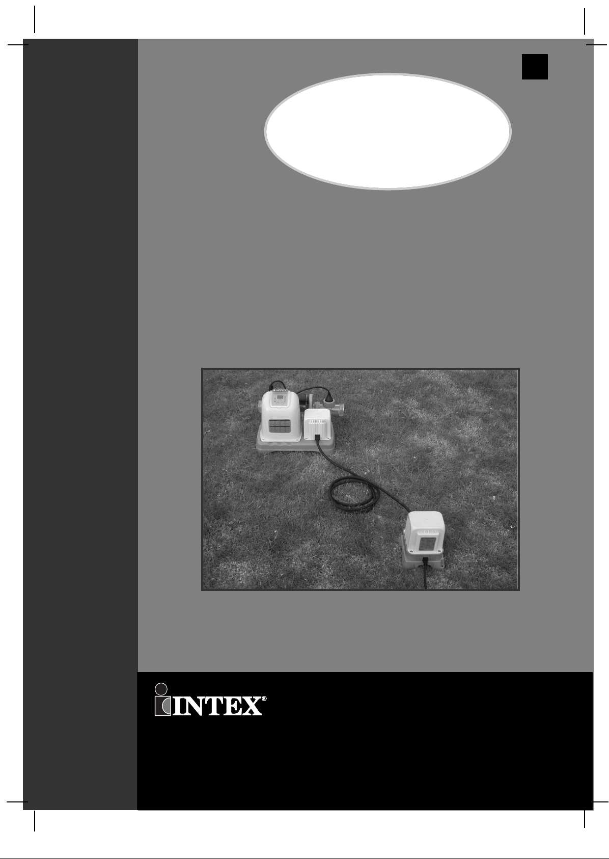
Krystal Clear™
Saltwater System
Model CS8220G, 12 V~, 50 Hz
1
GS
32
125 W, IPX5
For illustrative purposes only.
Don’t forget to try these other fine Intex products: pools, pool accessories,
inflatable pools and in-home toys, airbeds and boats available at fine
retailers or visit our website.
OOWWNNEERR’’SS MMAANNUUAALL
©2011 Intex Marketing Ltd. - Intex Development Co. Ltd. - Intex Trading Ltd.
- Intex Recreation Corp.
All rights reserved/Tous droits réservés/Todos los derechos reservados/Alle
Rechte vorbehalten. Printed in China/Imprimé en Chine/Impreso en China/Gedruckt in China.
®™ Trademarks used in some countries of the world under license from/®™ Marques utilisées dans certains pays sous
licence de/Marcas registradas utilizadas en algunos países del mundo bajo licencia de/Warenzeichen verwendet in einigen
Ländern der Welt in Lizenz von/Intex Marketing Ltd. to/à/a/an Intex Trading Ltd., Intex Development Co. Ltd., G.P.O
Box 28829, Hong Kong & Intex Recreation Corp., P.O. Box 1440, Long Beach, CA 90801 • Distributed in the European
Union by/Distribué dans l’Union Européenne par/Distribuido en la unión Europea por/Vertrieb in der Europäischen Union
durch/Intex Trading B.V., P.O. Box nr. 1075 – 4700 BB Roosendaal – The Netherlands
132-GSA-R1-1211
Page 2
(132GS) MODEL CS8220G SALTWATER SYSTEM ENGLISH 7.5” X 10.3” PANTONE 295U 11/17/2011
English
Warnings............................................................................... 3
Parts List & References....................................................... 4-6
Product Information & Specifications................................ 7
Setup Instructions................................................................ 8-12
Salt & Pool Water Volumes.................................................. 13
Intex Pools Salt Table........................................................... 14
Intex Pools Operating Time Table....................................... 15
1
GS
32
Intex Pools Cyanuric Acid Table......................................... 16
Non-Intex Pools Salt Table................................................... 17
Non-Intex Pools Operating Time Table............................... 17
Non-Intex Pools Cyanuric Acid Table................................. 17
Operating Instructions......................................................... 18-19
LED Code Chart................................................................... 20
Stationary Mounting Option................................................ 21
Maintenance.......................................................................... 22-24
Long Term Storage............................................................... 24
Pool Maintenance and Chemical Definitions..................... 25
Troubleshooting Guide........................................................ 26-27
TTAABBLLEE OOFF CCOONNTTEENNTTSS
General Aquatic Safety........................................................ 28
Limited Warranty.................................................................. 29
Intex Service Center Locations........................................... 30
SAVE THESE INSTRUCTIONS
Page 2
Page 3
(132GS) MODEL CS8220G SALTWATER SYSTEM ENGLISH 7.5” X 10.3” PANTONE 295U 11/17/2011
32
English
1
GS
Read, Understand and Follow All Instructions Carefully Before Installing and Using this Product.
READ AND FOLLOW ALL INSTRUCTIONS
WARNING
To reduce the risk of injury, do not permit children to use this product. Always
•
supervise children and those with disabilities.
• Children must stay away from this product and electrical cord(s).
• Children should be supervised to ensure that they do not play with the appliance.
• This appliance is not intended for use by persons (including children) with reduced
physical, sensory or mental capabilities, or lack of experience and knowledge. They
must at all times be supervised by a knowledgeable and experienced adult
responsible for their safety.
• Assembly and disassembly by adults only.
• Risk of electric shock. Connect transformer only to a grounding type receptacle
protected by a ground-fault circuit interrupter (GFCI) or residual current device
(RCD). Contact a qualified electrician if you cannot verify that the receptacle is
protected by a GFCI/RCD. Use a qualified electrician to install the GFCI/RCD,
which has a maximum rate of 30mA. Do not use a portable residual current device
(PRCD).
• Always unplug the transformer from the electrical outlet before removing, cleaning,
servicing or making any adjustment to the product.
• The plug must be accessible after produc t is installed.
• Do not bury the electrical cord. Locate the cord where it will not be damaged by
lawn mowers, hedge trimmers and other equipment.
• The supply cord cannot be replaced. If the cord is damaged the appliance or
transformer should be scrapped.
• To reduce the risk of electric shock, do not use extension cords, timers, plug
adaptors or converter plugs to connect unit to electric supply; provide a properly
located outlet.
• Do not attempt to plug in or unplug this product while standing in water or when
your hands are wet.
• Keep the transformer more than 3.5m away from the pool.
• Keep the plug of the transformer more than 3.5m away from the pool.
• Position this product away from the pool, so as to prevent children from climbing on
it and accessing the pool.
• Do not operate this product when the pool is occupied.
• This product is for use with storable pools only. Do not use with permanently
installed pools. A storable pool is constructed so that it may be readily
disassembled for storage and reassembled to its original configuration.
• This product is intended to be used only for the purposes described in the manual!
IMPORTANT SAFETY RULES
SSAAFFEETTYY RRUULLEESS
FAILURE TO FOLLOW THESE WARNINGS MAY RESULT IN
PROPERTY DAMAGE, ELECTRIC SHOCK, ENTANGLEMENT OR
OTHER SERIOUS INJURY OR DEATH.
These product warnings, instructions and safety rules provided with the product represent
some common risks of water recreation devices and do not cover all instances of risk and
danger. Please use common sense and good judgement when enjoying any water activity.
For portable Above-Ground-Pools only
SAVE THESE INSTRUCTIONS
Page 3
Page 4
(132GS) MODEL CS8220G SALTWATER SYSTEM ENGLISH 7.5” X 10.3” PANTONE 295U 11/17/2011
32
English
1
GS
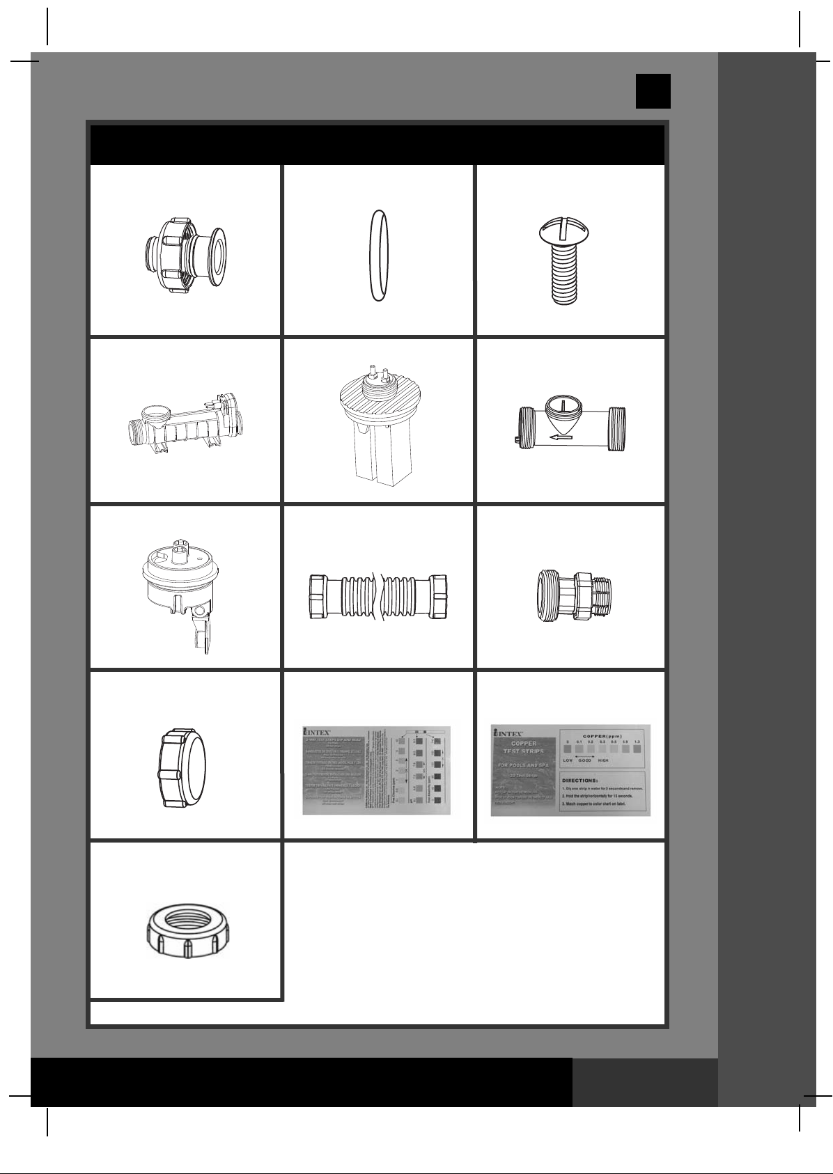
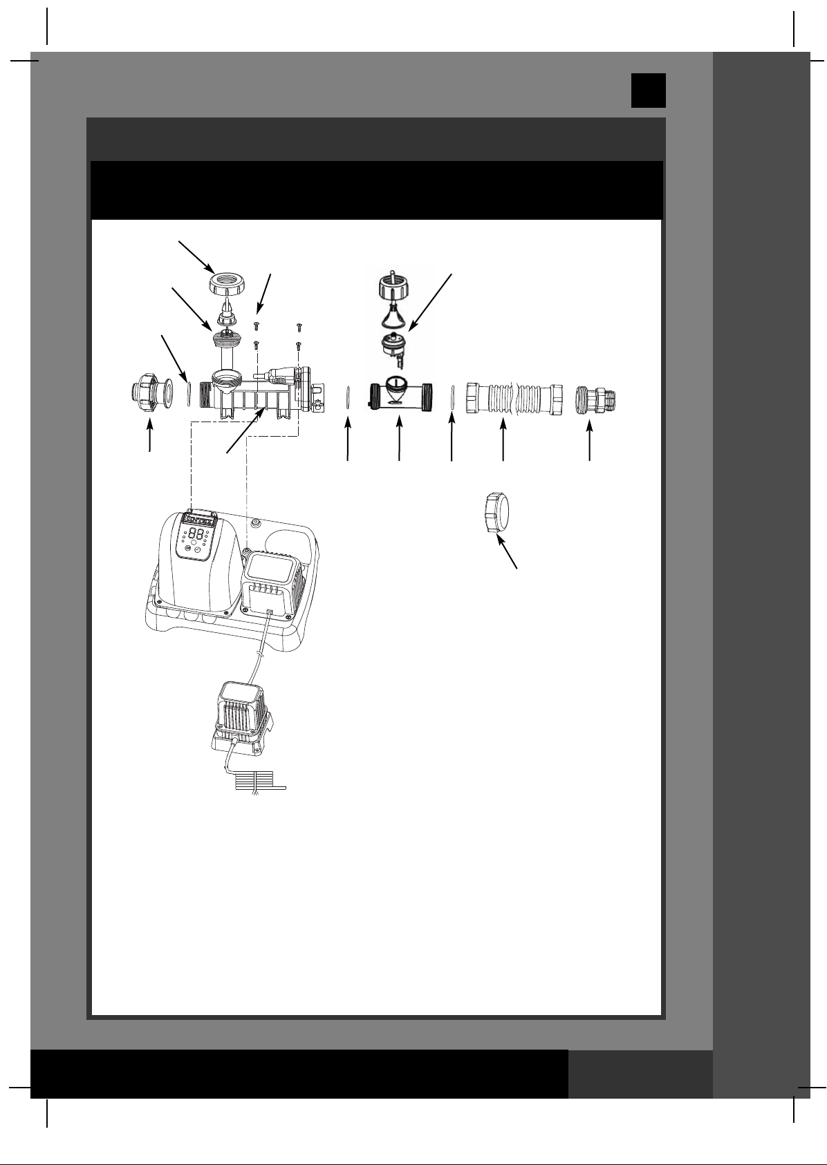
PARTS LIST
1
* Optional
4
2
5
3
6
PPAARRTTSS LLIISSTT
7
8
9
* Optional
10
13
NOTE: Drawings for illustration purpose only. Actual product may vary. Not to scale.
11 12
SAVE THESE INSTRUCTIONS
Page 4
Page 5
(132GS) MODEL CS8220G SALTWATER SYSTEM ENGLISH 7.5” X 10.3” PANTONE 295U 11/17/2011
English
PARTS REFERENCE
Before assembling your product, please take a few minutes to check the contents
nd become familiar with all the parts.
a
13
1
GS
32
5
2
1
4
3
2
6
7
2
8
10
9
PPAARRTTSS RREEFFEERREENNCCEE
NOTE: Drawings for illustration purpose only. Actual product may vary. Not to scale.
SAVE THESE INSTRUCTIONS
Page 5
Page 6
(132GS) MODEL CS8220G SALTWATER SYSTEM ENGLISH 7.5” X 10.3” PANTONE 295U 11/17/2011
English
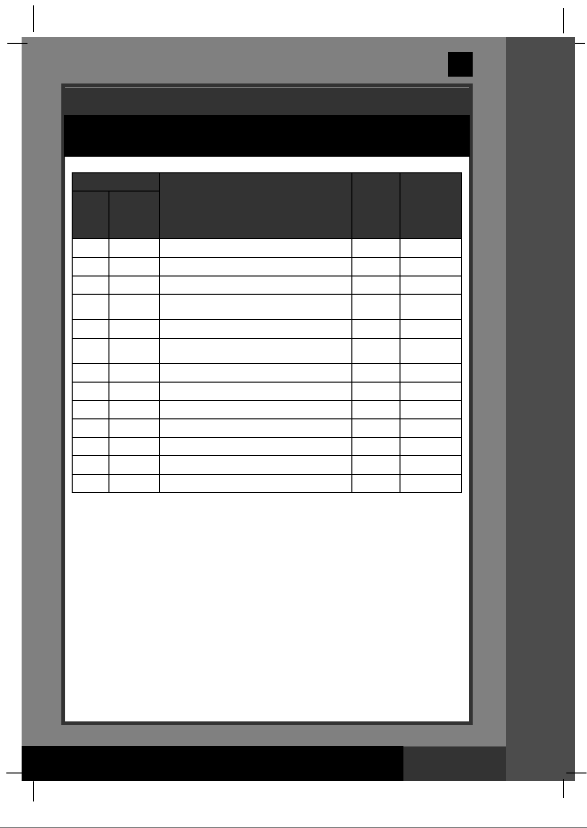
PARTS REFERENCE (continued)
Before assembling your product, please take a few minutes to check the contents
and become familiar with all the parts.
REF. NO.
PARTS FOR
COMMON
PARTS
CONNECTION
O FILTER
T
PUMPS WITH
1-1/4" (32MM)
HOSE SIZE
1
2 O-RING A 3 10712
3 SCREW 4 10713
ADAPTOR A WITH THREADED COLLAR (OPTIONAL)
DESCRIPTION QTY.
1 10849
SPARE
PART
NO.
1
GS
32
4
5 COPPER ELECTRODE 1 11234
6
7 FLOW SENSOR 1 11460
8
9 THREADED ADAPTOR B (OPTIONAL) 1 10722
10
11 CHLORINE TEST STRIPS 1 19635
12 COPPER TEST STRIPS 1 11254
13 COPPER ELECTRODE NUT 1 11488
ELECTROLYTIC CELL (WITH TITANIUM
PLATES) (O-RING A INCLUDED)
FLOW SENSOR CONDUIT (O-RING B &
O-RING C INCLUDED)
CONNECTOR HOSE WITH THREADED FITTINGS
CELL COVER
1 11233
1 11250
1 10720
2 11131
When ordering parts, be sure to quote the model number and part numbers.
PPAARRTTSS RREEFFEERREENNCCEE
SAVE THESE INSTRUCTIONS
Page 6
Page 7
(132GS) MODEL CS8220G SALTWATER SYSTEM ENGLISH 7.5” X 10.3” PANTONE 295U 11/17/2011
English
HOW THE CHLORINE IS GENERATED
This product is specially designed for above ground pools. It will destroy the
bacteria, oxidize bather organics and control algae, which provide a safe, clean and
comfortable swimming pool.
ommon salt (sodium chloride) is made up of two elements, sodium and chloride.
C
During the installation of your Saltwater System, a measured quantity of salt is
dissolved in the pool water to make it slightly salty. The pool water flows through
the Saltwater System ’s electrolytic cell to produce chlorine. The chlorine dissolves
in the water and instantly starts destroying bacteria and algae. It also oxidizes all
other organic materials.
HOW COPPER IONS ARE GENERATED
Low voltage direct current is applied to the copper electrode, and copper ions are
generated and dissolved instantly in the water. Copper is an effective algaecide,
which will prevent algae from growing in the pool.
1
GS
32
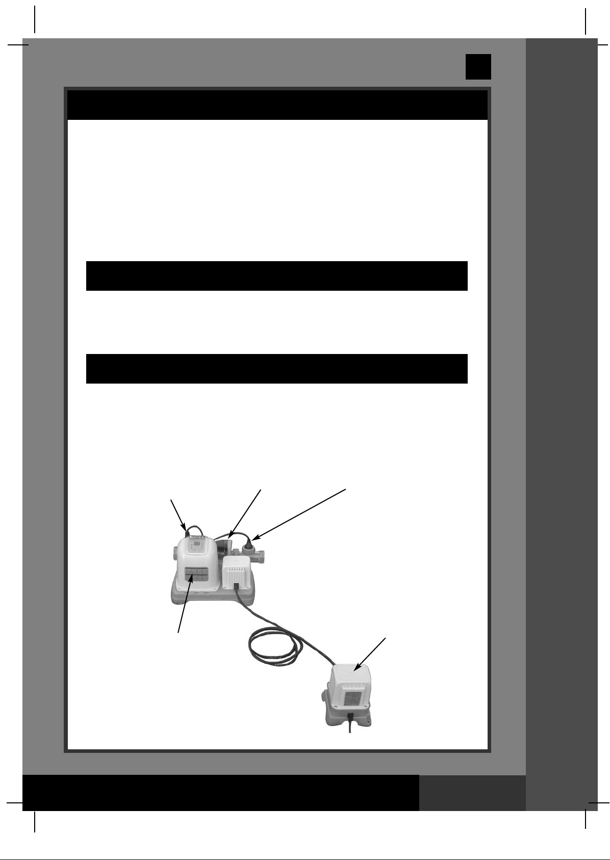
PRODUCT SPECIFICATIONS
Wattage: 125W
Ideal Salt Level: 3000 ppm (parts per million)
Maximum Chlorine Output/hour: 12 grams/hour
Copper Ionizer Output Current: 175 mA
Minimum Flow Rate:
Limited Warranty: see “Limited Warranty”
Copper electrodes
Electronic
Control Station
700 ~ 4000 gallons/hour (2650 - 15140 liters/hour)
Flow SensorElectrolytic Cell
Power Supply
SAVE THESE INSTRUCTIONS
PPRROODDUUCCTT IINNFFOORRMMAATTIIOONN//SSPPEECCSS
Page 7
Page 8
(132GS) MODEL CS8220G SALTWATER SYSTEM ENGLISH 7.5” X 10.3” PANTONE 295U 11/17/2011
BOOST
English
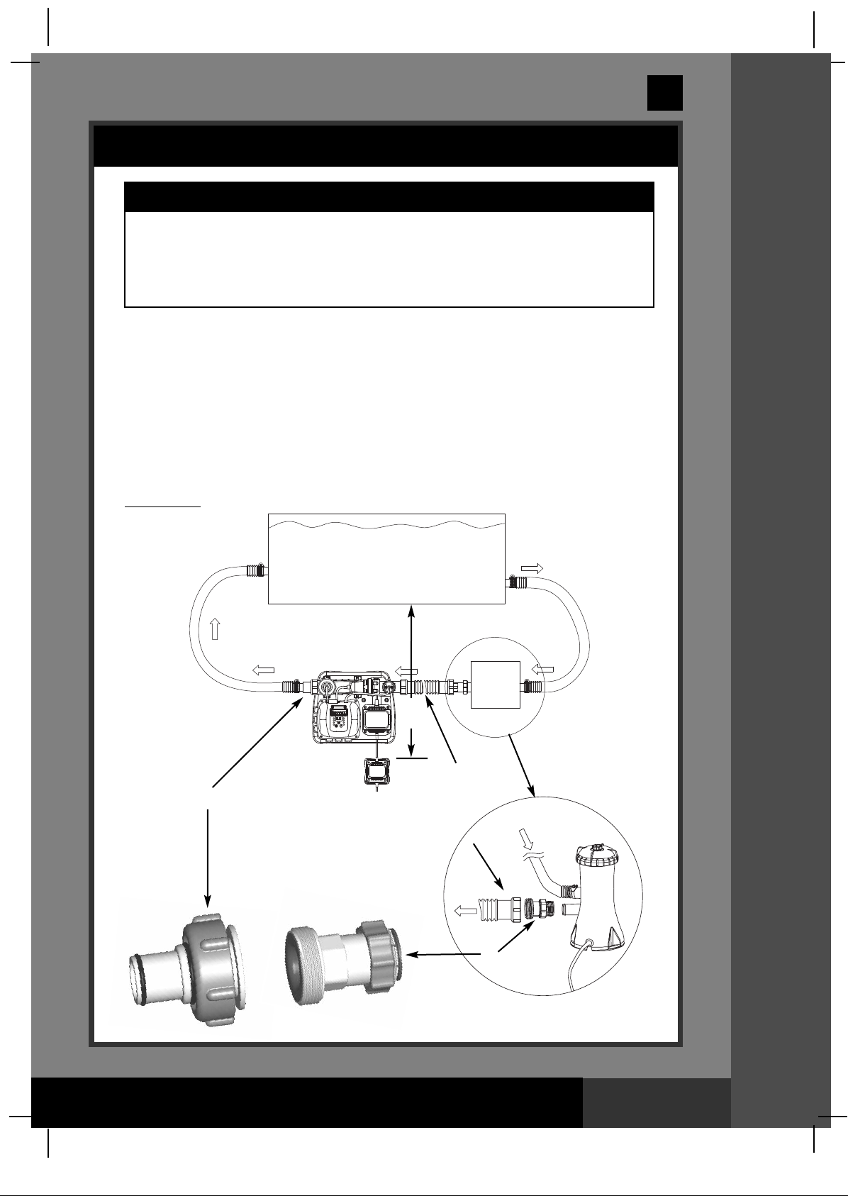
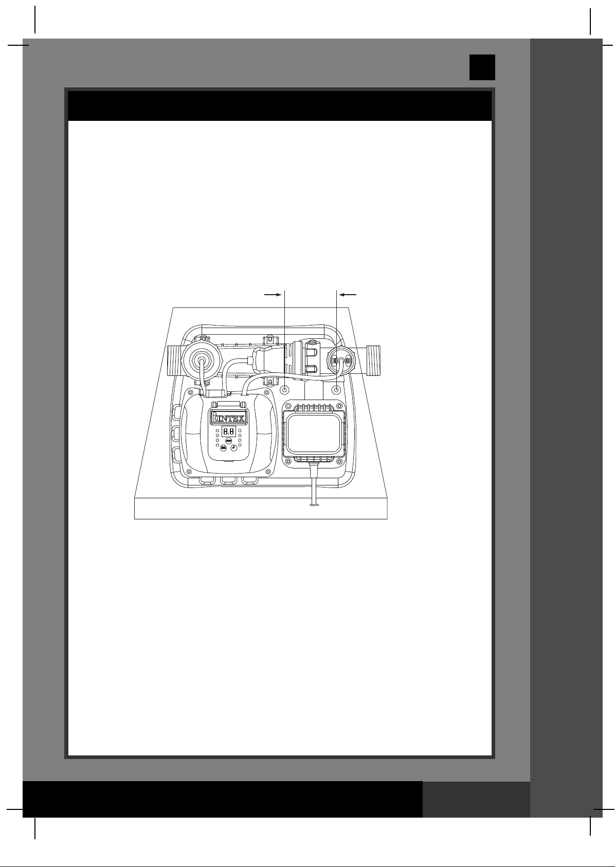
SETUP INSTRUCTION
IMPORTANT
The Saltwater System requires a separate filter pump [700~4000 gph
•
(2650~15140 lph)] to drive the water and function properly.
• The Saltwater System must be installed as the last piece of pool
equipment in the water return line to the pool as displayed in Drawing
#1. This location extends the life of the titanium plates.
1. Assemble the above-ground-pool (AGP) and its filter pump according to their
installation instructions.
2. Take the Saltwater System and its accessories out of the packaging.
3. Place the Saltwater System in line after the filter pump.
4. Connect the connector hose (8) to the Saltwater System inlet.
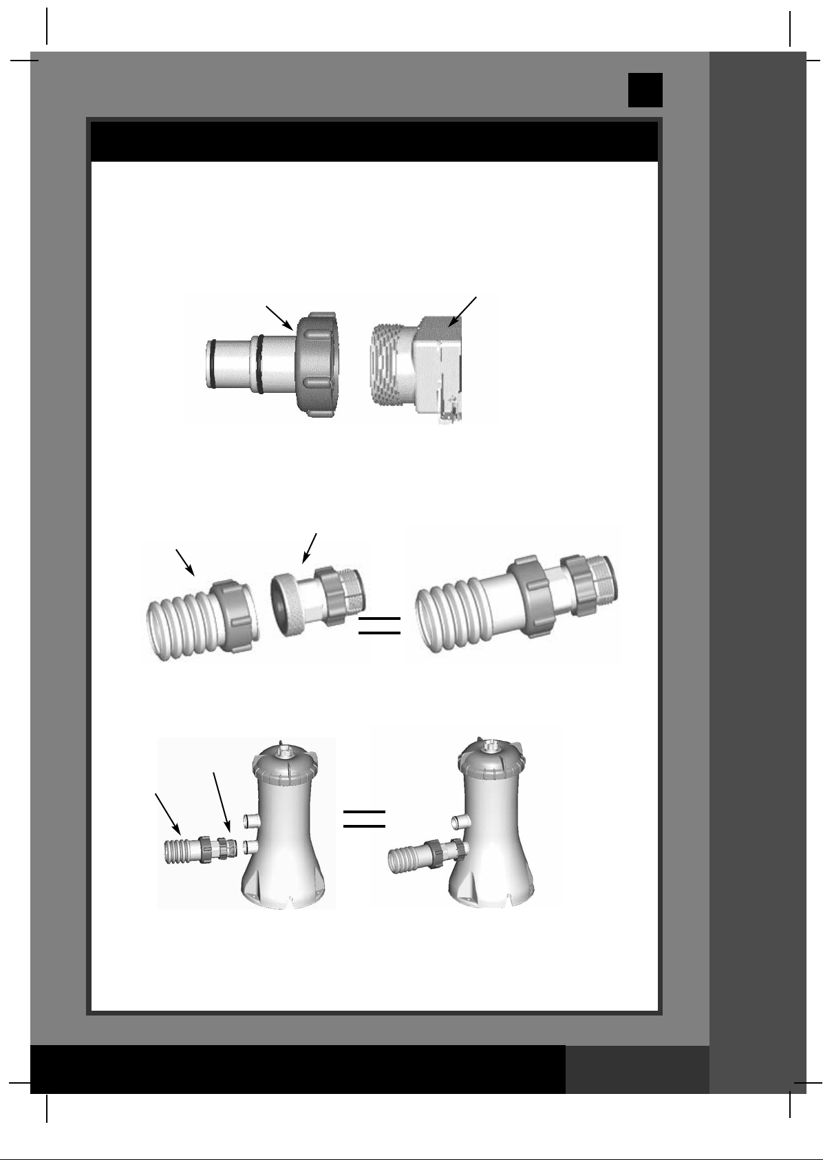
Connecting the system to pump and pool with 1-1/4” (32mm)
connections/hoses:
The saltwater system features 1-1/2” (38mm) connections. It is accordingly
supplied with adaptors A (1) and B (9) for connecting to the small 1-1/4”
(32mm) diameter connections/hoses. Install as follows:
Drawing #1
1
GS
32
WATER TO
POOL
1
SWIMMING POOL
SALTWATER
SYSTEM
WATER FROM
POOL
FILTER
PUMP
3.5M
SSEETTUUPP IINNSSTTRRUUCCTTIIOONNSS
ID 1-1/2” (38mm)
HOSE
8
SAVE THESE INSTRUCTIONS
9
Page 8
Page 9
(132GS) MODEL CS8220G SALTWATER SYSTEM ENGLISH 7.5” X 10.3” PANTONE 295U 11/17/2011
English
SETUP INSTRUCTION (continued)
1. Go directly to step 2 if your pool is empty. If your above-ground-pool is filled
with water, unscrew the strainer grids from the strainer connectors and insert
the black hat-like plugs into the connectors, before installing the saltwater pool
system.
2. Connect the adaptor A (1) to the electrolytic cell (4) outlet as shown in Drawing
#1. Tighten securely.
4
1
1
GS
32
3. Disconnect the water return hose from the filter pump connection and connect
it to the adaptor A (1) on the Saltwater System with a hose clamp. (see
Drawing #1)
4. Connect adaptor B (9) to the connector hose (8). Tighten securely. (see
Drawing #1)
9
8
5. Connect adaptor B (9) to filter pump outlet (lower connection). Tighten
securely.
9
8
SSEETTUUPP IINNSSTTRRUUCCTTIIOONNSS
6. Remove the black hat-like plugs that prevent water from flowing out of the pool.
Now, return the strainer grids to the strainer connectors.
SAVE THESE INSTRUCTIONS
Filter
Pump
Page 9
Page 10

(132GS) MODEL CS8220G SALTWATER SYSTEM ENGLISH 7.5” X 10.3” PANTONE 295U 11/17/2011
BOOST
English
SETUP INSTRUCTION (continued)
Connecting the system to pump and pool with 1-1/2” (38mm)
connections/hoses:
Pump and pool with 1-1/2” (38mm) connections do not require the adaptors
A (1) or B (9). Install as follows:
Drawing #2
PLUNGER
VALVE
ATER TO
W
POOL
WIMMING POOL
S
WATER FROM
POOL
1
GS
32
SALTWATER
SYSTEM
FILTER
PUMP
3.5M
ID 1-1/2” (38mm)
HOSE
1. Go directly to step 2 if your pool is empty. If your above-ground-pool is filled
with water, close the plunger valves before installing the Saltwater System.
2. Disconnect the water return hose from the filter pump connection and connect
it to the Saltwater System outlet.
3. Connect the connector hose (8) to the filter pump outlet connection.
4. Open the plunger valves to allow the water to flow.
SSEETTUUPP IINNSSTTRRUUCCTTIIOONNSS
SAVE THESE INSTRUCTIONS
Page 10
Page 11

(132GS) MODEL CS8220G SALTWATER SYSTEM ENGLISH 7.5” X 10.3” PANTONE 295U 11/17/2011
English
SETUP INSTRUCTION (continued)
Connecting the system to other types of pump (with different type of
thread or no thread):
The Saltwater System can also be adapted to other filter pumps with different
thread or those without a thread on the connection.
Connection to 1-1/4” (32mm) hose:
1
GS
32
8
SALTWATER SYSTEM
1. Connect one end of adaptor B (9) to the connector hose (8). Tighten securely.
2. Now, connect the other end of adaptor B (9) to the filter pump outlet. Tighten
securely.
Connection to 1-1/2” (38mm) hose with clamp:
8
SALTWATER SYSTEM
9
FILTER PUMP
ID 1-1/4” (32mm)
CONNECTION
LARGE HOSE
CLAMP
FILTER PUMP
ID 1-1/2” (38mm)
CONNECTION
1. Connect the connector hose (8) to the filter pump outlet connection with a large
hose clamp. Tighten securely.
SAVE THESE INSTRUCTIONS
SSEETTUUPP IINNSSTTRRUUCCTTIIOONNSS
Page 11
Page 12

(132GS) MODEL CS8220G SALTWATER SYSTEM ENGLISH 7.5” X 10.3” PANTONE 295U 11/17/2011
English
SETUP INSTRUCTION (continued)
Connecting the system to other types of pool
After you have connected the Saltwater System to the pump, connect it to
the pool. This is depicted in Drawings #1 and #2.
Following are the common connection types:
Connection to 1-1/4” (32mm) connectors:
OSE CLAMP
H
SALTWATER SYSTEM
1
GS
32
ID 1-1/4” (32mm)
HOSE
1. Connect the adaptor A (1) to the electrolytic cell (4) outlet. Tighten securely.
2. The adapter A (1) is now fitted to the Saltwater System. The following step is to
connect the water return hose to the adaptor A (1) with a hose clamp.
Connection to 1-1/2” (38mm) connectors without thread:
LARGE HOSE CLAMP
ID 1-1/2” (38mm)
HOSE
1
SALTWATER SYSTEM
1
SSEETTUUPP IINNSSTTRRUUCCTTIIOONNSS
1. Connect the adaptor A (1) to the electrolytic cell (4) outlet. Tighten securely.
2. With the adaptor A (1) fixed to the Saltwater System, connect the water return
hose to the adaptor, using a large hose clamp.
SAVE THESE INSTRUCTIONS
Page 12
Page 13

(132GS) MODEL CS8220G SALTWATER SYSTEM ENGLISH 7.5” X 10.3” PANTONE 295U 11/17/2011
English
SALT & POOL WATER VOLUMES
• Which kind of salt to use:
Use only Sodium Chloride Salts
Use only sodium chloride (NaCl) salt that is at least 99.8% pure. It is also
acceptable to use water conditioning salt pellets (the compressed forms of
vaporated salt). However, it will take a longer time for them to dissolve.
e
Do not use iodized or yellow (yellow prussiate of soda) colored salt.
Salt is added to the pool water and the electrolytic cell uses the salt to create
chlorine. The purer the salt the better the performance of the electrolytic cell.
• Optimum Salt Levels
The ideal salt level in the pool water is between 2500-3500 ppm (parts per million).
The optimal level is 3000 ppm.
A too low salt level will reduce the efficiency of the Saltwater System and result in
low chlorine production. A high salt level may generate a salty taste to the pool
water (this may occur at a salt level above 3500-4000ppm). Too high a salt level
may damage the power supply and cause corrosion to the pool metal fixtures and
accessories. The Salt Table page of this manual, shows the correct dosage of salt
needed. The salt in the pool is constantly recycled. The loss of salt is due only to
pool water being physically removed from the pool. Salt is not lost due to evaporation.
1
GS
32
• Adding Salt
1. Switch the filter pump on to start the water circulation.
2. Keep the Saltwater System turned off.
3. Determine the amount of salt to be added (see “Salt Table”).
4. Evenly spread the proper amount of salt around the inside perimeter of the
pool.
5. Avoid clogging the filter. Do not add salt through the skimmer.
6. Brush the pool bottom to speed up the dissolving process. Do not allow salt to
pile up on the bottom of the pool. Run the filter pump 24 consecutive hours to
thoroughly dissolve the salt.
7. After 24 hours and if all the salt is dissolved, turn on the Saltwater System,
press button until you hear a “beep”, code “00” flashing and set the saltwater
pool system to desired operating time (see “Operating Time Table”).
• Removing Salt
If too much salt has been added, the unit will beep and display “Code 92” (see
“Alarm Codes”). You will need to lower the salt concentration. The only way to do so,
is to partially drain the pool and refill it with fresh water. Drain and refill
approximately 20% of the pool’s water until the “Code 92” disappears.
• Pool Volume Calculation
Types of Pool
Rectangular
Circular
Oval
Gallons
(pool size in feet)
Length x Width x Average Depth x 7.5 Length x Width x Average Depth
Length x Width x Average Depth x 5.9 Length x Width x Average Depth x 0.79
Length x Width x Average Depth x 6.0 Length x Width x Average Depth x 0.80
Cubic Meters
(pool size in meters)
SAVE THESE INSTRUCTIONS
SSAALLTT && PPOOOOLL WWAATTEERR VVOOLLUUMMEESS
Page 13
Page 14

(132GS) MODEL CS8220G SALTWATER SYSTEM ENGLISH 7.5” X 10.3” PANTONE 295U 11/17/2011
English
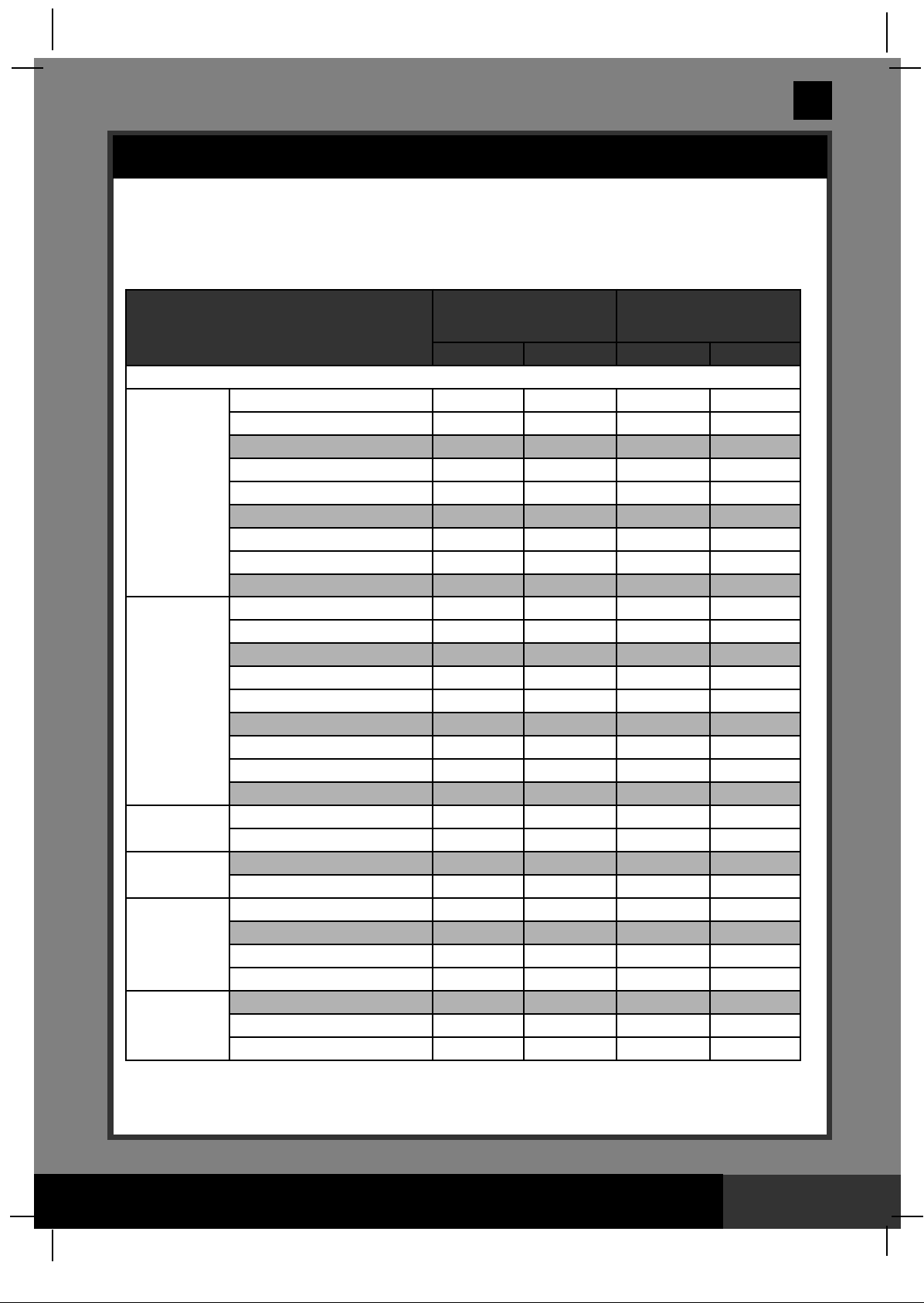
INTEX POOLS SALT TABLE
This table shows the amount of salt needed to achieve and maintain the optimal 3000 ppm
salt level.
Pool Size
INTEX ABOVE GROUND POOLS (AGP’s)
15' x 33" (457cm x 84cm)
15' x 36" (457cm x 91cm)
15' x 42" (457cm x 107cm)
EASY SET
POOL
CIRCULAR
METAL
FRAME POOL
ULTRA FRAME
POOL
SEQUOIA SPIRIT
POOL SET
OVAL FRAME
POOL
RECT. ULTRA
FRAME POOL
®
®
®
15' x 48" (457cm x 122cm)
16' x 42" (488cm x 107cm)
16' x 48" (488cm x 122cm)
18' x 42" (549cm x 107cm)
18' x 48" (549cm x 122cm)
18' x 52" (549cm x 132cm)
15' x 36" (457cm x 91cm)
15' x 42" (457cm x 107cm)
15' x 48" (457cm x 122cm)
16' x 48" (488cm x 122cm)
18' x 48" (549cm x 122cm)
18' x 52" (549cm x 132cm)
20' x 52" (610cm x 132cm)
24' x 48" (732cm x 122cm)
24' x 52" (732cm x 132cm)
16' x 48" (488cm x 122cm)
18' x 52" (549cm x 132cm)
16'8" x 49" (508cm x 124cm)
569
18'8" x 53" (
18' x 10' x 42" (549cm x 305cm x 107cm)
20' x 12' x 48" (610cm x 366cm x 122cm)
24' x 12' x 48" (732cm x 366cm x 122cm)
28' x 12' x 48" (853cm x 366cm x 122cm)
18' x 9' x 52" (549cm x 274cm x 132cm)
24' x 12' x 52" (732cm x 366cm x 132cm)
32' x 16' x 52" (975cm x 488cm x 132cm)
cm x 135cm)
Water Capacity (Calculated at
90% for Frame Pool and 80%
for Easy Set & Oval Pool)
(Gals)
2587 9792 65 30 20 10
2822 10681 65 30 20 10
3284 12430 80 35 20 10
3736 14141 95 45 20 10
3754 14209 95 45 20 10
4273 16173 110 50 30 15
4786 18115 120 55 30 15
5455 20647 135 60 35 15
5894 22309 150 65 40 20
3282 12422 80 35 20 10
3861 14614 100 45 20 10
4440 16805 110 50 30 15
5061 19156 125 55 30 15
6423 24311 160 75 40 20
6981 26423 175 80 45 20
8638 32695 220 100 60 25
11483 43462 290 130 75 35
12481 47241 310 140 85 40
5061 19156 125 55 35 15
6981 26423 175 80 45 20
5061 19156 125 55 35 15
6981 26423 175 80 45 20
2885 10920 65 30 20 10
4393 16628 110 50 30 15
5407 20465 135 60 35 15
6420 24300 160 75 40 20
4545 17203 115 50 30 15
8403 31805 210 100 55 25
14364 54368 360 165 95 45
Liters)
(
Salt Needed for
Startup
3.0g/L (3000ppm)
Lbs)(Kgs)(Lbs)(Kgs)
(
Salt Needed when
Low Salt Detected
(CODE “91”)
132
GS
SAVE THESE INSTRUCTIONS
Page 14
Page 15

(132GS) MODEL CS8220G SALTWATER SYSTEM ENGLISH 7.5” X 10.3” PANTONE 295U 11/17/2011
INTEX POOLS OPERATING TIME TABLE (WITH CYANURIC ACID)
Operating Time (hours)
at different ambient/air
temperatures
10 - 19°C
(50 - 66°F)
1
1
1
1
1
2
2
2
2
1
1
2
2
2
2
3
4
5
2
2
2
2
1
2
2
2
2
3
6
20 - 28 °C
(68 - 82 °F)
1
1
1
2
2
2
2
2
2
1
2
2
2
2
2
3
4
5
2
2
2
2
1
2
2
2
2
3
6
29 - 36 °C
(84 - 97 °F)
Pool Size
INTEX ABOVE GROUND POOLS (AGP’s)
15' x 33" (457cm x 84cm)
15' x 36" (457cm x 91cm)
15' x 42" (457cm x 107cm)
EASY SET
POOL
CIRCULAR
METAL
FRAME POOL
ULTRA FRAME
POOL
SEQUOIA SPIRIT
POOL SET
OVAL FRAME
POOL
RECT. ULTRA
FRAME POOL
®
15' x 48" (457cm x 122cm)
16' x 42" (488cm x 107cm)
16' x 48" (488cm x 122cm)
18' x 42" (549cm x 107cm)
18' x 48" (549cm x 122cm)
18' x 52" (549cm x 132cm)
15' x 36" (457cm x 91cm)
15' x 42" (457cm x 107cm)
15' x 48" (457cm x 122cm)
16' x 48" (488cm x 122cm)
18' x 48" (549cm x 122cm)
18' x 52" (549cm x 132cm)
20' x 52" (610cm x 132cm)
24' x 48" (732cm x 122cm)
24' x 52" (732cm x 132cm)
®
16' x 48" (488cm x 122cm)
18' x 52" (549cm x 132cm)
®
16'8" x 49" (508cm x 124cm)
569
18'8" x 53" (
18' x 10' x 42" (549cm x 305cm x 107cm)
20' x 12' x 48" (610cm x 366cm x 122cm)
24' x 12' x 48" (732cm x 366cm x 122cm)
28' x 12' x 48" (853cm x 366cm x 122cm)
18' x 9' x 52" (549cm x 274cm x 132cm)
24' x 12' x 52" (732cm x 366cm x 132cm)
32' x 16' x 52" (975cm x 488cm x 132cm)
cm x 135cm)
Water Capacity (Calculated at
90% for Frame Pool and 80%
for Easy Set & Oval Pool)
(Gals) (Liters)
2587
2822
3284
3736
3754
4273
4786
5455
5894
3282
3 861
4440
5061
6423
6981
8638
11483
12481
5061
6981
5061
6981
2885
4393
5407
6420
4545
8403
14364
9792
10681
12430
14141
14209
16173
18115
20647
22309
12422
14614
16805
19156
24311
26423
32695
43462
47241
19156
26423
19156
26423
10920
16628
20465
24300
17203
31805
54368
English
Intex Filter
Operating
1
1
2
2
2
2
2
3
3
2
2
2
2
3
3
4
5
6
2
3
2
3
1
2
3
3
2
4
7
132
GS
pump
Time
(hours)
2
2
4
4
4
4
4
4
4
4
4
4
4
4
4
4
6
8
4
4
4
4
2
4
4
4
4
6
8
IMPORTANT
The filter pump running time should be 1 hour longer than the required
operating time of the Saltwater System.
SAVE THESE INSTRUCTIONS
Page 15
Page 16
(132GS) MODEL CS8220G SALTWATER SYSTEM ENGLISH 7.5” X 10.3” PANTONE 295U 11/17/2011
English
INTEX POOLS CYANURIC ACID TABLE
yanuric acid is a chemical that reduces the loss of chlorine in water due to ultraviolet
C
rays. To maintain maximum performance, we recommend that the cyanuric acid level be
maintained at approximately
cyanuric acid.
Pool Size
INTEX ABOVE GROUND POOLS (AGP’s)
15' x 33" (457cm x 84cm)
15' x 36" (457cm x 91cm)
15' x 42" (457cm x 107cm)
EASY SET
POOL
CIRCULAR
METAL
FRAME POOL
ULTRA FRAME
POOL
SEQUOIA SPIRIT
POOL SET
OVAL FRAME
POOL
RECT. ULTRA
FRAME POOL
®
®
®
15' x 48" (457cm x 122cm)
16' x 42" (488cm x 107cm)
16' x 48" (488cm x 122cm)
18' x 42" (549cm x 107cm)
18' x 48" (549cm x 122cm)
18' x 52" (549cm x 132cm)
15' x 36" (457cm x 91cm)
15' x 42" (457cm x 107cm)
15' x 48" (457cm x 122cm)
16' x 48" (488cm x 122cm)
18' x 48" (549cm x 122cm)
18' x 52" (549cm x 132cm)
20' x 52" (610cm x 132cm)
24' x 48" (732cm x 122cm)
24' x 52" (732cm x 132cm)
16' x 48" (488cm x 122cm)
18' x 52" (549cm x 132cm)
16'8" x 49" (508cm x 124cm)
18'8" x 53" (569cm x 135cm)
18' x 10' x 42" (549cm x 305cm x 107cm)
20' x 12' x 48" (610cm x 366cm x 122cm)
24' x 12' x 48" (732cm x 366cm x 122cm)
28' x 12' x 48" (853cm x 366cm x 122cm)
18' x 9' x 52" (549cm x 274cm x 132cm)
24' x 12' x 52" (732cm x 366cm x 132cm)
32' x 16' x 52" (975cm x 488cm x 132cm)
1% of the salt, i.e. 100 Lbs (45 Kgs) salt x1% = 1 Lbs (0.45 Kgs)
Water Capacity (Calculated at
90% for Frame Pool and 80%
for Easy Set & Oval Pool)
(Gals)
2587 9792 0.6 0.3
2822 10681 0.7 0.3
3284 12430 0.8 0.4
3736 14141 0.9 0.4
3754 14209 0.9 0.4
4273 16173 1.1 0.5
4786 18115 1.2 0.5
5455 20647 1.4 0.6
5894 22309 1.5 0.7
3282 12422 0.8 0.4
3861 14614 1.0 0.4
4440 16805 1.1 0.5
5061 19156 1.3 0.6
6423 24311 1.6 0.7
6981 26423 1.7 0.8
8638 32695 2.2 1.0
11483 43462 2.9 1.3
12481 47241 3.1 1.4
5061 19156 1.3 0.6
6981 26423 1.7 0.8
5061 19156 1.3 0.6
6981 26423 1.7 0.8
2885 10920 0.7 0.3
4393 16628 1.1 0.5
5407 20465 1.4 0.6
6420 24300 1.6 0.7
4545 17203 1.1 0.5
8403 31805 2.1 1.0
14364 54368 3.6 1.6
(Liters) (Lbs) (Kgs)
Cyanuric Acid Needed for
Startup
0.03g/L (30ppm)
132
GS
SAVE THESE INSTRUCTIONS
Page 16
Page 17

(132GS) MODEL CS8220G SALTWATER SYSTEM ENGLISH 7.5” X 10.3” PANTONE 295U 11/17/2011
SALT CALCULATION FORMULA FOR ALL POOLS
Salt Needed for Startup
(Lbs)
Water Capacity (Gals) x 0.025
Salt Needed for Startup
(Kgs)
Water Capacity (Liters) x 0.003
Salt Needed when
Low Salt Detected (Lbs)
Water Capacity (Gals) x 0.0067 Water Capacity (Liters) x 0.0008
Salt Needed when
Low Salt Detected (Kgs)
SALT TABLE FOR COMMON NON-INTEX POOLS
Salt Needed when
Water Capacity Salt Needed for Startup
(Gals) (Liters) (Lbs) (Kgs) (Lbs) (Kgs)
2000 7500 50 20 10 5
4000 15000 100 45 25 10
6000 22500 150 65 40 20
8000 30000 200 90 55 25
10000 37500 250 110 70 30
12000 45500 300 135 80 35
14000 53000 350 160 95 45
Low Salt Detected
(CODE “91”)
English
132
GS
OPERATING TIME TABLE FOR COMMON NON-INTEX POOLS
Water Capacity
(Gals) (Liters)
2000
4000
6000
8000
10000
12000
14000
7500
15000
22500
30000
37500
45500
53000
10 - 19°C
(50 - 66°F)
1
2
2
3
4
5
6
Operating Time (hours)
at different ambient/air temperatures
20 - 28 °C
(68 - 82 °F)
1
2
2
3
4
5
6
29 - 36 °C
(84 - 97 °F)
CYANURIC ACID TABLE FOR COMMON NON-INTEX POOLS
Water Capacity
(Gals) (Liters) (Lbs) (Kgs)
2000
4000
6000
8000
10000
12000
14000
7500
15000
22500
30000
37500
45500
53000
Cyanuric Acid Needed for Startup
0.5
1.0
1.5
2.0
2.5
3.0
3.5
0.03g/L (30ppm)
0.23
0.45
0.68
0.90
1.13
1.37
1.59
1
2
3
4
5
6
7
SAVE THESE INSTRUCTIONS
Page 17
Page 18

(132GS) MODEL CS8220G SALTWATER SYSTEM ENGLISH 7.5” X 10.3” PANTONE 295U 11/17/2011
OK
0
Copper (ppm)
0.1 0.2 0.5 0.9 1.3
English
OPERATION INSTRUCTIONS
1. Turn on the filter pump.
2. Start up the unit:
Plug the power cord into the
electrical outlet and test the
FCI/RCD (circuit breaker). Switch
G
on the unit. Flashing code “00” appears
on the electronic control station’s LED,
indicating that the unit is ready to be
programmed.
3. Set operating hours for Saltwater system:
With code “00” flashing, press button to
set the desired operating hours. See the
“Operating Time Table” for the required
operating hours related to each pool size.
Pressing will increase the time from 01
to 12 hours maximum. If you have selected
too many hours keep pressing to repeat
the cycle. The built-in timer will now activate
your Saltwater System, at the same time each
day, for the number of hours you have set.
NOTE: The Saltwater System will not operate if the filter pump is not operating.
Make sure to program your filter pump (or start it manually) for operation
beginning 5 minutes before the saltwater system and finishing 15 minutes after
the saltwater system.
(1 to 12 hours max per cycle)
1
GS
32
4. Lock keypad controls:
With the desired hour value showing, press button until
you hear a “beep”. A green “WORKING” indicator on the
control panel will light up within a few seconds to indicate that
the saltwater system has started chlorine production. Locking
the control buttons into this setting prevents unauthorized
changing of the operating cycle.
NOTE: If you forget to lock the keypad controls, the system
will automatically lock it and start working 1 minute later.
5. Readjust operating time if necessary:
The operating hours can be re-adjusted if necessary.
Press button until you hear a “beep” to unlock the
keypad and the current programmed time will flash.
Repeat steps 3 to 4.
6. Test the copper concentration in the
pool water.
The Saltwater System recommends a copper level of 0.1 to 0.2 ppm. This is
easily tested by the copper ion test strips provided. If the test result is 0.1~0.2
ppm, go directly to step 8.
OOPPEERRAATTIINNGG IINNSSTTRRUUCCTTIIOONNSS
SAVE THESE INSTRUCTIONS
Page 18
Page 19
(132GS) MODEL CS8220G SALTWATER SYSTEM ENGLISH 7.5” X 10.3” PANTONE 295U 11/17/2011
English
OPERATION INSTRUCTIONS (continued)
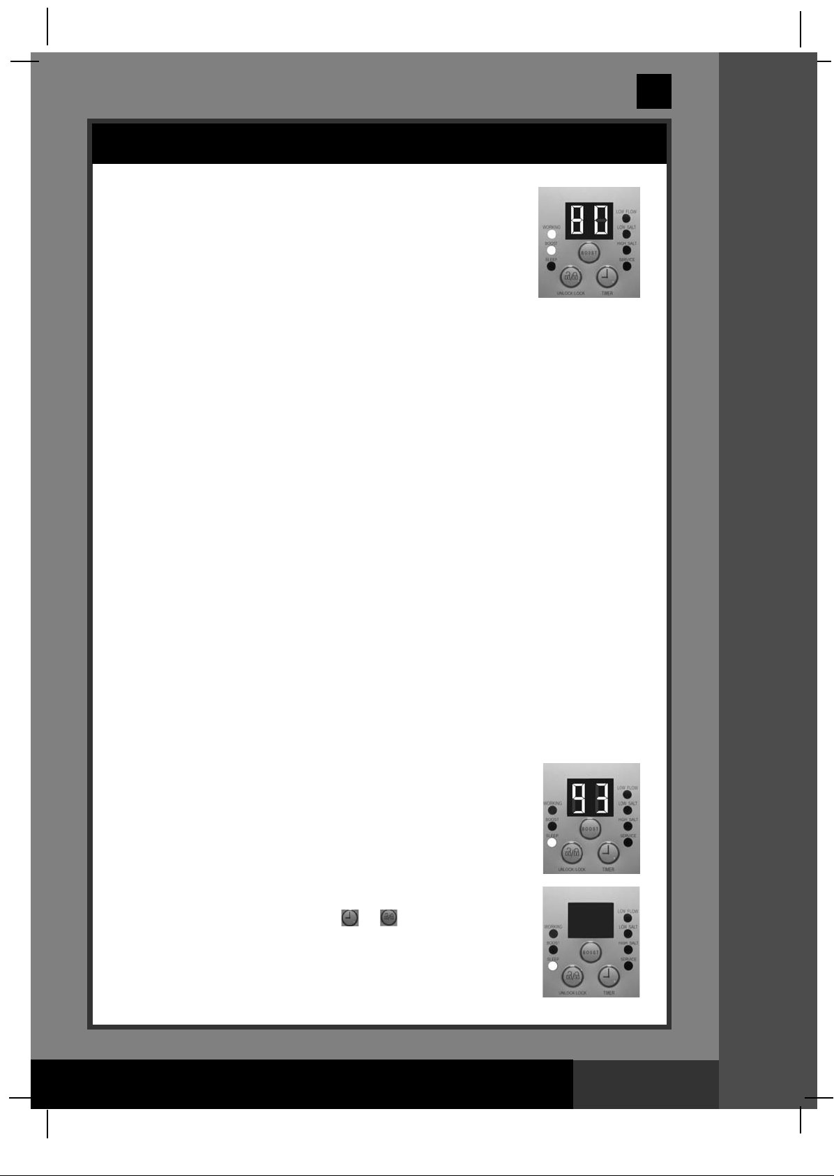
7. Boost cycle
• If the test result is below 0.1ppm, press and hold “BOOST”
button for 5 seconds until the indicator lights up and the
ED display shows “80”. This indicates that the saltwater
L
system has started copper ion and more chlorine sanitizer
production. You can press and hold the “BOOST” button for
another 5 seconds until the indicator is off, which will cancel
the Boost cycle.
Note: Once the system has started copper ion and more chlorine sanitizer
production, the boost button can’t be re-set until the power switch is off.
• The boost operating hours is 4 times the amount of time programmed into the
system, i.e. if your saltwater system operating time is 2 hours, the boost procedure
will run 4 x 2 = 8 hours. After boost procedure has been completed, the system
will automatically switch to the normal working mode.
1
GS
32
• Once the boost is operating, check whether the filter pump operating hours
have been set properly. For example, the boost operating time is 8 hours, the
filter pump should be set to run for 8 hours at least. Increase the filter pump
operating time if necessary.
Note: If an Intex filter pump is attached to the system, set the pump switch to
on “I” position.
• After a heavy rain or if the pool is dirty, press the “BOOST” button to shock the
pool again.
8. Test pool water regularly:
Once the copper level appears to be balanced, test the pool water every week
to maintain the proper sanitizer level.
It’s very important that the free chlorine is between 0.4-1.5 ppm and copper
ion concentration is between 0.1~0.2 ppm. When the copper level is below 0.1
ppm, repeat step 7.
NOTE: A High copper ion concentration may cause blonde hair to exhibit a
green hair. To prevent this, wear a swimming cap during swimming, and wash
hair with special shampoo after using the pool.
See “Troubleshooting Guide”.
9. Stand-by/power saving mode:
• When the cycle ends, the green “SLEEP” indicator on the
control panel lights up and the LED display flashes “93”.
The system is now in Stand-By mode. After a while, it
shuts down and sets itself in a Power Saving mode. The
system will automatically turn itself back on in 24 hours,
starting its daily cycle of chlorine production.
• The “SLEEP” indicator stays on, while the system is in the
Power Saving mode. The LED display however, goes blank
after 1 hour. Press any button ( or ) to view the last LED
code.
SAVE THESE INSTRUCTIONS
OOPPEERRAATTIINNGG IINNSSTTRRUUCCTTIIOONNSS
Page 19
Page 20
(132GS) MODEL CS8220G SALTWATER SYSTEM ENGLISH 7.5” X 10.3” PANTONE 295U 11/17/2011
32
English
1
GS
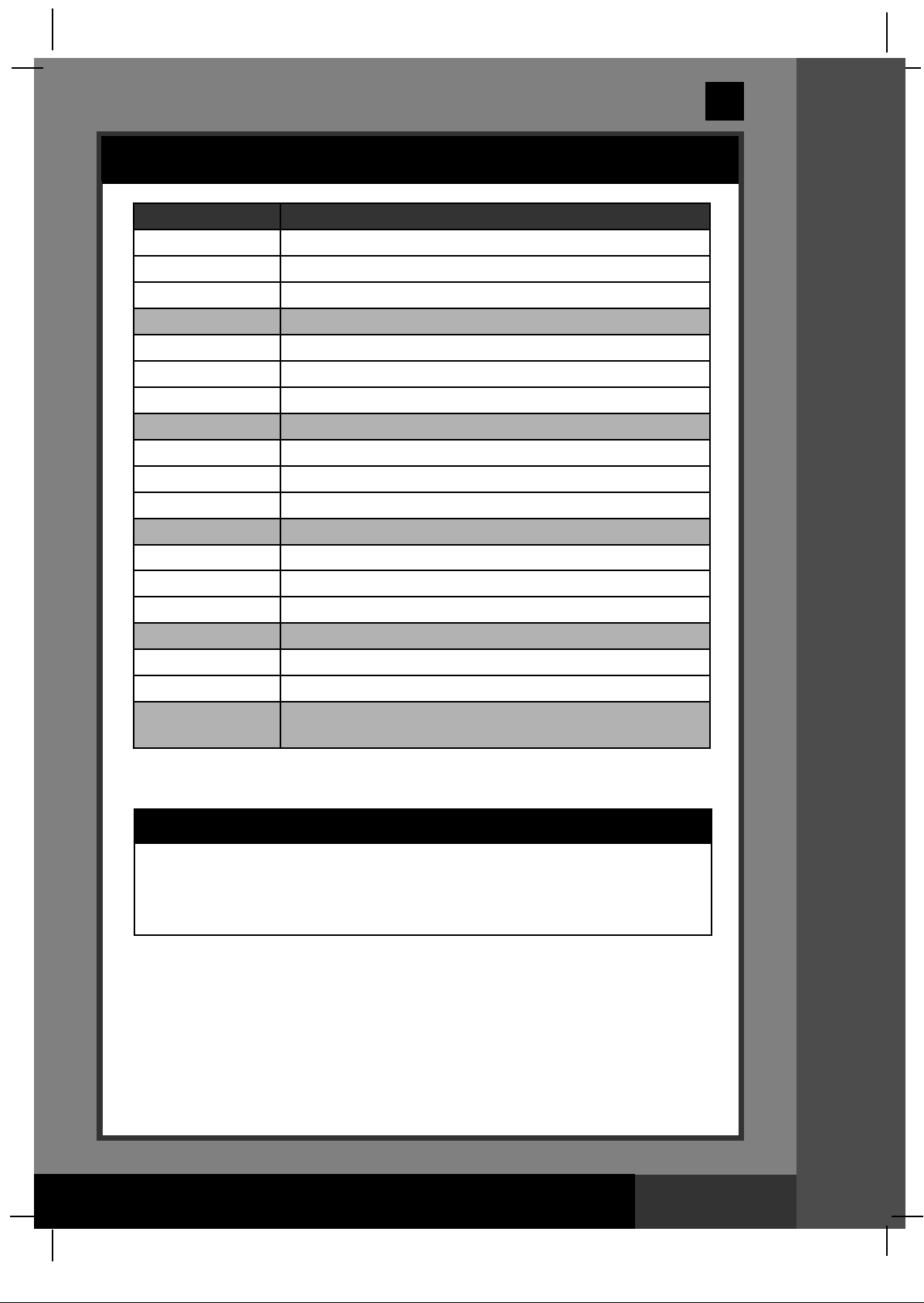
LED CODE CHART
ED Reading
L
80 Boost Mode
00 Stand-By Mode (Start-up)
1 Minimum Operating Hour (1 hour remaining)
0
02 Operating Hours (2 hours remaining)
03 Operating Hours (3 hours remaining)
04 Operating Hours (4 hours remaining)
05 Operating Hours (5 hours remaining)
06 Operating Hours (6 hours remaining)
07 Operating Hours (7 hours remaining)
08 Operating Hours (8 hours remaining)
09 Operating Hours (9 hours remaining)
10 Operating Hours (10 hours remaining)
11 Operating Hours (11 hours remaining)
12 Maximum Operating Hours (12 hours remaining)
90 Alarm Code (Low Water Flow / No Flow)
91 Alarm Code (Low Salt Level)
92 Alarm Code (High Salt Level)
93 Stand-By Mode (Operating Process finished)
“BLANK” No Power or “Power Saving Mode” waiting to start next
Saltwater System cycle.
efinitions
D
LLEEDD CCOODDEE CCHHAARRTT
IMPORTANT
When Code “90” alarm is shown, ensure the timer of the filter pump is set
one (1) hour longer than the Saltwater System.
If the filter pump does not have a built-in timer, the filter pump needs to
be turned on/off manually every day.
SAVE THESE INSTRUCTIONS
Page 20
Page 21
(132GS) MODEL CS8220G SALTWATER SYSTEM ENGLISH 7.5” X 10.3” PANTONE 295U 11/17/2011
English
SALTWATER SYSTEM STATIONARY MOUNTING OPTION
Some countries, especially in the European community, require the product
to be secured to the ground or to a base in a permanent upright position.
Check with your local authorities to determine if there is a regulation in your
area regarding above-the-ground swimming pool filter pumps. If yes, then
the product can be mounted to a platform using the two holes located in the
base. See drawing below.
The product can be mounted on a cement base or onto a wooden platform
to prevent accidental tipping. Total assembly must exceed 18kg .
97 mm
1
GS
32
1. The mounting holes are 6.4 mm in diameter and spaced 97 mm apart.
2. Use two bolts and lock nuts with a maximum of 6.4 mm in diameter.
SAVE THESE INSTRUCTIONS
SSTTAATTIIOONNAARRYY MMOOUUNNTTIINNGG OOPPTTIIOONN
Page 21
Page 22
(132GS) MODEL CS8220G SALTWATER SYSTEM ENGLISH 7.5” X 10.3” PANTONE 295U 11/17/2011
English
MAINTENANCE
IMPORTANT
Unplug the power cord before cleaning your system. Also close the plunger
valves on your pool or insert the black hat-like plugs in the strainer opening
to prevent water spillage. After completing all maintenance tasks, you must
plug the power cord back in and open the plunger valves or remove the
plugs.
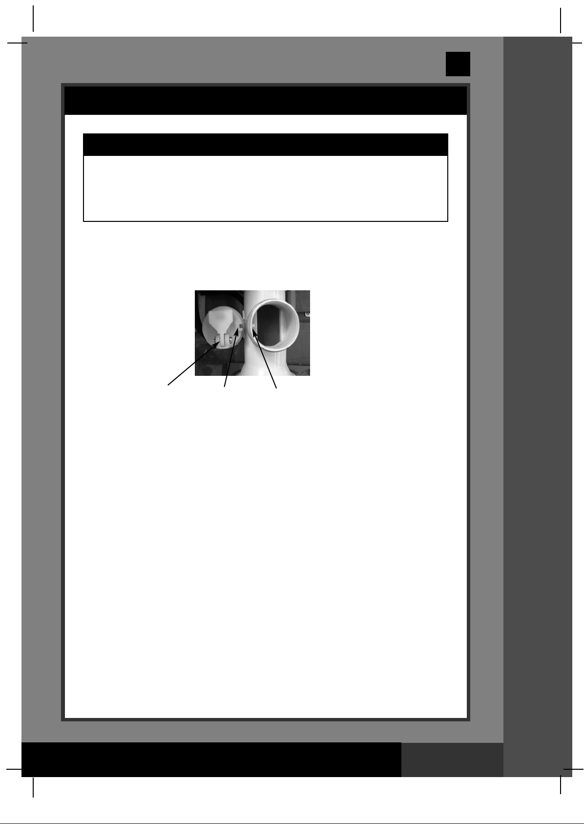
Flow Sensor Cleaning
1. In a counter-clockwise motion unscrew the collar of the flow sensor (7) and
remove it from the electrolytic cell conduit (6). See “Part Reference”.
2. If deposits and debris are seen on the surface of the flow sensor, then use a
garden hose to wash it off.
1
GS
32
Hinge
3. If flushing with water does not remove the deposits, use a plastic brush to
clean the surface and the hinge if necessary. Do not use a metal brush.
4. After the flow sensor has been inspected and cleaned, align the locator notch
on the flow sensor to the connection ridge in the conduit. Now turn the collar in
a clockwise motion, tightening the sensor back into its position. Do not
overtighten.
Electrolytic Cell Cleaning
The electrolytic cell (4) has a self cleaning function incorporated into the electronic
control's programming. In most cases this self cleaning action will keep the cell
working at optimum efficiency. If the pool water is hard (high mineral content) the
cell may require periodic manual cleaning. To maintain maximum performance, we
recommend that you open and visually inspect the electrolytic cell (4) monthly.
The following steps provide instructions on how to clean your cell.
Inspection and cleaning:
1. Switch off the unit, unplug the power cord from the electrical socket.
2. For filter pumps with 1-1/4” (32mm) hose size - To prevent water from
flowing out of the pool, unscrew the strainer grids from the strainer connectors
and insert the hat-like plugs into the strainer connectors.
For filter pumps with 1-1/2” (38mm) hose size - Grasp a plunger valve
handle. Turn the handle counter-clockwise, push down until it stops and then
turn it clockwise until the plastic protruding notch anchors in the "0/I" position.
Repeat for the second plunger valve. This prevents the water from flowing out
of the pool.
Locator Notch
Connection Ridge
MMAAIINNTTEENNAANNCCEE
SAVE THESE INSTRUCTIONS
Page 22
Page 23
(132GS) MODEL CS8220G SALTWATER SYSTEM ENGLISH 7.5” X 10.3” PANTONE 295U 11/17/2011
English
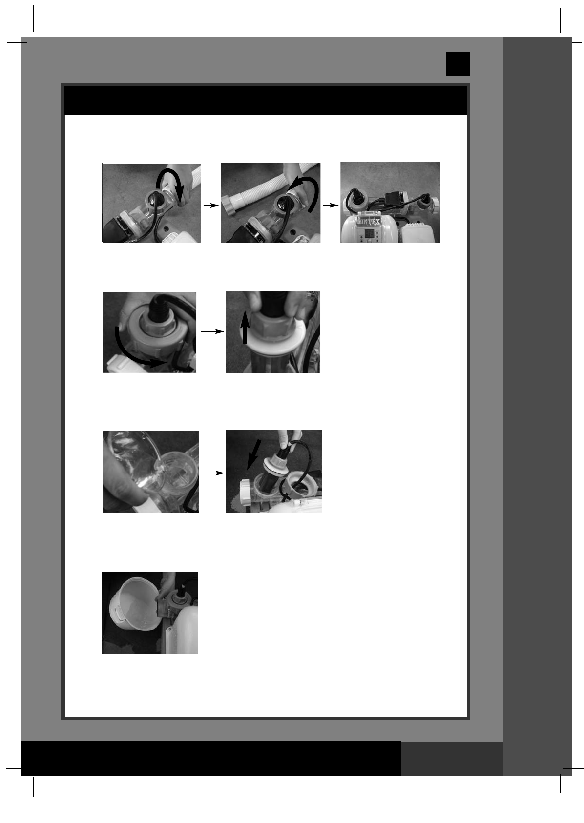
MAINTENANCE (continued)
3. Disconnect the 2 hoses from the Saltwater System, and assemble the cell
cover (10) at each side of the cell.
4. In a counter-clockwise motion, unscrew the collar of the copper electrode (5)
and remove it from the electrolytic cell (4). Lift up the copper electrode.
1
GS
32
5. Pour kitchen grade vinegar into the cell to immerse the titanium plates. Then
put the copper electrode back in the cell, soak them for about one hour until
no colored areas remain.
6. Open one side of the cell cover (10), drain and properly dispose of the vinegar.
Connect the hose which goes from the pool to the cell. Flush the cell with the
pool water.
MMAAIINNTTEENNAANNCCEE
7. Reverse steps 3, 4, 5 and 6 to reconnect the electrolytic cell.
SAVE THESE INSTRUCTIONS
Page 23
Page 24
(132GS) MODEL CS8220G SALTWATER SYSTEM ENGLISH 7.5” X 10.3” PANTONE 295U 11/17/2011
English
MAINTENANCE (continued)
INTEX®COPPER ION TEST STRIPS (PACKED WITH THE PRODUCT)
The Copper Ion Test Strips can be used to test the copper ion concentration in the
water.
Directions and Use
1. Dip the entire strip into the water for 3 seconds, then remove it.
2. Hold the strip level for 15 seconds. Do not shake excess water from the strip.
3. Now compare the copper ion strip pad to the color chart on the packaging
label.
1
GS
32
INTEX®3-WAY TEST STRIPS (PACKED WITH THE PRODUCT)
The 3-Way Test Strips can test the “Free Chlorine”, “pH”, and “Total Alkalinity” levels
at the same time. We recommend that you test the water chemistry weekly, and
maintain the chlorine concentration at 0.4-1.5 ppm.
Directions and Use
1. Dip the entire strip into the water and remove immediately.
2. Hold the strip level for 15 seconds. Do not shake excess water from the strip.
3. Now compare the strip pad to the color chart on the packaging label. If
necessary, adjust the chemical level in the pool water. It is very important, to
use the proper technique when testing the water's chemical level. Read and
follow the written strip instructions carefully.
LONG TERM STORAGE
1. Disconnect the power cord from the electrical outlet.
2. After the pool is completely empty, disconnect the Saltwater System from the
hoses by reversing the installation instructions.
3. Air-dry the unit before you store it. This might be a good time to visually inspect
and clean the electrolytic cell.
4. Store the unit and accessories in a dry place. The temperature should be
controlled, between 32 degrees Fahrenheit (0 degrees Celsius) and 97
degrees Fahrenheit (36 degrees Celsius).
5. The original package can be used for storage.
MMAAIINNTTEENNAANNCCEE
SAVE THESE INSTRUCTIONS
Page 24
Page 25
(132GS) MODEL CS8220G SALTWATER SYSTEM ENGLISH 7.5” X 10.3” PANTONE 295U 11/17/2011
English
POOL MAINTENANCE & CHEMICAL DEFINITIONS
Preferred Water Chemistry Reading
Minimum Ideal Maximum
opper Ions 0 0.1 - 0.2 ppm 0.2 ppm
C
Free Chlorine 0 0.4 - 1.5 ppm 3.0 ppm
Combined Chlorine 0 0 ppm 0.2 ppm
pH 7.2 7.4 - 7.6 7.8
Total Alkalinity 100 ppm 100 - 140 ppm 140 ppm
Calcium Hardness 150 ppm 200 - 400 ppm 500 - 1000 ppm
Stabilizer (Cyanuric Acid) 10 ppm 30 - 50 ppm 100 ppm
Consult with local swimming pool dealer for water treatment.
Free Chlorine - Is the chlorine residual present in pool water.
Combined Chlorine - Is formed by the reaction of free chlorine with ammonia
wastes.
Result if too high - Sharp chlorinous odor, eye irritation.
1
GS
32
pH
- A value that indicates how acidic or basic a solution is.
Result if too low - Corroded metals, eye & skin irritation,
destruction of total alkalinity.
Result if too high - Scale formation, cloudy water, shorter
filter runs, eye & skin irritation, poor
chlorine efficiency.
Total Alkalinity - Indicates the degree of the water's resistance to change
in pH. It determines the speed and ease of pH change,
so always adjust total alkalinity before adjusting the pH
level.
Result if too low - Corroded metals, eye & skin irritation.
Low alkalinity will cause the pH to be
unstable. Any chemical added to the
water will have an affect on pH.
Result if too high - Scale formation, cloudy water,
eye & skin irritation, poor chlorine
efficiency.
Calcium Hardness - Refers to the amount of calcium and magnesium
dissolved in the water.
Result if too high - Scale will form and will cause the
water to become cloudy.
Stabilizer - Stabilizers extend the life of chlorine in swimming pools.
(Cyanuric Acid)
MMAAIINNTTEENNAANNCCEE
• Do not add pool chemicals directly to the skimmer. This may damage the cell.
• Maintaining a salt and sanitizer level above the recommended range can
contribute to the corrosion of the pool equipment.
• Check the expiry date of the test kit as the test results may be inaccurate if the
kit is used after that date.
• If, due to heavy pool usage, it is required to increase the sanitizer level, then use
a chemical based on trichlor, TCCA or dichloro.
SAVE THESE INSTRUCTIONS
Page 25
Page 26

(132GS) MODEL CS8220G SALTWATER SYSTEM ENGLISH 7.5” X 10.3” PANTONE 295U 11/17/2011
TROUBLESHOOTING GUIDE
PROBLEM CAUSE SOLUTION
•
INSUFFICIENT
CHLORINE
• Insufficient operating hours of
the Saltwater System.
• The salt level in the pool water
is less than 2000ppm. This is
insufficient.
• Chlorine loss due to intense
sunlight exposure.
• The bather load has increased.
• Clogged or dirty electrolytic cell.
Increase the daily Saltwater System
operating time. See “Operating Instructions”.
•
Check the salt level with the Test Kit. Adjust
as needed. See “Salt & Pool Water Volumes”.
se a pool cover when the pool is not in use
•
U
nd/or when the unit is operating.
a
•
Increase the daily Saltwater System operating
time. See “Operating Instructions”.
•
Remove the cell for inspection, clean it if
necessary. See “Maintenance”.
English
1
GS
32
INSUFFICIENT
COPPER ION
LEVEL
POOL IS STAINED
WHITE FLAKES IN
THE WATER
NO LED DISPLAY
• Insufficient operating hours.
• The PH is too high.
• The bather load has increased.
Clogged or dirty copper electrode.
•
• Copper electrode defective.
• High copper ion concentration.
• Excessive calcium hardness is
present in pool water.
• No power supply.
• RCD/GFCI has not reseted.
• A power fuse has blown.
• LED failure.
• Increase operating time per day. See
“Operating Instructions”.
• Use PH decrease chemical to adjust,
contact your local pool chemical store.
• Increase the operating time per day.
See “Operating Instructions”.
• Remove the cell for inspection, clean it
if necessary. See “Maintenance”.
• Contact Intex Service Center.
Drain about 20% of the pool water and add
•
fresh water to decrease the copper ion
concentration below 0.2ppm.
•
Add aluminum sulfate: 1000 liters water need
around 2g (1000 gals need 0.27 ounce) or
aluminum potassium sulfate: 1000 liters water
need around 3g (1000 gals need 0.4 ounce)
to pool.
•
Use a lemon based cleaning product
(preferably containing citric acid). Don’t scrub
with aggressive cleaning products because
this might etch the underlying surface.
• Drain about 20 to 25% of the pool
water and add fresh water to decrease
the calcium hardness. Inspect the
electrolytic cell for scale buildup. Clean
the electrolytic cell if necessary.
• Plug the cell cord firmly into the cell
housing receptacle.
• Find out the switch and turn on.
• Reset the RCD/GFCI.
• Contact Intex Service Center.
• Contact Intex Service Center.
GREEN HAIR
• High copper ion concentration.
• Drain about 20% of the pool water and
add fresh water to decrease the copper
ion concentration below 0.2ppm.
• Add aluminum sulfate: 1000 liters
water need around 2g (1000 gals need
0.27 ounce) or aluminum potassium
sulfate: 1000 liters water need around
3g (1000 gals need 0.4 ounce) to pool.
• Use ‘Ultra-Swim’ shampoo, or shampoo
containing chelating agents.
IMPORTANT
If you continue to experience difficulty, please contact our Consumer
Service Department for assistance. See back cover for contact information.
SAVE THESE INSTRUCTIONS
TTRROOUUBBLLEESSHHOOOOTTIINNGG GGUUIIDDEE
Page 26
Page 27

(132GS) MODEL CS8220G SALTWATER SYSTEM ENGLISH 7.5” X 10.3” PANTONE 295U 11/17/2011
32
English
1
GS
TROUBLESHOOTING GUIDE (continued)
ED PANEL
L
CODE
LED Panel Code Flash & Alarm On (NOTE: Always turn off the power before cleaning and servicing).
ROBLEM
P
SOLUTION
1. Filter pump not attached to
system and/or switch on.
2. Circulation line is blocked.
3. Incorrect inlet and outlet hose
direction.
4. Incorrectly installed flow sensor
conduit.
5. Scale on the flow sensor.
6. Flow sensor cord is loose.
7. Inner timer conflict between
filter pump and saltwater system.
8. Flow sensor failure.
1. Dirt or scale on titanium plates.
2. Low salt level / No salt.
• Ensure filter pump is attached and
operating. See "Setup Instruction".
• If your unit has plunger valves, ensure
that they are open.
• Clear your filter cartridge and cell from
debris and dirt. See “Maintenance”.
• Release all trapped air in the circulation
line. See the filter pump manual.
• Check the direction of the inlet and the
outlet hose. Reverse the hoses if
necessary. See “Set Up Instructions”.
• Check that the arrow on the flow sensor
conduit points in the same direction as
the one on the cell. Reverse the flow
sensor conduit if necessary.
• Clean the flow sensor, paying special
attention to the hinge. See
“Maintenance”.
• Plug the flow sensor firmly into the flow
sensor receptacle.
• Reset both timers on the filter pump and
saltwater system.See “Boost Cycle”.
• Contact Intex Service Center.
• Remove the electrolytic cell for
inspection. Clean it if necessary.
See “Maintenance”.
• Add salt. See “Salt & Pool Water
Volumes”.
3. Electrolytic cell cord is loose.
4. Possible electrolytic cell failure.
1. High salt level.
1. Display and all lights are off - the
system does not power up.
• Ensure that the cell cord is plugged
firmly into the cell housing receptacle.
• Contact Intex Service Center. Replace
the cell if needed.
• Partially drain the pool and refill it with
fresh water. See “Salt & Pool Water
Volumes”.
• Household voltage is too high or too low
20%). Check the voltage is within the
(+
range stated on the device housing.
• Contact Intex Service Center.
SAVE THESE INSTRUCTIONS
TTRROOUUBBLLEESSHHOOOOTTIINNGG GGUUIIDDEE
Page 27
Page 28

(132GS) MODEL CS8220G SALTWATER SYSTEM ENGLISH 7.5” X 10.3” PANTONE 295U 11/17/2011
English
GENERAL AQUATIC SAFETY
Water recreation is both fun and therapeutic. However, it involves
inherent risks of injury and death. To reduce your risk of injury, read
and follow all product, package and package insert warnings and
instructions. Remember, however, that product warnings, instructions
and safety guidelines cover some common risks of water recreation,
but do not cover all risks and dangers.
For additional safeguards, also familiarize yourself with the following
general guidelines as well as guidelines provided by nationally
recognized Safety Organizations:
• Demand constant supervision. A competent adult should be appointed as
a “lifeguard” or water watcher, especially when children are in and around
the pool.
• Learn to swim.
• Take the time to learn CPR and first aid.
• Instruct anyone who is supervising pool users about potential pool
hazards and about the use of protective devices such as locked doors,
barriers, etc.
• Instruct all pool users, including children what to do in case of an
emergency.
• Always use common sense and good judgement when enjoying any
water activity.
• Supervise, supervise, supervise.
1
GS
32
SAVE THESE INSTRUCTIONS
SSAAFFEETTYY GGUUIIDDEELLIINNEESS
Page 28
Page 29

(132GS) MODEL CS8220G SALTWATER SYSTEM ENGLISH 7.5” X 10.3” PANTONE 295U 11/17/2011
English
LIMITED WARRANTY
M
Your Krystal Clear
quality materials and workmanship. All Intex products have been inspected and
found free of defects prior to leaving the factory. This Limited Warranty applies only
to the Krystal Clear
The following provision is only valid within the European member states countries:
The legal regulation of Directive 1999/44/EC will not be effected by this Intex
warranty.
The provisions of this Limited Warranty apply only to the original purchaser and is
not transferable. This Limited Warranty is valid for the period noted below from the
date of the initial retail purchase. Keep your original sales receipt with this manual,
as proof of purchase will be required and must accompany warranty claims or the
Limited Warranty is invalid.
Krystal Clear
Hoses, Plunger Valves & Fittings Warranty – 180 days
T
Saltwater System has been manufactured using the highest
TM
Saltwater System and accessories listed below.
TM
Saltwater System Warranty – 2 Years
132
GS
If a manufacturing defect is found within the periods noted above, please contact the
appropriate Intex Service Center listed in this manual. The Service Center will
determine the validity of the claim.
IMPLIED WARRANTIES ARE LIMITED TO THE TERMS OF THIS WARRANTY AND
IN NO EVENT SHALL INTEX, THEIR AUTHORIZED AGENTS OR EMPLOYEES BE
LIABLE TO THE BUYER OR ANY OTHER PARTY FOR DIRECT OR
CONSEQUENTIAL DAMAGES OR LIABILITIES. Some countries, or jurisdictions do
not allow the exclusion or limitation of incidental or consequential damages, so the
above limitation or exclusion may not apply to you.
This Limited Warranty does not apply if the products are subject to negligence,
abnormal use or operation, accident, improper operation, improper voltage or current
contrary to operating instructions, or to damage by circumstances beyond Intex’s
control, including but not limited to, ordinary wear and tear and damage caused by
exposure to fire, flood, freezing, rain, or other external environmental forces. This
Limited Warranty applies only to those parts and components sold by Intex. The
Limited Warranty does not cover unauthorized alterations, repairs or disassembly by
anyone other than Intex Service Center personnel.
The costs associated with the loss of pool water, chemicals or water damage are not
covered by this warranty. Injury or damage to any property or person is not covered
by this warranty.
SAVE THESE INSTRUCTIONS
Page 29
Page 30

(132GS) MODEL CS8220G SALTWATER SYSTEM ENGLISH 7.5” X 10.3” PANTONE 295U 11/17/2011
English
For service questions or to order replacement parts, please contact the
appropriate office listed below or visit www.intexdevelopment.com for answers
to most frequently asked questions.
AREAS LOCATION AREAS LOCATION
ASIA INTEX DEVELOPMENT CO. LTD.
•
• EUROPE INTEX TRADING B.V.
• FRANCE UNITEX / INTEX SERVICE FRANCE S.A.S
• GERMANY STEINBACH VERTRIEBSGMBH
• ITALY A & A MARKETING SERVICE
UK JOHN ADAMS LEISURE LTD
•
• SWITZERLAND GWM AGENCY
• SPAIN / PORTUGAL Nostrum Iberian Market S.A.
• AUSTRALIA HUNTER PRODUCTS PTY LTD
• NEW ZEALAND HAKA NEW ZEALAND LIMITED
• MIDDLE EAST FIRST GROUP INTERNATIONAL
REGION AL MOOSA GROUP BUILDING, 1ST
• SOUTH AFRICA WOOD & HYDE
• CHILE / URUGUAY COMEXA S.A.
9TH FLOOR,
DAH SING FINANCIAL CENTRE,
108 GLOUCESTER ROAD,
ANCHAI, HONG KONG
W
TEL: 852-28270000
AX: 852-23118200
F
E-mail: xmservicesupport@intexcorp.com.cn
ebsite: www.intexdevelopment.com
W
POSTBUS 1075, 4700 BB ROOSENDAAL,
THE NETHERLANDS
EL: 31-(0)165-593939
T
FAX: 31-(0)165-593969
E-mail: service@intexcorp.nl
ebsite: www.intexcorp.nl
W
Z.A. DE MILLEURE
OIS DU BAN - N°4
B
71480 LE MIROIR
TEL: 08 90 71 20 39 (0,15€/min)
AX: 03 84 25 18 09
F
Website: www.intex.fr
C/O WEBOPAC LOGISTICS GMBH
NTER-LOGISTIK-PARK 1-3
I
87600 KAUFBEUREN
EL: 0180 5 405 100 200
T
0,14€/min aus dem Festnetz, Mobilfunk max. 0,42€/min)
(
FAX: + 43 (7262) 61439
E-mail: service@intexcorp.de
ebsite: www.intexcorp.de
W
IA RAFFAELLO SANZIO 19
V
20852 VILLASANTA (MB)
TEL: 199 12 19 78
FAX: +39 039 2058204
-mail: info@intexitalia.com
E
Website: www.intexitalia.com
MARKETING HOUSE,
LACKSTONE ROAD,
B
HUNTINGDON, CAMBS.
E29 6EF. UK
P
TEL: 0844 561 7129
AX: 01480 414761
F
E-mail: sales@johnadams.co.uk
Website: www.intexspares.com
ARTEN-U. WOHNMÖBEL,
G
RÄFFELSTRASSE 25,
OSTFACH,
P
CH-8045 ZURICH/SWITZERLAND
EL: 0900 455456 or +41 44 455 50 60
T
FAX: +41 44 455 50 65
-mail: gwm@gwm.ch
E
Website: www.gwm.ch, www.gwmsale.ch
Av. de la Albufera, 321
28031 Madrid, Spain
TEL: +34 902101339
FAX for Spain: +34 9 029 089 76
Email for Spain: sat@intexiberian.com
FAX for Portugal: +351 707 506 090
Email for Portugal: spv-pt@intexiberian.com
Website: www.intexiberian.com
LEVEL 1, 225 BAY STREET,
BRIGHTON, VICTORIA,
AUSTRALIA
TEL: 61-3-9596-2144 or 1800-224-094
FAX: 61-3-9596-2188
E-mail: enquiries@hunteroverseas.com.au
Website: www.hunterproducts.com.au
UNIT 4, 11 ORBIT DIVE, ALBANY,
AUCKLAND 0757, NEW ZEALAND
TEL: 649-4159213 / 0800 634434
FAX: 649-4159212
E-mail: geoff@hakanz.co.nz
Website: www.hakanz.co.nz
FLOOR, OFFICE 102 & 103, UMM HURAIR
ROAD, KARAMA, DUBAI, UAE
TEL: 00971-4-800INTEX(46839) / +971-4-3373322
FAX: 00971-4-3375115
E-mail: intex@firstgroupinternational.com.
Website: www.firstgroupinternational.com
15-17 PACKER AVENUE, INDUSTRIA 2,
CAPE TOWN, SOUTH AFRICA 7460
TEL: 0-800-204-692 (Toll Free) or 27-21-505-5500
FAX: 27-21-505-5600
E-mail: ygoldman@melbro.co.za
EL JUNCAL 100, PARQUE INDUSTRIAL
PORTEZUELO, QUILICURA, SANTIAGO, CHILE.
TEL: 600-822-0700
E-mail: serviciotecnico@silfa.cl
• ARGENTINA JARSE INDUSTRIAL Y COMERCIAL S.A
• ARGENTINA JARSE INDUSTRIAL Y COMERCIAL S.A
• PERU COMEXA S.A.
PERU COMEXA S.A.
•
• SAUDI ARABIA SAUDI ARABIAN MARKETING &
• SAUDI ARABIA SAUDI ARABIAN MARKETING &
• AUSTRIA STEINBACH VERTRIEBSGMBH
AUSTRIA STEINBACH VERTRIEBSGMBH
•
• CZECH REPUBLIC / INTEX TRADING S.R.O.
• CZECH REPUBLIC / INTEX TRADING S.R.O.
EASTERN EUROPE BENESOVSKA 23,
EASTERN EUROPE BENESOVSKA 23,
• BELGIUM N.V. SIMBA-DICKIE BELGIUM S.A.
BELGIUM N.V. SIMBA-DICKIE BELGIUM S.A.
•
DENMARK K.E. MATHIASEN A/S
•
DENMARK K.E. MATHIASEN A/S
•
• SWEDEN LEKSAM AB
• SWEDEN LEKSAM AB
• NORWAY NORSTAR AS
• NORWAY NORSTAR AS
• FINLAND NORSTAR OY
• FINLAND NORSTAR OY
• RUSSIA LLC BAUER
• RUSSIA LLC BAUER
• POLAND KATHAY HASTER
• POLAND KATHAY HASTER
• HUNGARY RECONTRA LTD./RICKI LTD.
• HUNGARY RECONTRA LTD./RICKI LTD.
• BRASIL KONESUL MARKETING & SALES LTDA
• BRASIL KONESUL MARKETING & SALES LTDA
• ISRAEL ALFIT TOYS LTD
• ISRAEL ALFIT TOYS LTD
MANUEL GARCIA 124 (CP1284)
MANUEL GARCIA Nº124, PARQUE
CIUDAD AUTÓNOMA DE BUENOS AIRES,
PATRICO,
ARGENTINA.
BUENOS AIRES, ARGENTINA
EL: 011-4942-2238 (interno 139);
T
TEL: 4942-2238 (interno 106);
TEL: 011-4942-2238( interno 145)
EL: 4942-2238( interno 145)
T
-mail: Martín Cosoleto: mcosoleto@jarse.com.ar
E
E-mail: Martín Cosoleto: mcosoleto@jarse.com.ar
E-mail: Daniel Centurion: dcenturion@jarse.com.ar
-mail: Daniel Centurion: dcenturion@jarse.com.ar
E
Website: www.jarse.com.ar
ebsite: www.jarse.com.ar
W
VENIDA COMANDANTE ESPINAR 142,
A
AVENIDA COMANDANTE ESPINAR 142,
IRAFLORES, LIMA, PERÚ
M
IRAFLORES, LIMA, PERÚ
M
TEL: 446-9014
TEL: 446-9014
AGENCIES CO. LTD.
AGENCIES CO. LTD.
RINCE AMIR MAJED STREET,
P
RINCE AMIR MAJED STREET,
P
AL-SAFA DISTRICT. JEDDAH,
AL-SAFA DISTRICT. JEDDAH,
INGDOM OF SAUDI ARABIA
K
KINGDOM OF SAUDI ARABIA
EL: 966-2-693 8496
T
TEL: 966-2-693 8496
FAX: 966-2-271 4084
FAX: 966-2-271 4084
E-mail: toy@samaco.com.sa
-mail: toy@samaco.com.sa
E
ebsite: www.samaco.com.sa
W
Website: www.samaco.com.sa
AISTINGERSTRAßE 2
AISTINGERSTRAßE 2
311 SCHWERTBERG
4
4311 SCHWERTBERG
EL: 0820 - 200 100 200
T
EL: 0820 - 200 100 200
T
0,145€/min aus allen Netzen)
(
(0,145€/min aus allen Netzen)
FAX: + 43 (7262) 61439
AX: + 43 (7262) 61439
F
E-mail: service@intexcorp.at
-mail: service@intexcorp.at
E
Website: www.intexcorp.at
Website: www.intexcorp.at
101 00 PRAHA 10,
01 00 PRAHA 10,
1
CZECH REPUBLIC
ZECH REPUBLIC
C
TEL: +420-267 313 188
EL: +420-267 313 188
T
AX: +420-267 312 552
F
AX: +420-267 312 552
F
E-mail: info@intexcorp.cz
-mail: info@intexcorp.cz
E
OESKROENSESTEENWEG 383C,
M
OESKROENSESTEENWEG 383C,
M
8511 AALBEKE, BELGIUM
511 AALBEKE, BELGIUM
8
TEL: 0800 92088
EL: 0800 92088
T
FAX: 32-56.26.05.38
AX: 32-56.26.05.38
F
-mail: intex@nicotoy.be
E
-mail: intex@nicotoy.be
E
E-mail: intexsupport@nicotoy.be
-mail: intexsupport@nicotoy.be
E
ebsite: www.nicotoy.be/downloads.htm
W
Website: www.nicotoy.be/downloads.htm
SINTRUPVEJ 12, DK-8220
INTRUPVEJ 12, DK-8220
S
BRABRAND, DENMARK
BRABRAND, DENMARK
EL: +45 89 44 22 00
T
EL: +45 89 44 22 00
T
FAX: +45 86 24 02 39
FAX: +45 86 24 02 39
E-mail: intex@keleg.dk
E-mail: intex@keleg.dk
Website: www.intexnordic.com
ebsite: www.intexnordic.com
W
BRANDSVIGSGATAN 6,
BRANDSVIGSGATAN 6,
-262 73 ÄNGELHOLM,
S
S-262 73 ÄNGELHOLM,
WEDEN
S
SWEDEN
TEL: +46 431 44 41 00
TEL: +46 431 44 41 00
FAX: +46 431 190 35
FAX: +46 431 190 35
-mail: intex@leksam.se
E
E-mail: intex@leksam.se
Website: www.intexnordic.com
Website: www.intexnordic.com
INDSLEVEIEN 1,
P
PINDSLEVEIEN 1,
-3221 SANDEFJORD,
N
N-3221 SANDEFJORD,
NORWAY
NORWAY
TEL: +47 33 48 74 10
TEL: +47 33 48 74 10
FAX: +47 33 48 74 11
FAX: +47 33 48 74 11
E-mail: intex@norstar.no
E-mail: intex@norstar.no
Website: www.intexnordic.com
Website: www.intexnordic.com
SUOMALAISTENTIE 7,
FIN-02270 ESPOO,
SUOMALAISTENTIE 7,
FINLAND
FIN-02270 ESPOO,
TEL: +358 9 8190 530
FINLAND
FAX: +358 9 8190 5335
TEL: +358 9 8190 530
E-mail: info@norstar.fi
FAX: +358 9 8190 5335
Website: www.intexnordic.com
E-mail: info@norstar.fi
Website: www.intexnordic.com
KIEVSKAYA STR., 20,
121165 MOSCOW, RUSSIA
KIEVSKAYA STR., 20,
TEL: 099-249-9400/8626/9802
121165 MOSCOW, RUSSIA
FAX: 095-742-8192
TEL: 099-249-9400/8626/9802
E-mail: intex.russia@gmail.com
FAX: 095-742-8192
Website: www.intex.su
E-mail: intex.russia@gmail.com
Website: www.intex.su
UL. LUTYCKA 3, 60-415 POZNAN
TEL: +48 61 8498 334
UL. LUTYCKA 3, 60-415 POZNAN
FAX: +48 61 8474 487
TEL: +48 61 8498 334
E-mail: inx@kathay.com.pl
FAX: +48 61 8474 487
Website: www.intexpoland.pl
E-mail: inx@kathay.com.pl
Website: www.intexdevelopment.pl
H-1113 BUDAPEST, DARÓCZI ÚT 1-3,
HUNGARY
H-1113 BUDAPEST, DARÓCZI ÚT 1-3,
TEL: +361 372 5200/113
HUNGARY
FAX: +361 209 2634
TEL: +361 372 5200/113
E-mail: service@recontra.hu
FAX: +361 209 2634
E-mail: service@recontra.hu
RUA ANTONIO DAS CHAGAS,
1.528 - CEP. 04714-002,
RUA ANTONIO DAS CHAGAS,
CHÁCARA SANTO ANTONIO - SÃO
1.528 - CEP. 04714-002,
PAULO - SP - BRASIL
CHÁCARA SANTO ANTONIO - SÃO
TEL: 55 (11) 5181 4646
PAULO - SP - BRASIL
FAX: 55 (11) 5181 4646
TEL: 55 (11) 5181 4646
E-mail: sacintexbrasil@uol.com.br
FAX: 55 (11) 5181 4646
E-mail: sacintexbrasil@uol.com.br
MOSHAV NEHALIM,
MESHEK 32, 49950, ISRAEL
MOSHAV NEHALIM,
TEL: +972-3-9076666
MESHEK 32, 49950, ISRAEL
FAX: +972-3-9076660
TEL: +972-3-9076666
E-mail: michald@chagim.co.il
FAX: +972-3-9076660
E-mail: michald@chagim.co.il
132
GS
SAVE THESE INSTRUCTIONS
Page 30
 Loading...