

Page 1
(163) MODEL CS15110 SAND FILTER PUMP & FILTER PUMP ENGLISH 7.5” X 10.3” PANTONE 295U 09/18/2010
IMPORTANT
SAFETY RULES
Read, understand, and follow all
instructions carefully before
installing and using this product.
TM
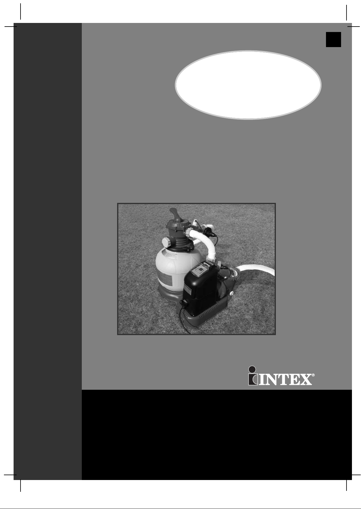
Krystal Clear
Sand Filter
Pump 14” (360mm) &
Saltwater System
Model CS15110
English
163
OOWWNNEERR’’SS MMAANNUUAALL
For illustrative purposes only.
Don’t forget to try these other fine Intex products: pools, pool accessories,
inflatable pools and in-home toys, airbeds and boats available at fine
retailers or visit our website.
IIMMPPOORRTTAANNTT!!
DO NOT RETURN PRODUCT TO STORE
To purchase parts and accessories or to obtain non-technical assistance,
Visit www.intexcorp.com
For technical assistance and missing parts call us toll-free (for U.S. and Canadian Residents):
1-800-234-6839
Monday through Friday, 8:30am to 5:00pm Pacific Time
163**-R0-1109
Page 2
(163) MODEL CS15110 SAND FILTER PUMP & FILTER PUMP ENGLISH 7.5” X 10.3” PANTONE 295U 09/18/2010
English
Warnings.......................................................................... 3
Parts List & References.................................................. 4-8
Setup Instructions ......................................................... 9-16
Product Specifications................................................... 11
Operating Instructions .................................................. 17-21
LED Code Chart.............................................................. 22
Intex Pools Salt Table...................................................... 23
Intex Pools Operating Time Table ................................. 24
163
Intex Pools Cyanuric Acid Table.................................... 25
Non-Intex Pools Salt Table.............................................. 26
Non-Intex Pools Operating Time Table.......................... 26
Non-Intex Pools Cyanuric Acid Table............................ 26
Maintenance.................................................................... 27-31
Long Term Storage.......................................................... 31
Troubleshooting Guide................................................... 32-34
Common Pool Problems................................................. 35
General Aquatic Safety................................................... 36
Limited Warranty............................................................. 37
Intex Service Center Locations..................................... 38
TTAABBLLEE OOFF CCOONNTTEENNTTSS
SAVE THESE INSTRUCTIONS
Page 2
Page 3
(163) MODEL CS15110 SAND FILTER PUMP & FILTER PUMP ENGLISH 7.5” X 10.3” PANTONE 295U 09/18/2010
English
IMPORTANT SAFETY RULES
Read, Understand and Follow All Instructions Carefully Before Installing and Using this Product.
READ AND FOLLOW ALL INSTRUCTIONS
WARNING
To reduce the risk of injury, do not permit children to use this product. Always
•
supervise children and those with disabilities.
• Children must stay away from this product and electrical cord(s).
• Assembly and disassembly by adults only.
• Risk of electric shock. Connect this product only to a grounding type receptacle
protected by a ground-fault circuit interrupter (GFCI). Contact a qualified electrician
if you cannot verify that the receptacle is protected by a GFCI.
• Always unplug this product from the electrical outlet before removing, cleaning,
servicing or making any adjustment to the product.
• Do not bury the electrical cord. Locate the cord where it will not be damaged by
lawn mowers, hedge trimmers and other equipment.
• To reduce the risk of electric shock, replace damaged cord immediately. Use a
qualified electrician to replace the cord.
• To reduce the risk of electric shock, do not use extension cords, timers, plug
adaptors or converter plugs to connect unit to electric supply; provide a properly
located outlet.
• Do not attempt to plug in or unplug this product while standing in water or when
your hands are wet.
• Do not use an appliance leakage current interrupter (ALCI) in place of a GFCI
since the ALCI will not protect people.
• Position this product away from pool, so as to prevent children from climbing on it
and access the pool.
• Do not operate this product when pool is occupied.
• To reduce the risk of entrapment hazard, never enter the pool if suction strainer
component is loose, broken, cracked, damaged or missing. Replace loose, broken,
damaged, cracked or missing suction strainer components immediately.
• Never play or swim near suction fittings. Your body or hair may be trapped causing
permanent injury or drowning.
• To prevent equipment damage and risk of injury, always turn pump off before
changing the filter control valve position.
• Never operate this product above the maximum working pressure stated on the
filter tank.
• Hazardous Pressure. Improper tank valve cover assembly could cause the valve
cover to blow off and cause serious injury, property damage or death.
• This product is intended to be used only for the purposes described in the manual!
163
SSAAFFEETTYY RRUULLEESS
FAILURE TO FOLLOW THESE WARNINGS MAY RESULT IN
PROPERTY DAMAGE, ELECTRIC SHOCK, ENTANGLEMENT OR
OTHER SERIOUS INJURY OR DEATH.
CAUTION
This product is for use with storable pools only. Do not use with permanently-installed pools. A
storable pool is constructed so that it is capable of being readily disassembled for storage and
reassembled to its original integrity. A permanently-installed pool is constructed in or on the
ground or in a building such that it cannot be readily disassembled for storage.
These product warnings, instructions and safety rules provided with the product represent
some common risks of water recreation devices and do not cover all instances of risk and
danger. Please use common sense and good judgement when enjoying any water activity.
SAVE THESE INSTRUCTIONS
Page 3
Page 4
(163) MODEL CS15110 SAND FILTER PUMP & FILTER PUMP ENGLISH 7.5” X 10.3” PANTONE 295U 09/18/2010
1
4 5
7
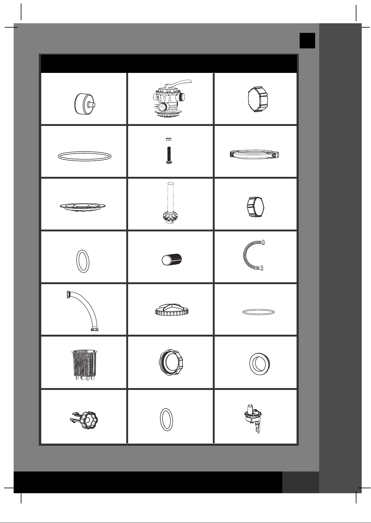
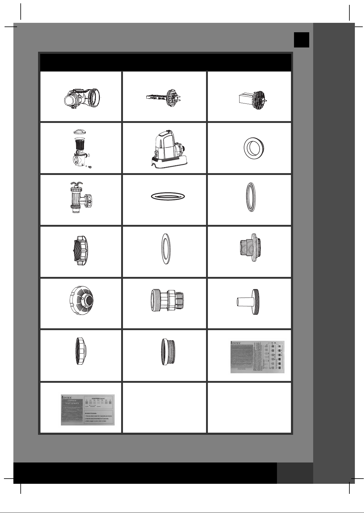
PARTS LIST
2
8
English
3
6
9
163
PPAARRTTSS LLIISSTT
10 11 12
13 14 15
16 17 18
19 20 21
NOTE: Drawings for illustration purpose only. Actual product may vary. Not to scale.
SAVE THESE INSTRUCTIONS
Page 4
Page 5
(163) MODEL CS15110 SAND FILTER PUMP & FILTER PUMP ENGLISH 7.5” X 10.3” PANTONE 295U 09/18/2010
PARTS LIST (continued)
22 2423
25 26 27
28 29 30
English
163
PPAARRTTSS LLIISSTT
31 32 33
34 35 36
37
40
38
39
NOTE: Drawings for illustration purpose only. Actual product may vary. Not to scale.
SAVE THESE INSTRUCTIONS
Page 5
Page 6
(163) MODEL CS15110 SAND FILTER PUMP & FILTER PUMP ENGLISH 7.5” X 10.3” PANTONE 295U 09/18/2010
English
163
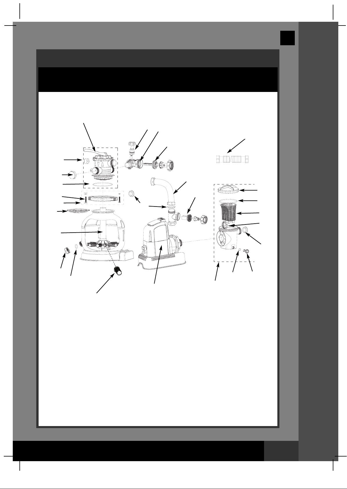
PARTS REFERENCE
efore assembling your product, please take a few minutes to check the contents
B
and become familiar with all the parts.
2
21
22
12
23
1
3
4
5
6
7
27
13
24
14
15
16
17
8
9
10
26
11
NOTE: Drawings for illustration purpose only. Actual product may vary. Not to scale.
25
20
19
18
PPAARRTTSS RREEFFEERREENNCCEE
SAVE THESE INSTRUCTIONS
Page 6
Page 7
(163) MODEL CS15110 SAND FILTER PUMP & FILTER PUMP ENGLISH 7.5” X 10.3” PANTONE 295U 09/18/2010
PARTS REFERENCE (continued)
efore assembling your product, please take a few minutes to check the contents
B
and become familiar with all the parts.
30 31 32 33 34
28
29
30 31 32 33
English
163
28
29
30 35 36 37
PPAARRTTSS RREEFFEERREENNCCEE
28
29
30 35 36 38
28
29
NOTE: Drawings for illustration purpose only. Actual product may vary. Not to scale.
SAVE THESE INSTRUCTIONS
Page 7
Page 8
(163) MODEL CS15110 SAND FILTER PUMP & FILTER PUMP ENGLISH 7.5” X 10.3” PANTONE 295U 09/18/2010
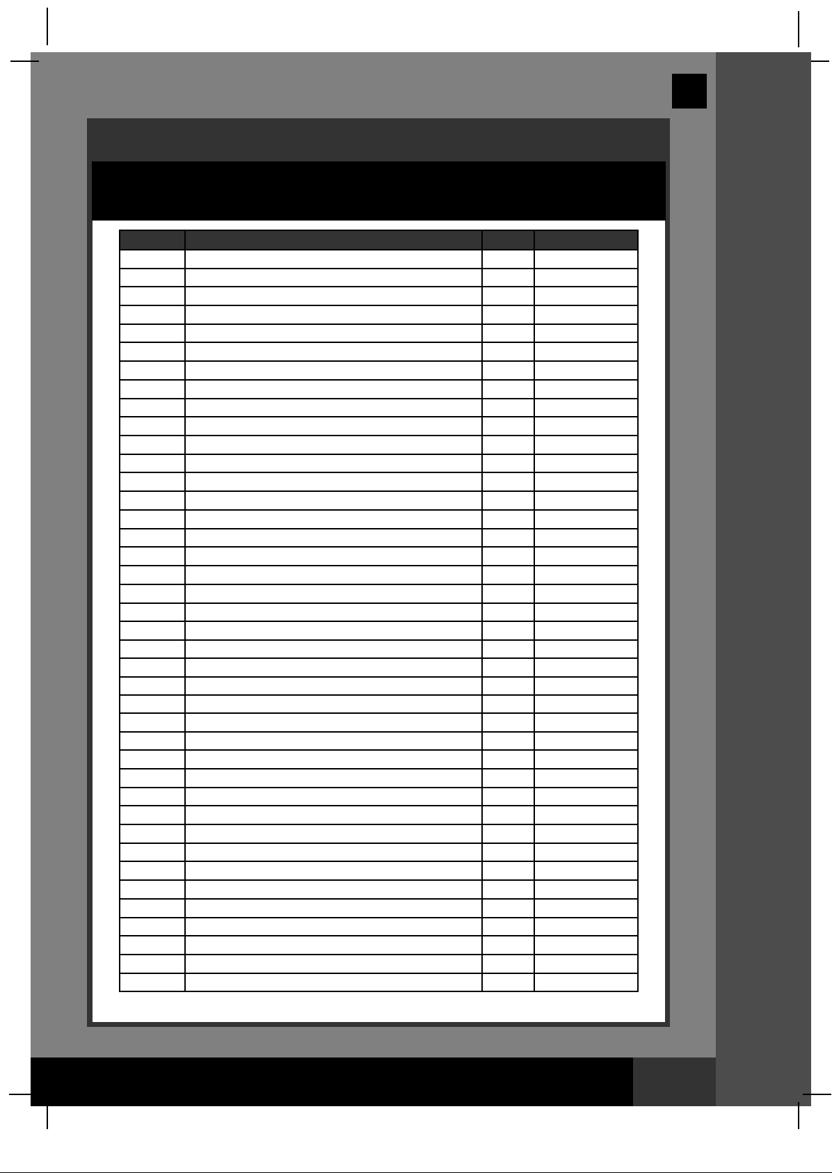
PARTS REFERENCE (continued)
Before assembling your product, please take a few minutes to check the contents
and become familiar with all the parts.
REF. NO. DESCRIPTION QTY.
1
2
3
4
5
6 CLAMP 1 11380
7
8
9
10
11 LATERAL 10 11384
12
13
14 LEAF TRAP COVER 1 11259
15 LEAF TRAP O-RING 1 11232
16 BASKET 1 11260
17 FILTER HOUSING NUT 1 11261
18
19 SEDIMENT RELEASE VALVE 1 10460
20 VALVE O-RING 1 10264
21
22
23 TITANIUM ELECTRODE 1 11389
24
25 PRE-FILTER ASSEMBLY 1 11371
26 PUMP MOTOR & CONTROL 1 11391
27
28
29
30
31
32
33
34
35
36
37
38
39 CHLORINE TEST STRIPS 1 19635
40
PRESSURE GAUGE
-WAY VALVE SET
6
DRAIN OUTLET COVER
TANK O-RING
SCREW
SAND SHIELD
CENTER PIPE HUB
DRAIN VALVE CAP
DRAIN VALVE O-RING
HOSE WITH NUTS
SAND FILTER INTERCONNECTING HOSE
L-SHAPE O-RING
FLOW SENSOR
ELECTROLYTIC CELL
COPPER ELECTRODE
L-SHAPE O-RING
PLUNGER VALVE (HOSE O-RING & STEP WASHER INCLUDED)
HOSE O-RING
STEP WASHER
STRAINER NUT
FLAT STRAINER RUBBER WASHER
THREADED STRAINER CONNECTOR
ADJUSTABLE POOL INLET NOZZLE
ADAPTOR B
STRAINER CONNECTOR
POOL INLET NOZZLE
STRAINER GRID
COPPER TEST STRIPS
When ordering parts, be sure to quote the model number and part numbers.
SPARE PART NO.
1 11411
1 11378
1 11131
1 11379
2 11381
1 11382
1 11383
1 11226
1 11385
2 11009
1 11390
1 11228
1 11373
1 11372
1 11234
4 11228
2 10747
2 10262
2 10745
2 10256
2 10255
2 11235
1 11074
2 10722
2 11070
1 11071
1 11072
1 11254
English
163
PPAARRTTSS RREEFFEERREENNCCEE
SAVE THESE INSTRUCTIONS
Page 8
Page 9

(163) MODEL CS15110 SAND FILTER PUMP & FILTER PUMP ENGLISH 7.5” X 10.3” PANTONE 295U 09/18/2010
English
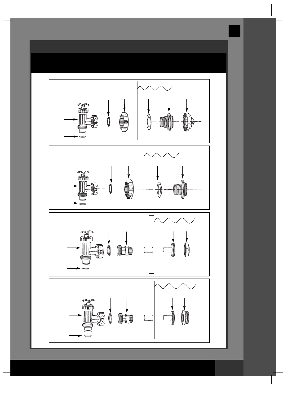
POOL OUTLET - STRAINER & PLUNGER VALVE SETUP
The strainer grid prevents large objects from jamming and/or damaging the
filter pump. If your pool has an inflatable top ring, install the strainer, nozzle
and plunger valve before inflating the pool liner top ring. The part numbers
here onward refer to the parts depicted in the Parts List section of this
manual. To install, do the following:
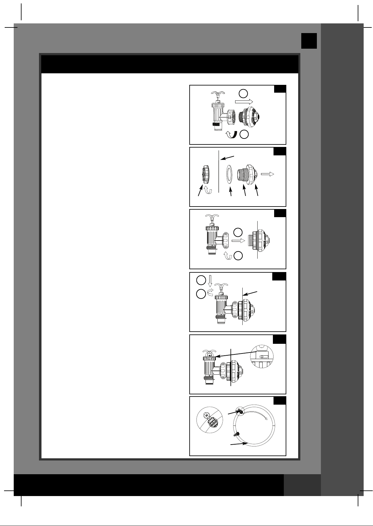
1. In a counter-clockwise motion unscrew
plunger valve union from the threaded
strainer connector (33) (see drawing 1).
Be careful not to lose the step rubber
washer (30). Place the plunger valve on
the ground in a safe place.
2. In a counter-clockwise motion unscrew the
strainer nut (31) from the threaded
connector (33). Leave the flat washer (32)
on the connector (33).
3. Install the strainer and plunger valve at the
lower position of pool outlet (marked "+").
From the inside of the pool liner insert the
connector (33) into one of the pre-cut holes
with the washer remaining on the
connector to be placed against the inside
of the liner wall.
4. Before assembly, lubricate the threads with
a petroleum jelly. With the flat side of the
strainer nut (31) facing the outside wall of
the liner in a clockwise motion screw the
strainer nut (31) back onto the threaded
connector (33) (see drawing 2).
5. Finger tighten the strainer nut (31) onto the
threaded connector (33).
6. Grasp the plunger valve assembly. Make
sure the step washer (30) is in place.
7. In a clockwise motion screw the plunger
valve union back onto the threaded
connector (33) (see drawing 3).
8. Examine the plunger valve to see if the
handle is pushed fully down to the "0/1"
position. If not, then grasp the handle at
the top and push down turning the handle
in a clockwise direction until the plastic
protruding notch anchors in the "0/1"
position. This will prevent water from
flowing out during filling (see
drawings 4.1 & 4.2).
31
2
1
2
1
2
30
INSIDE
LINER WALL
32
33
1
4.1
INSIDE
LINER
WALL
163
1
2
3
SSEETTUUPP IINNSSTTRRUUCCTTIIOONNSS
4.2
SAVE THESE INSTRUCTIONS
Page 9
Page 10
(163) MODEL CS15110 SAND FILTER PUMP & FILTER PUMP ENGLISH 7.5” X 10.3” PANTONE 295U 09/18/2010
POOL INLET - NOZZLE & PLUNGER VALVE SETUP
1. In a counter-clockwise motion unscrew
lunger valve union from the threaded
p
strainer connector (33) (see drawing 5).
Be careful not to lose the step rubber
washer (30). Place the plunger valve on
the ground in a safe place.
2. In a counter-clockwise motion unscrew the
strainer nut (31) from the threaded
connector (33). Leave the flat washer (32)
on the connector (33).
3. Install the nozzle and plunger valve at the
upper position of pool inlet. From the inside
of the pool liner insert the connector (33)
into one of the pre-cut holes with the
washer remaining on the connector to be
placed against the inside of the liner wall.
4. Before assembly, lubricate the threads with
a petroleum jelly. With the flat side of the
strainer nut (31) facing the outside wall of
the liner in a clockwise motion screw the
strainer nut (31) back onto the threaded
connector (33) (see drawing 6).
5. Finger tighten the adjustable pool inlet
nozzle (34) and the strainer nut (31) onto
the threaded connector (33).
6. Grasp the plunger valve assembly. Make
sure the step washer (30) is in place.
7. In a clockwise motion screw the plunger
valve union back onto the threaded
connector (33) (see drawing 7).
8. Examine the plunger valve to see if the
handle is pushed fully down to the "0/1"
position. If not, then grasp the handle at
the top and push down turning the handle
in a clockwise direction until the plastic
protruding notch anchors in the "0/1"
position. This will prevent water from
flowing out during filling (see
drawings 8.1 & 8.2).
9. Adjust the direction of nozzle head pointing
away from the pool outlet for a better
circulation result (see drawing 9).
10. The pool liner is now ready to fill with
water. Consult the above-ground-pool
owner’s manual for filling instructions.
31
English
2
1
INSIDE
LINER WALL
32 33 34
1
2
1
2
5
6
7
8.1
INSIDE
LINER
WALL
163
SSEETTUUPP IINNSSTTRRUUCCTTIIOONNSS
8.2
9
WATER
FLOW
SAVE THESE INSTRUCTIONS
POOL
Page 10
Page 11
(163) MODEL CS15110 SAND FILTER PUMP & FILTER PUMP ENGLISH 7.5” X 10.3” PANTONE 295U 09/18/2010
English
PRODUCT SPECIFICATIONS
The sand filter removes suspended particles and sanitize your pool. Pool
chemistry is a specialized area and you should consult your local pool
service specialist for details.
Power: 110-120 Volt AC
mperage: Saltwater System - 0.9 A; Filter Pump - 3 A
A
Wattage: Saltwater System - 100 W; Filter Pump - 370 W
Ideal Salt Level: 3000 ppm (parts per million)
Maximum Sanitizer Output/hour: 10 grams/hour
Copper Ionizer Output Current: 175mA
Maximum working pressure: 3.5 bar (50 psi)
Effective filtering area: 0.1 m
Maximum Flow Rate: 6050 liters/hour (1600 gallons/hour)
Recommended filtering media:
(Not included) range 0.45 to 0.85 mm (0.018 to 0.033
Recommended filtering media quantity: 25 Kg (55 Lbs)
Limited Warranty: 2 Years (see “Limited Warranty”)
2
(1.1 ft2)
Use only No. 20 silica sand. Particle size
inches). Uniformity Coefficient less than 1.75.
163
SETUP INSTRUCTIONS
TOOLS REQUIRED: One (1) Phillips screwdriver
Pump location and mounting:
• The system must be installed on a solid level and vibration-free base.
• Provide a location protected from the weather, moisture, flooding and
freezing temperature.
• Provide adequate access, space and lighting for routine maintenance.
• Pump motor requires free circulation of air for cooling. Do not install
the pump in a damp or non-ventilated location.
A team of 2 or more people is recommended for setting up this product.
Motor pre-filtering assembly setup:
1. Remove the sand filter and its accessories
from the packaging carefully and inspect for
any visible damage. If parts are damaged
contact your local service center listed at the
back of this owner’s manual.
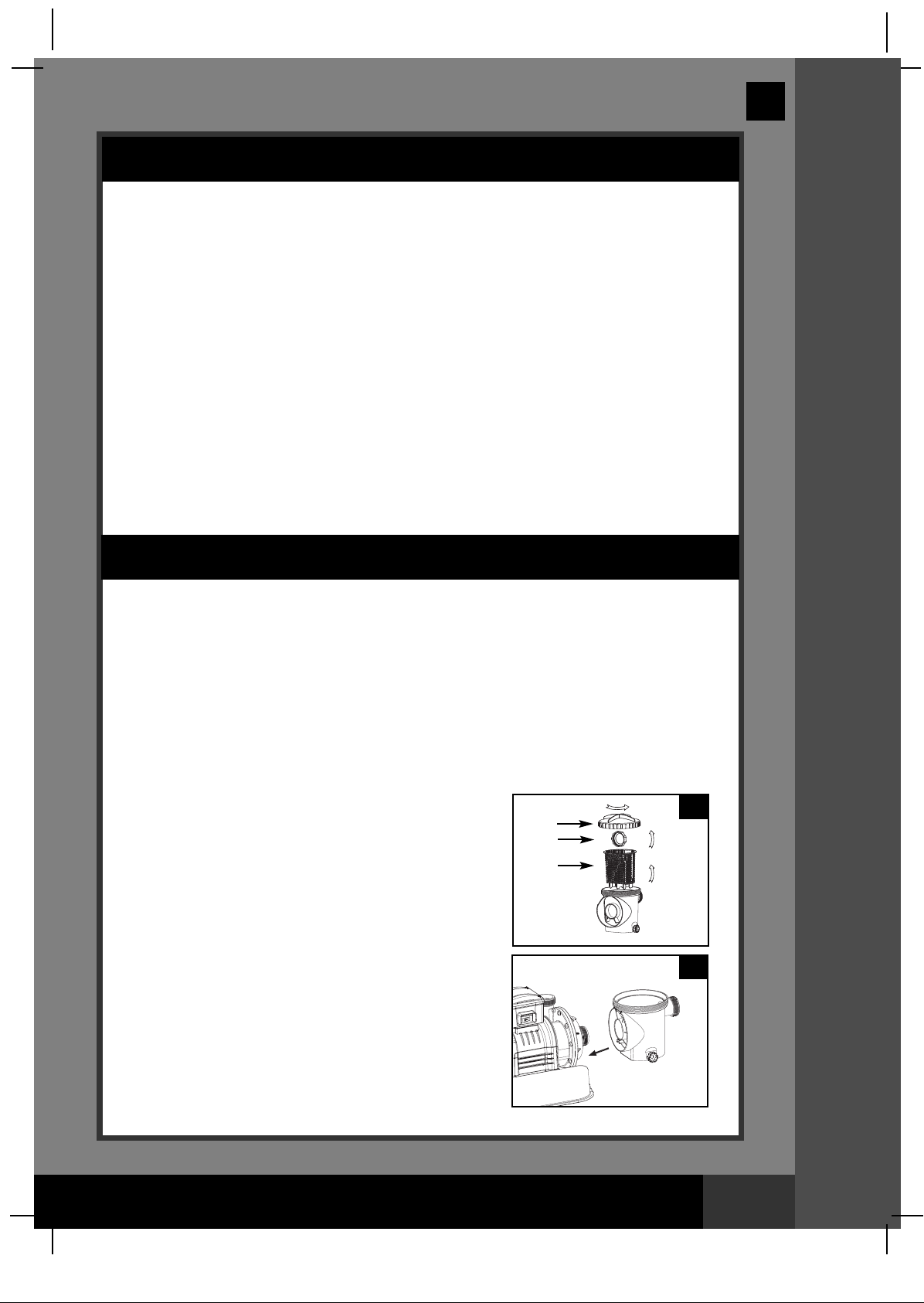
2. In a counter-clockwise motion unscrew the leaf
trap cover (14) from the pre-filter housing. Take
out the basket (16) and filter housing nut (17)
(see drawing 10).
Connect the pre-filter housing to the motor
3.
water inlet. Note: Align the connector in the
pre-filter housing with the water inlet on the
motor (see drawing 11).
14
17
16
10
11
SAVE THESE INSTRUCTIONS
PPRROODDUUCCTT SSPPEECCSS && SSEETTUUPP IINNSSTTRRUUCCTTIIOONNSS
Page 11
Page 12
(163) MODEL CS15110 SAND FILTER PUMP & FILTER PUMP ENGLISH 7.5” X 10.3” PANTONE 295U 09/18/2010
160mm
English
SETUP INSTRUCTIONS (continued)
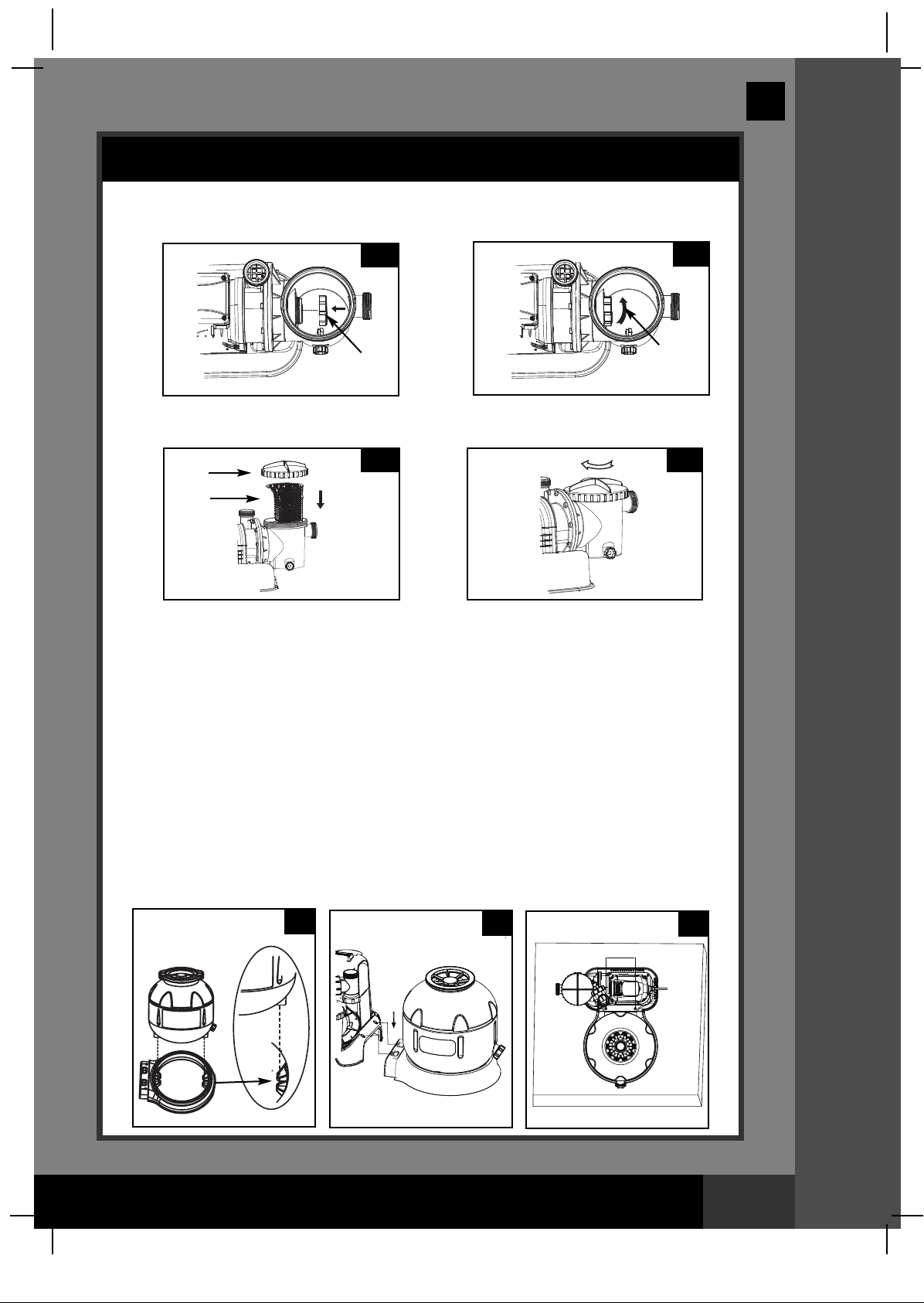
4. In a clockwise motion screw filter housing nut (17) onto the motor water inlet
(See drawings 12.1 & 12.2).
12.1
17
5. Replace the basket (16) and leaf trap cover (14) back to the pre-filter housing
(See drawings 13.1 & 13.2).
13.1 13.2
14
16
12.2
17
163
Sand tank installation:
1. Place the tank support base at the selected location.
2. Place the tank on the tank support base (See drawing 14.1).
3. Connect the motor pre-filtering assembly unit to the tank support base (See
drawing 14.2). NOTE: Ensure the pre-filter housing water inlet hose connection
is facing towards the pool.
IMPORTANT: Some countries, especially in the European community,
require the product to be secured to the ground or to a base in a
permanent upright position. Check your local authorities to determine if
there is a regulation in your area regarding above-the-ground swimming
pool filter-pumps. If yes, then the product can be mounted to a platform
using the two holes located in the base. See drawing 14.3.
The product can be mounted on a cement base or onto a wooden
platform to prevent accidental falling over.
• The mounting holes are 6.4 mm in diameter and spaced 160 mm
apart.
• Use two bolts and lock nuts with a maximum of 6.4 mm in diameter.
14.1
14.2
SSEETTUUPP IINNSSTTRRUUCCTTIIOONNSS
14.3
SAVE THESE INSTRUCTIONS
Page 12
Page 13

(163) MODEL CS15110 SAND FILTER PUMP & FILTER PUMP ENGLISH 7.5” X 10.3” PANTONE 295U 09/18/2010
MAX
MIN
MAXMAX
MINMIN
MAX
M
IN
English
SETUP INSTRUCTIONS (continued)
Sand loading:
IMPORTANT: Use only No. 20 silica sand with particle size range 0.45 to 0.85
m (0.018 to 0.033 inches) and a Uniformity Coefficient less than 1.75.
m
OTE: Before loading the tank with sand, ensure the center pipe hub
N
assembly is securely in place at the bottom of the tank, and vertically
centered inside the tank.
1. Place the sand shield (7) over the top of the center pipe. Pour the sand into the
tank at a slow rate. (see drawing 15).
2. Fill the tank approximately half way, remove the sand shield (7). (see
drawing 16).
15
7
7
16
163
3. Evenly distribute the sand inside the tank, then fill the tank with some water to
provide a cushioning effect when the remaining sand is poured in. This
prevents the center pipe hub (8) from excessive shock (see drawing 17).
Place the sand shield (7) back and continue to pour the sand into the tank.
4. Sand shall be filled between the “MAX” and “MIN” marked gauge on the center
pipe. Evenly spread and level out the sand by hand (see drawings 17 & 18).
17
8
5. Remove the sand shield (7).
6. Wash away all sand around the top edge of the tank.
8
18
SSEETTUUPP IINNSSTTRRUUCCTTIIOONNSS
SAVE THESE INSTRUCTIONS
Page 13
Page 14

(163) MODEL CS15110 SAND FILTER PUMP & FILTER PUMP ENGLISH 7.5” X 10.3” PANTONE 295U 09/18/2010
English
SETUP INSTRUCTIONS (continued)
WARNING
Improper tank valve and clamp assembly could cause the valve and clamp
to blow off and cause serious injury, property damage or death.
6-way valve installation:
1. Lower the 6-way valve over the tank slowly, and ensure the bypass pipe protruding
underneath the 6-way valve fits securely into the center pipe hub (8) top opening (see
drawing 19).
MPORTANT: There are three hose connection ports on the 6-way valve, ensure
I
the outlet connection (from filter to the pool) on the valve is facing towards the
pool, and the inlet connection (from motor to valve) is aligned with the motor
outlet (see drawing 20).
2. Remove the clamp bolt, and install the clamp around the tank and 6-way valve flanges,
then replace the clamp bolt and use a phillips screwdriver (not included) to tighten it.
(see drawing 21).
19
WATER
INLET
20
WATER
OUTLET
21
6
163
8
3. Connect the sand filter interconnecting hose (13) between the 6-way valve inlet and
motor outlet, and insert the electrolytic cell (22) into the 6-way valve outlet. Hand tighten
them securely (see drawings 22 and 23).
22
13
22
4. Screw and tighten the flow sensor (21) to the electrolytic cell (22), then plug in the
electrolytic cell line cord and tighten the nut (see drawings 24 and 25).
21
22
24
23
SSEETTUUPP IINNSSTTRRUUCCTTIIOONNSS
25
SAVE THESE INSTRUCTIONS
Page 14
Page 15

(163) MODEL CS15110 SAND FILTER PUMP & FILTER PUMP ENGLISH 7.5” X 10.3” PANTONE 295U 09/18/2010
English
SAND FILTER PUMP HOSE CONNECTION SETUP
WARNING
Position this product away from the pool, so as to prevent children from
•
climbing on it and accessing the pool.
The 6-way valve has three hose connection ports.
1. Connect one hose (12) end to the pre-filter inlet and the other end of the hose
to the lower plunger valve with the strainer. Ensure the hose nuts are securely
tighten.
2. Connect the second hose (12) between the electrolytic cell outlet and the
upper plunger valve with the inlet-nozzle. Ensure the hose nuts are securely
tighten.
3. The third hose connection port (drain/waste outlet) on the 6-way valve shall be
directed to a proper draining receptacle using a hose or pipe (not provided).
Remove the drain cap before attaching the drain/waste hose or pipe.
4. The sand filter pump is now ready to filter the pool.
163
TO
DRAIN
6-WAY VALVE
WATER LEVEL
PLUNGER
VALVE
OUTSIDE
LINER WALL
(ILLUSTRATION NOT TO SCALE)
ADJUSTABLE
POOL INLET
NOZZLE
THREADED
STRAINER
CONNECTOR
SSEETTUUPP IINNSSTTRRUUCCTTIIOONNSS
SAVE THESE INSTRUCTIONS
Page 15
Page 16

(163) MODEL CS15110 SAND FILTER PUMP & FILTER PUMP ENGLISH 7.5” X 10.3” PANTONE 295U 09/18/2010
English
SAND FILTER PUMP HOSE CONNECTION SETUP (continued)
For NON-INTEX pool:
1. Connect the hose (12) to the pool inlet/outlet connection with a large hose
clamp. Tighten securely. Remove the drain valve (3) from the 6-way valve
utlet and connect the hose to the outlet.
o
12
LARGE HOSE
CLAMP
3
POOL
163
For INTEX pool size 16' and below:
1. In a counter-clockwise motion unscrew plunger valve union from the threaded
strainer connector (25). Be careful not to lose the step rubber washer (22).
2. Grasp the plunger valve assembly. Make sure the step washer (22) is in place.
Connect adaptor B (27) to plunger valve union.
3. Remove wall plug and then insert the strainer (28 & 30) into the lower position
of protruding hose connection, and the nozzle (28 & 29) into the upper position
of protruding hose connection. Adaptor B (27) fits over the strainer
connection (28) inserted into the connection. Tighten securely.
4. Remove the drain valve (3) from the 6-way valve outlet and connect the hose
to the outlet.
28 & 29
3
28 & 30
POOL
SSEETTUUPP IINNSSTTRRUUCCTTIIOONNSS
SAVE THESE INSTRUCTIONS
Page 16
Page 17

(163) MODEL CS15110 SAND FILTER PUMP & FILTER PUMP ENGLISH 7.5” X 10.3” PANTONE 295U 09/18/2010
R
E
T
L
I
F
E
S
N
I
R
ET
A
L
U
C
RI
C
E
R
E
S
O
L
C
ETSA
W
E
S
N
I
R
ETALU
C
RICER
H
S
A
W
K
C
A
B
E
S
O
L
C
E
TSAW
R
E
T
L
I
F
E
S
N
I
R
E
TALU
C
RICER
H
S
A
W
K
C
A
B
ETSA
W
B
E
S
N
I
R
ETALU
C
RICER
H
S
A
W
K
C
A
B
E
S
O
L
C
E
TSAW
R
E
T
L
I
F
E
S
N
I
R
E
TALU
C
RICER
H
S
A
W
K
C
A
B
ETSA
W
R
E
T
L
I
F
E
S
N
I
R
E
TALU
C
RICER
H
S
A
W
K
C
A
B
ETSA
W
English
OPERATING INSTRUCTIONS
WARNING
• Risk of electric shock. Connect this product only to a grounding type
eceptacle protected by a ground-fault circuit interrupter (GFCI) or
r
residual current device (RCD). Contact a qualified electrician if you cannot
verify that the receptacle is protected by a GFCI/RCD. Use a qualified
electrician to install the GFCI/RCD, which has a maximum rate of 30mA.
Do not use a portable residual current device (PRCD).
• To reduce the risk of electric shock, do not use extension cords, timers,
plug adaptors or converter plugs to connect unit to electric supply;
provide a properly located outlet.
• Do not attempt to plug in or unplug this product while standing in water
or when your hands are wet.
• Never operate this product above the maximum working pressure stated
on the filter tank.
• Always switch off pump before changing the 6-way valve position.
• Operating this product without water flowing through the system can
cause a build up of hazardous pressure which can result in an explosive
situation, serious injury, property damage or death.
• Never test this pump with compressed air. Never operate the system with
water temperature above 35° C (95° F).
163
6-way valve positions and function:
Valve Position Function Water Flow Direction
FILTER
(see drawing 27)
BACKWASH
(see drawing 28)
RINSE
(see drawing 29)
WASTE
(see drawing 30)
RECIRCULATE
(see drawing 31)
CLOSED
(see drawing 32)
Normal filtration and regular
vacuuming of pool
Reverses water flow to clean
filter media
For initial startup cleaning of the sand, and
leveling the sand bed after backwashing
For vacuuming directly to waste,
lowering pool level or to drain the pool
For circulating water back to pool
without going through the filter media
Shuts off all flow to filter and pool
“Do not use this setting with pump running”
27
From pump through filter media
to pool
From pump through filter media
to valve waste/drain outlet
From pump through filter media
to valve waste/drain outlet
From pump to valve waste/drain
outlet bypassing the filter media
From pump through valve to
pool bypassing the filter media
28
29
OOPPEERRAATTIINNGG IINNSSTTRRUUCCTTIIOONNSS
SAVE THESE INSTRUCTIONS
Page 17
Page 18

(163) MODEL CS15110 SAND FILTER PUMP & FILTER PUMP ENGLISH 7.5” X 10.3” PANTONE 295U 09/18/2010
R
E
T
L
I
F
E
S
N
I
R
ET
A
L
U
C
RI
C
E
R
E
S
O
L
C
ETSA
W
E
S
N
I
R
ETALU
C
RICER
H
SA
W
K
C
A
B
E
S
O
L
C
E
TSAW
R
E
T
L
I
F
E
S
N
I
R
E
TALU
C
RICER
H
S
A
W
K
C
A
B
ETSA
W
R
E
T
L
I
F
E
S
N
I
R
ER
H
S
A
W
K
C
A
B
E
S
O
L
C
ETSAW
R
E
T
L
I
F
ES
N
I
R
E
TA
L
U
C
R
I
CE
R
H
S
A
W
K
C
A
B
E
S
O
L
C
R
E
T
L
I
F
ETALUC
R
ICER
H
S
A
W
K
C
A
B
E
S
O
L
C
ETSAW
B
E
S
N
I
R
ETALU
C
RICER
H
SA
W
K
C
A
B
E
S
O
L
C
E
TSAW
R
E
T
L
I
F
E
S
N
I
R
E
TALU
C
RICER
H
S
A
W
K
C
A
B
ETSA
W
R
E
T
L
I
F
ES
N
I
R
E
TA
L
U
C
R
I
CE
R
H
S
A
W
K
C
A
B
E
S
O
L
C
R
E
T
L
I
F
ETALUC
R
ICER
H
S
A
W
K
C
A
B
E
S
O
L
C
ETSAW
R
E
T
L
I
F
E
S
N
I
R
E
TALU
C
RICER
H
S
A
W
K
C
A
B
ETSA
W
R
E
T
L
I
F
ETALUC
R
ICER
H
S
A
W
K
C
A
B
E
S
O
L
C
ETSAW
English
OPERATING INSTRUCTIONS (continued)
30
Initial startup and operation:
Before operating, be sure that:
• All the hoses have been connected and tightened securely, and correct amount
of filter sand have been loaded.
• The entire system is connected to a grounding type receptacle protected by a
ground-fault circuit interrupter (GFCI) or residual current device (RCD).
31
CAUTION
163
32
The filter control valve has a closed position. The pump should never be
on when the valve is in the closed position. If the pump is operated with
the valve closed, and explosive situation could exist.
1. Grasp a plunger valve handle. Turn the handle counter-clockwise, pull up until it
stops, and then turn it clockwise until the metal protruding notch anchor is in
the "0/1" position. Repeat for the second plunger valve. This opens the valves to
allow water to flow into the sand filter pump.
2. Ensure the drain/waste outlet on the 6-way valve is not covered and directed to
a proper draining receptacle.
3. Ensure the pump is off, depress the 6-way
33
valve and turn it to the “BACKWASH” position
(see drawings 28 & 33).
IMPORTANT: To prevent damage to the
2
1
6-way valve, always depress the valve
handle before turning. Always switch off
pump before changing the 6-way valve
position.
4. Switch on the pump (see drawing 34). Water
is circulating backward through the sand
media and to waste/drain outlet. Backwash
until a clear flow of water is observed in the
waste/drain outlet or through the drain sediment
ON
OFF
34
OOPPEERRAATTIINNGG IINNSSTTRRUUCCTTIIOONNSS
window.
NOTE: The initial backwash of the filter is
recommended to remove any impurities or fine
sand particles in the sand media.
SAVE THESE INSTRUCTIONS
Page 18
Page 19

(163) MODEL CS15110 SAND FILTER PUMP & FILTER PUMP ENGLISH 7.5” X 10.3” PANTONE 295U 09/18/2010
English
OPERATING INSTRUCTIONS (continued)
. Switch off the pump, change the 6-way valve to “RINSE” position (see
5
drawing 29).
. Switch on the pump and run the pump for about one minute to level out the
6
sand bed after backwashing the sand media.
7. Switch off the pump, change the 6-way valve to “FILTER” position (see
drawing 27).
8. Switch on the pump. The system is now operating in the normal filtering mode.
Run the pump until the desired pool water clearance is obtained and no more
than 12 hours per day.
9. Record the initial pressure gauge reading when the filter media is clean.
NOTE: During initial setup of the system, it may be necessary to backwash
frequently due to unusual heavy dirt present in the water and sand. After that,
as the filter removes dirt and impurities from the pool water, the accumulated
dirt in the sand media will cause the pressure to rise and the flow to diminish. If
there is no vacuuming device attached to the system and the pressure gauge
reading is in the yellow zone it is time to backwash the sand media, see
“BACKWASH” under “initial startup and operation” section.
Vacuuming device (i.e. Intex auto pool cleaner) attached to the system may also
cause the flow to diminish and the pressure to rise. Remove any vacuuming
device from the system and check if the pressure gauge reading has dropped
from the yellow zone to the green zone.
163
Operation is subject to the following two conditions: (1) this device may not cause
interference, and (2) this device must accept any interference, including
interference that may cause undesired operation of the device.
Changes or modifications not expressly approved by the party responsible for
compliance could void the user’s authority to operate the equipment.
This equipment has been tested and found to comply with the limits for Class B
digital device, pursuant to part 15 of the FCC Rules. These limits are designed to
provide reasonable protection against harmful interference in a residential
installation. This equipment generates, uses and can radiate radio frequency
energy and, if not installed and used in accordance with the instructions, may
cause harmful interference to radio or television reception, which can be
determined by turning the equipment off and on, the user is encouraged to try to
correct the interference by one or more of the following measures:
• Reorient or relocate the receiving antenna.
• Increase the separation between the equipment and the receiver.
• Connect the equipment into an outlet on a circuit different from that to which the
receiver is connected.
• Consult the dealer or an experienced radio/TV technician for help.
OOPPEERRAATTIINNGG IINNSSTTRRUUCCTTIIOONNSS
SAVE THESE INSTRUCTIONS
Page 19
Page 20

(163) MODEL CS15110 SAND FILTER PUMP & FILTER PUMP ENGLISH 7.5” X 10.3” PANTONE 295U 09/18/2010
OK
0
Copper (ppm)
0.1 0.2 0.5 0.9 1.3
SALTWATER SYSTEM OPERATION
1. Start up the unit:
Plug the power cord into the electrical outlet and test the GFCI/RCD (circuit
reaker). Switch on the unit.
b
With the Filter Pump turned “ON” and operating. The green "Pump" light on the
control panel will be on and code “00” appears on the electronic control
station’s LED, indicating that the unit is in a Stand-By Mode. This is normal.
2. Unlock keypad controls:
Press and hold the button for 2 seconds until you hear a
short “beep”. Then press and hold the button for another 2
seconds until you hear the second short “beep”. The LED
flashes “00”. This procedure unlocks the keypad control
buttons.
3. Set operating hours for Saltwater System:
Increase the scheduled number of operating
hours by pressing the button . Or reduce
them by pressing the button . See the
“Operating Time Table” for the required
operating hours related to each pool size.
Press the button to select the desired
hours. You can press if you have
selected too many hours. The built-in timer
will now activate your Saltwater System, at
the same time each day, for the number of hours you have set.
NOTE: The Saltwater System will not operate if the filter pump is not operating.
(1 to 12 hours max per cycle)
English
163
4. Lock keypad controls:
Wit h the desired hour value showing, press and hold the
button for 2 seconds until you hear a long “beep”. Then press
and hold for another 2 seconds until you hear the second
long “beep”. The green “WORKING” indicator on the control
panel will light up within a few seconds to indicate that the
saltwater system has started sanitizer production. Locking the
control buttons into this setting prevents unauthorized changing
of the operating cycle.
NOTE: If you forget to lock the keypad controls, the system will
automatically lock it and start working 1 minute later.
5. Readjust operating time if necessary:
The operating hours can be re-adjusted if necessary. Just repeat the steps 2
through 4.
6. Test the copper concentration in the
pool water.
The Saltwater System recommends a
copper level of 0.1 to 0.2 ppm. This is
easily tested by the copper ion test strips
provided. If the test result is 0.1~0.2ppm,
go directly to step 8.
OOPPEERRAATTIINNGG IINNSSTTRRUUCCTTIIOONNSS
SAVE THESE INSTRUCTIONS
Page 20
Page 21

(163) MODEL CS15110 SAND FILTER PUMP & FILTER PUMP ENGLISH 7.5” X 10.3” PANTONE 295U 09/18/2010
English
SALTWATER SYSTEM OPERATION (continued)
7. Boost cycle
• If the test result is below 0.1ppm, press and hold “BOOST”
button for 5 seconds until the indicator lights up and the
LED display display “80”. This indicates that the saltwater
system has started copper ion production.
ou can press and hold the “BOOST” button for another 5
Y
seconds until the indicator is off, which will cancel the Boost
cycle.
Note: Once the system has started copper ion production, the
boost button can’t be re-set until the power switch is off.
• The boost operating hours is 4 times the amount of time programmed into the
system, i.e. if your saltwater system operating time is 2 hours, the boost procedure
will run 4 x 2 = 8 hours. After boost procedure has been completed, the system
will automatically switch to the normal working mode.
• After a heavy rain or if the pool is dirty, press the “BOOST” button to shock the
pool again.
8. Test pool water regularly:
Once the copper level appears to be balanced, test the pool water every week
to maintain the proper sanitizer level.
It’s very important that the free chlorine is between 0.4-1.5 ppm and copper
ion concentration is between 0.1~0.2 ppm. When the copper level is below 0.1
ppm, repeat step 7.
NOTE: A High copper ion concentration may cause blonde hair to exhibit a
green hair. To prevent this, wear a swimming cap during swimming, and wash
hair with special shampoo after using the pool.
See “Troubleshooting Guide”.
163
9. Stand-by/power saving mode:
• When the cycle ends, the green “SLEEP” indicator on the
control panel lights up and the LED display flashes “93”.
The system is now in Stand-By mode. After a while, it
shuts down and sets itself in a Power Saving mode. The
system will automatically turn itself back on in 24 hours,
starting its daily cycle of chlorine production.
• The “SLEEP” indicator stays on, while the system is in the
Power Saving mode. The LED display however, goes blank
after 1 hour. Press any button ( or ) to view the last LED
code.
10. Running the pump alone without the Saltwater System:
To run the pump alone without the Saltwater System function,
press and hold both ( ) and ( ) buttons for 5 seconds
until you hear a “beep” and the LED display shows “FP”.
The pump is now operating alone. To stop the pump,
manually turn the switch OFF. NOTE: The pump cannot
be operated alone under an automatic timer mode.
IMPORTANT: To keep the initial automatic operating cycle
setting of the Saltwater System, turn the switch ON, the
LED display shows “FP”, then unlock and lock the keypad
controls again, see previous steps 2 and 4. The LED display
shows the initial input hours and the Saltwater System cycle
repeats again.
OOPPEERRAATTIINNGG IINNSSTTRRUUCCTTIIOONNSS
SAVE THESE INSTRUCTIONS
Page 21
Page 22

(163) MODEL CS15110 SAND FILTER PUMP & FILTER PUMP ENGLISH 7.5” X 10.3” PANTONE 295U 09/18/2010
LED CODE CHART
ED Reading
L
FP Filter Pump Working Mode
0 Boost Mode
8
00 Stand-By Mode (Start-up)
01 Minimum Operating Hour (1 hour remaining)
02 Operating Hours (2 hours remaining)
03 Operating Hours (3 hours remaining)
04 Operating Hours (4 hours remaining)
05 Operating Hours (5 hours remaining)
06 Operating Hours (6 hours remaining)
07 Operating Hours (7 hours remaining)
08 Operating Hours (8 hours remaining)
09 Operating Hours (9 hours remaining)
10 Operating Hours (10 hours remaining)
11 Operating Hours (11 hours remaining)
12 Maximum Operating Hours (12 hours remaining)
90 Alarm Code (Low Water Flow / No Flow)
91 Alarm Code (Low Salt Level)
92 Alarm Code (High Salt Level)
93 Stand-By Mode (Operating Process finished)
“BLANK” No Power or “Power Saving Mode” waiting to start next
Saltwater System cycle.
efinitions
D
English
163
LLEEDD CCOODDEE CCHHAARRTT
SAVE THESE INSTRUCTIONS
Page 22
Page 23

(163) MODEL CS15110 SAND FILTER PUMP & FILTER PUMP ENGLISH 7.5” X 10.3” PANTONE 295U 09/18/2010
English
INTEX POOLS SALT TABLE
This table shows the dosage of salt needed to achieve and maintain the optimal 3000 ppm salt
evel.
l
Pool Size
INTEX ABOVE GROUND POOLS (AGP’s)
15' x 33" (457cm x 84cm)
15' x 36" (457cm x 91cm)
15' x 42" (457cm x 107cm)
EASY SET
POOL
CIRCULAR
METAL
FRAME POOL
ULTRA FRAME
POOL
SEQUOIA SPIRIT™
POOL SET
OVAL FRAME
POOL
RECT. ULTRA
FRAME POOL
®
15' x 48" (457cm x 122cm)
16' x 42" (488cm x 107cm)
16' x 48" (488cm x 122cm)
18' x 42" (549cm x 107cm)
18' x 48" (549cm x 122cm)
18' x 52" (549cm x 132cm)
15' x 36" (457cm x 91cm)
15' x 42" (457cm x 107cm)
15' x 48" (457cm x 122cm)
16' x 48" (488cm x 122cm)
18' x 48" (549cm x 122cm)
18' x 52" (549cm x 132cm)
20' x 52" (610cm x 132cm)
24' x 48" (732cm x 122cm)
16' x 48" (488cm x 122cm)
18' x 52" (549cm x 132cm)
16'8" x 49" (508cm x 124cm)
18'8" x 53" (569cm x 135cm)
18' x 10' x 42" (549cm x 305cm x 107cm)
20' x 12' x 48" (610cm x 366cm x 122cm)
24' x 12' x 48" (732cm x 366cm x 122cm)
18' x 9' x 52" (549cm x 274cm x 132cm)
24' x 12' x 52" (732cm x 366cm x 132cm)
Water Capacity (Calculated at
90% for Frame Pool and 80%
for Easy Set & Oval Pool)
(Gals)
2587 9792 65 30 15 10
2822 10681 65 30 20 10
3284 12430 80 35 20 10
3736 14141 95 45 25 10
3754 14209 95 45 25 10
4273 16173 110 50 30 15
4786 18115 120 55 30 15
5455 20647 135 60 35 15
5894 22309 150 65 40 20
3282 12422 80 35 20 10
3861 14614 100 45 25 10
4440 16805 110 50 30 15
5061 19156 125 55 35 15
6423 24311 160 75 40 20
6981 26423 175 80 45 20
8638 32695 220 100 60 25
11483 43462 290 130 75 35
5061 19156 125 55 35 15
6981 26423 175 80 45 20
5061 19156 125 55 35 15
6981 26423 175 80 45 20
2885 10920 65 30 20 10
4393 16628 110 50 30 15
5407 20465 135 60 35 15
4545 17203 115 50 30 15
8403 31805 210 100 55 25
(Liters) (Lbs) (Kgs) (Lbs) (Kgs)
Salt Needed for
Startup
3.0g/L (3000ppm)
Salt Needed when
Low Salt Detected
(CODE “91”)
163
SAVE THESE INSTRUCTIONS
Page 23
Page 24

(163) MODEL CS15110 SAND FILTER PUMP & FILTER PUMP ENGLISH 7.5” X 10.3” PANTONE 295U 09/18/2010
INTEX POOLS OPERATING TIME TABLE (WITH CYANURIC ACID)
Operating Time (hours)
at different ambient/air
temperatures
10 - 19°C
(50 - 66°F)
1
1
1
2
2
2
2
3
3
1
2
2
3
3
4
4
7
3
4
3
4
1
2
3
2
5
Pool Size
INTEX ABOVE GROUND POOLS (AGP’s)
15' x 33" (457cm x 84cm)
15' x 36" (457cm x 91cm)
15' x 42" (457cm x 107cm)
EASY SET
POOL
CIRCULAR
METAL
FRAME POOL
ULTRA FRAME
POOL
SEQUOIA SPIRIT
POOL SET
OVAL FRAME
POOL
RECT. ULTRA
FRAME POOL
®
®
®
15' x 48" (457cm x 122cm)
16' x 42" (488cm x 107cm)
16' x 48" (488cm x 122cm)
18' x 42" (549cm x 107cm)
18' x 48" (549cm x 122cm)
18' x 52" (549cm x 132cm)
15' x 36" (457cm x 91cm)
15' x 42" (457cm x 107cm)
15' x 48" (457cm x 122cm)
16' x 48" (488cm x 122cm)
18' x 48" (549cm x 122cm)
18' x 52" (549cm x 132cm)
20' x 52" (610cm x 132cm)
24' x 48" (732cm x 122cm)
16' x 48" (488cm x 122cm)
18' x 52" (549cm x 132cm)
16'8" x 49" (508cm x 124cm)
569
18'8" x 53" (
18' x 10' x 42" (549cm x 305cm x 107cm)
20' x 12' x 48" (610cm x 366cm x 122cm)
24' x 12' x 48" (732cm x 366cm x 122cm)
18' x 9' x 52" (549cm x 274cm x 132cm)
24' x 12' x 52" (732cm x 366cm x 132cm)
cm x 135cm)
Water Capacity (Calculated at
90% for Frame Pool and 80% for
Easy Set & Oval Pool)
(Gals) (Liters)
2587
2822
3284
3736
3754
4273
4786
5455
5894
3282
3 861
4440
5061
6423
6981
8638
11483
5061
6981
5061
6981
2885
4393
5407
4545
8403
9792
10681
12430
14141
14209
16173
18115
20647
22309
12422
14614
16805
19156
24311
26423
32695
43462
19156
26423
19156
26423
10920
16628
20465
17203
31805
English
20 - 28 °C
(68 - 82 °F)
1
1
2
2
2
3
3
3
3
1
2
3
3
4
4
5
7
3
4
3
4
1
3
3
3
5
29 - 36 °C
(84 - 97 °F)
2
2
2
3
3
3
3
4
4
2
3
3
4
5
5
6
8
4
5
4
5
2
3
4
3
6
163
SAVE THESE INSTRUCTIONS
Page 24
Page 25

(163) MODEL CS15110 SAND FILTER PUMP & FILTER PUMP ENGLISH 7.5” X 10.3” PANTONE 295U 09/18/2010
English
INTEX POOLS CYANURIC ACID TABLE
Cyanuric acid is a chemical that reduces the loss of chlorine in water due to ultraviolet rays. To
maintain maximum performance, we recommend that the cyanuric acid level be maintained at
pproximately 1% of the salt, i.e. 100 Lbs (45 Kgs) salt x1% = 1 Lbs (0.45 Kgs) cyanuric acid.
a
Cyanuric Acid Needed for
Startup
0.03g/L (30ppm)
Lbs)
(
Kgs)
(
Pool Size
INTEX ABOVE GROUND POOLS (AGP’s)
15' x 33" (457cm x 84cm)
15' x 36" (457cm x 91cm)
15' x 42" (457cm x 107cm)
EASY SET
POOL
CIRCULAR
METAL
FRAME POOL
ULTRA FRAME
POOL
SEQUOIA SPIRIT
POOL SET
OVAL FRAME
POOL
RECT. ULTRA
FRAME POOL
®
®
®
15' x 48" (457cm x 122cm)
16' x 42" (488cm x 107cm)
16' x 48" (488cm x 122cm)
18' x 42" (549cm x 107cm)
18' x 48" (549cm x 122cm)
18' x 52" (549cm x 132cm)
15' x 36" (457cm x 91cm)
15' x 42" (457cm x 107cm)
15' x 48" (457cm x 122cm)
16' x 48" (488cm x 122cm)
18' x 48" (549cm x 122cm)
18' x 52" (549cm x 132cm)
20' x 52" (610cm x 132cm)
24' x 48" (732cm x 122cm)
16' x 48" (488cm x 122cm)
18' x 52" (549cm x 132cm)
16'8" x 49" (508cm x 124cm)
569
18'8" x 53" (
18' x 10' x 42" (549cm x 305cm x 107cm)
20' x 12' x 48" (610cm x 366cm x 122cm)
24' x 12' x 48" (732cm x 366cm x 122cm)
18' x 9' x 52" (549cm x 274cm x 132cm)
24' x 12' x 52" (732cm x 366cm x 132cm)
cm x 135cm)
Water Capacity (Calculated at
90% for Frame Pool and 80%
for Easy Set & Oval Pool)
(Gals)
2587 9792 0.6 0.3
2822 10681 0.7 0.3
3284 12430 0.8 0.4
3736 14141 0.9 0.4
3754 14209 0.9 0.4
4273 16173 1.1 0.5
4786 18115 1.2 0.5
5455 20647 1.4 0.6
5894 22309 1.5 0.7
3282 12422 0.8 0.4
3861 14614 1.0 0.4
4440 16805 1.1 0.5
5061 19156 1.3 0.6
6423 24311 1.6 0.7
6981 26423 1.7 0.8
8638 32695 2.2 1.0
11483 43462 2.9 1.3
5061 19156 1.3 0.6
6981 26423 1.7 0.8
5061 19156 1.3 0.6
6981 26423 1.7 0.8
2885 10920 0.7 0.3
4393 16628 1.1 0.5
5407 20465 1.4 0.6
4545 17203 1.1 0.5
8403 31805 2.1 1.0
Liters)
(
163
SAVE THESE INSTRUCTIONS
Page 25
Page 26

(163) MODEL CS15110 SAND FILTER PUMP & FILTER PUMP ENGLISH 7.5” X 10.3” PANTONE 295U 09/18/2010
SALT CALCULATION FORMULA FOR ALL POOLS
Salt Needed for Startup
(Lbs)
Water Capacity (Gals) x 0.025
Salt Needed for Startup
(Kgs)
Water Capacity (Liters) x 0.003
Salt Needed when
Low Salt Detected (Lbs)
Water Capacity (Gals) x 0.0067 Water Capacity (Liters) x 0.0008
Salt Needed when
Low Salt Detected (Kgs)
SALT TABLE FOR COMMON NON-INTEX POOLS
Salt Needed when
ater Capacity
W
(Gals) (Liters) (Lbs) (Kgs) (Lbs) (Kgs)
2000 7500 50 20 10 5
4000 15000 100 45 25 10
6000 22500 150 65 40 20
8000 30000 200 90 55 25
10000 37500 250 110 70 30
12000 45500 300 135 80 35
14000 53000 350 160 95 45
alt Needed for Startup
S
ow Salt Detected
L
(CODE “91”)
English
163
OPERATING TIME TABLE FOR COMMON NON-INTEX POOLS
Water Capacity
(Gals) (Liters)
2000
4000
6000
8000
10000
12000
14000
7500
15000
22500
30000
37500
45500
53000
10 - 19°C
(50 - 66°F)
1
2
3
5
6
7
9
Operating Time (hours)
at different ambient/air temperatures
20 - 28 °C
(68 - 82 °F)
1
2
3
5
6
8
9
29 - 36 °C
(84 - 97 °F)
CYANURIC ACID TABLE FOR COMMON NON-INTEX POOLS
Water Capacity
(Gals) (Liters) (Lbs) (Kgs)
2000
4000
6000
8000
10000
12000
14000
7500
15000
22500
30000
37500
45500
53000
Cyanuric Acid Needed for Startup
0.5
1.0
1.5
2.0
2.5
3.0
3.5
0.03g/L (30ppm)
0.23
0.45
0.68
0.90
1.13
1.37
1.59
1
3
4
6
7
9
10
SAVE THESE INSTRUCTIONS
Page 26
Page 27

(163) MODEL CS15110 SAND FILTER PUMP & FILTER PUMP ENGLISH 7.5” X 10.3” PANTONE 295U 09/18/2010
1
2
English
MOTOR PRE-FILTER CLEANING AND MAINTENANCE
1. Make sure the filter pump is switched off, then disconnect the power cord from
the electrical outlet.
2. Grasp a plunger valve handle. Turn the handle counter-clockwise, push down
until it stops and then turn it clockwise until the plastic protruding notch anchors
in the "0/1" position. Repeat for the second plunger valve. This prevents the
water from flowing out of the pool.
3. Release the pressure first by opening the
sediment release valve (19) located
on the lower side of the pre-filter housing
(see drawing 35).
4. In a counter-clockwise motion unscrew the
leaf trap cover (14), then remove the
basket (16) and leaf trap o-ring (15) from the
pre-filter housing (see drawing 36).
5. Empty and flush the basket using a garden
hose, may use a plastic brush to remove
deposits from the basket. Do not use metal
brush.
6. Clean and rinse the inside of the pre-filter
housing and the leaf trap O-ring with
a garden hose.
7. Reinstall the leaf trap O-ring, basket and leaf
trap cover to the pre-filter housing.
8. Close the sediment release valve (19) back.
14
16
15
19
163
35
36
MMAAIINNTTEENNAANNCCEE
FFLLOOWW SSEENNSSOORR CCLLEEAANNIINNGG
1. In a counter-clockwise motion unscrew the collar of the flow sensor (21)
and remove it from the electrolytic cell conduit (22). See “Part Reference”.
2. If deposits and debris are seen on the surface of the flow sensor, then use
a garden hose to wash it off.
Hinge
3. If flushing with water does not remove the deposits, use a plastic brush to
clean the surface and the hinge if necessary. Do not use a metal brush.
4. After the flow sensor has been inspected and cleaned, align the locator
notch on the flow sensor to the connection ridge in the conduit. Now turn
the collar in a clockwise motion, tightening the sensor back into its position.
Do not overtighten.
Locator Notch
Connection Ridge
SAVE THESE INSTRUCTIONS
Page 27
Page 28

(163) MODEL CS15110 SAND FILTER PUMP & FILTER PUMP ENGLISH 7.5” X 10.3” PANTONE 295U 09/18/2010
English
ELECTROLYTIC CELL CLEANING
If the pool water is hard (high mineral content) the cell may require periodic manual
cleaning. To maintain maximum performance, we recommend that you open and
isually inspect the electrolytic cell (22) once every month.
v
The following steps are some instructions on how to clean your cell.
1. Switch off the unit, unplug the power cord from the electrical socket.
2. Disconnect the hose (12) from the electrolytic cell (22) outlet and cover the
outlet with the drain outlet cover (3) from the 6-way valve (see drawings 37
and 38).
3. Remove the electrolytic cell from the 6-way valve outlet by unscrewing the
electrolytic cell (22) collar (see drawing 39).
4. Pour kitchen grade vinegar into the cell to immerse the titanium plates (see
drawing 40). Soak for about 1 hour and then flush with a high-pressure
garden hose.
5. Reverse steps 2 to 4 to reconnect the electrolytic cell.
37
22
38
39
40
163
3
22
COPPER ELECTRODE CLEANING
1. Switch off the unit, unplug the power cord from the electrical socket.
2. In a counter-clockwise motion, unscrew the electrical plug collar from the
copper electrode cell, and remove the electrical plug from electrode cell (see
drawings 41 and 42).
3. Unscrew the copper electrode cell collar, then remove the electrode cell and
place it on a bucket.
4. Pour kitchen grade vinegar into the bucket until the copper electrode cell is
immersed (see drawing 44). Soak for 1 hour and then flush with a
high-pressure garden hose.
5. Reverse steps 2 to 4 to reconnect the copper electrode cell.
43
24
41
42
MMAAIINNTTEENNAANNCCEE
44
SAVE THESE INSTRUCTIONS
Page 28
Page 29

(163) MODEL CS15110 SAND FILTER PUMP & FILTER PUMP ENGLISH 7.5” X 10.3” PANTONE 295U 09/18/2010
English
MAINTENANCE (continued)
INTEX®COPPER ION TEST STRIPS (PACKED WITH THE PRODUCT)
The Copper Ion Test Strips can be used to test the copper ion concentration in the water.
Directions and Use
1. Dip the entire strip into the water for 3 seconds, then remove it.
. Hold the strip level for 15 seconds. Do not shake excess water from the strip.
2
3. Now compare the copper ion strip pad to the color chart on the packaging label.
INTEX®3-WAY TEST STRIPS (PACKED WITH THE PRODUCT)
The 3-Way Test Strips can test the “Free Chlorine”, “pH”, and “Total Alkalinity” levels at the
same time. We recommend that you test the water chemistry weekly, and maintain the
chlorine concentration at 0.4-1.5 ppm.
Directions and Use
1. Dip the entire strip into the water and remove immediately.
2. Hold the strip level for 15 seconds. Do not shake excess water from the strip.
3. Now compare the strip pad to the color chart on the packaging label. If necessary,
adjust the chemical level in the pool water. It is very important, to use the proper
technique when testing the water's chemical level. Read and follow the written strip
instructions carefully.
163
MMAAIINNTTEENNAANNCCEE
POOL CARE & CHEMICALS
• All pools require care to keep the water clear and hygienically clean. With proper
chemical control, your filter will help attain this objective. Consult your pool supply dealer
for instructions regarding the proper use of chlorine, algaecide and other chemical
agents required for sparkling clear water.
• Keep pool chemicals away from children.
• Do not replenish chemicals in pool while pool is occupied. Skin or eye irritations could
occur.
• Daily pH checking and chemical treatment of the water is very important and cannot be
overemphasized. Maintenance of proper pH levels are required when filling the pool as
well as during the season. Consult your local swimming pool supply store for
instructions.
• The season's first filling of the pool may have brackish water requiring extra water
additives and extra filtering time. Do not allow swimming in pool until the pH level is
balanced. Consult your local swimming pool supply store for instructions.
• Chlorinated water may damage lawns, gardens or shrubbery as children play in the pool
and splash water outside the pool. Lawn areas underneath the pool liner will be
destroyed. Note that some types of grass may grow through the liner.
• Filter run time depends on pool size, weather and usage level. Experiment with various
run times so as to produce clean clear water.
SAVE THESE INSTRUCTIONS
Page 29
Page 30

(163) MODEL CS15110 SAND FILTER PUMP & FILTER PUMP ENGLISH 7.5” X 10.3” PANTONE 295U 09/18/2010
English
POOL MAINTENANCE & CHEMICAL DEFINITIONS
Preferred Water Chemistry Reading
Minimum Ideal Maximum
Copper Ions 0 0.1 - 0.2 ppm 0.2 ppm
Free Chlorine 0 0.4 - 1.5 ppm 3.0 ppm
ombined Chlorine 0 0 ppm 0.2 ppm
C
pH 7.2 7.4 - 7.6 7.8
Total Alkalinity 100 ppm 100 - 140 ppm 140 ppm
Calcium Hardness 150 ppm 200 - 400 ppm 500 - 1000 ppm
Stabilizer (Cyanuric Acid) 10 ppm 30 - 50 ppm 100 ppm
Consult with local swimming pool dealer for water treatment.
Free Chlorine - Is the chlorine residual present in pool water.
Combined Chlorine - Is formed by the reaction of free chlorine with ammonia
wastes.
Result if too high - Sharp chlorinous odor, eye irritation.
pH
- A value that indicates how acidic or basic a solution is.
Result if too low - Corroded metals, eye & skin irritation,
destruction of total alkalinity.
Result if too high - Scale formation, cloudy water, shorter
filter runs, eye & skin irritation, poor
chlorine efficiency.
163
MMAAIINNTTEENNAANNCCEE
Total Alkalinity - Indicates the degree of the water's resistance to change
in pH. It determines the speed and ease of pH change,
so always adjust total alkalinity before adjusting the pH
level.
Result if too low - Corroded metals, eye & skin irritation.
Low alkalinity will cause the pH to be
unstable. Any chemical added to the
water will have an affect on pH.
Result if too high - Scale formation, cloudy water,
eye & skin irritation, poor chlorine
efficiency.
Calcium Hardness - Refers to the amount of calcium and magnesium
dissolved in the water.
Result if too high - Scale will form and will cause the
water to become cloudy.
Stabilizer - Stabilizers extend the life of chlorine in swimming pools.
(Cyanuric Acid)
• Do not add pool chemicals directly to the skimmer. This may damage the cell.
• Maintaining a salt and sanitizer level above the recommended range can
contribute to the corrosion of the pool equipment.
• Check the expiry date of the test kit as the test results may be inaccurate if the
kit is used after that date.
• If, due to heavy pool usage, it is required to increase the sanitizer level, then use
a chemical based on trichlor, TCCA or dichloro.
SAVE THESE INSTRUCTIONS
Page 30
Page 31

(163) MODEL CS15110 SAND FILTER PUMP & FILTER PUMP ENGLISH 7.5” X 10.3” PANTONE 295U 09/18/2010
English
LONG TERM STORAGE & WINTERIZATION
CAUTION
Allowing the water to freeze will damage the sand filter and void the warranty.
If anti-freeze solution is needed, use only propylene glycol. Propylene glycol is
non-toxic and will not damage plastic system components; other anti-freezes
are highly toxic and may damage plastic components in the system.
1. Before emptying your pool for long term storage, or relocation, be sure the
water is directed towards an acceptable drain water receptacle away from the
house. Check local regulations for specific directions regarding disposal of
swimming pool water.
2. Switch off the unit, and disconnect power cord from electrical outlet.
3. When the pool is empty, disconnect all hoses from pump and plunger valves
and remove the strainers/plunger valves from the pool wall.
4. In a counter clockwise motion unscrew the drain valve cap (9) from the drain
valve to thoroughly drain the tank. The drain valve is located at the bottom of
the filter tank.
5. Disassemble the pump motor from the tank base.
6. Leave sand filter pump pieces and hoses outside to thoroughly air dry.
7. Coat the following o-rings and washers with petroleum jelly for long term
storage:
• L-shape o-ring (27).
• o-ring A (18).
• Pump hose O-rings (29).
• Strainer valve assembly step washers (30).
• Flat strainer rubber washers (32).
8. Depress the 6-way valve handle and rotate so as to set the pointer on the valve
top “N” position. This allows the water to drain from the valve. Leave the 6-way
valve in this inactive position.
9.
It is best to place all dry pieces and pump motor in the original packaging for
storage. To avoid condensation or corrosion problem, do not cover or wrap pump
motor with plastic bags.
10. Store the pump motor and accessories in a dry place. The storage's
temperature should be controlled, between 0 degrees Celsius (32 degrees
Fahrenheit) and 40 degrees Celsius (104 degrees Fahrenheit).
163
MMAAIINNTTEENNAANNCCEE
SAVE THESE INSTRUCTIONS
Page 31
Page 32

(163) MODEL CS15110 SAND FILTER PUMP & FILTER PUMP ENGLISH 7.5” X 10.3” PANTONE 295U 09/18/2010
TROUBLESHOOTING GUIDE
TROUBLE CAUSE SOLUTION
FILTER MOTOR
FAILS TO START
FILTER DOESN’T
CLEAN POOL
• The power cord is loose.
• The GFCI/RCD circuit breaker
is tripped.
• Motor too hot and overload
protection is shut off.
• Stand-by/power saving mode.
• Without cyanuric acid.
• Improper chlorine or pH
levels.
• No filtering media in tank.
• Wrong 6-way valve setting
position.
• Excessively dirty pool.
• Dirt or sand on pool floor.
• The basket is restricting the
water flow.
• Line cord must be plugged into a 3
wire outlet that is protected by a Class
A Ground Fault Circuit Interrupter, or
RCD.
• Reset circuit breaker. If circuit breaker
trips repeatedly, your electrical system
may have a defect. Turn off circuit
breaker and call an electrician to
correct the problem.
•
Let the motor cool down and restart again.
• See “Saltwater system operation”.
• See “Cyanuric acid table”.
• Adjust
• Load with filter sand, see “sand loading
• Set valve to “ FILTER” position.
• Operate
• Use Intex pool vacuum to clean bottom
• Clean
the
Consult your local swimming pool
supply stores.
instructions”.
of pool.
chlorine and pH level.
the
the
basket.
English
filter for longer periods.
163
FILTER DOESN’T
PUMP WATER OR
FLOW IS VERY
SLOW
PUMP DOESN’T
WORK
6-WAY
VALVE/COVER
LEAKING
HOSE LEAKING
PRESSURE GAUGE
DOESN’T WORK
• Clogged inlet or discharge.
• An air leak on the intake line.
• Excessively dirty pool.
• Sand media clogged with dirt.
• Nozzle and strainer
connections are reversed.
• Crusting or caking on the
filtering sand surface.
• Pool vacuuming device
attached to the system.
• Low water level.
• Strainer screen clogged up.
• An air leak on the intake hose.
• Faulty motor or the impeller
is jammed.
• Sand tank o-ring missing.
• Sand tank o-ring dirty.
• Flange clamp not tight.
• 6-way valve damage.
• Hose nut not securely tight.
• Hose connection fitting
o-ring/L-shape o-ring missing.
• Clogged inlet of the pressure
gauge.
• Pressure gauge damage.
• Clear any obstructions in the intake
hose by discharging it inside pool wall.
• Tighten hose nuts, check hoses for
damage, check pool water level.
• Clean the pre-filtering basket more
often.
• Backwash filter.
• Install the nozzle at the upper position
of the pool inlet, and the strainer at the
lower position of the pool outlet.
• Remove about 1” of sand if necessary.
• Remove any pool vacuuming device
attached to the system line.
• Fill pool to correct water level.
• Clean strainer screens at pool inlet.
• Tighten hose nuts, check hose for
damage.
• Contact Intex service center.
•
Remove 6-way valve cover and ensure the
o-ring is in place.
•
Clean sand tank o-ring with garden hose water.
•
Tighten the clamp with wrench supplied.
•
Contact Intex service center.
• Tighten/reinstall hose nut.
• Ensure o-ring/L-shape o-ring is in place
and not damaged.
• Clear any obstructions in the intake by
unscrewing it from the 6-way valve.
• Contact Intex service center.
TTRROOUUBBLLEESSHHOOOOTTIINNGG GGUUIIDDEE
SAND IS FLOWING
BACK INTO THE
POOL
• Sand is too small.
• Sand bed is calcified.
• Use only No. 20 silica sand with particle
size range 0.45 to 0.85 mm (0.018
to 0.033 inches) and a Uniformity
Coefficient less than 1.75.
• Change sand.
SAVE THESE INSTRUCTIONS
Page 32
Page 33

(163) MODEL CS15110 SAND FILTER PUMP & FILTER PUMP ENGLISH 7.5” X 10.3” PANTONE 295U 09/18/2010
TROUBLESHOOTING GUIDE (continued)
PROBLEM CAUSE SOLUTION
ncrease the daily Saltwater System
I
INSUFFICIENT
CHLORINE
INSUFFICIENT
COPPER ION
LEVEL
• Insufficient operating hours of
the Saltwater System.
• The salt level in the pool water
is less than 2000ppm. This is
insufficient.
• Chlorine loss due to intense
unlight exposure.
s
• The bather load has increased.
• Clogged or dirty electrolytic cell.
• Insufficient operating hours.
• The PH is too high.
• The bather load has increased.
• Clogged or dirty electrolytic cell.
• Copper electrode defective.
•
perating time. See “Operating Instructions”.
o
•
Check the salt level with the Test Kit. Adjust
as needed. See “Salt & Pool Water Volumes”.
•
Use a pool cover when the pool is not in use
and/or when the unit is operating.
•
Increase the daily Saltwater System operating
time. See “Operating Instructions”.
•
Remove the cell for inspection, clean it if
necessary. See “Maintenance”.
• Increase operating time per day. See
“Operating Instructions”.
• Use PH decrease chemical to adjust,
contact your local pool chemical store.
• Increase the operating time per day.
See “Operating Instructions”.
• Remove the cell for inspection, clean it
if necessary. See “Maintenance”.
• Contact Intex Service Center.
English
163
POOL IS STAINED
WHITE FLAKES IN
THE WATER
NO LED DISPLAY
GREEN HAIR
• High copper ion concentration.
• Excessive calcium hardness is
present in pool water.
• No power supply.
• RCD/GFCI has not reseted.
• A power fuse has blown.
• LED failure.
• High copper ion concentration.
Drain about 20% of the pool water and add
•
fresh water to decrease the copper ion
concentration below 0.2ppm.
•
Add aluminum sulfate: 1000 liters water need
around 2g (1000 gals need 0.27 ounce) or
aluminum potassium sulfate: 1000 liters water
need around 3g (1000 gals need 0.4 ounce)
to pool.
•
Use a lemon based cleaning product
(preferably containing citric acid). Don’t scrub
with aggressive cleaning products because
this might etch the underlying surface.
• Drain about 20 to 25% of the pool
water and add fresh water to decrease
the calcium hardness. Inspect the
electrolytic cell for scale buildup. Clean
the electrolytic cell if necessary.
• Plug the cell cord firmly into the cell
housing receptacle.
• Reset the RCD/GFCI.
• Contact Intex Service Center.
• Contact Intex Service Center.
• Drain about 20% of the pool water and
add fresh water to decrease the copper
ion concentration below 0.2ppm.
• Add aluminum sulfate: 1000 liters
water need around 2g (1000 gals need
0.27 ounce) or aluminum potassium
sulfate: 1000 liters water need around
3g (1000 gals need 0.4 ounce) to pool.
• Use ‘Ultra-Swim’ shampoo, or shampoo
containing chelating agents.
TTRROOUUBBLLEESSHHOOOOTTIINNGG GGUUIIDDEE
SAVE THESE INSTRUCTIONS
Page 33
Page 34

(163) MODEL CS15110 SAND FILTER PUMP & FILTER PUMP ENGLISH 7.5” X 10.3” PANTONE 295U 09/18/2010
English
TROUBLESHOOTING GUIDE (continued)
LED PANEL
CODE
ED Panel Code Flash & Alarm On (NOTE: Always turn off the power before cleaning and servicing).
L
1. Circulation line is blocked.
2. Incorrect inlet and outlet hose
direction.
3. Scale on the flow sensor.
4. Flow sensor cord is loose.
PROBLEM
SOLUTION
• If your unit has plunger valves, ensure
that they are open.
• Clear your basket and cell from
debris and dirt. See “Maintenance”.
• Depress the 6-way valve, release all
trapped air in the circulation line.
• Check the direction of the inlet and the
outlet hose. Reverse the hoses if
necessary. See “Set Up Instructions”.
• Clean the flow sensor, paying special
attention to the hinge. See
“Maintenance”.
• Plug the flow sensor firmly into the flow
sensor receptacle.
163
5. Flow sensor failure.
1. Dirt or scale on titanium plates.
2. Low salt level / No salt.
3. Electrolytic cell cord is loose.
4. Possible electrolytic cell failure.
1. High salt level.
1. Display and all lights are off - the
system does not power up.
• Contact Intex Service Center.
• Remove the electrolytic cell for
inspection. Clean it if necessary.
See “Maintenance”.
• Add salt. See “Salt & Pool Water
Volumes”.
• Ensure that the cell cord is plugged
firmly into the cell housing receptacle.
• Contact Intex Service Center. Replace
the cell if needed.
• Partially drain the pool and refill it with
fresh water. See “Salt & Pool Water
Volumes”.
• Household voltage is too high or too low
(+
20%). Check the voltage is within the
range stated on the device housing.
• Contact Intex Service Center.
SAVE THESE INSTRUCTIONS
Page 34
Page 35

(163) MODEL CS15110 SAND FILTER PUMP & FILTER PUMP ENGLISH 7.5” X 10.3” PANTONE 295U 09/18/2010
COMMON POOL PROBLEMS
PROBLEM DESCRIPTION CAUSE SOLUTION
ALGAE
COLORED
WATER
FLOATING
MATTER IN
WATER
• Greenish water.
• Green or black
spots on pool liner.
• Pool liner is
slippery and/or has
a bad odor.
• Water turns blue,
brown, or black
when first treated
with chlorine.
• Water is cloudy or
milky.
• Chlorine and pH levels
need adjustment.
• Copper, iron or
maganese in water
being oxidized by the
added chlorine.
This is Common.
• "Hard water" caused
by a too high pH level.
• Chlorine content is low.
• Foreign matter in
water.
• Super chlorinate with shock
treatment. Correct pH to your
pool store's recommended
level.
• Vacuum pool bottom.
• Maintain proper chlorine
level.
• Adjust pH level to the
recommended level.
• Run filter until water is clear.
• Correct the pH level. Check
with your pool dealer for
advice.
• Adjust the chlorine level.
English
163
CHRONIC
LOW WATER
LEVEL
SEDIMENT
ON POOL
BOTTOM
SURFACE
DEBRIS
• Level is lower than
on previous day.
• Dirt or sand on
pool floor.
• Leaves, insects
etc.
• Rip or hole in pool
liner or hoses.
• The drain valves are
loose.
• Heavy use, getting in
and out of pool.
• Pool too close to
trees.
• Repair with a patch kit.
• Finger tighten all caps.
• Use Intex pool vacuum to
clean bottom of pool.
• Use Intex pool skimmer.
IMPORTANT
If you continue to experience difficulty, please contact our Consumer
Service Department for assistance. See back cover for contact information.
CCOOMMMMOONN PPRROOBBLLEEMMSS
SAVE THESE INSTRUCTIONS
Page 35
Page 36

(163) MODEL CS15110 SAND FILTER PUMP & FILTER PUMP ENGLISH 7.5” X 10.3” PANTONE 295U 09/18/2010
English
GENERAL AQUATIC SAFETY
Water recreation is both fun and therapeutic. However, it involves
inherent risks of injury and death. To reduce your risk of injury, read
and follow all product, package and package insert warnings and
instructions. Remember, however, that product warnings, instructions
and safety guidelines cover some common risks of water recreation,
but do not cover all risks and or dangers.
For additional safeguards, also familiarize yourself with the following
general guidelines as well as guidelines provided by nationally
recognized Safety Organizations:
• Demand constant supervision. A competent adult should be appointed as
a “lifeguard” or water watcher, especially when children are in and around
the pool.
• Learn to swim.
• Take the time to learn CPR and first aid.
• Instruct anyone who is supervising pool users about potential pool
hazards and about the use of protective devices such as locked doors,
barriers, etc.
• Instruct all pool users, including children what to do in case of an
emergency.
• Always use common sense and good judgement when enjoying any
water activity.
• Supervise, supervise, supervise.
163
For additional information on safety, please visit
• The Association of Pool and Spa Professionals: The Sensible Way to
Enjoy Your Aboveground/Onground Swimming Pool www.nspi.org
• American Academy of Pediatrics: Pool Safety for Children www.aap.org
• Red Cross www.redcross.org
• Safe Kids www.safekids.org
• Home Safety Council: Safety Guide www.homesafetycouncil.org
• Toy Industry Association: Toy Safety www.toy-tia.org
SSAAFFEETTYY GGUUIIDDEELLIINNEESS
SAVE THESE INSTRUCTIONS
Page 36
Page 37

(163) MODEL CS15110 SAND FILTER PUMP & FILTER PUMP ENGLISH 7.5” X 10.3” PANTONE 295U 09/18/2010
English
LIMITED WARRANTY
Your Sand Filter Pump & Saltwater system has been manufactured using the highest
quality materials and workmanship. All Intex products have been inspected and found
free of defects prior to leaving the factory. This Limited Warranty applies only to the Sand
Filter Pump & Saltwater system.
The provisions of this Limited Warranty apply only to the original purchaser and is not
transferable. This Limited Warranty is valid for a period of two (2) years from the date of
the initial retail purchase. Keep your original sales receipt with this manual, as proof of
purchase will be required and must accompany warranty claims or the Limited Warranty
is invalid.
If a manufacturing defect is found within this two (2) years period, please contact the
appropriate Intex Service Center listed in this manual. The Service Center will determine
the validity of the claim. If the Service Center directs you to return the product, please
carefully package the product and send with shipping and insurance prepaid to the
Service Center. Upon receipt of the returned product, the Intex Service Center will
inspect the item and determine the validity of the claim. If the provisions of this warranty
cover the item, the item will be repaired or replaced at no charge.
163
Any and all disputes regarding the provisions of this Limited Warranty shall be brought
before an informal dispute settlement board and unless and until the provisions of these
paragraphs are carried forth, no civil action may be instituted. The methods and
procedures of this settlement board shall be subject to the rules and regulations set forth
by the Federal Trade Commission (F.T.C.). IMPLIED WARRANTIES ARE LIMITED TO
THE TERMS OF THIS WARRANTY AND IN NO EVENT SHALL INTEX, THEIR
AUTHORIZED AGENTS OR EMPLOYEES BE LIABLE TO THE BUYER OR ANY
OTHER PARTY FOR DIRECT OR CONSEQUENTIAL DAMAGES OR LIABILITIES.
Some states, or jurisdictions do not allow the exclusion or limitation of incidental or
consequential damages, so the above limitation or exclusion may not apply to you.
This Limited Warranty does not apply if the Sand Filter Pump & Saltwater system is
subject to negligence, abnormal use or operation, accident, improper operation, improper
voltage or current contrary to operating instructions, or to damage by circumstances
beyond Intex’s control, including but not limited to, ordinary wear and tear and damage
caused by exposure to fire, flood, freezing, rain, or other external environmental forces.
This Limited Warranty applies only to those parts and components sold by Intex. The
Limited Warranty does not cover unauthorized alterations, repairs or disassembly by
anyone other than Intex Service Center personnel.
DO NOT GO BACK TO THE PLACE OF PURCHASE FOR RETURN
OR REPLACEMENT. IF YOU ARE MISSING PARTS OR NEED
ASSISTANCE, PLEASE CALL US TOLL-FREE (FOR U.S. AND
CANADIAN RESIDENTS): 1-800-234-6839.
Proof of Purchase must accompany all returns or the warranty claim will be invalid.
SAVE THESE INSTRUCTIONS
Page 37
Page 38

(163) MODEL CS15110 SAND FILTER PUMP & FILTER PUMP ENGLISH 7.5” X 10.3” PANTONE 295U 09/18/2010
English
COUNTRIES/REGIONS SERVICE CENTER LOCATIONS
• UNITED STATES INTEX RECREATION CORP.
• CANADA 14779 Bar Harbor Road
Fontana, CA 92336
Tel: 1-800-234-6839
Fax: 310-549-2900
ebsite: www.intexcorp.com (U.S./Canada only)
W
Consumer Service Hours: 8:30 am to 5:00 pm
Pacific Time, Mon. thru F
• MEXICO KAY INTERNACIONAL, S.A. DE C.V.
SAN JERONIMO # 550- INT.501 Y 502. COL.
JARDINES DEL PEDREGAL. C.P. 01900
MÉXICO D.F.
Tel: 01-800-347-4020 (Collect Call)
Tel: 55-9172-8035
Fax: 55-9172-8047
E-mail: servicenter@kayinternacional.com
Website: www.intexmexico.com.mx
• PANAMA SUPRO MUNDIAL S.A./
• PARAGUAY PRODUCTOS SUPERIORES S.A.
• ECUADOR Boulevard Andrews, Albrook,
• HONDURAS Panama, Rep. of Panama
• EL SALVADOR Tel: 507-300-3800
• NICARAGUA Fax: 507-300-3813
E-mail: suproadmin@supropanama.com
RI. only.
163
• COSTA RICA CENTURY USA, LLC
• DOMINICAN REPUBLIC 4731 W. Atlantic Ave., Suite B-3
• GUATEMALA Delray Beach, FL 33445, USA
• COLOMBIA Tel: 561-495-0648
• VENEZUELA Fax: 561-495-4782
E-mail: sales@centuryusa.com
• MIDDLE EAST REGION FIRST GROUP INTERNATIONAL
REGION AL MOOSA GROUP BUILDING, 1ST FLOOR,
OFFICE 102 & 103, UMM HURAIR ROAD,
KARAMA, DUBAI, UAE
TEL: 00971-4-800INTEX(46839) / +971-4-3373322
FAX: 00971-4-3375115
E-mail: intex@firstgroupinternational.com.
Website: www.firstgroupinternational.com
• ASIA INTEX DEVELOPMENT CO. LTD.
9th Floor,
Dah Sing Financial Centre
108 Gloucester Road,
Wanchai, Hong Kong
Tel: 852-28270000
Fax: 852-23118200
E-mail: xmservicesupport@intexcorp.com.cn
Website: www.intexdevelopment.com
For answers to most frequently asked questions, please visit www.intexcorp.com.
Non U.S. Residents, please visit www.intexdevelopment.com.
SAVE THESE INSTRUCTIONS
Page 38
Page 39

®
(163) MODEL CS15110 SAND FILTER PUMP & FILTER PUMP ENGLISH 7.5” X 10.3” PANTONE 295U 09/18/2010
English
For Residents of the U.S. & Canada:
INTEX RECREATION CORP.
Attn: Consumer Service
14779 Bar Harbor Road
Fontana, CA 92336
Phone: 1-800-234-6839
Fax: (310) 549-2900
Consumer Service Hours:
8:30 am to 5:00 pm Pacific time
Monday thru Friday only
Website: www.intexcorp.com
For Residents outside of the U.S. and Canada:
Please refer to the Service Center Locations
©2010 Intex Marketing Ltd. - Intex Development Co. Ltd. Intex Trading Ltd. - Intex Recreation Corp.
All rights reserved/Tous droits réservés/Todos los
derechos reservados/Alle Rechte vorbehalten.
Printed in China/Imprimé en Chine/Impreso en
China/Gedruckt in China.
®™ Trademarks used in some countries of the world under
license from/®™ Marques utilisées dans certains pays sous
licence de/Marcas registradas utilizadas en algunos países
del mundo bajo licencia de/Warenzeichen verwendet in
einigen Ländern der Welt in Lizenz von/Intex Marketing Ltd.
to/à/a/an Intex Trading Ltd., Intex Development Co. Ltd.,
G.P.O Box 28829, Hong Kong & Intex Recreation Corp.,
P.O. Box 1440, Long Beach, CA 90801 • Distributed in the
European Union by/Distribué dans l’Union Européenne
par/Distribuido en la unión Europea por/Vertrieb in der
Europäischen Union durch/Intex Trading B.V., P.O. Box nr.
1075 – 4700 BB Roosendaal – The Netherlands
I N T E X
 Loading...