

Page 1
108A
(108) MODEL 636T FILTER PUMP ENGLISH 7.5” X 10.3” PANTONE 295U 04/21/2014
English
108A
English
OWNER’S MANUAL
IMPORTANT
SAFETY RULES
Read, understand, and follow
all instructions carefully before
installing and using this product.
Don’t forget to try these other fine Intex products: pools,
pool accessories, inflatable pools and in-home toys, airbeds
and boats available at fine retailers or visit our website.
Due to a policy of continuous product improvement, Intex reserves
the right to change specifications and appearance, which may
result in updates to the instruction manual without notice.
For illustrative purposes only.
© 2014 Intex Marketing Ltd. - Intex Development Co. Ltd. - Intex Trading Ltd.- Intex
Recreation Corp.
All rights reserved/Tous droits réservés/Todos los derechos reservados/Alle Rechte
vorbehalten. Printed in China/Imprimé en Chine/Impreso en China/Gedruckt in China.
®™ Trademarks used in some countries of the world under license from/®™ Marques utilisées dans certains pays sous licence de/
Marcas registradas utilizadas en algunos países del mundo bajo licencia de/Warenzeichen verwendet in einigen Ländern der Welt in
Lizenz von/
Intex Marketing Ltd. to/à/a/an Intex Trading Ltd., Intex Development Co. Ltd., G.P.O Box 28829, Hong Kong & Intex
Recreation Corp., P.O. Box 1440, Long Beach, CA 90801
• Distributed in the European Union by/Distribué dans l’Union Européenne
par/Distribuido en la unión Europea por/Vertrieb in der Europäischen Union durch/
Intex Trading B.V., Venneveld 9, 4705 RR
Roosendaal – The Netherlands
www.intexcorp.com
Krystal Clear™
Model 636T Filter Pump
220 - 240 V~, 50 Hz, 165 W
Hmax 1.0 m, H min 0.19 m, IPX5
Max. Water Temperature 35 °C
108-*A*-R0-1505
Page 2
(108) MODEL 636T FILTER PUMP ENGLISH 7.5” X 10.3” PANTONE 295U 04/21/2014
108A
SAVE THESE INSTRUCTIONS
English
Page 2
Warnings
..........................................................................
3
Parts Reference
...............................................................
4-5
Setup Instructions
.........................................................
6-9
Operating Instructions
....................................................
10
Operating Time Table
......................................................
11
Maintenance
.....................................................................
12-13
Pool Care and Chemicals
...............................................
13
Long Term Storage
..........................................................
13
Troubleshooting Guide
...................................................
14
Common Pool Problems
.................................................
15
General Aquatic Safety
...................................................
15
Limited Warranty
.............................................................
16
TABLE OF CONTENTS
Page 3
(108) MODEL 636T FILTER PUMP ENGLISH 7.5” X 10.3” PANTONE 295U 04/21/2014
108A
SAVE THESE INSTRUCTIONS
English
Page 3
•
To reduce the risk of injury, do not permit children to use this product. Always supervise children
and those with disabilities.
•
Children must stay away from this product and electrical cord(s).
• Children shall not play with the appliance. Cleaning and user maintenance shall not be made by
children without supervision.
• This appliance can be used by children aged from 8 years and above and persons with reduced
physical, sensory or mental capabilities or lack of experience and knowledge if they have been
given supervision or instruction concerning use of the appliance in a safe way and understand
the hazards involved.
•
Assembly and disassembly by adults only.
•
Risk of electric shock. Connect this product only to a grounding type receptacle protected by a
ground-fault circuit interrupter (GFCI) or residual current device (RCD). Contact a qualified
electrician if you cannot verify that the receptacle is protected by a GFCI/RCD. Use a qualified
electrician to install the GFCI/RCD, which has a maximum rate of 30mA. Do not use a portable
residual current device (PRCD).
•
Always unplug this product from the electrical outlet before removing, cleaning, servicing or
making any adjustment to the product.
• The plug must be accessible after produc t is installed.
• Do not bury the electrical cord. Locate the cord where it will not be damaged by lawn mowers,
hedge trimmers and other equipment.
•
If the supply cord is damaged, it must be replaced by the manufacturer, its service agent or
similarly qualified persons in order to avoid a hazard.
•
To reduce the risk of electric shock, do not use extension cords, timers, plug adaptors or
converter plugs to connect unit to electric supply; provide a properly located outlet.
•
Do not attempt to plug in or unplug this product while standing in water or when your hands are
wet.
•
Keep this product more than 2m away from the pool (For France only).
• Keep the plug of this product more than 3.5m away from the pool.
• Position this product away from the pool, so as to prevent children from climbing on it and
accessing the pool.
•
Do not operate this product when the pool is occupied.
•
This product is for use with storable pools only. Do not use with permanently installed pools. A
storable pool is constructed so that it may be readily disassembled for storage and reassembled
to its original configuration.
• This product is intended to be used only for the purposes described in the manual!
FAILURE TO FOLLOW THESE WARNINGS MAY RESULT IN PROPERTY DAMAGE,
ELECTRIC SHOCK, ENTANGLEMENT OR OTHER SERIOUS INJURY OR DEATH.
IMPORTANT SAFETY RULES
Read, Understand and Follow All Instructions Carefully Before Installing and Using this Product.
READ AND FOLLOW ALL INSTRUCTIONS
WARNING
These product warnings, instructions and safety rules provided with the product represent some
common risks of water recreation devices and do not cover all instances of risk and danger.
Please use common sense and good judgement when enjoying any water activity.
Page 4
(108) MODEL 636T FILTER PUMP ENGLISH 7.5” X 10.3” PANTONE 295U 04/21/2014
108A
SAVE THESE INSTRUCTIONS
English
Page 4
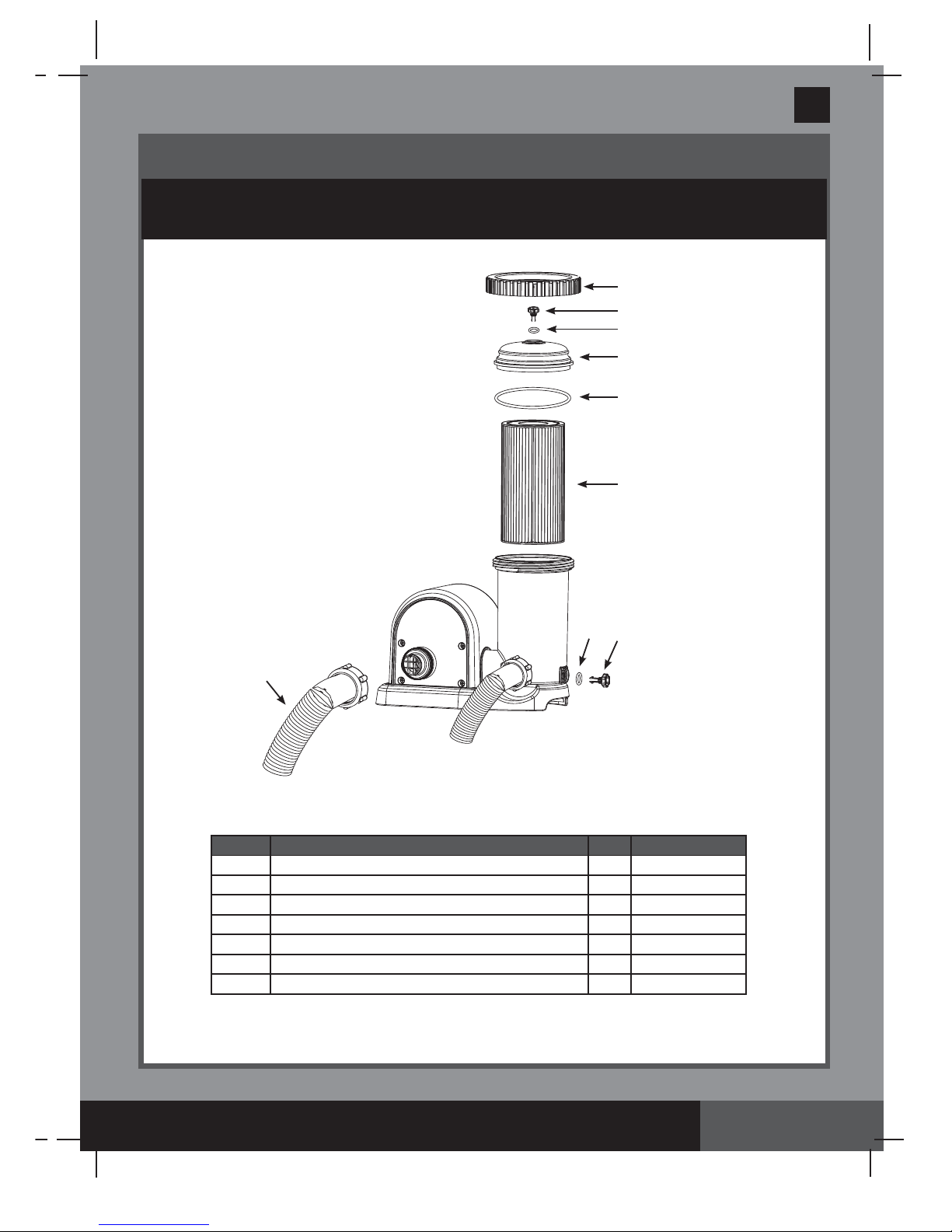
PARTS REFERENCE
Before assembling your product, please take a few minutes to check the contents
and become familiar with all the parts.
When ordering parts, be sure to quote the model number and part numbers.
1
2
3
4
5
6
7
REF. NO.
DESCRIPTION
QTY.
SPARE PART NO.
1
2
2
1
1
1
2
THREADED FILTER HOUSING COLLAR
AIR RELEASE VALVE/SEDIMENT RELEASE VALVE
VALVE O-RING
FILTER HOUSING COVER
FILTER HOUSING O-RING
FILTER CARTRIDGE (29900)
PUMP HOSE WITH NUTS
10749
10460
10264
10750
10325
11009 (FR: 11010)
2
3
4
5
1
6
3
7
2
NOTE:
Drawings for illustration purpose only. Actual product may vary. Not to scale.
Page 5
(108) MODEL 636T FILTER PUMP ENGLISH 7.5” X 10.3” PANTONE 295U 04/21/2014
108A
SAVE THESE INSTRUCTIONS
English
Page 5
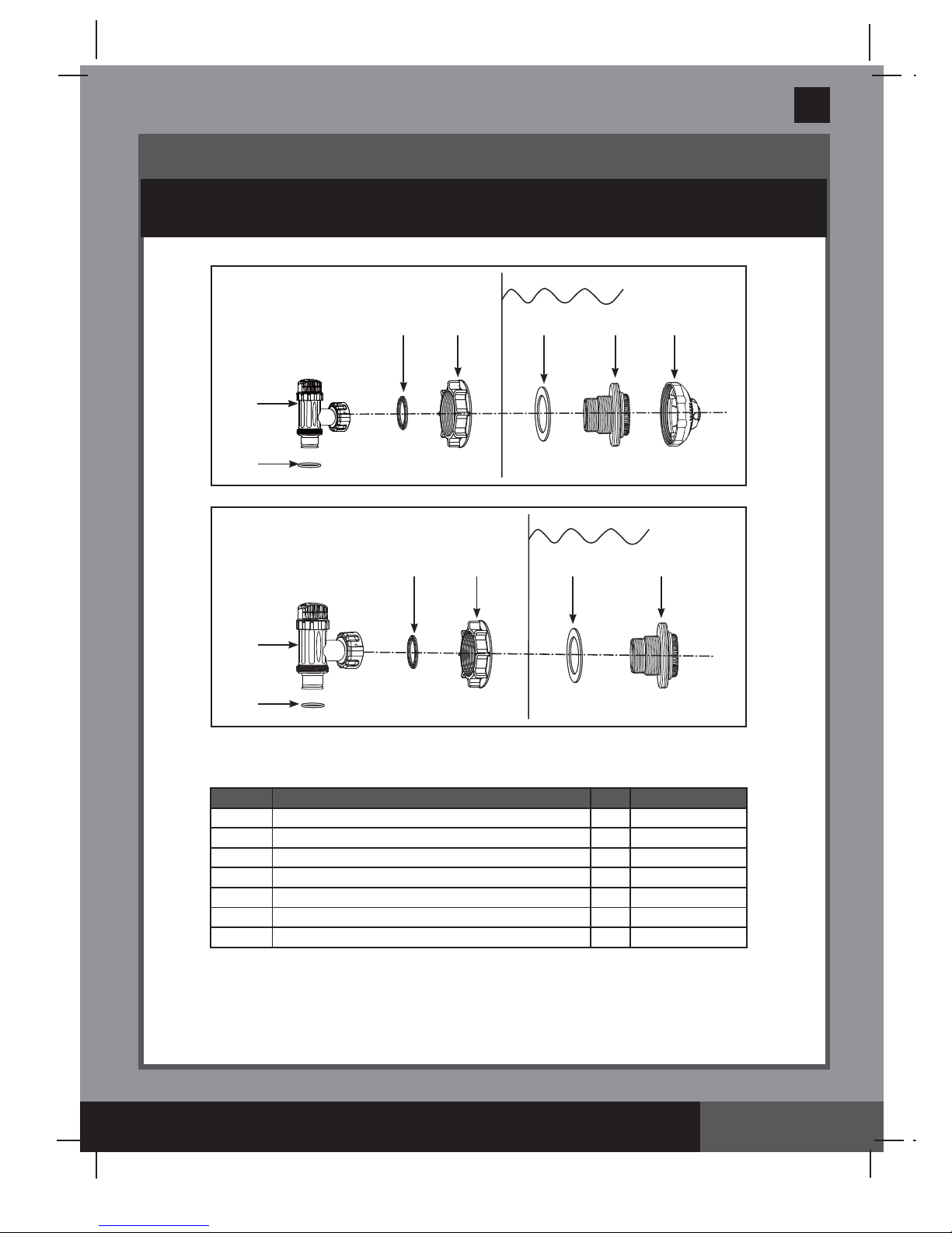
PARTS REFERENCE (continued)
Before assembling your product, please take a few minutes to check the contents
and become familiar with all the parts.
8*
9*
10*
11*
12*
13*
14*
REF. NO.
DESCRIPTION
QTY.
SPARE PART NO.
2
2
2
2
1
PLUNGER VALVE (HOSE O-RING & STEP WASHER INCLUDED)
HOSE O-RING
STEP WASHER
STRAINER NUT
FLAT STRAINER RUBBER WASHER
THREADED STRAINER CONNECTOR
ADJUSTABLE POOL INLET NOZZLE
10747
10262
10745
10256
10255
11235
11074
NOTE:
Drawings for illustration purpose only. Actual product may vary. Not to scale.
8
9
10 11 12 13 14
8
9
10 11 12 13
" * ":
Optional.
When ordering parts, be sure to quote the model number and part numbers.
*
*
Page 6

(108) MODEL 636T FILTER PUMP ENGLISH 7.5” X 10.3” PANTONE 295U 04/21/2014
108A
SAVE THESE INSTRUCTIONS
English
Page 6
1.
In a counter-clockwise motion unscrew
plunger valve union from the threaded
strainer connector
(13) (see drawing 1)
.
Be careful not to lose the step rubber
washer
(10)
. Place the plunger valve on
the ground in a safe place.
2.
In a counter-clockwise motion unscrew
the strainer nut
(11)
from the threaded
connector
(13)
. Leave the flat
washer
(12)
on the connector
(13)
.
3.
Install the strainer and plunger valve at the
lower position of pool outlet (marked "+").
From the inside of the pool liner insert
the connector
(13)
into one of the
pre-cut holes with the washer remaining
on the connector to be placed against
the inside of the liner wall.
4.
Before assembly, lubricate the threads
with a petroleum jelly. Then, with the flat
side of the strainer nut
(11)
facing the
outside wall of the liner in a clockwise
motion screw the strainer nut
(11)
back
onto the threaded connector
(13) (see
drawing 2)
.
5.
Finger tighten the strainer nut
(11)
onto
the threaded connector
(13)
.
6.
Grasp the plunger valve assembly. Make
sure the step washer
(10)
is in place.
7.
In a clockwise motion screw the plunger
valve union back onto the threaded
connector
(13) (see drawing 3)
.
8.
In a clockwise motion turn the plunger
valve handle to close position. Ensure the
plunger valve is securely closed. This will
prevent water from flowing out during
filling of the pool
(see drawing 4)
.
POOL OUTLET - STRAINER & PLUNGER VALVE SETUP (optional)
The strainer grid prevents large objects from jamming and/or damaging the filter pump.
The plunger valve assembly prevents water from flowing into the filter pump while the
filter cartridge is being placed or cleaned. If your pool has an inflatable top ring, install the
strainer, nozzle and plunger valve before inflating the pool liner top ring. The parts
numbers here onward, refer to the parts depicted in the Parts List section of this manual.
To install, do the following:
12 13
2
INSIDE
LINER WALL
11
1
2
1
3
1
2
4
INSIDE
LINER WALL
Page 7

(108) MODEL 636T FILTER PUMP ENGLISH 7.5” X 10.3” PANTONE 295U 04/21/2014
108A
SAVE THESE INSTRUCTIONS
English
Page 7
1.
In a counter-clockwise motion unscrew
plunger valve union from the threaded
strainer connector
(13) (see drawing 5)
.
Be careful not to lose the step rubber
washer
(10)
. Place the plunger valve on
the ground in a safe place.
2.
In a counter-clockwise motion unscrew
the strainer nut
(11)
from the threaded
connector
(13)
. Leave the flat
washer
(12)
on the connector
(13)
.
3.
Install the nozzle and plunger valve at the
upper position of the pool inlet. From the
inside of the pool liner insert the
connector
(13)
into one of the pre-cut
holes with the washer remaining on the
connector to be placed against the
inside of the liner wall.
4.
Before assembly, lubricate the threads
with a petroleum jelly. Then, with the flat
side of the strainer nut
(11)
facing the
outside wall of the liner in a clockwise
motion screw the strainer nut
(11)
back
onto the threaded connector
(13) (see
drawing 6)
.
5.
Finger tighten the adjustable pool inlet
nozzle
(14)
and the strainer nut
(11)
onto
the threaded connector
(13)
.
6.
Grasp the plunger valve assembly. Make
sure the step washer
(10)
is in place.
7.
In a clockwise motion screw the plunger
valve union back onto the threaded
connector
(13) (see drawing 7)
.
8.
In a clockwise motion turn the plunger
valve handle to close position. Ensure the
plunger valve is securely closed. This will
prevent water from flowing out during
filling of the pool
(see drawing 8)
.
9
. Adjust the direction of the nozzle head
pointing away from the pool outlet for a
better circulation result
(see drawing 9)
.
10.
The pool liner is now ready to be filled
with water. Consult the
above-ground-pool owner’s manual for
the filling instructions.
POOL INLET - NOZZLE & PLUNGER VALVE SETUP (optional)
5
1
7
1
2
6
12 13 14
INSIDE
LINER WALL
11
2
8
INSIDE
LINER WALL
9
Pool
WATER
FLOW
Page 8

(108) MODEL 636T FILTER PUMP ENGLISH 7.5” X 10.3” PANTONE 295U 04/21/2014
108A
SAVE THESE INSTRUCTIONS
English
Page 8
FILTER PUMP HOSE CONNECTION SETUP
1
. Remove the Krystal Clear™ filter pump and hoses from the packaging.
2
. Place the filter pump in such a manner, that you can easily assemble the hose
(7)
connections to the plunger valve.
Note: Some regional regulations may require the filter pump to be mounted on a
stationary platform. There are two mounting holes located in the pump base for this
reason. Consult your local authorities for filter-pump mounting requirements.
3
. Grasp the two pump hoses
(7)
and connect the hose nuts to the filter pump.
4
. In a counter-clockwise motion unscrew the threaded filter housing collar
(1)
from the filter
housing. Place it in a safe place.
5
. The filter pump is an airtight system. Turn the top air release valve
(2)
once or twice in a
counter-clockwise motion.
DO NOT remove the air release valve from the top cover, as
water will expel with force if the motor is turned on. This may cause injury.
6
. Grasp and remove the filter housing cover
(4)
. Check to see if a cartridge is inside the
housing. If yes, replace the cover, finger tighten the housing collar
(1)
back onto the filter
housing.
7
. Gently finger tighten the sediment release valve located at the bottom of the housing to be
sure that water does not leak out.
8
. When the pool is filled connect the hose from the bottom of the filter housing to the highest
strainer assembly. You will find the hose connection at the bottom of the plunger valve
assembly. Use the hose nut to attach the hose.
9
. Connect the second hose which is fixed to the middle of the motor housing to the
remaining liner connection.
WARNING
Position this product away from the pool, so as to prevent children from
climbing on it and accessing the pool.
The installation instruction shall provide information on requirements specified for the electrical
installation and shall include reference to national wiring rules.
THREADED FILTER
HOUSING COLLAR
HOSE NUT
OUTLET HOSE
WATER LEVEL
ADJUSTABLE POOL
INLET NOZZLE
INSIDE LINER
WALL
THREADED
STRAINER
CONNECTOR
OUTSIDE LINER
WALL
(ILLUSTRATION NOT TO SCALE)
INLET HOSE
W
A
T
E
R
F
L
O
W
W
A
T
E
R
F
L
O
W
PLUNGER VALVE
ASSEMBLY
FILTER CARTRIDGE
INSIDE
MOTOR
HOUSING
AIR RELEASE
VALVE
FILTER HOUSING
COVER
HOSE O-RING
POWER CORD
HOSE
O-RING
Page 9

(108) MODEL 636T FILTER PUMP ENGLISH 7.5” X 10.3” PANTONE 295U 04/21/2014
108A
SAVE THESE INSTRUCTIONS
English
Page 9
FILTER PUMP STATIONARY MOUNTING OPTION
Some countries, especially in the European community, require the filter-pump to be secured to the
ground or to a base in a permanent upright position. Check your local authorities to determine if there
is a regulation in your area regarding above-the-ground swimming pool filter-pumps. If yes, then the
filter-pump can be mounted to a platform using the two holes located in the base. See drawing below.
The filter-pump can be mounted on a cement base or onto a wooden platform to prevent accidental
falling over. Total assembly must exceed 18kg.
130 mm
1
. The mounting holes are 6.4mm in diameter and spaced 130mm apart.
2
. Use two bolts and lock nuts with a maximum of 6.4mm in diameter.
Page 10

(108) MODEL 636T FILTER PUMP ENGLISH 7.5” X 10.3” PANTONE 295U 04/21/2014
108A
SAVE THESE INSTRUCTIONS
English
Page 10
1.
Make sure the filter pump is switched off. The switch is located on the motor housing.
2.
Connect the power cord to a GFCI protected electrical outlet.
3.
Turn both plunger valve handles fully counter-clockwise until they stop. This opens the
valve, allowing water to flow into the filter pump.
4
. With water flowing into filter pump, the water pressure will allow the air trapped inside to
escape from the air release valve
(2).
When all the air has escaped water will flow out of the
valve
(2).
When this occurs gently finger tighten the valve
(2)
in a clockwise direction.
5. To operate the filter pump on “TIMER” mode:
A. Set the timer dial to the desired operating hours. See operation time table. See Fig. 10
B. Turn on the pump by pressing the switch to “ ” position, the filter pump is now filtering
the water and will stop after the operating hours are completed. The built-in timer will
now operate for the number of hours selected at the same time each day.
C. Operating hours can be re-adjusted if necessary. Follow step A – B.
To operate the filter pump manually (without the “TIMER” mode):
A. Turn on the pump by pressing the switch to “-” position, the filter pump is now filtering
the water.
B. To turn off the pump, press the switch to “O” position.
To prevent air lock, open the lower plunger valve (connected inlet hose) first and
then the upper plunger valve (connected outlet hose). Open the air release valve,
wait until water starts to flow out of the air release valve, close air release valve.
IMPORTANT
OPERATING INSTRUCTIONS
Risk of electric shock. Connect this product only to a grounding type
receptacle protected by a ground-fault circuit interrupter (GFCI) or
residual current device (RCD). Contact a qualified electrician if you
cannot verify that the receptacle is protected by a GFCI/RCD. Use a
qualified electrician to install the GFCI/RCD, which has a maximum rate
of 30mA. Do not use a portable residual current device (PRCD).
WARNING
2
4
6
8
12
ON
OFF
TIMER
FIG 10
TIMER DIAL (HOURS)
6.
Never put pool chemicals directly into the filter pump. This may damage the pump and void
the warranty.
Page 11

(108) MODEL 636T FILTER PUMP ENGLISH 7.5” X 10.3” PANTONE 295U 04/21/2014
108A
SAVE THESE INSTRUCTIONS
English
Page 11
OPERATING TIME TABLE
This table shows the required operating time for average use of the filter pump with AGP's.
The filter pump running time should be 1 hour longer than the required operating time of the
Saltwater System.
Pool Size
Water Capacity (Calculated at 90%
for Frame Pool and 80% for Easy Set
& Oval Pool)
Recommend
operating hours
per day
(Gals)
(Liters) (Hours)
INTEX ABOVE GROUND POOLS (AGP’s)
EASY SET®
POOL
18’ x 42” (549cm x 107cm)
4,786 18,115 4
18’ x 48” (549cm x 122cm)
5,455 20,647 6
CIRCULAR
METAL FRAME
POOL
18’ x 48” (549cm x 122cm)
6,423 24,311 6
21’ x 52”
9,533 36,082 8
ULTRA FRAME
POOL
16' x 48" (488cm x 122cm)
5,061 19,156 4
18’ x 48” (549cm x 122cm)
6,423 24,311 6
18’ x 52” (549cm x 132cm)
6,981 26,423 6
20’ x 48”
7,947 30,079 6
SEQUOIA SPIRIT®
POOL SET
15’8” x 49”
4,440 16,805 4
16'8" x 49" (508cm x 124cm)
5,061 19,156 4
18'8" x 53" (569cm x 135cm)
6,981 26,423 6
OVAL FRAME
POOL
20’ x 12’ x 48” (610cm x 366cm x 122cm)
4,393 16,628 4
RECT. ULTRA
FRAME POOL
15’ x 9’ x 48”
3,484 13,187 4
18’ x 9’ x 52” (549cm x 274cm x 132cm)
4,545 17,203 4
20’ x 10’ x 52”
5,611 21,238 4
24’ x 12’ x 52” (732cm x 366cm x 132cm)
8,403 31,805 6
Page 12

(108) MODEL 636T FILTER PUMP ENGLISH 7.5” X 10.3” PANTONE 295U 04/21/2014
108A
SAVE THESE INSTRUCTIONS
English
Page 12
CLEANING OR REPLACING FILTER CARTRIDGES
It is recommended that the filter cartridge be replaced at least every 2
weeks.
1
. Make sure the filter pump is turned off, then disconnect the power cord from the electrical
outlet.
2
. Turn both plunger valve handles fully clockwise until they stop. This closes the valve, prevents
the water from flowing out of the pool.
3
. Gently turn the top air release valve once or twice in a counter-clockwise direction. The
housing cover can now be easily removed.
4
. In a counter-clockwise direction remove the filter housing collar
(1).
Place it in a safe location.
5
. Remove the housing cover
(4).
6
. Now remove the used filter cartridge.
7
. Examine the inside of the filter housing.
8
. If dirt or sediment is located on the bottom of the housing then:
A
. In a counter-clockwise motion gently unscrew and remove the sediment valve
(2)
located
at the bottom of the housing. Place it in a safe place.
B
. With a bucket of water or a garden hose pour water into the housing flushing out the
sediment.
C
. Screw back the sediment valve
(2)
in a gentle clockwise motion. Do not over-tighten.
9
. Place a new cartridge filter in the housing.
10
. Return the housing cover
(4)
to its position and in a clockwise direction rescrew the housing
collar
(1)
onto the filter housing.
11.
Turn both plunger valve handles fully counter-clockwise until they stop. This opens the valve,
allowing water to flow into the filter pump.
12
. When the trapped air has escaped through the air release valve gently retighten the valve
(2)
in a clockwise direction.
13
. Reconnect the power cord.
14
. Turn on the pump.
Page 13

(108) MODEL 636T FILTER PUMP ENGLISH 7.5” X 10.3” PANTONE 295U 04/21/2014
108A
SAVE THESE INSTRUCTIONS
English
Page 13
POOL CARE AND CHEMICALS
• All pools require care to keep the water clear and hygienically clean. With proper chemical
control, your filter will help attain this objective. Consult your pool supply dealer for instructions
regarding the proper use of chlorine, algaecide and other chemical agents required for
sparkling clear water.
• Keep pool chemicals away from children.
• Do not replenish chemicals in pool while pool is occupied. Skin or eye irritations could occur.
• Daily pH checking and chemical treatment of the water is very important and can not be
overemphasized. Chlorine, algaecide and maintenance of proper pH levels are required when
filling the pool as well as during the season. Consult your local swimming pool supply store for
instructions.
• The season's first filling of the pool may have brackish water requiring extra water additives and
extra filter changes. Do not allow swimming in pool until the pH level is balanced. Consult your
local swimming pool supply store for instructions.
• Keep spare filter cartridges on hand. Replace cartridges every two weeks.
• Chlorinated water may damage lawns, gardens or shrubbery as children play in the pool and
splash water outside the pool. Lawn areas underneath the pool liner will be destroyed. Note
that some types of grass may grow through the liner.
• Filter run time depends on pool size, weather and usage level. Experiment with various run
times so as to produce clean clear water.
CAUTION
Concentrated chlorine solutions may damage the pool liner. Always follow
the chemical manufacturer’s directions, and the health and hazard warnings.
1
. Before emptying your pool for long term storage, or relocation, be sure the water is directed
towards an acceptable drain water receptacle away from the house. Check local regulations for
specific directions regarding disposal of swimming pool water.
2
. Disconnect power cord from electrical outlet.
3
. Now, drain the pool.
4
. When the pool is empty, disconnect all hoses from pump and plunger valves and remove the
strainers from the pool wall.
5
. Drain all water from the filter pump.
6
. Leave filter pump pieces & hoses outside to thoroughly air dry.
7
. Remove both plunger valves from the threaded strainer connector
(13)
. Be careful not to lose
the step rubber washer
(10)
.
8
. Coat the following O-rings and washers with petroleum jelly for long term storage:
• Air release valve & sediment O-rings
(3)
.
• Filter housing cover O-ring
(5)
.
• Pump hose O-rings
(9)
.
• Strainer valve assembly step washers
(10)
.
• Flat strainer rubber washers
(12)
.
9
. Discard the used filter cartridge. Put aside 1 or 2 new cartridges for next season’s use.
10
. It is best to place all dry pieces in the original packaging for storage or place them in an airtight
plastic bag.
11
. Store the unit and accessories in a dry place. The storage's temperature should be controlled,
between 32 degrees Fahrenheit (0 degrees Celsius) and 104 degrees Fahrenheit (40 degrees
Celsius) storage location.
LONG TERM STORAGE
IMPORTANT
It is best to store away your poolsystem in its original packaging.
Page 14

(108) MODEL 636T FILTER PUMP ENGLISH 7.5” X 10.3” PANTONE 295U 04/21/2014
108A
SAVE THESE INSTRUCTIONS
English
Page 14
TROUBLESHOOTING GUIDE
IMPORTANT
If you continue to experience difficulty, please contact our Consumer Service Department for
assistance. See separate “Authorized Service Centers” sheet.
FILTER MOTOR
FAILS TO START
FILTER DOESN’T
CLEAN POOL
FILTER DOESN’T PUMP
WATER OR THE WATER
FLOW IS VERY SLOW
PUMP DOESN’T WORK
TOP COVER
LEAKING
HOSE LEAKING
AIR LOCK
• The motor is not plugged in.
• The GFCI/RCD circuit breaker
is tripped.
• Motor too hot and overload
protection is shut off.
• Improper chlorine or pH
levels.
• Filter cartridge is dirty.
• Damaged cartridge.
• Excessively dirty pool.
• The strainer screen is
restricting the water flow.
• Clogged inlet or discharge.
• An air leak on the intake line.
• Scale or buildup on cartridge.
• Excessively dirty pool.
• Dirty filter cartridge.
• The nozzle and strainer
connection are reversed.
• Low water level.
• Strainer screen plugged up.
• An air leak on the intake hose.
• Faulty motor or the impeller is jammed.
• An air lock inside the cartridge
chamber.
• O-ring missing.
• Cover or air release valve are not tight.
• Hose nuts are not well-fitted.
• Hose o-ring dislodged when
connecting the hose.
• Hose broken.
• There’s air trapped in the
pump housing and inlet hose.
• The inlet and outlet hoses
connection are reversed.
TROUBLE CAUSE SOLUTION
•
Filter cord must be plugged into a 3 wire
outlet that is protected by a Class A
Ground Fault Circuit Interrupter, or RCD.
• Reset circuit breaker. If circuit breaker
trips repeatedly, your electrical system
may have a defect. Turn off circuit
breaker and call an electrician to
correct the problem.
• Let the motor cool down.
• Adjust the chlorine and pH level. Consult
your local swimming pool supply stores.
• Clean or replace cartridge.
• Check the cartridge for holes. Replace
if damaged.
• Operate the filter for longer periods.
• Clean the strainer screen at the inlet.
• Clear any obstructions in the intake hose by
discharging it inside pool wall.
• Tighten hose nuts, check hoses for
damage, check pool water level.
• Replace cartridge.
• Clean cartridge more often.
• Clean inside the plunger valve.
• Pull valve handle to full upright position.
• Install the nozzle at the upper position of
the pool inlet, and the strainer at the lower
position of the pool outlet.
• Fill pool to correct water level.
• Clean strainer screens at pool inlet.
• Tighten hose nuts, check hose for damage.
• Clear any sticks or leaves in the intake hose.
• Turn and pull valve handle to full
upright position.
• Remove cover & check for O-ring.
• Tighten cover or valve (Manually).
• Tighten or reinstall hose nut.
• Put the o-ring back into the groove.
• Replace a new hose.
• Open air release valve, wait until water
starts to flow out of the valve, then close it.
• The lower position of pool outlet
connects to filter pump water inlet. The
upper position of pool inlet connects to
filter pump water outlet.
Page 15

(108) MODEL 636T FILTER PUMP ENGLISH 7.5” X 10.3” PANTONE 295U 04/21/2014
108A
SAVE THESE INSTRUCTIONS
English
Page 15
COMMON POOL PROBLEMS
PROBLEM DESCRIPTION CAUSE SOLUTION
ALGAE
COLORED
WATER
FLOATING
MATTER IN
WATER
CHRONIC LOW
WATER LEVEL
SEDIMENT ON
POOL BOTTOM
SURFACE DEBRIS
• Chlorine and pH levels
need adjustment.
• Copper, iron or manganese in
water being oxidized by the
added chlorine.
This is Common.
• "Hard water" caused by a too
high pH level.
• Chlorine content is low.
• Foreign matter in water.
• Rip or hole in pool liner or hoses.
• The drain valves are loose.
• Heavy use, getting in
and out of pool.
• Pool too close to trees.
• Super chlorinate with shock
treatment. Correct pH to your pool
store's recommended level.
• Vacuum pool bottom.
• Maintain proper chlorine level.
• Adjust pH level to the
recommended level.
• Run filter until water is clear.
• Clean cartridge frequently.
• Correct the pH level. Check with your
pool dealer for advice.
• Adjust the chlorine level.
• Clean or replace your filter.
• Repair with a patch kit.
• Finger tighten all caps.
• Use Intex pool vacuum to clean
bottom of pool.
• Use Intex pool skimmer.
• Greenish water.
• Green or black spots on
pool liner.
• Pool liner is slippery and/
or has a bad odor.
• Water turns blue,
brown, or black
when first treated
with chlorine.
• Water is cloudy or
milky.
• Level is lower than
on previous day.
• Dirt or sand on
pool floor.
• Leaves, insects etc.
GENERAL AQUATIC SAFETY
Water recreation is both fun and therapeutic. However, it involves inherent risks of
injury and death. To reduce your risk of injury, read and follow all product, package and
package insert warnings and instructions. Remember, however, that product warnings,
instructions and safety guidelines cover some common risks of water recreation, but do
not cover all risks and or dangers.
For additional safeguards, also familiarize yourself with the following general guidelines
as well as guidelines provided by nationally recognized Safety Organizations:
• Demand constant supervision. A competent adult should be appointed as a “lifeguard” or
water watcher, especially when children are in and around the pool.
• Learn to swim.
• Take the time to learn CPR and first aid.
• Instruct anyone who is supervising pool users about potential pool hazards and about the
use of protective devices such as locked doors, barriers, etc.
• Instruct all pool users, including children what to do in case of an emergency.
• Always use common sense and good judgement when enjoying any water activity.
• Supervise, supervise, supervise.
Page 16

(108) MODEL 636T FILTER PUMP ENGLISH 7.5” X 10.3” PANTONE 295U 04/21/2014
108A
SAVE THESE INSTRUCTIONS
English
Page 16
Your Krystal Clear™ Filter-Pump has been manufactured using the highest quality
materials and workmanship. All Intex products have been inspected and found free of
defects prior to leaving the factory. This Limited Warranty applies only to the Krystal
Clear™ Filter-Pump and accessories listed below.
The following provision is only valid within the European member states countries: The
legal regulation of Directive 1999/44/EC will not be effected by this Intex warranty.
The provisions of this Limited Warranty apply only to the original purchaser and is not
transferable. This Limited Warranty is valid for the period noted below from the date of the
initial retail purchase. Keep your original sales receipt with this manual, as proof of
purchase will be required and must accompany warranty claims or the Limited Warranty is
invalid.
Krystal Clear™ Filter-Pump Warranty – 1 Year
Hoses, Plunger Valves & Fittings Warranty – 180 days
If a manufacturing defect is found within the periods noted above, please contact the
appropriate Intex Service Center listed in the separate “Authorized Service Centers” sheet.
The Service Center will determine the validity of the claim.
IMPLIED WARRANTIES ARE LIMITED TO THE TERMS OF THIS WARRANTY AND IN
NO EVENT SHALL INTEX, THEIR AUTHORIZED AGENTS OR EMPLOYEES BE LIABLE
TO THE BUYER OR ANY OTHER PARTY FOR DIRECT OR CONSEQUENTIAL
DAMAGES OR LIABILITIES.
This Limited Warranty does not apply if the products are subject to negligence, abnormal
use or operation, accident, improper operation, improper voltage or current contrary to
operating instructions, or to damage by circumstances beyond Intex’s control, including but
not limited to, ordinary wear and tear and damage caused by exposure to fire, flood,
freezing, rain, or other external environmental forces. This Limited Warranty applies only to
those parts and components sold by Intex. The Limited Warranty does not cover
unauthorized alterations, repairs or disassembly by anyone other than Intex Service
Center personnel.
The Limited Warranty is also not applicable if this product is used with another product
other than an Intex product, when setting up your pool.
The costs associated with the loss of pool water, chemicals or water damage are not
covered by this warranty. Injury or damage to any property or person is not covered by this
warranty.
LIMITED WARRANTY
 Loading...