

Page 1
112
(112) MODEL 6220 KRYSTAL CLEAN POOLWATER SYSTEM ENGLISH 7.5” X 10.5” PANTONE 295U 12/25/2006
OOWWNNEERR’’SS MMAANNUUAALL
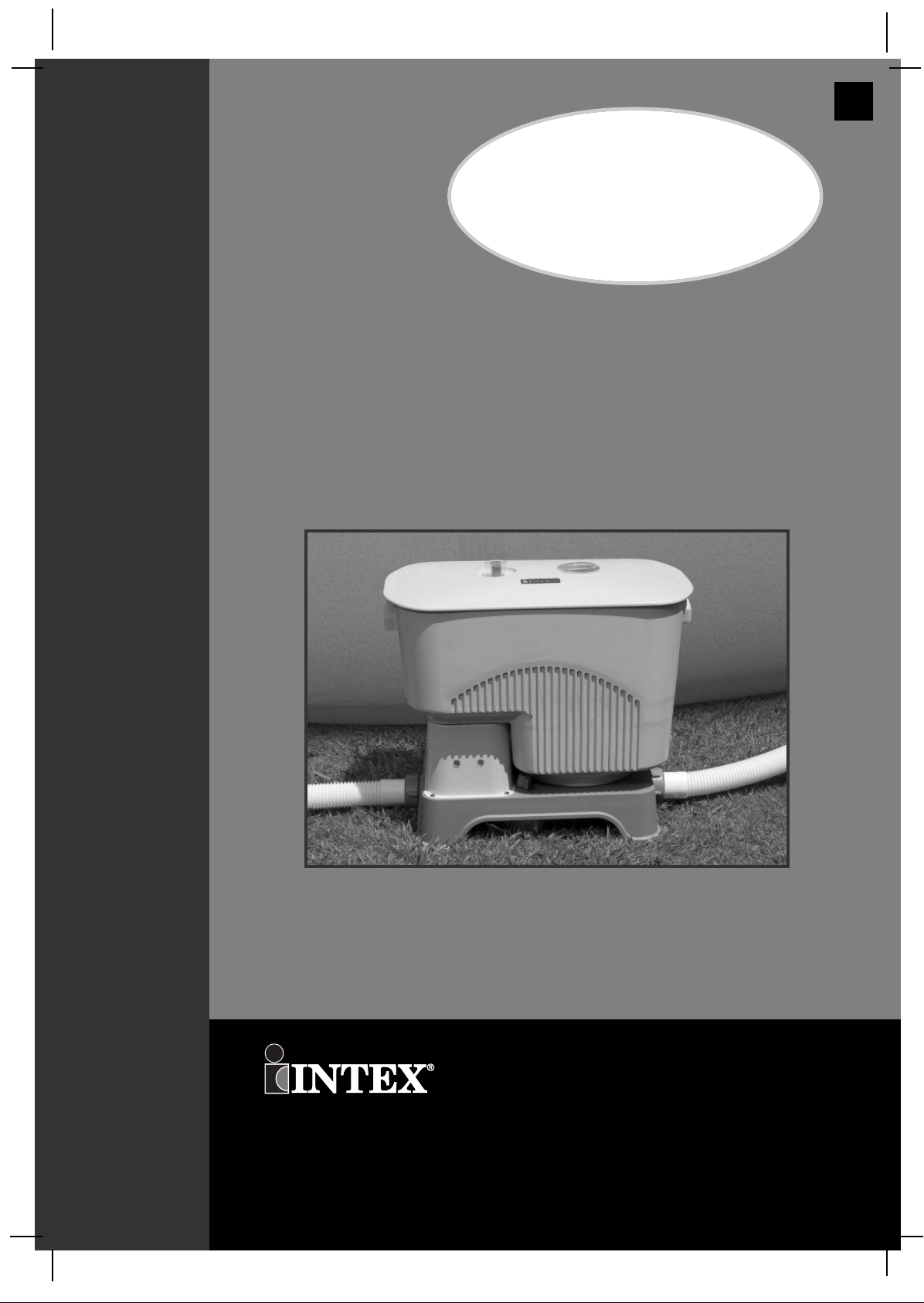
Krystal Clean Poolwater™
System
Model 6220
220 - 240 V~, 50 Hz,
160 W, IPX5
IMPORTANT
SAFETY RULES
Read, Understand, and Follow all
Instructions Carefully before
Installing and using this Product.
Don’t forget to try these other fine Intex products: Pools, Pool Accessories,
Inflatable Pools and In-Home Toys, Airbeds and Boats available at fine
retailers or visit our website.
112**-A1-0712
For illustrative purposes only.
©2006 Intex Marketing Ltd. - Intex Development Co. Ltd. - Intex Recreation Corp.
All rights reserved/Tous droits réservés/Todos los derechos reservados/Alle
Rechte vorbehalten.
Printed in China/Imprimé en Chine/Impreso en China/Gedruckt in China.
®™ Trademarks used in some countries of the world under license from/®™ Marques utilisées dans certains pays sous
licence de/Marcas registradas utilizadas en algunos países del mundo bajo licencia de/Warenzeichen verwendet in einigen
Ländern der Welt in Lizenz von/Intex Marketing Ltd. to/à/a/an Intex Development Co. Ltd., 8th Floor, Dah Sing
Financial Centre, 108 Gloucester Road, Wanchai, Hong Kong & Intex Recreation Corp., P.O. Box 1440, Long Beach,
CA 90801 • Distributed in the European Union by/Distribué dans l’Union Européenne par/Distribuido en la unión Europea
por/Vertrieb in der Europäischen Union durch/Intex Trading B.V., P.O. Box nr. 1075 – 4700 BB Roosendaal – The
Netherlands
Page 2
112
SAVE THESE INSTRUCTIONS
Page 2
(112) MODEL 6220 KRYSTAL CLEAN POOLWATER SYSTEM ENGLISH 7.5” X 10.5” PANTONE 295U 12/25/2006
TTAABBLLEE OOFF CCOONNTTEENNTTSS
Warnings.............................................................................. 3
Parts List & Reference........................................................ 4-6
Product Information & Specifications............................... 7
Set Up Instructions............................................................. 8-10
Stationary Mounting Option............................................... 11
Salt and Pool Water Volumes............................................. 12-13
Operating Instructions........................................................ 14-18
Intex Pools Operating Time Table...................................... 15-16
Non-Intex Pools Operating Time Table.............................. 16
Alarms.................................................................................. 19-21
Maintenance......................................................................... 22-24
Long Term Storage.............................................................. 23
INTEX 3-Way Test Strips..................................................... 23
Pool Maintenance and Chemical Definitions.................... 24
Troubleshooting Guide....................................................... 25
General Aquatic Safety....................................................... 26
Limited Warranty................................................................. 27
Intex Service Center Locations.......................................... 28
Page 3
112
SAVE THESE INSTRUCTIONS
Page 3
(112) MODEL 6220 KRYSTAL CLEAN POOLWATER SYSTEM ENGLISH 7.5” X 10.5” PANTONE 295U 12/25/2006
SSAAFFEETTYY RRUULLEESS
WARNING
• To reduce the risk of injury, do not permit children to use this product. Always
supervise children and those with disabilities.
• Risk of electric shock. Connect this product only to a grounding type receptacle
protected by a ground-fault circuit interrupter (GFCI) or residual current device
(RCD). Contact a qualified electrician if you cannot verify that the receptacle is
protected by a GFCI/RCD. Use a qualified electrician to install the GFCI/RCD,
which has a maximum rate of 30mA. Do not use a portable residual current device
(PRCD).
• Do not bury electrical cord. Locate cord where it will not be damaged by lawn
mowers, hedge trimmers, and other equipment.
• If the supply cord is damaged, it must be replaced by the manufacturer, its service
agent or similarly qualified persons in order to avoid a hazard.
• To reduce the risk of electric shock, do not use extension cords, timers, plug
adaptors or converter plugs to connect unit to electric supply; provide a properly
located outlet.
• Assembly and disassembly by adults only.
• Do not attempt to plug in or unplug this product while standing in water or when
your hands are wet.
• Position this product away from pool to prevent a child from climbing on pump to
access the pool.
• Children must stay away from this product and electrical cord(s).
• Do not operate this product when pool is occupied.
• Never use the pool if indicated chlorine level is more than 3ppm.
• Always unplug this product from the electrical outlet before removing, cleaning,
servicing or making any adjustment to the product.
• This product is intended to be used only for the purposes described in the manual!
• Operating this product without water flowing through the system can cause a build
up of flammable gases which can result in FIRE OR EXPLOSION.
• This product is for use with storable pools only. Do not use with
permanently-installed pools. A storable pool is constructed so that it is capable of
being readily disassembled for storage and reassembled to its original integrity.
• Keep this product more than 2m away from the pool (For France only).
• Keep the plug of this product more than 3.5m away from the pool.
• The plug shall be accessible after product installed.
FAILURE TO FOLLOW THESE WARNINGS MAY RESULT IN
PROPERTY DAMAGE, ELECTRIC SHOCK, ENTANGLEMENT OR
OTHER SERIOUS INJURY OR DEATH.
These product warnings, instructions and safety rules provided with the product represent
some common risks of water recreation devices and do not cover all instances of risk and
danger. Please use common sense and good judgement when enjoying any water activity.
IMPORTANT SAFETY RULES
Read, Understand and Follow All Instructions Carefully Before Installing and Using this Product.
READ AND FOLLOW ALL INSTRUCTIONS
Page 4
112
SAVE THESE INSTRUCTIONS
Page 4
(112) MODEL 6220 KRYSTAL CLEAN POOLWATER SYSTEM ENGLISH 7.5” X 10.5” PANTONE 295U 12/25/2006
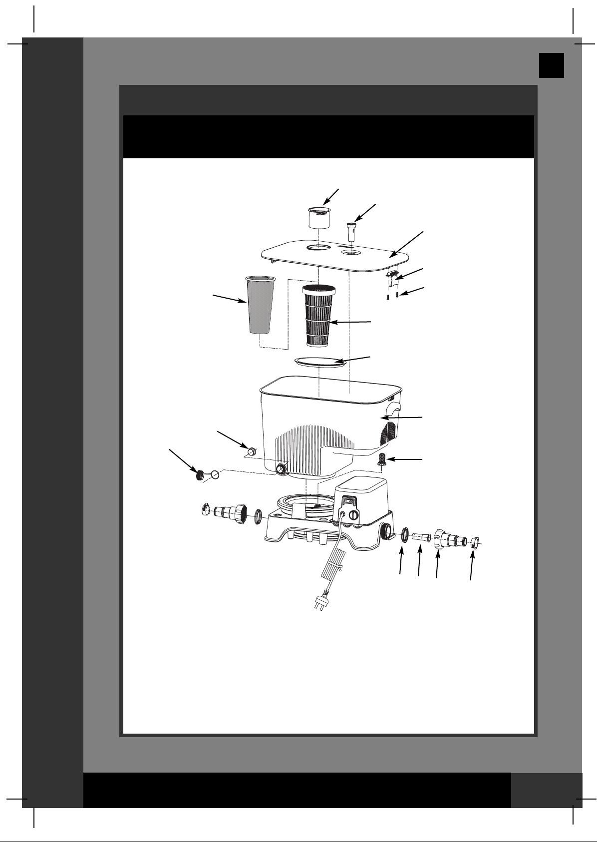
PPAARRTTSS LLIISSTT
PARTS LIST
NOTE: Drawings for illustration purpose only. May not reflect actual product. Not to scale.
123
654
78 9
10 11 12
13 14 15
16 17 18
19
* Optional
* Optional
* Optional
* Optional
* Optional
Page 5
112
SAVE THESE INSTRUCTIONS
Page 5
(112) MODEL 6220 KRYSTAL CLEAN POOLWATER SYSTEM ENGLISH 7.5” X 10.5” PANTONE 295U 12/25/2006
PPAARRTTSS RREEFFEERREENNCCEE
PARTS REFERENCE
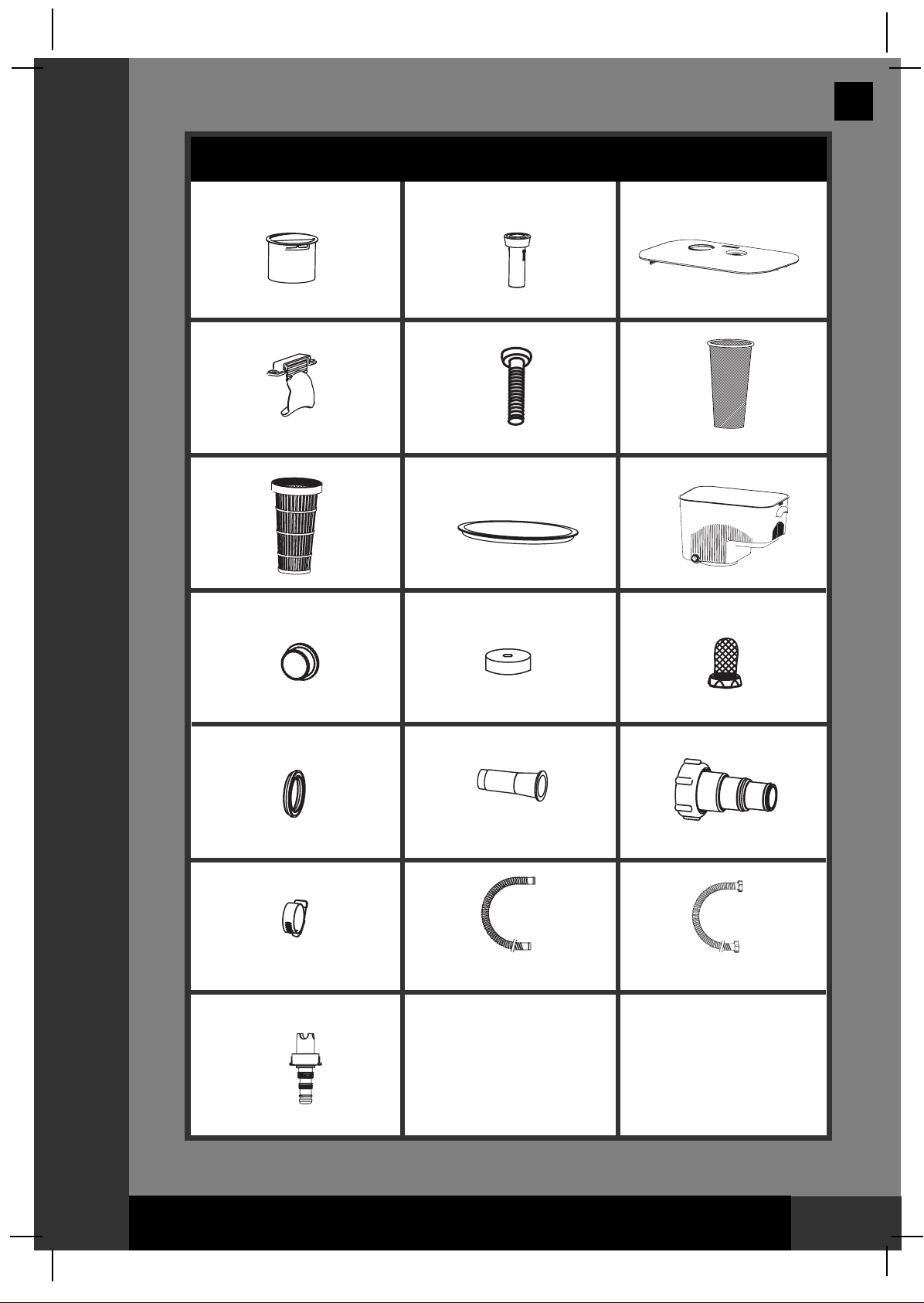
Before assembling your product, please take a few minutes to check the contents
and become familiar with all the parts.
3
4
5
1
2
6
8
9
12
10
11
13
14
15
16
7
NOTE: Drawings for illustration purpose only. May not reflect actual product. Not to
scale.
Page 6
112
SAVE THESE INSTRUCTIONS
Page 6
(112) MODEL 6220 KRYSTAL CLEAN POOLWATER SYSTEM ENGLISH 7.5” X 10.5” PANTONE 295U 12/25/2006
PPAARRTTSS RREEFFEERREENNCCEE
PARTS REFERENCE (continued)
Before assembling your product, please take a few minutes to check the contents
and become familiar with all the parts.
1
2
3
4
5
6
7
8
9
10
11
12
13
19
14
15
16
17
18
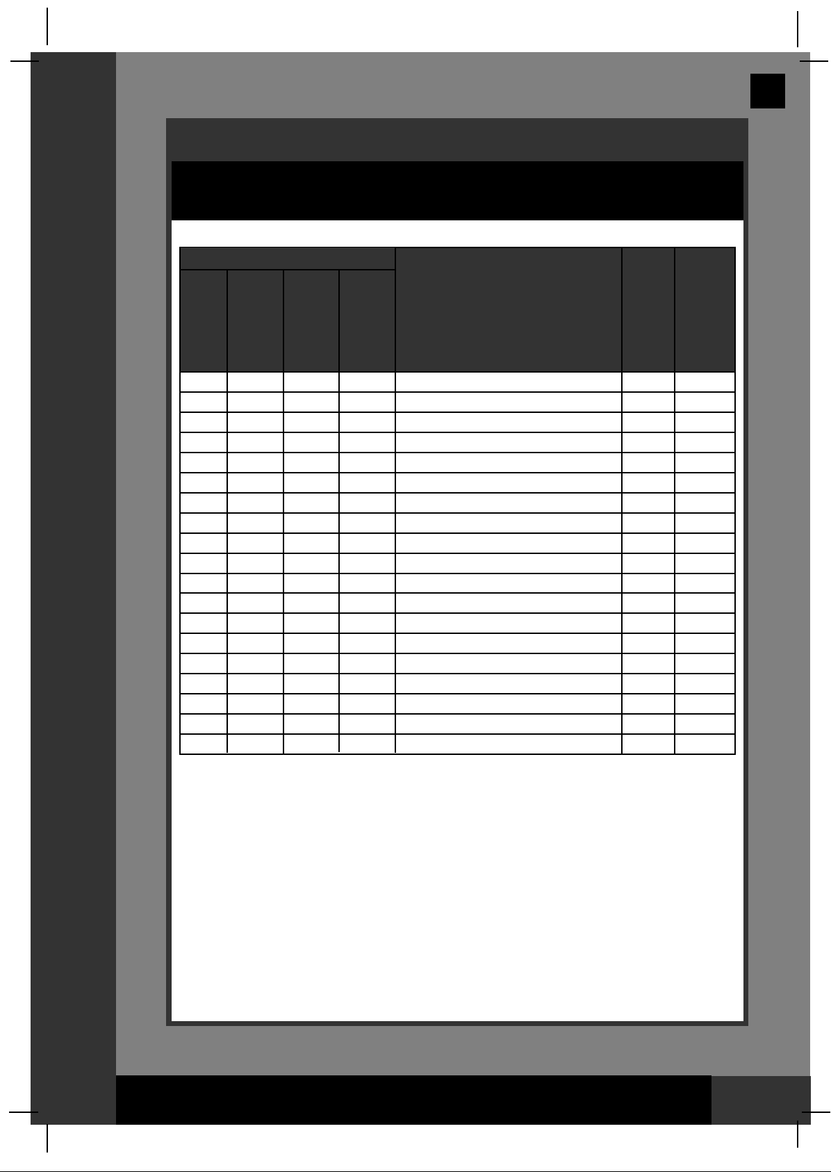
REF. NO.
DESCRIPTION
QTY.
SPARE
PART
NO.
1
1
1
2
4
1
1
1
1
1
1
1
2
1
2
2
1
1
1
SALT MEASURING SCOOP
WATER LEVEL INDICATOR
TANK COVER (COVER CLIPS & SCREWS INCLUDED)
COVER CLIP
SCREW
SALT CONTAINER NET
SALT CONTAINER
SALTWATER TANK FILTER
SALTWATER TANK
DRAIN VALVE PLUG
DRAIN VALVE CAP
WATER FILTER
O-RING
WATER BAFFLE ADAPTOR A (OPTIONAL)
ADAPTOR A WITH THREADED COLLAR (OPTIONAL)
HOSE CLAMP (OPTIONAL)
HOSE (OPTIONAL)
CONNECTOR HOSE WITH THREADED FITTINGS (OPTIONAL)
DRAIN CONNECTOR
10999
11045
11000
11046
11047
11048
11001
11049
11002
10044
10649
11003
11050
11051
10849
10122
10116
10720
10201
COMMON
FOR
CONNECTION
TO ABOVE
GROUND
POOLS
EQUAL OR
HIGHER THAN
42" (107 CM)
IN HEIGHT
FOR
CONNECTION
TO FILTER
PUMPS WITH
1-1/4" (32MM)
HOSE SIZE
FOR
CONNECTION
TO FILTER
PUMPS WITH
1-1/2" (38MM)
HOSE SIZE
Page 7
112
SAVE THESE INSTRUCTIONS
Page 7
(112) MODEL 6220 KRYSTAL CLEAN POOLWATER SYSTEM ENGLISH 7.5” X 10.5” PANTONE 295U 12/25/2006
PPRROODDUUCCTT IINNFFOORRMMAATTIIOONN//SSPPEECCSS
Common salt (sodium chloride) is made up of two elements, sodium
and chlorine. During the installation of your Saltwater System, a
measured quantity of salt is dissolved in the saltwater tank with pool
water to make it slightly salty. This salty water is passed through the
saltwater system’s electrolytic cell to produce HOCL which dissolves
instantly in the water. The HOCL destroys bacteria, viruses, algae and
oxidizes other organic materials.
Key Saltwater System Parts:
• Power Supply
The power supply converts AC electrical current to a low voltage DC
current. This is required by the electrolytic cell to perform the electrolysis
that creates chlorine.
• Electrolytic Cell (with Titanium Plates)
The electrolytic cell contains bipolar titanium electrodes which perform the
electrolysis and produce liquid sanitizer (HOCL) when energized with DC
electricity. Sanitizer is generated when pool water containing salt passes
through the cell. The sanitizer production can be varied by changing the
number of hours the saltwater system is operating each day. The
saltwater system has a built-in self cleaning cycle that operates every
ten hours without interrupting sanitizer production.
• Flow Sensor
The flow sensor protects the electrolytic cell and ensures there is
adequate water flowing through the cell. When the water flow drops below
a minimum flow rate, the electrolytic cell will automatically shut down to
protect the titanium plates. A safety buzzer will sound and the red LED on
the right will light up indicating the problem.
• Electronic Control Station
The electronic control station contains two LED lights and a time control
dial to program the saltwater system operating hours. It also monitors
the different parameters such as salt concentration, water flow and the
electrolytic cell activity. If any deviation from the norm occurs then a
buzzer will sound and the red LED on the right will light up indicating the
problem.
PRODUCT SPECIFICATIONS
Power: 220 - 240 Volt
Wattage: 160 W
Maximum Sanitizer Output/hour: 18 grams/hour
Minimum Flow Rate: 500 gallons/hour (1893 liters/hour)
Limited Warranty: 1 Year (see “Limited Warranty”)
HOW SANITIZER IS GENERATED
Page 8
112
SAVE THESE INSTRUCTIONS
Page 8
(112) MODEL 6220 KRYSTAL CLEAN POOLWATER SYSTEM ENGLISH 7.5” X 10.5” PANTONE 295U 12/25/2006
SSEETT--UUPP IINNSSTTRRUUCCTTIIOONNSS
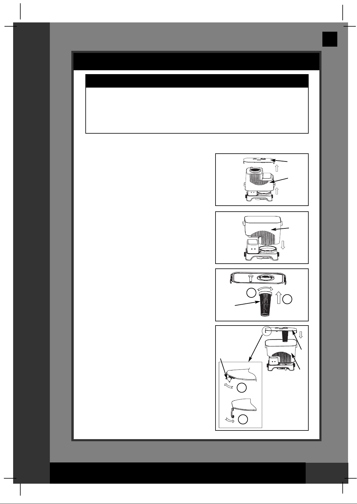
SET-UP INSTRUCTION
1. Assemble the above-ground-pool (AGP) and its filter pump per
installation instructions.
2. Remove the saltwater system and it’s
accessories from the packaging.
3. Lift up the saltwater tank from the
position it was stored in. See Fig. 1.
4. Flip the saltwater tank over. Press it
downward onto the base as shown.
Make sure the tank is securely
connected to the base. See Fig. 2.
5. In a clockwise motion screw the salt
container (7) to the underneath of
tank cover (3). See Fig. 3.
6. Attach the cover to the saltwater tank.
Lock the cover clips (4) on the handle
of the tank. See Fig. 4.
7. Connect the hose to the saltwater
pool system inlet. For installation: see
page 9 for 1-1/4" hose and page 10
for 1-1/2" hose connections.
Fig (1)
Fig (2)
Fig (3)
Fig (4)
2
1
2
1
3
3
9
4
9
9
7
IMPORTANT
• The saltwater system must be installed as the last piece of pool
equipment in the water return line to the pool as displayed in Fig. 6.
This location extends the life of the titanium plates.
• Disassemble the heater and accessories within the circulation line
before use.
Page 9

112
SAVE THESE INSTRUCTIONS
Page 9
(112) MODEL 6220 KRYSTAL CLEAN POOLWATER SYSTEM ENGLISH 7.5” X 10.5” PANTONE 295U 12/25/2006
For connection to filter pumps with 1-1/4” (32mm) hose size:
1. If your above-ground-pool is filled up with water, unscrew the strainer
grids from the strainer connectors and insert the black hat-like plugs
into the strainer connectors to prevent water from flowing out of pool.
Go to step 2 directly if your pool is empty.
2. If your above ground pool is equal
or higher than 42" (107cm) in height,
insert the water baffle adaptor A (14)
into the saltwater system outlet as
shown in Fig. 5. Go to step 3 directly
if your pool is lower than 42" (107cm)
in height.
3. Connect the adaptors A (15) to the
saltwater system as shown in Fig. 6.
Tighten securely.
NOTE: Make sure the LED lights on the saltwater system are facing out
from the pool during the installation as shown in Fig. 6.
4. Disconnect the water return (to the pool) hose from the filter pump
connection, and connect it to the adaptor A (15) on the saltwater
system outlet with a hose clamp. See Fig. 6.
5. Connect connector hose (17) to the filter pump outlet (lower connection)
and saltwater system inlet with hose clamps. Tighten securely.
6. Return strainer grids to strainer connectors inside pool after removing
black hat-like plugs that prevented water from flowing out of the pool.
SSEETT--UUPP IINNSSTTRRUUCCTTIIOONNSS
SET-UP INSTRUCTION (continued)
Fig (5)
14
NOTE: Remove the strainer at the pool inlet to allow the maximum flow rate of the
water to the pool.
Fig (6)
SWIMMING POOL
FILTER PUMP
15
16
15
16
17
Page 10

112
SAVE THESE INSTRUCTIONS
Page 10
(112) MODEL 6220 KRYSTAL CLEAN POOLWATER SYSTEM ENGLISH 7.5” X 10.5” PANTONE 295U 12/25/2006
SSEETT--UUPP IINNSSTTRRUUCCTTIIOONNSS
SET-UP INSTRUCTION (continued)
For connection to filter pumps with 1-1/2” (38mm) hose size:
Do not use adapter A (15)
1. If your above-ground-pool is filled with water, close the plunger valves
before saltwater system installation. Go to step 2 directly if your pool is
empty.
2. If your above ground pool is equal or
higher than 42" (107cm) in height,
insert the water baffle adaptor A (14)
into the saltwater system outlet as
shown in Fig. 5. Go to step 3 directly
if your pool is lower than 42" (107cm)
in height.
3. Disconnect the water return (to the
pool) hose from the filter pump
connection, and connect it to the
saltwater system outlet. See Fig. 7.
NOTE: Make sure the LED lights on the saltwater system are facing out
from the pool during the installation as shown in Fig. 7.
4. Connect connector hose (18) to the filter pump outlet (lower connection)
and saltwater system inlet. Tighten securely. See Fig. 7.
5. Open plunger valves to allow water to flow.
Fig (5)
14
NOTE: Remove the strainer at the pool inlet to allow the maximum flow rate of the
water to the pool.
Fig (7)
SWIMMING POOL
FILTER
PUMP
18
Page 11

112
SAVE THESE INSTRUCTIONS
Page 11
(112) MODEL 6220 KRYSTAL CLEAN POOLWATER SYSTEM ENGLISH 7.5” X 10.5” PANTONE 295U 12/25/2006
SSTTAATTIIOONNAARRYY MMOOUUNNTTIINNGG OOPPTTIIOONN
SALTWATER SYSTEM STATIONARY MOUNTING OPTION
Some countries, especially in the European community, require the product
to be secured to the ground or to a base in a permanent upright position.
Check your local authorities to determine if there is a regulation in your
area regarding above-the-ground swimming pool filter-pumps. If yes, then
the product can be mounted to a platform using the two (2) holes located in
the base. See drawing below.
The product can be mounted on a cement base or onto a wooden platform
to prevent accidental falling over. Total assembly must exceed 18kg.
1. The mounting holes are 8.2mm in diameter and spaced 180mm apart.
2. Use two bolts and lock nuts with a maximum of 8.2mm in diameter.
180mm
Page 12

112
SAVE THESE INSTRUCTIONS
Page 12
(112) MODEL 6220 KRYSTAL CLEAN POOLWATER SYSTEM ENGLISH 7.5” X 10.5” PANTONE 295U 12/25/2006
SALT & POOL WATER VOLUMES
Use only Fine Sodium Chloride Salts (table salt type)
Use only fine sodium chloride (NaCl) salt that is at least 99.8% pure. Do not use salt pellets or
crystals. Do not use iodized or yellow (yellow prussiate of soda) colored salt. The
electrolytic cell uses this salt to create the sanitizer. The purer the salt the better the performance
of the electrolytic cell.
Optimum Salt Concentrations
The ideal salt concentration in the saltwater tank is between 30,000-35,000 ppm (parts per
million). A low salt concentration will reduce the efficiency of the saltwater system and result in
low sanitizer production. High salt concentration may damage the power supply and cause
corrosion to pool metal fixtures and accessories. The best way to ensure the proper salt
concentration is to carefully follow these instructions.
How to Add Salt
NOTE: Only add salt for initial use and each time saltwater tank water is replenished.
1. Depress the ON button on the filter pump switch to circulate pool water.
2. Keep the saltwater system “OFF”.
3. In counter-clockwise motion unscrew and lift up the salt measuring scoop (1).
4. Using the salt measuring scoop, measure out four full
scoops of salt (total 1kg or 2.2lbs) into the salt
container (7). See Fig. 8.
5. Attach the salt measuring scoop to the cover, turn
clockwise and secure in place.
IMPORTANT
DO NOT add pool chemicals directly to the saltwater tank. This may damage the cell.
Fig (8)
1
Page 13

112
SAVE THESE INSTRUCTIONS
Page 13
(112) MODEL 6220 KRYSTAL CLEAN POOLWATER SYSTEM ENGLISH 7.5” X 10.5” PANTONE 295U 12/25/2006
6. Turn the water filling valve counterclockwise to
open the valve. Pool water will flow into the tank.
See Fig. 9.
7. When you see the red indicator on the cover pop
up, immediately turn the water filling valve
clockwise to close the valve. The tank should fill
in 3-4 minutes. See Fig. 10.
Fig (9)
SALT & POOL WATER VOLUMES (continued)
Fig (10)
2
1
IMPORTANT
DO NOT try to move the unit by holding the handles on
the tank when it is filled with water. This will cause the
salt water to flow out of the tank.
If you have unintentionally moved the unit in this way,
please immediately secure the tank to its right position.
Follow the manual’s instructions to add salt and water as
needed.
Page 14

112
SAVE THESE INSTRUCTIONS
Page 14
(112) MODEL 6220 KRYSTAL CLEAN POOLWATER SYSTEM ENGLISH 7.5” X 10.5” PANTONE 295U 12/25/2006
OOPPEERRAATTIINNGG IINNSSTTRRUUCCTTIIOONNSS
OPERATION INSTRUCTIONS
Before starting the saltwater system be sure that:
• The entire filtering and saltwater system is connected to a grounding type receptacle
protected by a ground-fault circuit interrupter (GFCI) or residual current device (RCD).
• The filter pump operates several minutes before starting the saltwater system (This
removes air pockets and debris in the water hoses).
• No air is trapped in any of the hoses (Follow the Filter Pump Owner’s manual to release
any trapped air).
1. Adjust the time control dial which is located at
the back of the electronic control station to the
suitable level for your pool size. See operation
time table. See Fig. 11.
NOTE: The operating time level is already set
in the factory if you are purchasing a pool set.
2. Switch on the unit. The left side green LED on
the control panel will light up.
3. The right side green LED light on the control
panel will light up about ten minutes after the
salt is thoroughly dissolved and mixed with
water, which indicates the saltwater system
has started chlorine production. The built-in
timer will now operate for the number of hours
selected at the same time each day.
NOTE: The saltwater system will not operate
if the filter pump is not operating.
4. The number of operating hours can be
re-adjusted as necessary. Switch off the
unit and adjust the time control dial.
5. The right side green LED light on the control panel will turn off when the cycle has
ended. The system automatically goes into a “Power Saving Mode” and will
automatically turn itself back on in 24 hours to continue its daily chlorine production.
Fig (11)
WARNING
• Risk of electric shock. Connect this product only to a grounding type receptacle
protected by a ground-fault circuit interrupter (GFCI) or residual current device (RCD).
Contact a qualified electrician if you cannot verify that the receptacle is protected by a
GFCI/RCD. Use a qualified electrician to install the GFCI/RCD, which has a maximum
rate of 30mA. Do not use a portable residual current device (PRCD).
• To reduce the risk of electric shock, do not use extension cords, timers, plug adaptors or
converter plugs to connect unit to electric supply; provide a properly located outlet.
• Do not attempt to plug in or unplug this product while standing in water or when your
hands are wet.
• Position this product away from pool to prevent a child from climbing on pump to
access the pool.
• Do not operate this product when pool is occupied.
• Operating this product without water flowing through the system can cause a build up
of flammable gases which can result in FIRE OR EXPLOSION.
2
1
Level
Operation Time (Hours)
1
1
2
2
3
4
4
6
5
12
Level and Operation Time
Page 15

112
SAVE THESE INSTRUCTIONS
Page 15
(112) MODEL 6220 KRYSTAL CLEAN POOLWATER SYSTEM ENGLISH 7.5” X 10.5” PANTONE 295U 12/25/2006
INTEX POOLS OPERATING TIME TABLE
Numbe
r of
days
can be
used
This table shows the operating time required for normal use of the Saltwater
System with above ground pools.
Pool Size
EASY SET™
POOL
ROUND
METAL
FRAME POOL
ULTRA FRAME™
POOL
Water Capacity
(
Calculated at 90% for
Frame Pool
and 80% for Easy Set
& Oval Pool)
(Gals)
(Liters)
INTEX ABOVE GROUND POOLS (AGP’s)
639 2419 1 4
1018 3853 1 4
1485 5621 1 4
1779 6734 2 3
2587 9792 2 3
2822 10681 2 3
3284 12430 2 3
3736 14141 3 1
3754 14209 3 1
4273 16173 3 1
4614 17464 3 1
4786 18115 3 1
5455 20647 3 1
5894 22309 3 1
1185 4485 1 4
1718 6503 1 4
2086 7896 2 3
2454 9288 2 3
3282 12422 2 3
3861 14614 3 1
4440 16805 3 1
5061 19156 3 1
6423 24311 4 1
6981 26423 4 1
12481 47241 5 1
5061 19156 3 1
6981 26423 4 1
8' x 30" (244cm x 76cm)
10' x 30" (305cm x 76cm)
12' x 30" (366cm x 76cm)
12' x 36" (366cm x 91cm)
15' x 33" (457cm x 84cm)
15' x 36" (457cm x 91cm)
15' x 42" (457cm x 107cm)
15' x 48" (457cm x 122cm)
16' x 42" (488cm x 107cm)
16' x 48" (488cm x 122cm)
16' x 52" (488cm x 132cm)
18' x 42" (549cm x 107cm)
18' x 48" (549cm x 122cm)
18' x 52" (549cm x 132cm)
10' x 30" (305cm x 76cm)
12' x 30" (366cm x 76cm)
12' x 36" (366cm x 91cm)
12' x 42" (366cm x 107cm)
15' x 36" (457cm x 91cm)
15' x 42" (457cm x 107cm)
15' x 48" (457cm x 122cm)
16' x 48" (488cm x 122cm)
18' x 48" (549cm x 122cm)
18' x 52" (549cm x 132cm)
24' x 52" (732cm x 132cm)
16' x 48" (488cm x 122cm)
18' x 52" (549cm x 132cm)
Number of
days before
salt and water
replenishment
Level
(Days)
(Approximate)
Page 16

112
SAVE THESE INSTRUCTIONS
Page 16
(112) MODEL 6220 KRYSTAL CLEAN POOLWATER SYSTEM ENGLISH 7.5” X 10.5” PANTONE 295U 12/25/2006
INTEX POOLS OPERATING TIME TABLE (continued)
NON-INTEX POOLS
Non-Intex Pools Operating Time Table
This table shows the operating time required for normal use of the Saltwater System with above ground pools.
Pool Size
RECTANGULAR
METAL FRAME POOL
RECTANGULAR
ULTRA FRAME™
POOL
OVAL FRAME
POOL
SMALL
RECTANGULAR
METAL FRAME
POOL
Water Capacity
(
Calculated at 90% for
Frame Pool
and 80% for Easy Set
& Oval Pool)
(Gals)
(Liters)
INTEX ABOVE GROUND POOLS (AGP’s)
4545 17203 3 1
14364 54368 5 1
4545 17203 3 1
8403 31805 4 1
14364 54368 5 1
2032 7691 2 3
2885 10920 2 3
4393 16628 3 1
5407 20465 3 1
6420 24300 4 1
6925 26211 4 1
439 1662 1 4
603 2282 1 4
1013 3834 1 4
1373 5197 1 4
1907 7218 2 3
18' x 9' x 52" (549cm x 274cm x132cm)
32' x 16' x 52" (975cm x 488cm x132cm)
18' x 9' x 52" (549cm x 274cm x132cm)
24' x 12' x 52" (732cm x 366cm x132cm)
32' x 16' x 52" (975cm x 488cm x132cm)
16' x 8' x 42" (488cm x 244cm x107cm)
18' x 10' x 42" (549cm x 305cm x107cm)
20' x 12' x 48" (610cm x 366cm x122cm)
24' x 12' x 48" (732cm x 366cm x122cm)
28' x 12' x 48" (853cm x 366cm x122cm)
28' x 12' x 52" (853cm x 366cm x132cm)
86-5/8" x 59" x 23-5/8" (220cm x 150cm x 60cm)
102-1/2" x 63" x 25-5/8" (260cm x 160cm x 65cm)
118" x 78-3/4" x 29-1/2" (300cm x 200cm x 75cm)
149-5/8" x 78-3/4" x 31-1/2" (380cm x 220cm x 80cm)
177-1/4" x 86-5/8" x 33-1/2" (450cm x 220cm x 85cm)
Level
(Days)
(Approximate)
Number of
days before
salt and water
replenishment
NOTE: The tank may be drained in less than the number of days shown depending on the actual flow rate of water through
the system. The flow rate is dependent on filter-pump size, pool size, filter cartridge condition (a dirty filter reduces the flow
rate considerably) and pool water level. Accordingly, check the volume of water in the tank on a regular basis. For example,
if you are operating the system on level 1 (1 hour of daily operation), you should check the tank level 4 days after filling and
daily after that until empty. If the tank is draining very slowly (6 days or longer) or too fast (2 days or faster), please see the
trouble shooting guide.
396 to 1717 1500 to 6500 1 4
1717 to 3302 6501 to 12500 2 3
3302 to 5944 12501 to 22500 3 1
5944
to 8454 22501 to 32000 4 1
8454 to 14529 32001 to 55000 5 1
Pool Water Capacity
(Gals)
(Liters)
Level
Number of
days before
salt and water
replenishment
(Days)
(Approximate)
Page 17

112
SAVE THESE INSTRUCTIONS
Page 17
(112) MODEL 6220 KRYSTAL CLEAN POOLWATER SYSTEM ENGLISH 7.5” X 10.5” PANTONE 295U 12/25/2006
Minimum Water Level
The water level in the tank may be drop to or below the “MIN” line
marked on the inner wall depending on the actual flow rate of water
through the system. The flow rate is dependent on filter-pump size,
pool size, filter cartridge condition (a dirty filter reduces the flow rate
considerably) and pool water level. When the tank cannot be drained
anymore and the water level stopped at or below the “MIN” line,
replenishes salt and water by following the manual’s instruction.
OPERATION INSTRUCTIONS (continued)
Minimum
Water Level
OOPPEERRAATTIINNGG IINNSSTTRRUUCCTTIIOONNSS
MIN
22.5 L
6 GAL
2 GAL
7.5 L
Page 18

112
SAVE THESE INSTRUCTIONS
Page 18
(112) MODEL 6220 KRYSTAL CLEAN POOLWATER SYSTEM ENGLISH 7.5” X 10.5” PANTONE 295U 12/25/2006
OOPPEERRAATTIINNGG IINNSSTTRRUUCCTTIIOONNSS
OPERATION INSTRUCTIONS (continued)
SPECIAL NOTES
• Always use a test strip to test the sanitizer level before entering or using
the pool. Standard chlorine test strips will measure the active sanitizer
level in the pool water. If the test strip indicates the chlorine level is too
high, wait until the indicated chlorine level drops below 3 ppm
before using the pool or operating the saltwater system again.
• Heavy pool usage, and higher temperatures may require higher chlorine
output (longer operation time) to maintain proper free available chlorine
residuals.
• If a power outage occurs or the power cord is unplugged then the
saltwater system operating hours will reset to the time of day
corresponding with power being restored. Make sure that the pump is
operating at the same time.
WARNING
• NEVER use the pool if indicated chlorine level is more
than 3 ppm.
• Do not operate saltwater system while the pool is in use
or occupied.
Pool Volume Calculation
Rectangular Length x Width x Average Depth x 7.5 Length x Width x Average Depth
Circular Length x Width x Average Depth x 5.9 Length x Width x Average Depth x 0.79
Oval Length x Width x Average Depth x 6.0 Length x Width x Average Depth x 0.80
Types of Pool
Gallons
(pool size in feet)
Cubic Meters
(pool size in meters)
Page 19

112
SAVE THESE INSTRUCTIONS
Page 19
(112) MODEL 6220 KRYSTAL CLEAN POOLWATER SYSTEM ENGLISH 7.5” X 10.5” PANTONE 295U 12/25/2006
ALARMS
Automatic Alarms
No sanitizer production will occur if “Low Water Flow”, “Low SaltWater Level
in the saltwater tank” or “High Salt Concentration” conditions are detected. If
any of these conditions occur then the saltwater system will sound an alarm
that indicates sanitizer production has stopped. A buzzer will sound for an
hour and the right side red LED on the control panel will light up. The
saltwater system will go to power saving mode.
Turn off the power of the unit and follow the solutions below in order to
solve the problem. Turn on the unit again by following the “Operating
Instructions”.
CHECK CAUSE
1. Low
Water
Flow
or No
Flow
2.
Low
Saltwater
Level or
No
Saltwater
3.
High Salt
Concentration
1. Circulation line
blocked.
2. Incorrect inlet
and outlet hose
direction.
3. Flow sensor
failure.
1. Saltwater ran out
in the saltwater
tank.
1. Added too much
salt or not filled
with enough
water.
2. Possible motor or
electrolytic cell
failure.
Ye s Ye s
Ye s Ye s
Ye s Ye s
• Ensure the plunger valves are
opened (if any).
• Ensure your filter cartridge is
clear from debris and dirt. See
Filter Pump Manual.
• Release all trapped air in the
circulation line. See Filter
Pump Manual.
• Check for the direction of water
inlet and water outlet hose.
Reverse the hoses if necessary.
See “Set Up Instructions”.
• Contact Intex Service Center
for replacement.
• Drain out all the water in the
saltwater tank. Refill water and
add salt in the saltwater tank. See
"How to Add or Remove Salt".
• Drain out all the water in the
saltwater tank. Refill water and
add salt in the saltwater tank. See
"How to Add or Remove Salt".
• Contact Intex Service Center.
Replace the cell if needed.
BUZZERREMEDY
RIGHT
LED
LIGHT
AALLAARRMMSS
Page 20

112
SAVE THESE INSTRUCTIONS
Page 20
(112) MODEL 6220 KRYSTAL CLEAN POOLWATER SYSTEM ENGLISH 7.5” X 10.5” PANTONE 295U 12/25/2006
Removing Salt
If too much salt has been added, a buzzer will sound for an hour and the
right side red LED on the control panel will light up (see “Alarm Handling”).
The water in the saltwater tank must be replaced as follows:
1. Check local regulations for specific directions regarding disposal of
swimming pool water. Note that salt water can damage grass, plants,
etc.
2. Open the tank cover (3). See Fig. 12.
3. Check to make sure that the drain
valve plug (10) inside the saltwater
tank is plugged in place. See Fig. 13.
4. Remove the drain valve cap (11) from
the drain valve on the outside saltwater
tank wall.
Fig (12)
Fig (13)
3
10
11
ALARMS (continued)
IMPORTANT
Close plunger valves or insert black hat-like plugs in strainer opening to
prevent water spillage. Open plunger valves or remove plugs when
maintenance is completed.
AALLAARRMMSS
WARNING
Always unplug this product from the electrical outlet before removing,
cleaning, servicing or making any adjustment to the product.
Page 21

112
SAVE THESE INSTRUCTIONS
Page 21
(112) MODEL 6220 KRYSTAL CLEAN POOLWATER SYSTEM ENGLISH 7.5” X 10.5” PANTONE 295U 12/25/2006
5. Attach the female end of the
garden hose to the drain
connector (19). See Fig. 14.
6. Place the other end of the hose in
an area where the water can be
safely drained away from the
house, plants, etc.
7. Insert the drain connector (19) to
the drain valve. See Fig. 15.
NOTE: The drain connector will
push the drain valve plug (10)
open inside the tank and water
will start to drain immediately.
8. Disconnect hose and drain
connector (19) when finished.
9. Re-insert drain valve plug (10) in
drain valve on inside of saltwater
tank.
10. Replace drain valve cap (11) on
outside of saltwater tank.
11. Follow "Adding Salt" procedure.
Fig (15)
Fig (14)
19
10
ALARMS (continued)
AALLAARRMMSS
Page 22

112
SAVE THESE INSTRUCTIONS
Page 22
(112) MODEL 6220 KRYSTAL CLEAN POOLWATER SYSTEM ENGLISH 7.5” X 10.5” PANTONE 295U 12/25/2006
SALTWATER TANK, SALT CONTAINER AND WATER FILTERS CLEANING
MMAAIINNTTEENNAANNCCEE
Clean the saltwater tank, salt container, and water filters every 2
weeks.
1. Drain all water out from the saltwater tank. See "Removing Salt".
2. Remove tank cover (3) and lift the saltwater tank (9) off of the base unit.
3. Flip the saltwater tank over with the
saltwater tank filter (8) facing up. See
Fig. 16.
4. Flush out any dirt or debris by using a
garden hose.
5. Remove the salt container (7) by
unscrewing as shown. See Fig. 17.
6. Clean the salt container net (6) and
salt container (7) to remove dirt,
debris or caked salt. See Fig. 18.
7. Attach the net and container.
8. In a counter-clockwise motion unscrew
the water filter (12) and remove it from
the base unit. See Fig. 19.
9. Rub the net to crush the small particles
(if any) and flush out the dirt by using a
garden hose.
10. Attach the water filter.
11. Assemble the tank to the base unit
and press it downward. Make sure the
tank is securely connected to the base.
12. Attach the tank cover.
Fig (16)
Fig (17)
Fig (19)
Fig (18)
12
6
7
Page 23

112
SAVE THESE INSTRUCTIONS
Page 23
(112) MODEL 6220 KRYSTAL CLEAN POOLWATER SYSTEM ENGLISH 7.5” X 10.5” PANTONE 295U 12/25/2006
LONG TERM STORAGE
MMAAIINNTTEENNAANNCCEE
1. Disconnect power cord from electrical outlet.
2. After pool is emptied of all water, disconnect the Saltwater Pool
System/Filter Pump from the pool hose, reversing the installation
instructions.
3. Air-dry the unit before storage.
4. Store the unit and accessories in a dry, temperature controlled,
between 41 degrees Fahrenheit (5 degrees Celsius) and 100 degrees
Fahrenheit (38 degrees Celsius) storage location.
5. The original packing carton can be used for storage.
3-Way Test Strips can test the sanitizer level as “Free Chlorine”, “pH”, and
“Total Alkalinity” levels at the same time. Directions and Use:
1. Dip entire strip into water and remove immediately.
2. Hold strip level for 15 seconds (do not shake excess water from strip).
3. Compare free chlorine, pH and total alkalinity strip pad to the color chart
on packaging label. Adjust pool water as necessary. Proper technique is
important for water testing. Be sure to read and follow the written strip
instructions.
INTEX®3-WAY TEST STRIPS (PACKED WITH THE PRODUCT)
Page 24

112
SAVE THESE INSTRUCTIONS
Page 24
(112) MODEL 6220 KRYSTAL CLEAN POOLWATER SYSTEM ENGLISH 7.5” X 10.5” PANTONE 295U 12/25/2006
POOL MAINTENANCE & CHEMICAL DEFINITIONS
MMAAIINNTTEENNAANNCCEE
Preferred Water Chemistry Reading
Minimum Ideal Maximum
Free Chlorine 0 1.0 - 3.0 ppm 3.0 ppm
Combined Chlorine 0 0 0.2 ppm
pH 7.2 7.4 - 7.6 7.8
Total Alkalinity 100 ppm 100 - 140 ppm 140 ppm
Calcium Hardness 150 ppm 200 - 400 ppm 500 - 1000 ppm
Stabilizer (Cyanuric Acid) 10 ppm 30 - 50 ppm 150 ppm
Free Chlorine - Is the sanitizer (HOCL) present in pool water.
Combined Chlorine - Is formed by the reaction of free chlorine with ammonia
wastes.
Result if too high - Sharp chlorinous odor, eye irritation.
pH - A value that indicates how acidic or basic a solution is.
Result if too low - Corroded metals, eye & skin irritation,
destruction of total alkalinity.
Result if too high - Scale formation, cloudy water,
shorter filter runs, eye & skin
irritation, poor chlorine efficiency.
Total Alkalinity - Indicates the degree of the water's resistance to change
in pH. It determines the speed and ease of pH change,
so always adjust total alkalinity before adjusting the pH
level.
Result if too low - Corroded metals, eye & skin irritation.
Low alkalinity will cause the pH to be
unstable. Any chemical added to the
water will have an affect on pH.
Result if too high - Scale formation, cloudy water,
eye & skin irritation, poor chlorine
efficiency.
Calcium Hardness - Refers to the amount of calcium and magnesium
dissolved in the water.
Result if too high - Scale will form and will cause the
water to become cloudy.
Stabilizer - Stabilizers extend the life of chlorine in swimming
(Cyanuric Acid) pools.
• Maintaining high salt and sanitizer levels above recommended range can
contribute to corrosion of pool equipment.
• Check the expiry date of the test kit as test results may be inaccurate if used
after that date.
• If additional sanitizer is required due to heavy bather load, use a pool sanitizer
based on Trichloro-s-triazinetrione or sodium dichloro-s-triazinetrione dihydrate.
HOCL - A very effective killer of algae and bacteria known as hypochlorous acid.
Page 25

112
SAVE THESE INSTRUCTIONS
Page 25
(112) MODEL 6220 KRYSTAL CLEAN POOLWATER SYSTEM ENGLISH 7.5” X 10.5” PANTONE 295U 12/25/2006
TROUBLESHOOTING GUIDE
IMPORTANT
If you continue to experience difficulty, please contact our Consumer Service
Department for assistance. See back cover for contact information.
INSUFFICIENT
SANITIZER
WHITE
FLAKES
IN THE WATER
SALT WATER
LEVEL INSIDE
THE SALTWATER
TANK DROP
TOO SLOW.
SALT WATER
LEVEL INSIDE
THE SALTWATER
TANK DROP
TOO FAST.
• Insufficient operating hours of
the saltwater system.
• Insufficient salt concentration
in the saltwater tank.
• Sanitizer loss due to intense
sunlight exposure.
• The bather load has
increased.
• Excessive calcium hardness is
present in pool water.
• Forgot to install baffle adaptor.
• Filter cartridge dirty.
• Heater or the other
accessories are in use
simultaneously.
• Pool water level is too low.
• Increase the saltwater system operating
time per day. See “Operating
Instructions”.
• Drain out all the water in the saltwater
tank. Refill water and add salt in the
saltwater tank. See "How to Add or
Remove Salt".
• Use Pool Cover when the pool is not
use and/or when the unit is operating.
• Increase the saltwater system operating
time per day. See “Operating
Instructions”.
• Drain about 20 to 25% of the pool water
and add fresh water to decrease the
calcium hardness.
• If the pool height is 42" and above,
read manual instruction and install the
suitable size of baffle adaptor.
• Clean or replace the cartridge.
• Disassemble the heater and accessories
within the circulation line.
• Fill the pool with more water.
• Remove the baffle adapter B from the
saltwater system outlet (if any).
REMEDY
CAUSE
PROBLEM
Page 26

112
SAVE THESE INSTRUCTIONS
Page 26
(112) MODEL 6220 KRYSTAL CLEAN POOLWATER SYSTEM ENGLISH 7.5” X 10.5” PANTONE 295U 12/25/2006
SSAAFFEETTYY GGUUIIDDEELLIINNEESS
GENERAL AQUATIC SAFETY
Water recreation is both fun and therapeutic. However, it involves
inherent risks of injury and death. To reduce your risk of injury, read
and follow all product, package and package insert warnings and
instructions. Remember, however, that product warnings, instructions
and safety guidelines cover some common risks of water recreation,
but do not cover all instances or risk and or danger.
For additional safeguards, also familiarize yourself with the following
general guidelines as well as guidelines provided by nationally
recognized Safety Organizations:
• Demand constant supervision.
• Learn to swim.
• Take the time to learn CPR and first aid.
• Instruct anyone who is watching your children about potential pool
hazards and about the use of protective devices such as locked doors,
barriers, etc.
• Teach children what to do in case of an emergency.
• Always use common sense and good judgement when enjoying any
water activity.
• Supervise, Supervise, Supervise.
Page 27

112
SAVE THESE INSTRUCTIONS
Page 27
(112) MODEL 6220 KRYSTAL CLEAN POOLWATER SYSTEM ENGLISH 7.5” X 10.5” PANTONE 295U 12/25/2006
LIMITED WARRANTY
Your Krystal Clean Poolwater™ System has been manufactured using the highest quality
materials and workmanship. All Intex products have been inspected and found free of
defects prior to leaving the factory. This Limited Warranty applies only to the Krystal Clean
Poolwater™ System.
The provisions of this Limited Warranty apply only to the original purchaser and is not
transferable. This Limited Warranty is valid for a period of one (1) year from the date of the
initial retail purchase. Keep your original sales receipt with this manual, as proof of
purchase will be required and must accompany warranty claims or the Limited Warranty is
invalid.
If a manufacturing defect is found within this one (1) year period, please contact the
appropriate Intex Service Center listed in this manual. The Service Center will determine
the validity of the claim.
IMPLIED WARRANTIES ARE LIMITED TO THE TERMS OF THIS WARRANTY AND IN
NO EVENT SHALL INTEX, THEIR AUTHORIZED AGENTS OR EMPLOYEES BE LIABLE
TO THE BUYER OR ANY OTHER PARTY FOR DIRECT OR CONSEQUENTIAL
DAMAGES OR LIABILITIES.
This Limited Warranty does not apply if the Krystal Clean Poolwater™ System is subject to
negligence, abnormal use or operation, accident, improper operation, improper voltage or
current contrary to operating instructions, or to damage by circumstances beyond Intex’s
control, including but not limited to, ordinary wear and tear and damage caused by
exposure to fire, flood, freezing, rain, or other external environmental forces. This Limited
Warranty applies only to those parts and components sold by Intex. The Limited Warranty
does not cover unauthorized alterations, repairs or disassembly by anyone other than Intex
Service Center personnel.
The costs associated with the loss of pool water, chemicals or water damage are not
covered by this warranty. Injury or damage to any property or person is not covered by this
warranty.
Page 28

112
SAVE THESE INSTRUCTIONS
Page 28
(112) MODEL 6220 KRYSTAL CLEAN POOLWATER SYSTEM ENGLISH 7.5” X 10.5” PANTONE 295U 12/25/2006
• CHILE / ARGENTINA / COMEXA S.A
PERU / URUGUAY SAN IGNACIO 0201, PARQUE
INDUSTRIAL PORTEZUELO,
QUILICURA, SANTIAGO, CHILE
TEL: 56-2-339 9000
FAX: 56-2-339 9022
E-mail: generalsilfa@silfa.cl
• SAUDI ARABIA SAUDI ARABIAN MARKETING &
AGENCIES CO. LTD.
PRINCE AMIR MAJED STREET,
AL-SAFA DISTRICT. JEDDAH,
KINGDOM OF SAUDI ARABIA
TEL: 966-2-693 8496
FAX: 966-2-271 4084
E-mail: abid.syed@samaco.com.sa
Website: www.samaco.com.sa
• AUSTRIA STEINBACH GMBH AUSTRIA
AISTINGERSTRAßE 2
4311 SCHWERTBERG
TEL: 0800 468397665
FAX: 07262 61439-0
E-mail: service@intexcorp.at
Website: www.intexcorp.at
• CZECH REPUBLIC / INTEX TRADING S.R.O.
EASTERN EUROPE BENESOVSKA 23,
101 00 PRAHA 10
CZECH REPUBLIC
TEL: 420-2-717 32247
FAX: 420-2-673 12552
E-mail: info@intexcorp.cz
• BELGIUM N.V. NICOTOY S.A.
MOESKROENSESTEENWEG 383 C,
8511 AALBEKE
TEL: 0800 92088
FAX: 32-56.20.37.61
E-mail: intex@nicotoy.be
• DENMARK K.E. MATHIASEN A/S
SINTRUPVEJ 12
DK-8220 BRABRAND
DENMARK
TEL: +45 89 44 22 00
FAX: +45 86 24 02 39
E-mail: intex@keleg.dk
• SWEDEN LEKSAM AB
BRANDSVIGSGATAN 6,
S-262 73 ÄNGELHOLM,
SWEDEN
TEL: +46 431 44 41 20
FAX: +46 431 190 35
E-mail: kundtjanst@leksam.se
• NORWAY NORSTAR AS
PINDSLEVEIEN 1
N-3221 SANDEFJORD
NORWAY
TEL: +47 33 48 74 10
FAX: +47 33 48 74 11
E-mail: intex@norstar.no
• FINLAND NORSTAR OY
RUUKINTIE 20
FIN-02330 ESPOO
FINLAND
TEL: +358 9 8190 530
FAX: +358 9 8190 5335
E-mail: info@norstar.fi
• RUSSIA LLC BAUER
KIEVSKAYA STR., 20,
121165 MOSCOW, RUSSIA
TEL: 095-249-9400/8626/9802
FAX: 095-742-8192
E-mail: intex@rdm.ru
Website: www.intex.su
• POLAND KATHAY HASTER
UL. LUTYCKA 3,
60-415 POZNAN
TEL: +48 61 8498 381/380
FAX: +48 61 8474 487
E-mail: inx@kathay.com.pl
• HUNGARY RECONTRA LTD.
H-1113 BUDAPEST, DARÓCZI ÚT 1-3,
HUNGARY
TEL: +361 372 5200/113
FAX: +361 209 2634
E-mail: gizi@recontra.hu
• BRAZIL KONESUL MARKETING & SALES LTDA
RUA INÁCIO BORBA, 835 - CEP. 04715-020,
CHÁCARA SANTO ANTONIO - SÃO
PAULO - SP - BRASIL
TEL: 55 (11) 5183 8866
FAX: 55 (11) 5183 8866
E-mail: konesulintex@uol.com.br
• ASIA INTEX DEVELOPMENT CO. LTD.
8TH FLOOR,
DAH SING FINANCIAL CENTRE,
108 GLOUCESTER ROAD,
WANCHAI, HONG KONG
TEL: 852-28270000
FAX: 852-23118200
E-mail: xmservicesupport@intexcorp.com.cn
Website: www.intexdevelopment.com
• EUROPE INTEX TRADING B.V.
POSTBUS 1075, 4700 BB ROOSENDAAL,
THE NETHERLANDS
TEL: 31-(0)165-593939
FAX: 31-(0)165-593969
E-mail: service@intexcorp.nl
Website: www.intexcorp.nl
• FRANCE INTEX SERVICE (FRANCE) SAS
52, ROUTE NATIONALE
39190 BEAUFORT, FRANCE
TEL: 08 90 71 20 39 (0.15 TTC/min)
FAX: 03 84 25 18 09
E-mail: sav@intexcorp.com.fr
Website: www.intex.fr
• GERMANY STEINBACH GMBH GERMANY
AN DER WELLE 4
60322 FRANKFURT
TEL: 0800 468397665
FAX: 07262 61439-0
E-mail: service@intexcorp.de
Website: www.intexcorp.de
• ITALY A& A MARKETING SERVICE
OFFICE: VIA DEI MESTIERI 8, 20049
CONCOREZZO, MILANO - ITALY
TEL: 39-039-6886260
FAX: 39-039-6043603
E-mail: intex@aeamarketingservice.com
Website: www.intexitalia.com
WAREHOUSE: C/O ALVI, VIALE DELLA
REPUBBLICA 10 - 27100 PAVIA - ITALY
• UK TOY BROKERS LTD
MARKETING HOUSE,
BLACKSTONE ROAD
HUNTINGDON, CAMBS.
PE29 6EF. UK
TEL: 01480 414361
FAX: 01480 414761
E-mail: sales@toybrokers.com
Website: www.toybrokers.com
• SWITZERLAND GWM AGENCY
GARTEN-U. WOHNMÖBEL
RÄFFELSTRASSE 25
POSTFACH
CH-8045 ZURICH/SWITZERLAND
TEL: + 41 - (0)900 - 455 456
FAX: 41 44 455 50 65
E-mail: gwm@gwm.ch
Website: www.gwm.ch
• SPAIN / PORTUGAL KOKIDO BVI LIMITED
C/PLOMO 5-7, NAVE 19 POLÍGONO
INDUSTRIAL AIMAYR SAN MARTÍN DE
LA VEGA 28330 MADRID SPAIN
TEL: 34-90-2351045
FAX: 34-91-6912709
E-mail: belen@kokido.com
E-mail: info@kokido.com
• AUSTRALIA HUNTER OVERSEAS PTY LTD
LEVEL 1, 225 BAY STREET,
BRIGHTON, VICTORIA
AUSTRALIA
TEL: 61-3-9596-2144 or 1800-224-094
FAX: 61-3-9596-2188
E-mail: enquiries@hunteroverseas.com.au
• NEW ZEALAND HAKA NEW ZEALAND LIMITED
UNIT 5, SENTINEL PARK,
25 AIRBORNE ROAD, ALBANY
PO BOX 302171,
NORTH HARBOUR,
AUCKLAND 1330
NEW ZEALAND
TEL: 649-4159213
FAX: 649-4159212
E-mail: geoff@hakanz.co.nz
• MIDDLE EAST FIRST GROUP TRADING
REGION AL MOOSA GROUP BUILDING, 1ST
FLOOR, OFFICE 102 & 103, UMM HURAIR
ROAD, KARAMA, DUBAI, UAE
TEL: 00971-4-3373322
FAX: 00971-4-3375115
E-mail: info@firstgrouptrading.com
Website: www.firstgrouptrading.com
• SOUTH AFRICA WOOD & HYDE
15-17 PACKER AVENUE, INDUSTRIA 2,
CAPE TOWN, SOUTH AFRICA 7460
TEL: 27-21-0800-204-692
FAX: 27-21-505-5600
E-mail: ygoldman@thumb.co.za
AREAS LOCATION AREAS LOCATION
For service questions or to order replacement parts, please contact the appropriate office
listed below or visit www.intexdevelopment.com for answers to most frequently asked
questions.
 Loading...