

Intesity IDIC-024KF-3, IDIC-024KC-3, IDIC-048KC-3, IDIC-036KF-3, IDIC-060KF-3 Installation Instructions Manual
...
IDIC-024KF-3 - IDIC-024KC-3 / IDIC-036KF-3 - IDIC-036KC-3,
IDIC-048KF-3 - IDIC-048KC-3 / IDIC-060KF-3 - IDIC-060KC-3.
INSTALLATION INSTRUCIONS
intensity.mx
MAN-I-IDC-1214
SPLIT SYSTEM HEAT PUMP & AIR CONDITIONER
2, 3, 4 Y 5 TR.
FEATURING R-410A REFRIGERANT
18 SEER
TABLE OF CONTENTS
1.0 SAFETY..................................................................................................................3
1.1 INSPECTION.................
................................................................................
...4
1.2 LIMITATIONS..........................................................
..............................
............4
2.0 GENERAL..............................................................................................................4
3.0 UNIT INSTALLATION............................................................................................6
3.1 LOCATION.......................................................................................................6
3.2 GROUND INSTALLATION...............................................................................6
3.3 ROOF INSTALLATION.............................
........................................................
6
3.4 UNIT PLACEMENT..........................................................................................6
3.5 UNIT LOCATION CONSIDERATIONS............................................................7
3.6 UNIT MOUNTING............................................................................................8
3.7 FACTORY-PREFERRED TIE-DOWN METHOD.............................................9
3.8 PRECAUTIONS DURING LINE INSTALLATION.............................................9
3.9 PRECAUTIONS DURING BRAZING OF LINES...
..........................................11
3.10 PRECAUTIONS DURING BRAZING SERVICE VALVE...............................11
4.0 INTERCONNECTING TUBING............................................................................12
4.1 SUCTION AND LIQUID LINES .....................................................................12
4.2 MAXIMUM LENGTH OF LINES ....................................................................13
4.3 VERTICAL LIFT ............................................................................................13
5.0 EVACUATION......................................................................................................13
6.0 ELECTRICAL CONNECTIONS...........................................................................14
6.1 GENERAL INFORMATION & GROUNDING ............
...............................
......14
6.2 FIELD CONNECTIONS POWER WIRING ..............................
......................
14
6.3 REMOVING THE TOP PANEL AND MOTOR................................................15
7.0 CHECKING REFRIGERANT CHARGE .............................................................16
7.1 CHARGING BY LIQUID PRESSURE............................................................16
7.2 CHARGING BY WEIGHT ..............................................................................16
7.3 FINAL LEAK TESTING .................................................................................16
8.0 SYSTEM OPERATION........................................................................................18
8.1 COMPRESSOR CRANKCASE HEATER (CCH)...........................................19
8.2 REVERSING VALVE INTRODUCTION .......................................................20
8.3 PROTECTION FUNCTION INTRODUCTION...............................................20
8.4 SENSORS.....................................................................................................20
8.5 ERROR CODE TABLE..................................................................................24
8.6 PARAMETER POINT CHECK TABLE...........................................................25
9.0 WARRANTY.........................................................................................................26
9.1 MAINTENANCE.............................................................................................26
10.0 WIRING DIAGRAM............................................................................................26
10.1 CONTROL WIRING FOR UNITS.................................................................26
2
WARNING
These instructions are intended as an aid to qualified
licensed service personnel for proper installation, adjustment and operation of this unit. Read these instructions
thoroughly before attempting installation or operation.
Failure to follow these instructions may result in improper
installation, adjustment, service or maintenance possibly
resulting in fire, electrical shock, property damage,
personal injury or death.
RECOGNIZE THIS SYMBOL AS AN INDICATION OF IMPORTANT SAFETY INFORMATION
DO NOT DESTROY THIS MANUAL
Please read carefully and keep in a safe place for future reference by a serviceman.
1.0 SAFETY
This is a safety alert symbol. When you see this symbol on labels or in
manuals, be alert to the potential for personal injury.
Understand and pay particular attention to the signal words DANGER, WARNING, or
CAUTION.
DANGER indicates an imminently hazardous situation, which, if not avoided, will result
in death or serious injury.
WARNING indicates a potentially hazardous situation, which, if not avoided, could result
in death or serious injury.
CAUTION indicates a potentially hazardous situation, which, if not avoided may result
in minor or moderate injury. It is also used to alert against unsafe practices and hazards
involving only property damage.
This is an attention alert symbol. When you see this symbol on labels or in
manuals, be alert to the potential for personal injury.
This document is customer property and is to remain with this unit.
These instructions do not cover all the different variations of systems nor does
it provide for every possible contingency to be met in connection with installation.
All phases of this installation must comply with NATIONAL, STATE, AND LOCAL
CODES. If additional information is required please contact your local distributor.
3
WARNING
Improper installation may create a condition where the operation of the product
could cause personal injury or property damage.
Improper installation, adjustment, alteration, service or maintenance can cause
injury or property damage. Refer to this manual for assistance or for additional
information, consult a qualified contractor, installer or service agency.
CAUTION
This product must be installed in strict compliance with the installation instructions and any applicable local, state, and national codes including, but not
limited to building, electrical, and mechanical codes.
WARNING
FIRE OR ELECTRICAL HAZARD
Failure to follow the safety warnings exactly could result in serious injury, death
or property damage.
A fire or electrical hazard may result causing property damage, personal injury
or loss of life.
CAUTION
If using existing refrigerant lines make certain that all joints are brazed, not
soldered.
CAUTION
Scroll compressor dome temperatures may be hot. Do not touch the top of compressor; it may cause minor to severe burning.
The outdoor units are designed to be connected to a matching indoor coil with braze
connect lines. Units are factory charged with refrigerant for a matching indoor coil
plus 15 feet of field supplied lines.
Matching indoor coils are available with a thermostatic expansion valve or an orifice
for the most common usage. The orifice size and/or refrigerant charge may need to
be changed for some indoor-outdoor unit combinations, elevation differences or
total line lengths.
2.0 GENERAL
1.Limitations for the indoor unit, coil and appropriate accessories must also be observed.
2.The outdoor unit must not be installed with any duct work in the air stream. The outdoor fan is
the propeller type and is not designed to operate against any additional external static pressure.
3.The maximum and minimum conditions for operation must be observed to assure a system
that will give maximum performance with minimum service.
4.This unit is not designed to operate with a low ambient kit. Do not modify the control system to
operate with any kind of Iow ambient kit.
5.The maximum allowable line length for this product is 100 feet.
1.2 LIMITATIONS
The unit should be installed in accordance with all National, State, and Local Safety
Codes and the limitations listed below:
As soon as a unit is received, it should be inspected for possible damage during transit.
If damage is evident, the extent of the damage should be noted on the carrier's delivery
receipt. A separate request for inspection by the carrier's agent should be made in
writing. See Local distributor for more information.
1.1 INSPECTION
4
Requirements For Installing/Servicing R410A Equipment
Gauge sets, hoses, refrigerant containers, and recovery system must be designed
to handle the POE or PVE type oils.
Manifold sets should be 800 PSIG high side and 250 PSIG low side with 550 PSIG
Iow side restart.
All hoses must have a 700 PSIG service pressure rating.
Leak detectors should be designed to detect R410A.
Recovery equipment (including refrigerant recovery containers) must be specifi-
cally designed to handle R410A.
Do not use an R-22 TXV.
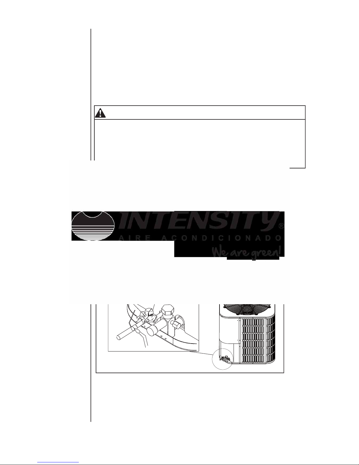
Good Refrigeration practices require the installation of a field supplied liquid line
drier, as shown in Fig.1.
Fig.1 Filter-Drier installation
LIQUID-LINE FILTER-DRIER
It will be more convenient to open
the Service valve after removing
the Underside Clapboard.
NOTE
LARGE SERVICE VALVE
SMALL SERVICE VALVE
FIELD SUPPLIED AND INSTALLED

5
DIMENSIONAL DATA
"H" in. [mm] "W" in. [mm]
"L" in. [mm]
Liquid in.
Suction in.
29-1/8[740] 29-1/8[740]
29-1/8[740] 29-1/8[740]
29-1/8[740] 29-1/8[740]
29-1/8[740] 29-1/8[740]
MODEL SIZE
Dimensions (Inches)
Refrigerant Connection
Service Valve Size
24-15/16[633]
3/8
3/8
3/8
3/8
3/4
3/4
7/8
7/8
24-15/16[633]
33-3/16[843]
33-3/16[843]
36
36
AC HP
24 24
48
48
60
60
FIG.2 DIMENSIONS
SUCTION LINE
CONNECTION
CONTROL WIRING
7/8” (22.2mm)
KNOCKOUT
1-11/32” (34.5mm)
LIQUID LINE
CONNECTION
SERVICE
FITTING
SERVICE
FITTING
POWER WIRING
SEE DETAIL A
DETAIL A
HOLE
1-3/32” (27.8mm)
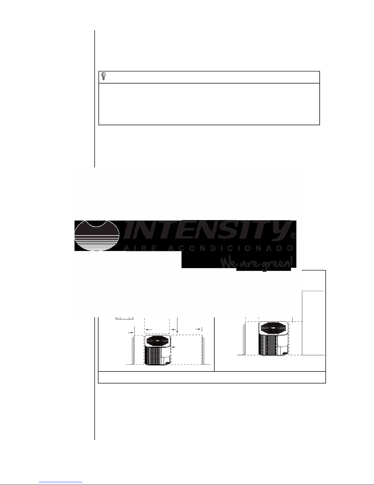
NOTE: GRILL APPEARANCE
MAY VARY.
NOTES: 1 AC: Air Condition er ; HP: Heat Pump;
AIR DISCHARGE: ALLOW 60”
MINIMUM CLEARANCE.
SERVICE ACCESS
ALLOW 24” CLEARANCE
AIR INLETS
LOUVERED PANELS
ALLOW 18”
MINIMUM
CLEARANCE
W
3.0 UNIT INSTALLATION
3.1 LOCATION
Before starting the installation, select and check the suitability of the location for both
the indoor and outdoor unit. Observe all limitations and clearance requirements. The
outdoor unit must have sufficient clearance for air entrance to the condenser coil, for air
discharge and for service access. See Fig.2
NOTE
For multiple unit installations, units must be spaced a minimum of 18 inches
apart. (Coil face to coil face.)
If the unit is to be installed on a hot sun exposed roof or a black-topped ground area, the
unit should be raised sufficiently above the roof or ground to avoid taking the accumulated layer of hot air into the outdoor unit.
Provide an adequate structural support.
WARNING
The outdoor unit should not be installed in an area where mud or ice could cause
personal injury or system damage.
Elevate the unit sufficiently to prevent any blockage of the air entrances by snow in
areas where there will be snow accumulation. Check the local weather bureau for the
expected snow accumulation in your area. Isolate the unit from rain gutters to avoid any
possible wash out of the foundation.
When installing units on a roof, the structure must be capable of supporting the total
weight of the unit, including a padded frame unit, rails, etc., which should be used to
minimize the transmission of sound or vibration into the conditioned space.
3.3 ROOF INSTALLATION
3.4 UNIT PLACEMENT
1. Provide a base in the pre-determined location.
2. Remove the shipping carton and inspect for possible damage.
3. Compressor tie-down nuts should remain tightened.
4. Position the unit on the base provided.
The unit may be installed at ground level on a solid base that will not shift or settle, causing strain on the refrigerant lines and possible leaks. Maintain the clearances shown in
Fig.2 and install the unit in a level position.
3.2 GROUND INSTALLATION
Normal operating sound levels may be objectionable if the unit is placed directly under
windows of certain rooms (bedrooms, study, etc.).
Top of unit discharge area must be unrestricted for at least 60 inches above the unit.
6
CAUTION
This system uses R410A refrigerant which operates at higher pressure than
R-22. No other refrigerant may be used in this system. Gauge sets, hoses,
refrigerant containers, and recovery system must be designed to handle
R410A. If you are unsure, consult the equipment manufacturer.
The outdoor unit must be connected to the indoor coil using field supplied refrigerant
grade copper tubing that is internally clean and dry. Units should be installed only with
the tubing sizes for approved system combinations. The refrigerant charge shown in
the nameplate is for standard size interconnecting liquid line lengths up to 15 feet.
7
NOTE
Using a larger than specified line size could result in oil return problems. Using a
too small line will result in loss of capacity and other problems caused by insufficient refrigerant flow. Slope horizontal suction lines at least 1" every 20 feet
toward the outdoor unit to facilitate proper oil return.
3.5 Unit Location Considerations
• Ensure the top discharge area is unrestricted for at least 5 feet above the unlt.
• Provide at least 3 feet clearance in front of the control box (access panels) and any other
side requiring service.
• Do not locate close to bedrooms as operational sounds may be objectionable.
• Avoid locations near windows and similar areas where condensation and freezing defrost
vapor can annoy a customer.
• Position the outdoor unit a minimum of 12" from any wall or surrounding shrubbery to
ensure adequate airflow.
• Outdoor unit location must be far enough away from any structure to prevent excess roof
runoff water or Icicles from ralling directly on the unit.
• Position the outdoor unit a minimum of 12" from any wall or surrounding shrubbery to
ensure adequate airflow.
• Outdoor unit location must be far enough away from any structure to prevent excess roof
runoff water or icides from ralling directly on the unit.
Avoid install
near bedrooms
Min 5 feet unrestricted
Min 3 feet
unrestricted
Min 12"
to wall
Min 20 inches
to shrubbery
Min 12" to
shrubbery
Access panel
1. suggested Locations for Best Reliability
Fig. 3 suggested Locations for Best Reliability

8
3.6 UNIT MOUNTING
2 . If elevating a unit on a flat roof , use 4”× 4”(or equivalent) stringers
positioned to distribute unit weight evenly and prevent noise and vibration (See Fig.3).
NOTE:Do not block drain openings shown in Fig.5.
3. If unit must be elevated because of anticipated snow fall, secure unit and
elevating stand such that unit and/or stand will not tip over or fall off.
If elevating the heat pump, either on a flat roof or on a slab, observe the following guidelines.
1. The base pan provided elevates the heat pump 2” above the base pad.
NOTE: To tie down unit, see 3.6.
BASE PAD
(CONCRETE OR
OTHER SUITABLE
MATERIAL)
Note: It is recommended that these precautions be taken for units being installed in areas
where snow accumulation and prolonged below-freezing temperatures occur.
• Units should be elevated 3-12 inches above the pad or rooftop, depending on local
weather. This additional height will allow drainage of snow and ice melted durIng defrost
cycle prior to its refreezlng. Ensure that drain holes in unit base pan are not obstructed,
preventing drainage of defrost water.
• If possible, avoid locations that are likely to accumulate snow drifts. if not possible, a snow
drift barrier should be installed around the unit to prevent a build-up of snow on the sides of
the unit.
Min 12"
Snow
barrier
3- 12" Elevation
Snow legs
pad
2. Cold Climate Considerations (Heat Pump Only)
Fig.4 Cold Climate Considerations (Heat Pump Only)
BASE PAN (BOTTOM
VIEW) DO NOT OBSTRUCT
DRAIN HOLES
(SHADED)
ELEVATION ABOVE
ANTICIPATED
SNOW IS NECESSARY
Fig.5 RECOMMENDED ELEVATED INSTALLATION
1. Install the lines with as few bends as possible. Care must be taken not to damage
the couplings or kink the tubing. Use clean hard drawn copper tubing where no
appreciable amount of bending around obstruction is necessary, if soft copper must
be used, care must be taken to avoid sharp bends which may cause a restriction.
2. The lines should be installed so that they will not obstruct service access to the coil,
air handling system or filter.
3.8 PRECAUTIONS DURING LINE INSTALLATION
9
3.7 FACTORY-PREFERRED TIE-DOWN METHOD
Step 3: Using field supplied L-shaped bracket to locate holes on concrete and drill pilot
holes which is at least 1/4” deeper than fastener being used.
IMPORTANT
Self drilling screws to base pan should not exceed 3/8” long to avoid damaging
coil.
Step 4: Using conventional practices to install brackets, tighten concrete fasteners and
self-tapping screws (See Fig.6).
NOTE
NOTE
: 1. One bracket for each side. For extra stability, 2 brackets for each side.
2. Do not over-tighten the concrete fastener to avoid weakening the concrete.
Step 1: Prior to installing clear pad of debris.
IMPORTANT
Then cement pad must meet local codes and must be the proper thickness to
accommodate fasteners.
Step 2: Center and level unit onto pad.
IMPORTANT NOTE:
These instructions are intended to provide a method to tie-down system to cement slab
as a securing procedure for high wind areas. It is recommended to check Local Codes
for tie-down methods and protocols.
REQUIRED PARTS LIST
SEE DETAIL B
#7 X 3/8” Self Tapping Screws
(Don’t Exceed 3/8” long)
1/4” 1-1/2” Hex Washer Head Concrete Screws
(3/16” Pilot Hole Needed. Pilot Hole Should Be1/4” Deeper
Than The Fastener Embedment)
Fig.6 PREFERRED TIE-DOWN METHOD
DETAIL B
Brackets:
2” width, 1/16” thickness,
height as required.
Available from distributor
or in market place.
The dimension see FIG.2

3. Care must also be taken to isolate the refrigerant lines to minimize noise transmis sion from the equipment to the structure.
4. The suction line must be insulated. Tape and suspend the refrigerant lines as shown.
DO NOT allow tube metal-to-metal contact. See Fig.7.
5. Use PVC piping as a conduit for all underground installations as shown in Fig.8.
Buried lines should be kept as short as possible to minimize the build up of liquid
refrigerant in the suction line during long periods of shutdown.
6. Pack a sealing material such as perma gum around refrigerant lines where they
penetrate a wall to reduce vibration and to retain some flexibility.
Insu la ted Liquid Line
Tape
Shee t Me tal Hanger
opt iona l
Sug gest ed
Incorrect
Fig.7 Tubing Hanger
Fig.8 Underground Installation
10
Insu la ted Suction Line
Fig.9
Typical Installation
TO
INDO OR
BLOW ER
TO
POWE R
SUPPLY
TO
COIL
WEATHERPR OOF
DISCONNECT
SWIT CH
Seal o pening(s) with
perm agum or equivalen t
24V co ntrol signal
NOTE :All outdoor wiri ng m ust be weather proo f
All outdoor unit and evaporator coil connections are copper-to-copper and should be
brazed with a phosphorous-copper alloy material such as Silfos-5 or equivalent. DO
NOT use soft solder. The outdoor units have reusable service valves on both the liquid
and suction connections. The total system refrigerant charge is retained within the
outdoor unit during shipping and installation. The reusable service valves are provided
to evacuate and charge per this instruction.
Serious service problems can be avoided by taking adequate precautions to assure an
internally clean and dry system.
3.9 PRECAUTIONS DURING BRAZING OF LINES
CAUTION
Dry nitrogen should always be supplied through the tubing while it is being
brazed, because the temperature required is high enough to cause oxidation
of the copper unless an inert atmosphere is provide. The flow of dry nitrogen
should continue until the joint has cooled. Always use a pressure regulator
and safety valve to insure that only low pressure dry nitrogen is introduced into
the tubing.Only a small flow is necessary to displace air and prevent oxidation.
Precautions should be taken to prevent heat damage to service valve by wrapping a wet
rag around it as shown in Fig.10. Also, protect all painted surfaces, insulation, during
brazing. After brazing cool joint with wet rag.
3.10 PRECAUTIONS DURING BRAZING SERVICE VALVE
The valve can be opened by removing the plunger cap and fully inserting a hex wrench
into the stem and backing out counter-clockwise until valve stem just touches the chamfered retaining wall.
11
1. Remove the cap and Schrader core from both the liquid and suction service valve
service ports at the outdoor unit. Connect Iow pressure nitrogen to the liquid line
service port.
Connect the refrigerant lines using the following procedure:
2. Braze the liquid line to the liquid valve at the outdoor unit. Be sure to wrap the valve
body with a wet rag. Allow the nitrogen to continue flowing. Refer to the Tabular Data
Sheet for proper liquid line sizing.
3. Carefully remove the rubber plugs from the evaporator liquid and suction connections
at the indoor coil.
Fig.10 Heat Protection
service valve
wet rag

4. Braze the liquid line to the evaporator liquid connection. Nitrogen should be flowing
through the evaporator coil.
5. Slide the plastic cap away from the suction connection at the indoor coil. Braze the
suction line to the evaporator suction connection. Refer to the Table 1 for proper
suction line sizing.
6. Protect the suction valve with a wet rag and braze the suction line connection to the
outdoor unit. The nitrogen flow should be exiting the system from the suction service
port connection. After this connection has cooled, remove the nitrogen source from
the liquid fitting service port.
7. Replace the Schrader core in the liquid and suction valves.
8. Leak test all refrigerant piping connections including the service port flare caps to be
sure they are leak tight. DO NOT OVER TIGHTEN (between 40 and 60 inch -lbs.
maximum).
9. Evacuate the suction line, evaporator, and the liquid line, to 350 microns or less.
Table 1: Recommended Liquid and Suction Tube Diameters (ln.)
MODEL
SIZE
LIQUID
SUCTION
Tube Diameter
Tube Diameter
24 3/8 3/4
36 3/8 3/4
48 3/8
60 3/8 7/8
12
7/8
10. Replace cap on service ports. Do not remove the flare caps from the service ports
except when necessary for servicing the system.
11. Release the refrigerant charge into the system. Open both the liquid and suction
valves by removing the plunger cap and with an hex wrench back out counter
-clockwise until valve stem just touches the chamfered retaining wall.
12. Replace plunger cap finger tight, then tighten an additional 1/12 turn (1/2 hex flat).
Cap must be replaced to prevent leaks.
WARNING
Never attempt to repair any brazed connections while the system is under pressure. Personal injury could result.
See "System Charge" section for checking and recording system charge.
4.0 INTERCONNECTING TUBING
4.1 SUCTION AND LIQUID LINES
Keep all lines sealed until connection is made.
Make connections at the indoor coil first.
Refer to Li ne Size Information in Ta bles 2 and 3 for correct size and multipliers to be
used to determine capacity for various suction line diameters and lengths of run. The
losses due to the lines being exposed to outdoor conditions are not included.
The factory refrigerant charge in the outdoor unit is sufficient for 15 feet of standard
size interconnecting liquid line. Calculate actual charge required with installed liquid
line size and length as below.
5/16” ± .4 oz. per foot
3/8” ± .6 oz . per foot
1/2” ± 1.2 oz . per foot

It will be necessary to evacuate the system to 350 microns or less. If a leak is
suspected, leak test with dry nitrogen to locate the leak. Repair the leak and test again.
To verify that the system has no leaks, simply close the valve to the vacuum pump
suction to isolate the pump and hold the system under vacuum. Watch the micron
gauge for a few minutes. If the micron gauge indicates a steady and continuous rise,
it's an indication of a leak. If the gauge shows a rise, then levels off after a few minutes
and remains fairly constant, its an indication that the system is leak free but still
contains moisture and may require further evacuation if the reading is above 350
microns.
5.0 EVACUATION
13
4.2 MAXIMUM LENGTH OF LINES
T h e maximum length of interconnecting line is 100 feet .
Always use the shortest length possible with a minimu m number of bends.
N
NOTE
: Excessively long refrigerant lines cause loss of equipment capacity.
4.3 VERTICAL LIFT
Keep the vertical lift to a minimum. Use the following guidelines when installing
the unit:
1. DO NOT exceed the vertical lift as indicated on Table 3.
2. It is recommended to use the smallest liquid line size permitted to minimize sys t
em charge which will maximize compressor reliability.
3. Table 3
may be used for sizing horizontal runs.
TABLE 2: SUCTION LINE LENGTH/SIZE VS CAPACITY MULTIPLIER(R410A)
2 Ton 3 Ton 4 Ton 5 Ton
3/4" O.D. 3/4" O.D. 7/8" O.D. 7/8" O.D.
5/8 Opt. 5/8 Opt. 3/4 Opt. 1 1/8 Opt.
3/4* Std. 3/4* Std. 7/8* Std. 7/8* Std.
Optional 1.00 1.00 1.00 1.00
Standard 1.00 1.00 1.00 0.99
Optional 0.97 0.97 0.98 0.99
Standard 0.98 0.99 0.98 0.98
Optional 0.94 0.94 0.95 0.98
Standard 0.95 0.97 0.97 0.94
Suction Line Connection Size
Model Size
Suction Line Run - Feet
NOTES:
* Standard size
Using suction line larger than shown in chart will result in poor oil return and is not recommended.
25'
50'
100'
Optional 0.90 0.90 0.92 0.97
Standard 0.92 0.96 0.96 0.90
150'
LINE SIZING

6.1 GENERAL INFORMATION & GROUNDING
Check the electrical supply to be sure that it meets the values specified on the unit
nameplate and wiring label.
Power wiring, control (Iow voltage) wiring, disconnect switches and over current
protection must be supplied by the installer. Wire size should be sized per requirements.
CAUTION
All field wiring must USE COPPER CONDUCTORS ONLY and be in accordance
with Local, National Fire, Safety & Electrical Codes. This unit must be grounded
with a separate ground wire in accordance with the above codes.
The complete connection diagram and schematic wiring label is located on the inside
surface of the unit service access panel and this instruction.
1. Install the proper size weatherproof disconnect switch outdoors and within sight of
the unit.
2. Remove the screws at the side of the corner panel. Slide corner panel down and
remove from unit. See Fig. 9.
3. Run power wiring from the disconnect switch to the unit.
4. Route wires from disconnect through power wiring opening provided and into the
unit control box.
5. Install the proper size time-delay fuses or circuit breaker, and make the power
supply connections.
6. Energize the crankcase heater if equipped to save time by preheating the compres sor oil while the remaining installation is completed.
6.2 FIELD CONNECTIONS POWER WIRING
6.0 ELECTRICAL CONNECTIONS
14
NOTE: When changing the motor, remove top cover first.
TABLE 3: LIQUID LINE SIZE (R410A)
25 50 75 100 125 150
1/4 23 N/A N/A N/A N/A N/A
5/16 25 36 29 23 16 9
3/8* 25 50 60 60 40 30
Rotary 3/8* 25 30 30 24
5/16 25 50 37 22 7 N/A
3/8* 25 50 60 60 40 30
3/8* 25 46 38 30 22 15
1/2 25 50 56 55 40 30
3/8* 25 50 56 44 32 20
1/2 25 50 60 60 40 30
Liquid Line Size
Outdoor unit above or below indoor coil
3/8"
3/8"
3 Ton
Total Equivalent Length - Feet
Model Size
Line Size
Connection And
Line Size
(Inch O.D.)
Maximum Vertical Separation - Feet
Line Size
Connection Size
(Inch O.D.)
Compressor
Type
Scroll
2 Ton 3/8"
NOTES:
* Standard line size
N/A Application not recommended.
Scroll
Scroll
Scroll
4 Ton
5 Ton
3/8"
N/A N/A

15
1/2” nut
5/16” nuts
Fig.12 COVER AND FAN
6.3 REMOVING THE TOP PANEL AND MOTOR
When motor requires changing follow the steps below:
Step 1: Go into electrical panel, disconnect motor power lines.
IMPORTANT NOTE
Disconnect main power to unit. Severe burns and electrical shock will occur if
you do not disconnect main power.
Step 2: Remove cover (be careful of motor wires)
Step 3: Be sure to place fan cover unit on the ground as indicated in Fig. 12
IMPROTANT NOTE
Do not place or lean fan blades on ground or against surface.
Step 4: Remove fan motor by removing 5/16” nuts from cover.
Step 5: Remove fan blade from motor by removing 1/2” nut and place fan on the ground.
Step 6: Reverse removal process to reinstall the fan and motor.
IMPROTANT NOTE
When connecting motor wires be sure to check motor direction.
Damage will occur to condenser unit
if you remove fan nuts prior to cover removal.
NOTE:
Fig.11 Typical Field Wiring
CORNER
PANEL
HIGH VOLTAGE WIRING
LOW VOLTAGE WIRING

16
7.2 CHARGING BY WEIGHT
7.3 FINAL LEAK TESTING
After the unit has been properly evacuated and charged, a halogen leak detector
should be used to detect leaks in the system. All piping within the condensing unit,
evaporator, and interconnec ting tubing should be checked for leaks. If a leak is
detected, the refrigerant should be recovered before repairing the leak. The Clean Air
Act prohibits releasing refrigerant into the atmosphere .
Charge for all systems should be checked against the Charging Chart inside the
access corner panel or Charging by weight.
IMPORTANT:Do not operate the compressor without charge in system. Additio n of
R - 410A will raise pressures (suction, liquid and discharge).
7.1 CHARGING BY LIQUID PRESSURE
7.0 CHECKING REFRIGERANT CHARGE
In order to properly charge the system, the following conditions must be met:
1) Outdoor temperature above 60°F.
2) Indoor temperature between 70°F to 100°F.
3) Installation must be complete with brazed joints and drier visually inspected.
4) The unit electrical installation must be checked and unit powered for one (I) hour if
crank case heater is used or five (5) minutes if no crankcase heater is used.
Follow these steps:
1. Run in Force cooling mode(click the FORCE button in cooling mode )at least 20
minutes.
2. Measure OUTDOOR AMBIENT TEMPERATURE within 6 inches of coil.
3. Measure SUCTION LINE PRESSURE AND TEMPERATURE.
4.According to the superheat of suction line, confirm that the TXV is working
properly(Usually the superheat is between 10 to 15). If not, it should be adjusted.
5. Find the TARGET LIQUID PRESSURE at the intersection between the SUCTION
LINE PRESSURE and the OUTDOOR AMBIENT TEMPERATURE, if falls between
rows or columns then estimate the TARGET LIQUID PRESSURE or SUCTION LINE
PRESSURE falls between rows or columns then estimate the TARGET LIQUID PRESSURE between the rows and columns.
5. Compare the measured LIQUID LINE PRESSURE to the TARGET LIQUID PRESSURE, add charge to raise the pressure or recover charge to lower it.
6. After running unit for 10 minutes if the SUCTION LINE PRESSURE changes, go
back to step 2 otherwise remove test equipment and cover the valves.
For a new installation,evacuation of interconnecting tubing and indoor coil is adequate;
otherwise,evacuate the entire system. The factory refrigerant charge in the outdoor
unit is sufficient for 15 feet of standard size interconnecting liquid line. Calculate
actual charge required with installed liquid line size and lengthplease see 4.1 of
instruction.
With an accurate scale (+/- 1 oz.) adjust charge difference between that shown on
the unit data plate and that calculated for the new system Installation. if the entire
system has been evacuated, add the total calculated charge.

17
charging: weigh-In Method
weigh-In Method can be used for the Initial installation, or anytime a system charge is being
replaced. weigh-In Method can also be used when power is not available to the equipment
site or operating conditions (indoor/Outdoor temperatures) are not In range to verify with
the subcooling charging method.
Note: The only mode aperoved for setting validating system charge Is using Charging
Mode-cooling. Charging Mode-cooling is a variable speed test mode found in the 950
comfort control Technician Menu. Outdoor Temperature must be between 55
O
F and
120OF with Indoor Temperature kept between 70OF and 80OF.
Table 17. Heat Pumps
D C A
Model
charge
adder for
Indoor Coil
charge
multiplier for
interconnecting
refrigerant tube
length
024 7 lb. 6 oz. 6 oz. 0.6 oz/f t
036 8 Ib. 3 oz. 8 oz. 0.6 oz/ft
037 9 lb. 8 oz. 12 oz. 0.6 oz/ft
048 9 lb. 13 oz. 13 oz. 0.6 oz/ft
049 10 lb. 12 oz. 15 oz. 0.6 oz/ft
060 11 lb. 14 oz. 1 lb., 2 oz. 0.6 oz/ft
Factory
Charge
B
Table 18. Air Conditioners
D C A
Model
charge
adder for
Indoor Coil
charge
multiplier for
interconnecting
refrigerant tube
length
024 7 lb. 6 oz. 6 oz. 0.6 oz/f t
036 7 Ib. 14 oz. 7 oz. 0.6 oz/ft
048 11 lb. 1 oz. 1 lb., 0 oz. 0.6 oz/ft
060 11 lb. 14 oz. 0.6 oz/ft
Factory
Charge
B
Table 19. New Installations — calculating charge using the weigh-In method
1. Measure in feet the distance between the
outdoor unit and the indoor unit and record on Line
1. Include the entire length of the line from the
servIce valve to the IDU.
2. Enter the charge multiplier from column D.
3. Muitply the total length of refrigerant tubing (Line
1) tImes the value on step 2. Record the result on
Line 3 of the worksheet.
4. Locate the outdoor equipment size in column A.
Record the value shown In column c of Table 16 for
Heat Pumps or Table 17 for Air conditioners.
5. Add the values from step 3 and step 4 and
record the resulting value. This Is the amount of
refrigerant to weigh-in prior to opening the service
valves.
New Installation weigh-In Method worksheet
1. Line Length (ft)
2. value from Column D x
3. Step1 x Step2 =
4. charge Adder (column C) +
5. Refrlgerant(Steps 3+4) =
Table 20. Sealed-System Repairs — calculating charge using the weigh-In method.
1. Meisure in feet the distance between the
outdoor unit and the indoor unit and record on
Line 1 Include the entire length of the line from the
service valve to the IDU.
2. Enter the charge multiplIer from cotumn D.
3. MultIply the total length of refhgerant tubing
(Line 1) times the value on Line 2. Record the
result on Line 3 of the worksheet.
4. Locate the outdoor equipment size in column A.
Record the value shown in column C of Table 16
for Heat Pumps or Table 17 for Air conditioners.
5. Record the value in column B to Line 5 of the
worksheet.
6. Add the values from step 3, step 4, and step 5
and record the resulting value on Line 6. ThIs is
the amount of refrigerant to weigh-in.
New Installation weigh-In Method worksheet
1. Line Length (ft)
2. value from ColumnD x
3. Step 1 x step 2 =
4. charge Adder (column C) +
5. Factory charge (column B) +
6. RefrIgerant (steps 3+4+5) =
1 lb., 0 oz.

18
8.0 SYSTEM OPERATION
1. Control logic description
2.Sensor description
This frequency conversion system adopts the exactly same control logic as that of
common fixed frequency unit. Start-up demand signal is sent by wired controller or
indoor unit and when outdoor unit receives the signal, it will start required mode according to demand. Start-up demand signal is the common 24V control signal.
Compressor operating frequency is controlled by outdoor unit completely.
To ensure stable and adequate power output, target control low pressure evaporating
temperature Te when cooling and target control high pressure condensing temperature
Tc when heating, control and adjust compressor PI according to control target demand.
Meanwhile, Te and Tc target demand has the function of self-study according to compressor operating frequency, start/stop times so that to adjust power output autonomously ensure to well satisfy power demand load.
It can choose the initial settings of Te and Tc according to dehumidification and high
capacity demands by manually adjusting the dial code as well so that to satisfy relative
demands.
A working T3 Sensor is required for:
Operating protection (high temp./low temp.)
Outdoor fan control(cooling)
Heat pump onlyDefrost Heat pump only
Ambient temp forecast Cooling only
A working T4 Sensor is required forHeat pump only:
Operating condition permission
Defrosting condition determination
Outdoor fan control(heating mode, Heat pump only)
A working T5 Sensor is required for:
Protection(high temp./low temp.)
Outside EEV control valve Heat pump only
A working Tf Sensor is required for:
Module temp. protection(high temp.)
A working Pressure Transducer Sensor is required for:
Operating frequency control
Outside EEV control valve Heat pump only
High pressure protection(heating mode, Heat pump only)
Low pressure protection(cooling mode)
2Defrost description
Outdoor defrost control needs to measure T4 ambient temp. sensor and T3 coil temp.
sensor. When difference value between the two sensors has satisfied some condition,
defrosting will begin. Meanwhile, Meanwhile when operating in the condition of a low
ambient temp.for a certain period or system high pressure side pressure is lower than a
certain value, the system will enter defrosting mode.

19
Refrigerant migration during the off cycle can result in a noisy start up. Add a crankcase
heater to minimize refrigeration migration, and to help eliminate any start up noise or
bearing “wash out”.
All heaters must be located on the lower half of the compressor shell. Its purpose is to
drive refrigerant from the compressor shell during long off cycles, thus preventing
damage to the compressor during start-up.
The crankcase heating start condition:
1.The crankcase heating start must meet two conditions:
A. Outdoor temperature 37.4° F.
B. Compressor stops working more than 3 hours.
2. Outdoor temperature 37.4° F and just connected to the power source.
The crankcase heating stop must meet condition:
Outdoor temperature 44.6° F or compressor start.
At initial start-up or after extended shutdown periods, make sure the heater is energized
for at least 12 hours before the compressor is started. (Disconnect switch on and wall
thermostat off.)
2Crankcase heating zone description
Dial code SW5
Defrosting quit
According to outdoor coil temp.T3 is up to 18and lasts for 1 min. Or defrosting time
is up to 8 min.
Defrosting control choice
Dial code SW5 can adjust and set the time that enters and quits defrosting
In general, adjust dial code to ON can enhance the ability of defrosting.
Manual defrosting:
The system must operate in heating mode.
Enter into this mode after 5 min when system starts(It is suggest that stably running for
30 min, then enter )
Press Force button and hold for at least 6s to enter into defrosting.
It is suggest that manual defrost time interval is 15min above.
Start if crankcase heating zone can satisfy one of the 3 conditions,
1. First time to power on
2. In process of defrosting
3Compressor stops running for 4h and the outdoor ambient temp. T4 once lower than
50.
Stop crankcase heating zone satisfy the following conditions
Air discharge temp. T5113
Defrosting enter
The following 3 situations were determined to enter into defrosting: Outdoor coil temp.
T31, and satisfy a certain correspondence of T4 ambient temp.
When operating time accumulates to a certain value. Because of ambient temp. T4
time settings are different, when T4<-5 , cumulative time is 4h, when T4-5 and T4
4 , the cumulative time is 2h to determine. When high pressure lasts low, the
situation that high pressure saturation temperature lower than 28 lasts for 20 min
determines to enter into defrosting.
Defrosting choice SW5-1 SW5-2 Remarks
ON
Oper ating time
shorten q0%
Def r os ti ng time is
becoming longer
OFF Normal Normal Default OFF
Remarks
En te r in t o t h e
situation
Quit situation
ON
OFF
1 2
8.1 COMPRESSOR CRANKCASE HEATER (CCH) (Heat pump only,optional)

20
8.3 PROTECTION FUNCTION INTRODUCTION (Heat pump only)
Sensor T3 (condenser pipe temperature) and T4 (outdoor ambient temperature)
When open-circuit, compressor, outdoor fan motor and reverse valve will be OFF.
T3149°F,compressor stop working ; T3140°F,compressor start working.
When T4 < 5 °F, compressor will stop.If the electrical heater kit is installed in the
indoor unit, the outdoor unit would provide a signal to drive up the heater.
When T4 > 10.4 °F, compressor will restart.
Discharge temperature protection (optional)
When discharge temp. > 275 °
F, the compressor will stop.
When discharge temp. < 194 °F, the compressor will restart.
High pressure protection (optional)
When high pressure > 638 PSIG, the compressor and outdoor fan motor will stop.
When high pressure < 464 PSIG, the compressor and outdoor fan motor will restart
(3 minutes delay necessary).
Low pressure protection
Low pressure < 21 PSIG, the compressor and outdoor fan motor will stop.
Low pressure > 44 PSIG, the compressor and outdoor fan motor will restart
(3 minutes delay necessary).
In stand-by status, the compressor will not start in low pressure protection.
Within 30 mins, if 4 protection cycles occurs.The system will be locked. It will
be restore after power cycle.
8.4 SENSORS
Start-up conditions of defrost mode:
When JUMP switch is set to “1”(See in Fig 11), the mode will start up in either of
the two following conditions:
1. Compressor operating, when T4 is > 28.4 °F and T3 is < 32 °F last for 40 minutes;
2. Compressor operating, when T4 is < 28.4 °F and T3 is < 32 °F last for 50 minutes.
When JUMP switch is set to “0”:
Compressor operating, when T3 is < 32 °F last for 30 minutes.
Shut-down conditions of defrost mode:
The mode will shut down in either of the two following conditions:
1. The defrosted time lasting for 10 minutes;
2. T3 is 77 °F.
8.2 REVERSING VALVE INTRODUCTION (Heat pump only)
Reversing valve energizes at the heating conditions, and cut off at the cooling condition.
When the compressor has been running more than 10 minutes in the heating mode,
holding down the FORCE button for at least 6 seconds, the systementers to the
defrost mode, and then exits the defrost mode normally by itself.
1. T3(condenser pipe temperature) and T4(outdoor ambient temperature, heat pump
only) see TABLE 4
2.T5(compressor discharge temperature) and Tf(IPM radiator fin temperature) see
TABLE 5.
3. Pressure sensor(cooling only) see TABLE 6, Pressure sensor(heat pump only) see
TABLE 7.

21
TABLE 4
TABLE 5
TEMP F TEMP C
RESISTANCE k VOLTS DC TEMP F TEMP C
RESISTANCE
k
VOLTS DC
-5 -20.6 600.134 4.93 140 60 13.643 3.14
0 -17.8 505.551 4.92 145 62.8 12.359 3.03
5 -15 427.463 4.91 150 65.6 11.214 2.91
10 -12.2 362.739 4.89 155 68.3 10.227 2.8
15 -9.4 308.891 4.87 160 71.1 9.308 2.68
20 -6.7 265.398 4.85 165 73.9 8.485 2.56
25 -3.9 227.481 4.83 170 76.7 7.746 2.45
30 -1.1 195.601 4.8 175 79.4 7.105 2.34
35 1.7 168.707 4.77 180 82.2 6.504 2.23
40 4.4 146.695 4.74 185 85 5.963 2.13
45 7.2 127.258 4.7 190 87.8 5.474 2.02
50 10 110.707 4.66 195 90.6 5.032 1.92
55 12.8 96.572 4.61 200 93.3 4.645 1.83
60 15.6 84.465 4.56 205 96.1 4.28 1.73
65 18.3 74.411 4.51 210 98.9 3.949 1.64
70 21.1 65.408 4.45 215 101.7 3.648 1.56
75 23.9 57.634 4.39 220 104.4 3.383 1.48
80 26.7 50.904 4.32 225 107.2 3.133 1.4
85 29.4 45.258 4.24 230 110 2.904 1.32
90 32.2 40.152 4.16 235 112.8 2.694 1.25
95 35 35.699 4.08 240 115.6 2.503 1.18
100 37.8 31.807 3.99 245 118.3 2.334 1.12
105 40.6 28.398 3.89 250 121.1 2.172 1.06
110 43.3 25.506 3.8 255 123.9 2.024 1
115 46.1 22.861 3.7 260 126.7 1.888 0.95
120 48.9 20.529 3.59 265 129.4 1.767 0.9
125 51.7 18.47 3.48 270 132.2 1.651 0.85
130 54.4 16.708 3.37 275 135 1.544 0.8
135 57.2 15.085 3.26 280 137.8 1.446 0.76
TEMP F TEMP C
RESISTANCE k VOLTS DC TEMP F TEMP C RESISTANCE k VOLTS DC
-5 -20.6 107.732 4.65 90 32.2 7.225 2.36
0 -17.8 93.535 4.6 95 35 6.401 2.21
5 -15 79.521 4.54 100 37.8 5.683 2.07
10 -12.2 67.795 4.47 105 40.6 5.057 1.93
15 -9.4 57.948 4.39 110 43.3 4.509 1.79
20 -6.7 49.652 4.3 115 46.1 4.028 1.67
25 -3.9 42.645 4.21 120 48.9 3.606 1.55
30 -1.1 36.710 4.1 125 51.7 3.233 1.43
40 4.4 27.386 3.86 130 54.4 2.902 1.32
45 7.2 23.732 3.73 135 57.2 2.610 1.22
50 10 20.610 3.59 140 60 2.350 1.13
55 12.8 17.939 3.45 145 62.8 2.119 1.04
60 15.6 15.648 3.3 150 65.6 1.914 0.96
65 18.3 13.681 3.15 155 68.3 1.731 0.88
70 21.1 11.987 2.99 160 71.1 1.574 0.82
75 23.9 10.527 2.83 165 73.9 1.416 0.75
80 26.7 9.265 2.67 170 76.7 1.276 0.68
85 29.4 8.172 2.52

22
TABLE 6
Te Pe
MPa
1 1.04 -22 0.27 47 2
2 1.07 -21 0.28 48 2.02
3 1.1 -20 0.3 49 2.05
4 1.11 -19.5 0.31 50 2.08
5 1.13 -19 0.31 51 2.11
6 1.14 -18.5 0.32 52 2.14
7 1.16 -18 0.33 53 2.16
8 1.17 -17.5 0.34 54 2.19
9 1.19 -17 0.35 55 2.22
10 1.21 -16.5 0.35 56 2.25
11 1.22 -16 0.36 57 2.28
12 1.24 -15.5 0.37 58 2.31
13 1.26 -15 0.38 59 2.34
14 1.27 -14.5 0.39 60 2.37
15 1.29 -14 0.4 61 2.4
16 1.31 -13.5 0.41 62 2.44
17 1.33 -13 0.41 63 2.47
18 1.35 -12.5 0.42 64 2.5
19 1.37 -12 0.43 65 2.53
20 1.38 -11.5 0.44 66 2.56
21 1.4 -11 0.45 67 2.6
22 1.42 -10.5 0.46 68 2.63
23 1.44 -10 0.47 69 2.67
24 1.46 -9.5 0.48 70 2.7
25 1.48 -9 0.49 71 2.74
26 1.5 -8.5 0.5 72 2.77
27 1.52 -8 0.51 73 2.81
28 1.54 -7.5 0.52 74 2.84
29 1.57 -7 0.53 75 2.88
30 1.59 -6.5 0.54 76 2.92
31 1.61 -6 0.55 77 2.95
32 1.63 -5.5 0.57 78 2.99
33 1.65 -5 0.58 79 3.03
34 1.68 -4.5 0.59 80 3.07
35 1.7 -4 0.6 81 3.1
36 1.72 -3.5 0.61 82 3.14
37 1.75 -3 0.62 83 3.18
38 1.77 -2.5 0.64 84 3.22
39 1.79 -2 0.65 85 3.26
40 1.82 -1.5 0.66 86 3.3
41 1.84 -1 0.67 87 3.35
42 1.87 -0.5 0.68 88 3.39
43 1.89 0 0.7 89 3.43
44 1.92 0.5 0.71 90 3.47
45 1.94 1 0.72 91 3.51
46 1.97 1.5 0.74 92 3.56
17 80.2376 74 8.4881 132 1.4937
18 76.6616 75 8.166 133 1.4551
19 73.2636 76 7.8945 134 1.4177
20 70.0337 77 7.6334 135 1.3813
21 66.9628 78 7.382 136 1.3461
22 64.0424 79 7.1401 137 1.3118
23 61.2643 80 6.9072 138 1.2786
24 58.6208 81 6.683 139 1.2463
25 56.1048 82 6.467 140 1.215
26 53.7095 83 6.259
For AC model: NSK-BD020I V=2*MPa+0.5
No. V No.
V

23
TABLE 7
Te/ Tc Pe/Pc Te/ Tc Pe/Pc Te/ Tc Pe/Pc
MPa
MPa
MPa
1 0.69 -30 0.17 56 1.37 2.5 0.76 111 2.54 30 1.78
2 0.7 -29 0.18 57 1.39 3 0.78 112 2.56 30.5 1.81
3 0.72 -28 0.19 58 1.4 3.5 0.79 113 2.59 31 1.83
4 0.73 -27 0.2 59 1.42 4 0.8 114 2.62 31.5 1.86
5 0.75 -26 0.22 60 1.43 4.5 0.82 115 2.65 32 1.88
6 0.76 -25 0.23 61 1.45 5 0.83 116 2.68 32.5 1.91
7 0.78 -24 0.24 62 1.47 5.5 0.85 117 2.71 33 1.93
8 0.79 -23 0.25 63 1.48 6 0.86 118 2.74 33.5 1.96
9 0.81 -22 0.27 64 1.5 6.5 0.88 119 2.77 34 1.98
10 0.82 -21 0.28 65 1.52 7 0.89 120 2.8 34.5 2.01
11 0.84 -20 0.3 66 1.53 7.5 0.91 121 2.83 35 2.04
12 0.85 -19.5 0.31 67 1.55 8 0.92 122 2.86 35.5 2.06
13 0.86 -19 0.31 68 1.57 8.5 0.94 123 2.89 36 2.09
14 0.87 -18.5 0.32 69 1.59 9 0.95 124 2.92 36.5 2.12
15 0.88 -18 0.33 70 1.61 9.5 0.97 125 2.95 37 2.15
16 0.89 -17.5 0.34 71 1.62 10 0.98 126 2.98 37.5 2.17
17 0.89 -17 0.35 72 1.64 10.5 1 127 3.02 38 2.2
18 0.9 -16.5 0.35 73 1.66 11 1.02 128 3.05 38.5 2.23
19 0.91 -16 0.36 74 1.68 11.5 1.03 129 3.08 39 2.26
20 0.92 -15.5 0.37 75 1.7 12 1.05 130 3.12 39.5 2.29
21 0.93 -15 0.38 76 1.72 12.5 1.07 131 3.15 40 2.32
22 0.94 -14.5 0.39 77 1.74 13 1.08 132 3.18 40.5 2.35
23 0.95 -14 0.4 78 1.76 13.5 1.1 133 3.22 41 2.38
24 0.96 -13.5 0.41 79 1.78 14 1.12 134 3.25 41.5 2.41
25 0.97 -13 0.41 80 1.8 14.5 1.14 135 3.29 42 2.44
26 0.98 -12.5 0.42 81 1.82 15 1.15 136 3.32 42.5 2.47
27 0.99 -12 0.43 82 1.84 15.5 1.17 137 3.36 43 2.5
28 1.01 -11.5 0.44 83 1.86 16 1.19 138 3.39 43.5 2.53
29 1.02 -11 0.45 84 1.88 16.5 1.21 139 3.43 44 2.56
30 1.03 -10.5 0.46 85 1.9 17 1.23 140 3.46 44.5 2.59
31 1.04 -10 0.47 86 1.92 17.5 1.24 141 3.5 45 2.62
32 1.05 -9.5 0.48 87 1.94 18 1.26 142 3.54 45.5 2.66
33 1.06 -9 0.49 88 1.97 18.5 1.28 143 3.57 46 2.69
34 1.07 -8.5 0.5 89 1.99 19 1.3 144 3.61 46.5 2.72
35 1.09 -8 0.51 90 2.01 19.5 1.32 145 3.65 47 2.76
36 1.1 -7.5 0.52 91 2.03 20 1.34 146 3.69 47.5 2.79
37 1.11 -7 0.53 92 2.06 20.5 1.36 147 3.73 48 2.82
38 1.12 -6.5 0.54 93 2.08 21 1.38 148 3.77 48.5 2.86
39 1.13 -6 0.55 94 2.1 21.5 1.4 149 3.8 49 2.89
40 1.15 -5.5 0.57 95 2.13 22 1.42 150 3.84 49.5 2.93
41 1.16 -5 0.58 96 2.15 22.5 1.44 151 3.88 50 2.96
42 1.17 -4.5 0.59 97 2.17 23 1.46 152 3.93 50.5 3
43 1.19 -4 0.6 98 2.2 23.5 1.49 153 3.97 51 3.03
44 1.2 -3.5 0.61 99 2.22 24 1.51 154 4.01 51.5 3.07
45 1.21 -3 0.62 100 2.25 24.5 1.53 155 4.05 52 3.1
46 1.23 -2.5 0.64 101 2.27 25 1.55 156 4.09 52.5 3.14
47 1.24 -2 0.65 102 2.3 25.5 1.57 157 4.13 53 3.18
48 1.25 -1.5 0.66 103 2.32 26 1.6 158 4.18 53.5 3.22
49 1.27 -1 0.67 104 2.35 26.5 1.62 159 4.22 54 3.25
50 1.28 -0.5 0.68 105 2.38 27 1.64 160 4.26 54.5 3.29
51 1.3 0 0.7 106 2.4 27.5 1.66 161 4.31 55 3.33
52 1.31 0.5 0.71 107 2.43 28 1.69 162 4.35 55.5 3.37
53 1.33 1 0.72 108 2.45 28.5 1.71 163 4.39 56 3.41
54 1.34 1.5 0.74 109 2.48 29 1.73 164 4.44 56.5 3.45
55 1.36 2 0.75 110 2.51 29.5 1.76 165 4.48 57 3.49
For HP model: NSK-BD035I V=(8/7)*MPa+0.5
No.
V
No.
V
No.
V

24
krameR noitinifed noitcetorp ro rorrE tnetnoc yalpsiD
E4 Temp. sensor error
E5 Voltage protection(overvoltage and undervoltage)
Self-recovery for the first v oltage protection, second voltage
protection needs to be powered on and then recover.
E6 DC motor error
niaga no nehw revoceR nim 01 ni snoitcetorp 6E 2 bE
E7 Air discharge sensor T5 loosely-inserted error
H0 Main control chip and comm. Chip comm. error
niaga no gnirewop nehw revoceR nim 021 ni snoitcetorp )3P( 3 3H
H4 3 (P6) protec tions in 60 min
Recover when powering on again
H5 5 (P2) protec tions in 100 min
Recover when powering on again
H6 3 (P4) protec tions in 100 min
Recover when powering on again
H8 Pressure sensor error
Hb Heating high pressure protection
HH PH standby in 200 min.
Recover when powering on again
P0 Module radiator tem p. Tf protection
P1 High pressure protection
P2 Low pressure protection
P3 f requency-conversion over-current protection
P4 Air discharge overtemperature protection
Cooling high pressure protection
(T3 pipe high temp.)
P6 Compressor instant over-cu
rrent protection
PH Compressor liquid –return protection
.sutats lamron ot revocer lliw ti ,nim 2 retfA noitcetorp noohpyt naf CD 8P
C3 T3 sensor loosely-inserted error
CE 5 P1 protections in 150min
Recover when powering on again
F1 High pressure protection switch error
F3 5 P5 protec tions in 180min
Recover when powering on again
F4 3 P0 protec tions in 120min
Recover when powering on again
5 Hb protections in 180min
Recover when powering on again
Frequency limited/status definition
D T5 high temp. protection frequency limit
P Compression ratio protection frequenc y limit
F Module temp. protection frequency lim
it
C Current protection frequency limit
U V oltage protection frequency limit
H Condensing pressure protection frequency limit
A Oil return
dF Defrost
T3 high temp. protection frequenc y limit L
F5
P5
8.5 Error code table
powering
twice

25
krameR elpmaxE tnetnoc kcehc tnioP .oN
TR+ledoM 3C yticapac tinu roodtuO 0
2 edom tinu roodtuO 1
0 standby,2
cooling
3heating
2 Outdoor unit set frequenc y
eulav lautcA eerged gninepo VXE 3
4 T3 tube temp.
5 T4 ambient temp.
6 T5 air discharge temp.
7 Reserved
8 Te low pressure temp.(air return saturation)
9 Tc high pressure temp.(Air dischage saturation)
10 Tf module temp.
Actual value
*10
Actual value
*10
13 Air discharge s uperheat
14 Reserved
15 Reserved
16 Frequency c onversion current
17 Voltage value
18 Air speed
19 Reserved
20 Reserved
21 Reserved
Spit oil quantity
Actual value
/10
23 The last time error code
24 Software version
25 Remark“--”
22
Pc high pressure (air discharge pressure) 12
Pe low pressure (air return pressure) 11
1Shift to display content of data code pipe when pressing point check key shortly(check key).
Display the next set of data when press the key once. The display content is accordance with the
sequence.
2There’re 3 digits for LED. The first digit is sequence(only display units digit, recycling display), the
second and third digits are values. For example, the 8th item is operating low pressure saturation
temperature. The 11th item is operating low pressure. For detailed meanings, please refer to the point
check table.3. After staying for 20s, it will recover to the normal status display
4For normal status display, the last 2 digits of nixie tube will display ambient temp when the unit is in
standby status(the first nixie tube has no display). When operating, last 2 digits of nixie tube will display
operating frequency.(If there’s system protection, the first digit of nixie tube will display status code,
details for code meaning, please refer to the error code table )
8.6 Parameter point check table

10.0 WIRING DIAGRAM
26
9.0 WARRANTY
9.1 MAINTENANCE
1. Dirt should not be allowed to accumulate on the indoor or outdoor coils or other parts
in the air circuit. Clean as often as necessary to keep the unit clean. Use a brush,
vacuum cleaner attachment, or other suitable means.
2.
The outdoor fan motor is permanently lubricated and does not require periodic oiling.
3. Refer to the furnace or air handler instructions for filter and blower motor maintenance.
4. The indoor coil and drain pan should be inspected and cleaned regularly to assure
proper drainage.
Assist owner with processing Warranty cards and/or online registration.
CAUTION
Thes e un its must be wired and insta ll ed in accordance with all N at ional and
Loca l Sa fety Codes.
CAUTION
It is unlawful to knowingly vent, release or discharge refrigerant into the open air
during repair, service, maintenance or the final disposal of this unit. When the
system is functioning properly and the owner has been fully instructed, secure the
owner’s approval.
10.1 CONTROL WIRING FOR UNITS
TH ERMOSTAT
C
C
R E
D
D
YE LLO
W
W
GREE
N
N
Y
Y
R
R
G
G
INDOOR UNIT
INDOOR UNIT
OUTDOOR UNIT
OUTDOOR UNIT
G
G
C
C
Y
Y
B
LACK
LACK
R
R
C
C
Fig.12 Control Wiring for A/C Systems.
B
LACK
LACK

27
Fig.1 4 Outdo or Unit W iring D ia gra m fo r Syste ms
(2 08/23 0V 1P 60H z) (24/ 36 K).
THERMOSTAT
C
RED
GREEN
INDOOR UNIT
OUTDOOR UNIT
Y
R
G
R Y
YELLOW
BLACK
BLACK
G
C
C
B
R
B
RED
BLUE
Fig.13 Control Wiring for H/P Systems.
W2
D
PURPLE
w1
WHITE
F T
5 T
F T
L - C F P
1 L
2 L
N O
4 T
C P H
V E E
Y W C
B
S P
1 V S
U
V
W
P
V
W
U
V
W
U
2 P
4 P
H C C
N W O R B
W O L L E Y
G / Y
H
L
M O C
: G N I N R A W
Y L T N E M N A M R E P E B T S U M T E N I B A C
M R O F N O C O T G N I R I W L L A D N A D E D N U O G
L A C O L D N A , C . L . C , C . E . C , C . E . N , C . E . I O T
T N E M E C A L P E R E L B A C I L P P A S A S E D O C
D N A E G U A G E M A S E H T E B T S U M E R I W
E R I W L A N I G I R O S A E P Y T N O I T A L U S N I
Y L N O S R O T C U D N O C R E P P O C E S U
D D I I S S P
P
4
4
4
4
1 - 5 W S
2 - 5 W S
F F O
N O
F F O
F F O
N O
S 0 6 : g n i t s o r f e d d n e e h t f o y a l e D e m i T
g n i t s o r f e d l a m r o N
g n i t s o r f e d e h t o t n i e c n a v d A
P M O C
P A C
E C N A T I C A P A C
H C C
E V L A V Y A W - 4
V E E
E V L A V E V I S N A P X E C I R T C E L E
C P H
H C T I W S E R U S S E R P H G I H
3 T
5 T
4 T
R O S N E S E R U T A R E P M E T R E S N E D N O C
R O S N E S E R U T A R E P M E T T N E I B M A R O O D T U O
G N I T A E H E S A C K N A R C
R O S N E S E R U T A R E P M E T E G R A H C S I D . P M O C
1 V S
L - C F P
E C N A T C U D N I C F P
S P
R O S N E S E R U S S E R P
L E D O M P H R O F Y L N O
L E D O M P H R O F Y L N O : 1 J
L E D O M P H R O F Y L N O W D N A B
L E D O M P H R O F Y L N O
W O L L E Y W O L L E Y
K C A L B
E U L B
E G N A R O
E G N A R O
E G N A R O
E G N A R O
N
N W O R B
R O S N E S . P M E T R O T A I D A R
R O S S E R P M O C
3
3
3
3
+
-
2 - 4 W S
3 - 4 W S
d e s u t o N
4 - 4 W S
F F O
N O
g n i t a e h / g n i l o o c y l l a m r o N
F F O
N O
g n i t a e h / g n i l o o c d e t a r e l e c c A
e l b a s i d t u p t u o y t i c a p a c e v i t p a d A
t u p t u o y t i c a p a c e v i t p a d A
1 - 4 W S
d e s u t o N
4 H
5 H
6 H
s e t u n i m 0 0 1 n i n o i t c e t o r p ) 4 P ( s e m i t 3
C H
t l u a f r o s n e s e r u t a r e p m e t l a t n e m n o r i v n E
b H
g n i t a e H n i n o i t c e t o r p e r u s s e r p h g i h
H H
s e t u n i m 0 8 1 n i s e m i t 3 g n i n n u r t e W
5 E
7 E
6 E
n o i t c e t o r p e g a t l o V
d e v r e s e R
t l u a f d e t a e s t o n s i r o s n e s s a g t s u a h x e e h T
4 E
E D O C
0 H
p i h c l o r t n o c n i a m n i t l u a f n o i t a c i n u m m o C
s e t u n i m 0 6 n i n o i t c e t o r p ) 6 P ( s e m i t 3
s e t u n i m 0 0 1 n i n o i t c e t o r p ) 2 P ( s e m i t 3
6 P
H P
E C
n o i t c e t o r p e r u s s e r p h g i H
3 C
t l u a f d e t a e s t o n s i r o s n e s 3 T e h T
4 F
s e t u n i m 0 8 1 n i n o i t c e t o r p . p m e t h g i h 3 T s e m i t 3
2 P
4 P
3 P
n o i t c e t o r P e r u s s e r p w o L
n o i t c e t o r p t n e r r u c r e v O
s e t u n i m 0 0 1 n i n o i t c e t o r p ) 1 P ( s e m i t 3
t l u a f d e t a e s t o n s i r o s n e s s a g t s u a h x e e h T
1 P
0 P
n o i t c e t o r P . p m o c e h t f o . p m e t t s u a h x e e h T
5 P
n o i t c e t o r p . p m e t e b u t e h T h g i H
n o i t c e t o r p e l u d o m M P I e h T
y b d n a t s g n i n n u r t e W
3 F
n o i t p i r c s e d t l u a F
8 H
t l u a f r o s n e s e r u s s e r P
9 H
s e t u n i m 0 6 n i n o i t c e t o r p ) 9 P ( s e m i t 3
d e v r e s e R
s e t u n i m 0 2 1 n i n o i t c e t o r p ) 0 P ( s e m i t 3
S 0 2 1 : g n i t s o r f e d d n e e h t f o y a l e D e m i T
N O
F F O
D E L N E E R G
t l u a f d r a o b l o r t n o c c i r t c e l E
y b d n a t S
9
9
8
8
4
4
t l u a f n o i t a c i n u m m o C
n o i t c e t o r p e l u d o m M P I e h T
n o i t c e t o r p e g a t l o v c d w o L
r o r r e e s a h p r o s s e r p m o C
t l u a f l o r t n o c M P I e h T
H A S L F D E L D E R
0
0
n o i t a r e p o r o s s e r p m o C
O O N
N
O O F F F
F
8 4 7 0 9 5 5 7 0 2 0 2
1 J
F F O
N O
F F O
N O
y l n o g n i l o o C
2 J
m e t s y s P H
n o t 3
n o t 5 . 2
S G N I T T E S Y R O T C A F
3 T

28
Fig.1 5 Outdo or Unit W iring D ia gra m fo r Syste ms
(2 08/23 0V 1P 60H z) (48/ 60 K).
TF
T5
TF
L1
L2
T4
HPC
EEV
PS
CCH
WARNING: CABINET MU ST BE PERMANMENTLY
GOUNDED AND ALL WI RING TO CONFORM TO
I.E.C,N.E.C, C.E.C,C.L.C,AND LOCAL C ODES AS APPLIC ABLE
REPLACEMENT WIRE MUST BE THE SAME GAUGE AND
INSULATION TYP E AS ORIGINAL WIRE
USE C OPPE R CON DUCTORS ONLY
COMP
CAP
CAPAC ITAN CE
CC H
4-WAY VALVE
EEV
ELECTRIC EXPANSI VE VALVE
HP C
HIGH PRES SURE SWITCH
T3
T5
T4
CONDENSER TEMPERATURE SENSOR
CRANKCASE HEATING
COMP. DISCHARGE TEMPERATURE SENSO R
SV1
PFC-L
PFC INDUCTANCE
PS
PRES SUR E SEN SOR
RADIAT OR TEMP. SENSO R
COM PR ESSOR
+
-
+
-
DB 1
H4
H5
H6
3 tim es (P4 ) prote ction in 10 0 minutes
F1
Temperature sensor fault(T3 T4 T5 TF)
Hb
High pressure protection in Heating
HH
Wet ru nni ng 2 times in 200 minu tes
E5
Eb
E6
Voltage protection
DC fan motor fault
The exhaust gas sensor(T5) is not seated fault
E4
CODE
H0
Communication fault in main control chip
3 t i m e s (P6) pr otection in 60 minutes
5 t i m e s (P2) pr ote ctio n in 100 min ute s
P6
PH
P8
Typhoon pro tec tion of t he fan moto r
CE
High pressure protection
C3
The T3 sensor is not seated fault
F5
P2
P4
P3
Low pressure Pro tection
5 times (P1) protection in 150 minutes
P1
P0
The exhaust temp. Of the comp. Protection
(T5)
P5
H i gh The tub e temp. (T3) pr otection
Th e IPM modu le p rotectio n
Wet running standby
F3
Fault descrip tion
H8
Pre ssure s ensor(PS) faul t
2 times (E6) protection in 10 minutes
Hig h p
ressure swi tch (HPC) fault
5 ti mes (Hb) protectio n in 180 min utes
Com pr es so r ov e r current protection
5 t im es ( P5 ) pro tection in 180 mi nute s
F4
3 tim es (P 0) protectio n in 120 minutes
The module radiator temperature (TF)protection
ON
SW5-1
SW5-2
OFF
ON
OFF
OFF
ON
Time D elay of the end defrosting:60S
Normal defrosting
A dva nce into t he d efrosting
SW4-2
SW4-3
Not used
SW4-4
OFF
ON
Normally cooling/heating
OFF
ON
A cce lerated cooling/heating
Adaptive cap acit y output di sabl e
A daptive cap acity out pu t en abl e
SW4-1
Not used
Time D elay of the end defrosting:120S
ON
OFF
GREEN LED
Electric control board fault
St an dby
The IPM mo dul e protectio n
Low dc vol ta ge p rotection
Compressor phase error
The IPM control fault
RED LED FLSAH
Compressor operation
Co mmuni cation f au lt
T3
AM B IE NT TEMPERA TU R E S ENSO R( FOR HP SYS TEM)
10 K RESISTANCE ( FOR COOLING ONLY SYSTEM)
COMP
202075890714
E7

29
Function description for the corresponding position
6
5
7
8
9
10
11
12
13
17
19
20
21
22
23
1
2
3
14
4
15
16
18
24
tnetnoC .oN tnetnoC .oN
trop gnitcennoc rellortnoc .pmeT 31 lanimret gniriw rosserpmoC 1
2 Reactor wiring terminal(connect a reactor between 2 and 3 ) 14 Function dial code SW4
3 Reactor wiring terminal(connect a reactor between 2 and 3 ) 15 Spot check button
nottub noitarepo decroF 61 5WSedoc laid noitcnuf gnitsorfeD 4
devreseR 71 trop rosnes erusserP 5
yalpsid ebut eixiN 81 trop rosnes.pmet egrahcsid riA 6
trop lortnoc naF 91 )ylno PH(trop rosnes.pmet roodtuO 7
lanimret lortnoc enoz gnitaeh esacknarC 02 trop rosnes.pmet resnednoC 8
eriw trohS 12 trop rosnes.pmet rotaidaR 9
lanimret gnitcennoc ylppus rewoP 22 trop hctiws erusserp hgiH 01
lanimret gnitcennoc ylppus rewoP 32 )ylno PH(trop evird VXE 11
pmal rotacidnI 42 trop evlav yaw-4 21

30
REFRIGERANT CHARGE FOR AC SYSTEM
55 60 65 70 75 80 85 90 95 100 105 110 115
177
173
169
165
161
157
153
149
145
141
137
133
129
125
121
117
113
109
Suct ion Pressure at
Large Serv ice Valve(psig)
Cooling Mode
18 SEER R410A AC Charge Chart 2 TON
Outdoor Ambient Temperature(°F)
Lipuid Pr essure at Small Service Valve(psig)
55 60 65 70 75 80 85 90 95 100 105 110 115
177
173
169
165
161
157
153
149
145
141
137
133
129
125
121
117
113
109
Suct ion Pressure at
Large Serv ice Valve(psig)
Cooling Mode
18 SEER R410A AC Charge Chart 3 TON
Outdoor Ambient Temperature(°F)
Lipuid Pr essure at Small Service Valve(psig)
55 60 65 70 75 80 85 90 95 100 105 110 115
177
173
169
165
161
157
153
149
145
141
137
133
129
125
121
117
113
109
Suct ion Pressure at
Large Serv ice Valve(psig)
Cooling Mode
18 SEER R410A AC Charge Chart 5 TON
Outdoor Ambient Temperature(°F)
Lipuid Pr essure at Small Service Valve(psig)
55 60 65 70 75 80 85 90 95 100 105 110 115
177
173
169
165
161
157
153
149
145
141
137
133
129
125
121
117
113
109
Suct ion Pressure at
Large Serv ice Valve(psig)
Cooling Mode
18 SEER R410A AC Charge Chart 4 TON
Outdoor Ambient Temperature(°F)
Lipuid Pr essure at Small Service Valve(psig)
307 330 353 376 403 430 457 484
286 306 329 352 375 402 429 456 483
266 285 305 328 351 374 401 428 455 482
245 265 284 304 327 350 372 400 427 454 481
224 244 264 283 303 326 349 371 399 426 453 480
203 223 243 263 282 302 325 347 370 398 425 452 479
202 222 242 262 281 301 324 346 369 396 423 450 478
201 221 241 261 280 300 323 345 368 395 422 449 477
200 220 240 260 279 299 322 344 367 394 421 448 476
199 219 239 259 278 298 321 343 366 393 420 447 475
198 218 238 258 277 297 320 342 365 392 419 446 473
197 217 237 257 276 296 319 341 364 391 418 445 472
196 216 236 256 275 295 318 340 363 390 417 444 471
195 215 235 255 274 294 316 339 361 389 416 443 470
194 214 234 254 273 293 315 338 360 388 415 442 469
193 213 233 253 272 292 314 337 359 387 414 441 468
192 212 232 252 271 291 313 336 358 385 412 439 467
191 211 231 251 270 290 312 335 357 384 411 438 466
312 334 357 379 404 430 456 482
291 311 333 355 378 403 429 455 481
271 290 310 332 354 376 402 428 454 480
250 269 289 309 331 353 375 401 427 453 478
229 249 268 288 307 329 352 374 399 425 451 477
209 228 247 267 286 306 328 350 373 398 424 450 476
206 226 246 266 285 305 327 349 371 397 423 449 474
207 226 245 264 284 304 326 348 370 396 422 448 473
205 224 244 263 283 302 324 347 369 394 420 446 472
204 223 242 262 281 301 323 345 367 393 419 445 471
201 221 241 261 280 300 322 344 366 392 418 444 469
202 221 240 259 279 298 321 343 365 390 416 442 468
200 219 239 258 278 297 319 341 364 389 415 441 467
199 218 237 257 276 296 318 340 362 388 414 440 465
196 216 236 256 275 295 317 339 361 386 412 438 464
195 215 235 254 274 293 315 337 360 385 411 437 463
195 214 233 253 272 292 314 336 358 384 410 436 461
192 212 232 252 271 291 313 335 357 383 409 435 460
304 327 349 372 398 424 450 475
284 303 326 348 371 396 422 448 474
264 283 302 325 347 370 395 421 447 473
243 263 282 301 323 346 368 394 420 446 472
223 242 261 281 300 322 345 367 393 419 445 471
203 222 241 260 280 299 321 344 366 392 418 444 470
202 221 240 259 279 298 320 343 365 391 417 443 469
201 220 239 258 278 297 319 342 364 390 416 442 468
198 218 238 257 277 296 318 341 363 389 415 441 467
197 217 237 256 276 295 317 340 362 388 414 440 466
197 216 235 255 274 294 316 338 361 387 413 439 464
196 215 234 254 273 293 315 337 360 385 411 437 463
193 213 233 253 272 292 314 336 359 384 410 436 462
192 212 232 252 271 291 313 335 357 383 409 435 461
191 211 231 251 270 290 312 334 356 382 408 434 460
190 210 230 250 269 289 311 333 355 381 407 433 459
189 209 229 249 268 288 310 332 354 380 406 432 458
188 208 228 247 267 287 309 331 353 379 405 431 457
303 325 347 369 394 418 443 468
284 302 324 346 368 393 418 442 467
264 283 301 323 345 368 392 417 441 466
244 263 282 300 322 345 367 391 416 440 465
224 243 262 281 300 322 344 366 390 415 440 464
204 223 242 261 280 299 321 343 365 389 414 439 463
203 222 241 260 279 298 320 342 364 388 413 438 462
200 220 240 259 278 297 319 341 363 388 412 437 461
199 219 239 258 277 296 318 340 362 387 411 436 460
199 218 238 257 276 295 317 339 361 386 410 435 460
198 217 236 256 275 294 316 338 360 385 409 434 459
197 216 235 255 274 293 315 337 359 384 409 433 458
194 214 234 254 273 292 314 336 359 383 408 432 457
193 213 233 253 272 291 313 336 358 382 407 431 456
192 212 232 252 271 291 313 335 357 381 406 431 455
193 212 231 250 270 290 312 334 356 380 405 430 454
192 211 230 249 269 289 311 333 355 379 404 429 453
189 209 229 248 268 288 310 332 354 379 403 428 452

31
REFRIGERANT CHARGE FOR HP SYSTEM
55 60 65 70 75 80 85 90 95 100 105 110 115
177
173
169
165
161
157
153
149
145
141
137
133
129
125
121
117
113
109
Coo lin g Mo de
18 SEER R410A HP Charge Chart 2 TON (cooling mode)
Outdoor Ambient Temperature(°F)
Lipuid Pr essure at Small Service Valve(psig)
Suct ion Pressure at
Large Serv ice Valve(psig)
55 60 65 70 75 80 85 90 95 100 105 110 115
177
173
169
165
161
157
153
149
145
141
137
133
129
125
121
117
113
109
Coo lin g Mo de
18 SEER R410A HP Charge Chart 3 TON (cooling mode)
Outdoor Ambient Temperature(°F)
Lipuid Pr essure at Small Service Valve(psig)
Suct ion Pressure at
Large Serv ice Valve(psig)
55 60 65 70 75 80 85 90 95 100 105 110 115
177 322 346 371 395 424 452 480 508
173 301 320 344 369 393 422 450 478 506
169 279 299 318 342 367 391 420 448 476 504
165 258 277 297 316 340 365 389 418 446 474 502
161 237 256 275 295 314 338 363 387 416 444 472 500
157 216 235 254 273 293 312 336 361 385 414 442 470 498
153 214 233 252 271 291 310 334 359 383 412 440 468 496
149 212 231 250 269 289 308 332 357 381 410 438 466 494
145 210 229 248 267 287 306 330 355 379 408 436 464 492
141 208 227 246 265 285 304 328 353 377 406 434 462 490
137 206 225 244 263 283 302 326 351 375 404 432 460 488
133 204 223 242 261 281 300 324 349 373 402 430 458 486
129 202 221 240 259 279 298 322 347 371 400 428 456 484
125 200 219 238 257 277 296 320 345 369 398 426 454 482
121 198 217 236 255 275 294 318 343 367 396 424 452 480
117 196 215 234 253 273 292 316 341 365 394 422 450 478
113 194 213 232 251 271 290 314 339 363 392 420 448 476
109 192 211 230 249 269 288 312 337 361 390 418 446 474
Coo lin g Mo de
18 SEER R410A HP Charge Chart 4TON (c ooling mode)
Outdoor Ambient Temperature(°F)
Lipuid Pr essure at Small Service Valve(psig)
Suct ion Pressure at
Large Serv ice Valve(psig)
55 60 65 70 75 80 85 90 95 100 105 110 115
177
173
169
165
161
157
153
149
145
141
137
133
129
125
121
117
113
109
Coo lin g Mo de
18 SEER R410A HP Charge Chart 5 TON (cooling mode)
Outdoor Ambient Temperature(°F)
Lipuid Pr essure at Small Service Valve(psig)
Suct ion Pressure at
Large Serv ice Valve(psig)
315 338 361 384 411 437 463 489
294 313 336 359 382 409 435 461 487
274 292 311 334 357 380 407 433 459 485
253 272 290 309 332 355 378 405 431 457 483
232 251 270 288 307 330 353 376 403 429 455 481
211 230 249 268 286 305 328 351 374 401 427 453 479
209 228 247 266 284 303 326 349 372 399 425 451 477
207 226 245 264 282 301 324 347 370 397 423 449 475
205 224 243 262 280 299 322 345 368 395 421 447 473
203 222 241 260 278 297 320 343 366 393 419 445 471
201 220 239 258 276 295 318 341 364 391 417 443 469
199 218 237 256 274 293 316 339 362 389 415 441 467
197 216 235 254 272 291 314 337 360 387 413 439 465
195 214 233 252 270 289 312 335 358 385 411 437 463
193 212 231 250 268 287 310 333 356 383 409 435 461
191 210 229 248 266 285 308 331 354 381 407 433 459
189 208 227 246 264 283 306 329 352 379 405 431 457
187 206 225 244 262 281 304 327 350 377 403 429 455
308 331 354 378 405 432 459 486
287 307 330 353 377 404 431 458 485
266 286 306 329 352 376 403 430 457 484
245 265 285 305 328 351 374 402 429 456 483
224 244 264 284 304 327 350 373 401 428 455 482
203 223 243 263 283 303 326 349 372 400 427 454 481
202 222 242 262 282 302 325 348 371 398 425 452 480
201 221 241 261 281 301 324 347 370 397 424 451 479
200 220 240 260 280 300 323 346 369 396 423 450 478
199 219 239 259 279 299 322 345 368 395 422 449 477
198 218 238 258 278 298 321 344 367 394 421 448 475
197 217 237 257 277 297 320 343 366 393 420 447 474
196 216 236 256 276 296 319 342 365 392 419 446 473
195 215 235 255 275 295 318 341 363 391 418 445 472
194 214 234 254 274 294 317 340 362 390 417 444 471
193 213 233 253 273 293 316 338 361 389 416 443 470
192 212 232 252 272 292 315 337 360 387 414 441 469
191 211 231 251 271 291 314 336 359 386 413 440 468
312 335 357 380 405 431 457 483
291 311 334 356 379 404 430 456 482
271 290 310 332 355 377 403 429 455 481
250 269 289 309 331 354 376 402 428 454 479
229 249 268 288 307 330 352 375 400 426 452 478
209 228 247 267 286 306 329 351 374 399 425 451 477
206 226 246 266 285 305 327 350 372 398 424 450 475
207 226 245 264 284 304 326 349 371 397 423 449 474
205 224 244 263 283 302 325 347 370 395 421 447 473
204 223 242 262 281 301 323 346 368 394 420 446 472
201 221 241 261 280 300 322 345 367 393 419 445 470
202 221 240 259 279 298 321 343 366 391 417 443 469
200 219 239 258 278 297 320 342 365 390 416 442 468
199 218 237 257 276 296 318 341 363 389 415 441 466
196 216 236 256 275 295 317 339 362 387 413 439 465
195 215 235 254 274 293 316 338 361 386 412 438 464
195 214 233 253 272 292 314 337 359 385 411 437 462
192 212 232 252 271 291 313 336 358 384 410 436 461

32
1.
[]
2. Properly insulate suction lines and fittings. .........
5.Check all duct outlets; they must be open and unrestricted.
6.Check drain lines and be sure all joints are tight...............
[]
3. Properly secure and isolate all refrigerant lines...
[]
Be sure unit suspension(if used) is secure and that
thereare no tools or loose debris in or around or on
top of the unit......................................................
4. Verify that all electrical connections are tight. .....
[]
After installation has been completed, it is recommended that the entire system be checked against the following list:
Final phases of this installation are the unit Operational and Checkout Procedures. To obtain proper performance,
all units must be operated and charge adjustments made in accordance with procedures found in the Service Facts
of the Outdoor Unit.
[]
[]
7.Be sure that a return air filter is installed. ..........................
[]
[]
8.Operate complete system in each mode to verify proper
performance. Verify operation of supplementary electric
heater. ...............................................................................
TABLE 9. Operational And Checkout Procedures
TABLE 10: Electrical Data:
NOTES: 1.AC: Air Conditioner; HP: Heat Pump; No description:Air Conditioner & Heat Pump.
2.T: Toshiba Compressor; C: Copeland Compressor; L: LG Compressor
Model Minimum Circuit Ampacity(A)
Maximum Circuit Protector(A)
18AC/T
9.0
15
24/T
11.6
20
30/T
16.0
25
18/C
11.9
20
24HP/C
17.5
30
24AC/C
17.6
30
30AC/C
18.4
30
18HP/T
9.4
15

33
E4 (Temp. sensor error)
Diagnosis
Handling
Whether sensor T3T4TF
T5 are inserted and connected
reliably (No T4 for cooling only)
Yes
Unplug the sensor, check if
resistance for T3, T4 is in the
range of TABLE1
Yes
Unplug the sensor, check if
resistance for TF, T5 is in the
range of TABLE2
Yes
Whether report the same error
when re-powered on
Re-insert the sensor
tight according to
wiring nameplate
No
Replace T3 or T4 sensor
No
Replace TF or T5 sensor
No
Replace the mainboard
Yes
H0 (main control chip and communication chip communication error)
Diagnosis
Handling
Power off and re-power on to
see if it is normal
Yes
Caused by electricity grid
strong interference. Go back
to normal when electricity grid
is normal
Replace the mainboard
No
H4/P6 Compressor instant over-current protection)
Diagnosis
Handling
Check if ball valves are open
Yes
Check whether the compressor
wiring is normal
Yes
Whether compressor insulation
resistance is below 100k
Yes
Whether compressor coil
is broken
No
Restart to make sure that
high and low pressure
difference is within 0.2MPa
Yes
Air discharge superheat
point check after starting
for 30min is always below
5
Open gas valve and
liquid valve
No
Re-start after wiring
correctly according to the
wiring nameplate
No
Compressor exchange
No
Start after pressure balance or if
system can’t balance pressure in
10min, then the refrigerant
system is error
No
Compressor exchange
Yes
Replace the mainboard
No
Cooling inside throttle
problem(TXV error) Heating
outside EXV problem exchange
Yes
Diagnosisfault diagnosis

34
Eb/E6 (DC motor error)
Diagnosis
Handling
Check whether motor wiring is
reliably connected according to
the nameplate
Yes
Check if there’s 15VDC
Between P8 and P2
Yes
Replace the motor to see if it
is normal after restart?
Re-insert the sensor
according to wiring
nameplate
No
Check if wiring is correct,
replace the mainboard
No
Replace the mainboard
No
P8 DC fan typhoon protection(applicable for 4860))
Diagnosis
Handling
Check whether motor wiring is
reliably connected according to
the nameplate
Yes
Check if there’s 15VDC
between P8 and P2
Yes
Whether motor leads to fan
high speed operating because
of external force
No
Whether it reports P8 in
power-off status?
No
Replace the motor
Re-insert the sensor
according to wiring
nameplate
No
If wiring is correct, replace
the mainboard
No
Avoid external motor is
influenced by the
environment directly
Yes
Replace the mainboard
Yes
F4/P0 Module radiator temp. Tf protection)
Diagnosis
Handling
If the radiator is damaged or
badly fixed
No
If there’s dust or fallen leaves
influencing radiating
No
Whether the fan and blade can
normally operate
Yes
Whether the duct, including
radiator, is blocked by
debris
No
Whether resistance of Tf is
in the range of TABLE2
Yes
Re-insert Tf, power off and
restart to see if there’s the
same error
Fix the radiator. If
radiator is damaged,
replace it
Yes
Clean radiator duct
Yes
Replace motor or blade
No
No
Replace Tf
No
Troubleshoot surrounding
influence to the duct
Yes
Replace variable
frequency drive
Yes
E5Voltage protection)
Diagnosis
Handling
Whether the power supply
voltage is between 208V-10%
and 230V+10%
Yes
Check if the power supply is reliably
connected, whether the power
supply wire diameter meets
requirements in the manual
Yes
Cut off the power, and wait until
electronic control indicator lamp goes
out, then power on to see whether the
compressor operates normally
Yes
Test if there’s 380Vdc on the
terminals of CN31 when
compressor is operating
Yes
Check if there’s highpower equipment nearby
Check power supply
to troubleshoot
problems
No
Replace power supply
wire or connect power
supply wire well
No
Replace the mainboard
Replace the mainboard
No
Yes
Separate high-power
equipment and power supply
No
Caused by power supply
voltage instantaneous
fluctuation. Recover when
power grid is normal
No

35
E7 air discharge temp. sensor loose error)
Diagnosis
Handling
Check whether the sensor
doesn’t fix to discharge pipe
No
Check if wiring of T3T5
sensors and pressure sensor
are in accordance with wiring
name plate
Yes
Check if there’re other heat
sources around T3T5
No
Whether resistance of T5 is in
the range of TABLE2
Yes
Power off and restart to see
if there’s the same error
Fix air discharge temp.
sensor to the air
discharge pipe, re-power
on to start the unit
Yes
Wiring according to the
nameplate and re-power
on to start the unit
No
To troubleshoot
influences by surrounding heat sources
Yes
Replace T5 temp. sensor
No
Replace the mainboard
Yes
H3/P3 Frequency-conversion over-current protection)
Diagnosis
Handling
If ball valves are open
Yes
If compressor wiring is normal
Yes
Whether compressor insulation
resistance is below 100k
Yes
Restart after powering on to
make sure that high and low
pressure difference is within
0.2MPa
Yes
Power off and restart to see
if there’s the same error
Open gas valve and
liquid valve
No
Wiring according to the
nameplate and re-power
on to start the unit
No
Compressor exchange
No
Start after pressure balance
or if system can’t balance
pressure in 10min, then the
refrigerant system is error
No
Replace the mainboard
Yes
H5/P2 Low pressure protection)
Diagnosis
Handling
Whether gas valve and liquid
valve are open
Yes
Whether indoor side is normal,
valve is blocked or radiator is
sheltered, fan is stopped
No
Unplug low pressure sensor
LPC to see if resistance is 0
(0 is normal)
No
Connect a pressure gage to
gas valve and restart to test
if pressure is less than
0.3MPa
Yes
Check if refrigerant system
is lack of refrigerant
according to refrigerant
filling table
No
Power off and restart to see
if there’s the same error
Open gas valve and
liquid valve
No
Exclude inside reasons
and restart
Yes
Replace the mainboard
Yes
Filling refrigerant and
restart
Yes
Replace low pressure
sensor
No
Replace the mainboard
Yes
F5/Hb Heating high pressure protection)
Diagnosis
Handling
Whether gas valve and liquid
valve are open
Yes
Whether indoor side is normal,
valve is blocked or radiator is
sheltered, fan is stopped
No
If air return temp. of the indoor
side is over 35
No
Whether outdoor side
ambient temp. is over 30
No
Whether outdoor unit EV is
sticking.(C)
No
Restart to see if there’s the
same error
Open gas valve and
liquid valve
No
Exclude indoor side error
Yes
Troubleshooting. e.g.
indoor side E-heat or
other heat sources are
overheat
Yes
Replace EV of outdoor
unit
Yes
Not applicable to start
heating
Yes
Keep on operating
Replace the mainboard
Yes
No

36
HH/PH Compressor liquid return)
Diagnosis
Handling
Whether T3T5 are abnormal
(refer to sensor error testing)
No
Whether indoor unit is
abnormal, valve is blocked or
radiator is sheltered, fan is
stopped
No
If there’s TXV or EV adjusting
for indoor unit(Not applicable
for valve element)
Yes
In heating mode, reporting
error
To see whether external fan is
normal
Yes
Restart and heating, after
45min, check whether the
external EV action is normal
(If air discharge superheat)
Replace sensors
Yes
Troubleshoot indoor unit
Yes
Not applicable for valve
element
No
Replace the mainboard
No
Troubleshoot external
fan (replace the fan
motor or fan blade)
No
Replace outdoor EV
Yes
C3 T3 sensor loosely-inserted protection)
Diagnosis
Handling
Whether the sensor is fixed to
the heat exchanger
No
Check if T3, T4 sensors and
pressure switch are wired
according to wiring nameplate
Yes
Check if there’re other heat
sources around T3T4
No
Whether pressure switch HPC
is in error, whether the fan
doesn’t operate
No
Power off and restart to see
if there’s the same error
Fix the sensor to the
heat exchanger to U
pipe, and power on to
restart
Yes
Wiring according to the
nameplate correctly and
power on to restart
No
Exclude influence by the
nearby heat sources
Yes
Replace the mainboard
Yes
Replace the fan and
pressure switch
Yes
H8 Pressure sensor error)
Diagnosis
Handling
Whether pressure sensor PS
wiring is normal
Yes
If voltage between gauging
pressure sensor PS white line
and black line is between
0.5-4.5V
Yes
Restart to see if there’s the
same error
Wiring according to the
nameplate correctly and
power on to restart
No
Replace pressure sensor
No
Keep on operating
Yes
Replace the mainboard
No
F1 High pressure protection switch error)
Diagnosis
Handling
Whether gas valve and liquid
valve are open
Yes
Whether high pressure switch
resistance is normal
Yes
Stop the unit for an hour to see
whether it reports the same
error
Open gas valve and
liquid valve
No
Replace sensors
No
Replace the mainboard
No
Keep operating
Yes

37
H6/P4 Air discharge overtemperature protection)
Diagnosis
Handling
Whether gas valve and liquid
valve are open
Yes
Check whether air discharge
temp. sensor T5 resistance is
normal, refer to TABLE2
Yes
Whether position of air
discharge temp. sensor is
normal. If there’re other heat
sources around
No
Whether compressor is
normalabnormal noise
abnormal vibration
No
Check refrigerant filling
conditions according to
refrigerant filling method
No
Whether in heating mode,
compressor air return
pressure is too low so that
there’s vacuum phenomenon
Open gas valve and
liquid valve
No
Replace air discharge
temp. sensor
No
Troubleshooting
problems and restart
Yes
Filling refrigerant and
restart
Yes
Replace compressor
Yes
Replace EXV (valve
sticking)
Replace the mainboard
Yes
No
F3/P5 T3 tube high temp.protection)
Diagnosis
Handling
Whether gas valve and liquid
valve are open
Yes
Whether T3T5 are abnormal
No
Check whether outdoor unit fan
is abnormal and whether the
outdoor heat exchanger is
blocked by debris
No
Whether there's short circuit in
air outlet and inlet side when
the ambient temp. is high
No
Restart to see if there’s the
same error
Open gas valve and
liquid valve
No
Replace sensors
Yes
Replace the fan and
exclude the surrounding
debris of heat exchanger
Yes
Keep operating
No
No
Check refrigerant filling
amount according to
refrigerant filling method
Refill enough amount of
refrigerant
Yes
Replace installation position
or rectify the surrounding
goods to avoid air return short
circuit
Yes
Replace the mainboard
Yes
CE/P1 High pressure protection)
Diagnosis
Handling
Whether gas valve and liquid
valve are open
Yes
Whether high pressure switch
resistance is normal
Yes
Cooling mode refers to F3
Heating mode refers to Hb
Open gas valve and
liquid valve
No
Replace sensors
No
 Loading...