

Intesity IDIC-024KF-3, IDIC-024KC-3, IDIC-048KC-3, IDIC-036KF-3, IDIC-060KF-3 Installation Instructions Manual
...
IDIC-024KF-3 - IDIC-024KC-3 / IDIC-036KF-3 - IDIC-036KC-3,
IDIC-048KF-3 - IDIC-048KC-3 / IDIC-060KF-3 - IDIC-060KC-3.
INSTALLATION INSTRUCIONS
intensity.mx
MAN-I-IDC-1214
SPLIT SYSTEM HEAT PUMP & AIR CONDITIONER
2, 3, 4 Y 5 TR.
FEATURING R-410A REFRIGERANT
18 SEER
TABLE OF CONTENTS
1.0 SAFETY..................................................................................................................3
1.1 INSPECTION.................
................................................................................
...4
1.2 LIMITATIONS..........................................................
..............................
............4
2.0 GENERAL..............................................................................................................4
3.0 UNIT INSTALLATION............................................................................................6
3.1 LOCATION.......................................................................................................6
3.2 GROUND INSTALLATION...............................................................................6
3.3 ROOF INSTALLATION.............................
........................................................
6
3.4 UNIT PLACEMENT..........................................................................................6
3.5 UNIT LOCATION CONSIDERATIONS............................................................7
3.6 UNIT MOUNTING............................................................................................8
3.7 FACTORY-PREFERRED TIE-DOWN METHOD.............................................9
3.8 PRECAUTIONS DURING LINE INSTALLATION.............................................9
3.9 PRECAUTIONS DURING BRAZING OF LINES...
..........................................11
3.10 PRECAUTIONS DURING BRAZING SERVICE VALVE...............................11
4.0 INTERCONNECTING TUBING............................................................................12
4.1 SUCTION AND LIQUID LINES .....................................................................12
4.2 MAXIMUM LENGTH OF LINES ....................................................................13
4.3 VERTICAL LIFT ............................................................................................13
5.0 EVACUATION......................................................................................................13
6.0 ELECTRICAL CONNECTIONS...........................................................................14
6.1 GENERAL INFORMATION & GROUNDING ............
...............................
......14
6.2 FIELD CONNECTIONS POWER WIRING ..............................
......................
14
6.3 REMOVING THE TOP PANEL AND MOTOR................................................15
7.0 CHECKING REFRIGERANT CHARGE .............................................................16
7.1 CHARGING BY LIQUID PRESSURE............................................................16
7.2 CHARGING BY WEIGHT ..............................................................................16
7.3 FINAL LEAK TESTING .................................................................................16
8.0 SYSTEM OPERATION........................................................................................18
8.1 COMPRESSOR CRANKCASE HEATER (CCH)...........................................19
8.2 REVERSING VALVE INTRODUCTION .......................................................20
8.3 PROTECTION FUNCTION INTRODUCTION...............................................20
8.4 SENSORS.....................................................................................................20
8.5 ERROR CODE TABLE..................................................................................24
8.6 PARAMETER POINT CHECK TABLE...........................................................25
9.0 WARRANTY.........................................................................................................26
9.1 MAINTENANCE.............................................................................................26
10.0 WIRING DIAGRAM............................................................................................26
10.1 CONTROL WIRING FOR UNITS.................................................................26
2
WARNING
These instructions are intended as an aid to qualified
licensed service personnel for proper installation, adjustment and operation of this unit. Read these instructions
thoroughly before attempting installation or operation.
Failure to follow these instructions may result in improper
installation, adjustment, service or maintenance possibly
resulting in fire, electrical shock, property damage,
personal injury or death.
RECOGNIZE THIS SYMBOL AS AN INDICATION OF IMPORTANT SAFETY INFORMATION
DO NOT DESTROY THIS MANUAL
Please read carefully and keep in a safe place for future reference by a serviceman.
1.0 SAFETY
This is a safety alert symbol. When you see this symbol on labels or in
manuals, be alert to the potential for personal injury.
Understand and pay particular attention to the signal words DANGER, WARNING, or
CAUTION.
DANGER indicates an imminently hazardous situation, which, if not avoided, will result
in death or serious injury.
WARNING indicates a potentially hazardous situation, which, if not avoided, could result
in death or serious injury.
CAUTION indicates a potentially hazardous situation, which, if not avoided may result
in minor or moderate injury. It is also used to alert against unsafe practices and hazards
involving only property damage.
This is an attention alert symbol. When you see this symbol on labels or in
manuals, be alert to the potential for personal injury.
This document is customer property and is to remain with this unit.
These instructions do not cover all the different variations of systems nor does
it provide for every possible contingency to be met in connection with installation.
All phases of this installation must comply with NATIONAL, STATE, AND LOCAL
CODES. If additional information is required please contact your local distributor.
3
WARNING
Improper installation may create a condition where the operation of the product
could cause personal injury or property damage.
Improper installation, adjustment, alteration, service or maintenance can cause
injury or property damage. Refer to this manual for assistance or for additional
information, consult a qualified contractor, installer or service agency.
CAUTION
This product must be installed in strict compliance with the installation instructions and any applicable local, state, and national codes including, but not
limited to building, electrical, and mechanical codes.
WARNING
FIRE OR ELECTRICAL HAZARD
Failure to follow the safety warnings exactly could result in serious injury, death
or property damage.
A fire or electrical hazard may result causing property damage, personal injury
or loss of life.
CAUTION
If using existing refrigerant lines make certain that all joints are brazed, not
soldered.
CAUTION
Scroll compressor dome temperatures may be hot. Do not touch the top of compressor; it may cause minor to severe burning.
The outdoor units are designed to be connected to a matching indoor coil with braze
connect lines. Units are factory charged with refrigerant for a matching indoor coil
plus 15 feet of field supplied lines.
Matching indoor coils are available with a thermostatic expansion valve or an orifice
for the most common usage. The orifice size and/or refrigerant charge may need to
be changed for some indoor-outdoor unit combinations, elevation differences or
total line lengths.
2.0 GENERAL
1.Limitations for the indoor unit, coil and appropriate accessories must also be observed.
2.The outdoor unit must not be installed with any duct work in the air stream. The outdoor fan is
the propeller type and is not designed to operate against any additional external static pressure.
3.The maximum and minimum conditions for operation must be observed to assure a system
that will give maximum performance with minimum service.
4.This unit is not designed to operate with a low ambient kit. Do not modify the control system to
operate with any kind of Iow ambient kit.
5.The maximum allowable line length for this product is 100 feet.
1.2 LIMITATIONS
The unit should be installed in accordance with all National, State, and Local Safety
Codes and the limitations listed below:
As soon as a unit is received, it should be inspected for possible damage during transit.
If damage is evident, the extent of the damage should be noted on the carrier's delivery
receipt. A separate request for inspection by the carrier's agent should be made in
writing. See Local distributor for more information.
1.1 INSPECTION
4
Requirements For Installing/Servicing R410A Equipment
Gauge sets, hoses, refrigerant containers, and recovery system must be designed
to handle the POE or PVE type oils.
Manifold sets should be 800 PSIG high side and 250 PSIG low side with 550 PSIG
Iow side restart.
All hoses must have a 700 PSIG service pressure rating.
Leak detectors should be designed to detect R410A.
Recovery equipment (including refrigerant recovery containers) must be specifi-
cally designed to handle R410A.
Do not use an R-22 TXV.
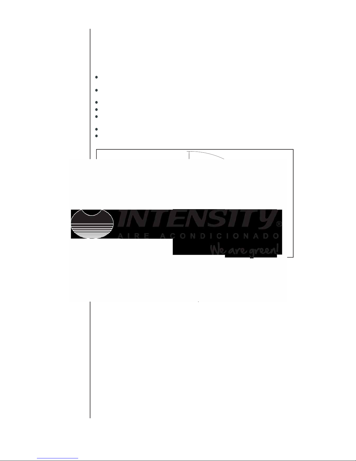
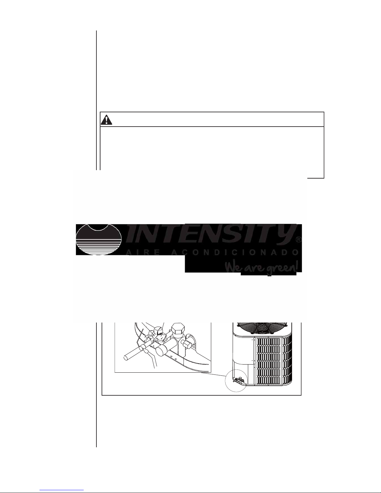
Good Refrigeration practices require the installation of a field supplied liquid line
drier, as shown in Fig.1.
Fig.1 Filter-Drier installation
LIQUID-LINE FILTER-DRIER
It will be more convenient to open
the Service valve after removing
the Underside Clapboard.
NOTE
LARGE SERVICE VALVE
SMALL SERVICE VALVE
FIELD SUPPLIED AND INSTALLED

5
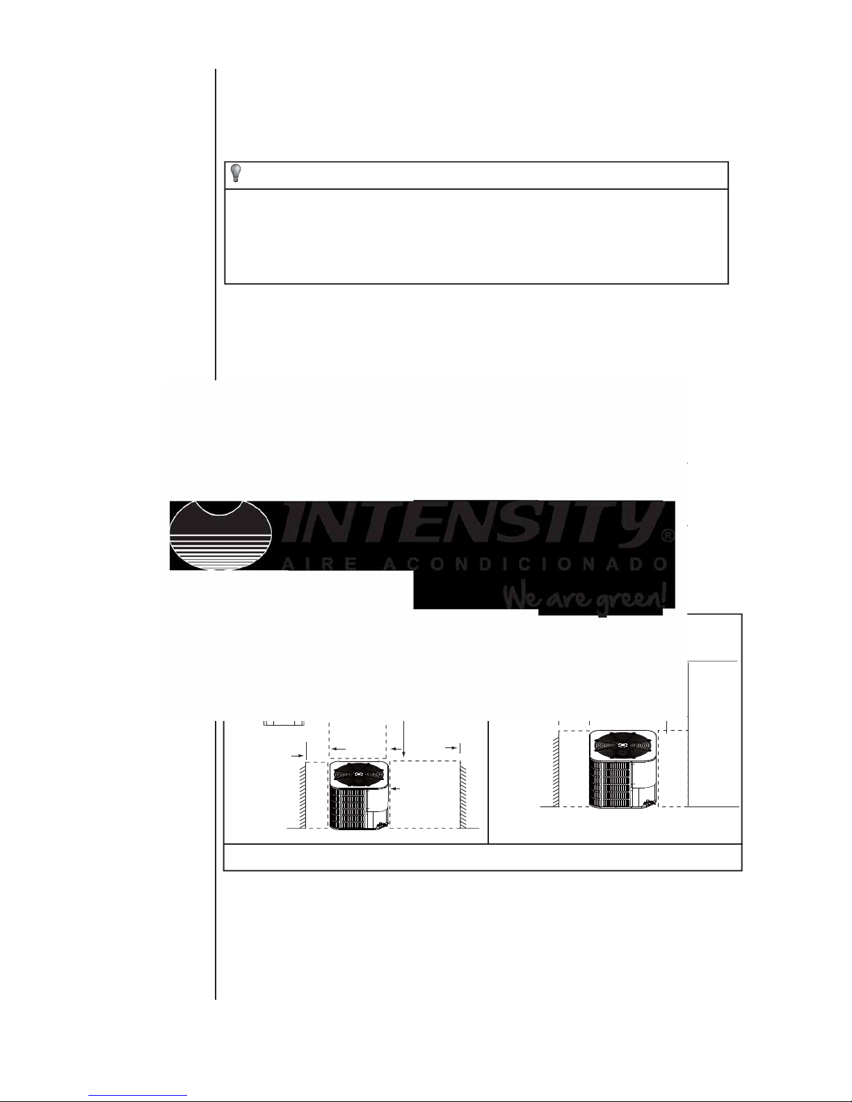
DIMENSIONAL DATA
"H" in. [mm] "W" in. [mm]
"L" in. [mm]
Liquid in.
Suction in.
29-1/8[740] 29-1/8[740]
29-1/8[740] 29-1/8[740]
29-1/8[740] 29-1/8[740]
29-1/8[740] 29-1/8[740]
MODEL SIZE
Dimensions (Inches)
Refrigerant Connection
Service Valve Size
24-15/16[633]
3/8
3/8
3/8
3/8
3/4
3/4
7/8
7/8
24-15/16[633]
33-3/16[843]
33-3/16[843]
36
36
AC HP
24 24
48
48
60
60
FIG.2 DIMENSIONS
SUCTION LINE
CONNECTION
CONTROL WIRING
7/8” (22.2mm)
KNOCKOUT
1-11/32” (34.5mm)
LIQUID LINE
CONNECTION
SERVICE
FITTING
SERVICE
FITTING
POWER WIRING
SEE DETAIL A
DETAIL A
HOLE
1-3/32” (27.8mm)
NOTE: GRILL APPEARANCE
MAY VARY.
NOTES: 1 AC: Air Condition er ; HP: Heat Pump;
AIR DISCHARGE: ALLOW 60”
MINIMUM CLEARANCE.
SERVICE ACCESS
ALLOW 24” CLEARANCE
AIR INLETS
LOUVERED PANELS
ALLOW 18”
MINIMUM
CLEARANCE
W
3.0 UNIT INSTALLATION
3.1 LOCATION
Before starting the installation, select and check the suitability of the location for both
the indoor and outdoor unit. Observe all limitations and clearance requirements. The
outdoor unit must have sufficient clearance for air entrance to the condenser coil, for air
discharge and for service access. See Fig.2
NOTE
For multiple unit installations, units must be spaced a minimum of 18 inches
apart. (Coil face to coil face.)
If the unit is to be installed on a hot sun exposed roof or a black-topped ground area, the
unit should be raised sufficiently above the roof or ground to avoid taking the accumulated layer of hot air into the outdoor unit.
Provide an adequate structural support.
WARNING
The outdoor unit should not be installed in an area where mud or ice could cause
personal injury or system damage.
Elevate the unit sufficiently to prevent any blockage of the air entrances by snow in
areas where there will be snow accumulation. Check the local weather bureau for the
expected snow accumulation in your area. Isolate the unit from rain gutters to avoid any
possible wash out of the foundation.
When installing units on a roof, the structure must be capable of supporting the total
weight of the unit, including a padded frame unit, rails, etc., which should be used to
minimize the transmission of sound or vibration into the conditioned space.
3.3 ROOF INSTALLATION
3.4 UNIT PLACEMENT
1. Provide a base in the pre-determined location.
2. Remove the shipping carton and inspect for possible damage.
3. Compressor tie-down nuts should remain tightened.
4. Position the unit on the base provided.
The unit may be installed at ground level on a solid base that will not shift or settle, causing strain on the refrigerant lines and possible leaks. Maintain the clearances shown in
Fig.2 and install the unit in a level position.
3.2 GROUND INSTALLATION
Normal operating sound levels may be objectionable if the unit is placed directly under
windows of certain rooms (bedrooms, study, etc.).
Top of unit discharge area must be unrestricted for at least 60 inches above the unit.
6
CAUTION
This system uses R410A refrigerant which operates at higher pressure than
R-22. No other refrigerant may be used in this system. Gauge sets, hoses,
refrigerant containers, and recovery system must be designed to handle
R410A. If you are unsure, consult the equipment manufacturer.
The outdoor unit must be connected to the indoor coil using field supplied refrigerant
grade copper tubing that is internally clean and dry. Units should be installed only with
the tubing sizes for approved system combinations. The refrigerant charge shown in
the nameplate is for standard size interconnecting liquid line lengths up to 15 feet.
7
NOTE
Using a larger than specified line size could result in oil return problems. Using a
too small line will result in loss of capacity and other problems caused by insufficient refrigerant flow. Slope horizontal suction lines at least 1" every 20 feet
toward the outdoor unit to facilitate proper oil return.
3.5 Unit Location Considerations
• Ensure the top discharge area is unrestricted for at least 5 feet above the unlt.
• Provide at least 3 feet clearance in front of the control box (access panels) and any other
side requiring service.
• Do not locate close to bedrooms as operational sounds may be objectionable.
• Avoid locations near windows and similar areas where condensation and freezing defrost
vapor can annoy a customer.
• Position the outdoor unit a minimum of 12" from any wall or surrounding shrubbery to
ensure adequate airflow.
• Outdoor unit location must be far enough away from any structure to prevent excess roof
runoff water or Icicles from ralling directly on the unit.
• Position the outdoor unit a minimum of 12" from any wall or surrounding shrubbery to
ensure adequate airflow.
• Outdoor unit location must be far enough away from any structure to prevent excess roof
runoff water or icides from ralling directly on the unit.
Avoid install
near bedrooms
Min 5 feet unrestricted
Min 3 feet
unrestricted
Min 12"
to wall
Min 20 inches
to shrubbery
Min 12" to
shrubbery
Access panel
1. suggested Locations for Best Reliability
Fig. 3 suggested Locations for Best Reliability

8
3.6 UNIT MOUNTING
2 . If elevating a unit on a flat roof , use 4”× 4”(or equivalent) stringers
positioned to distribute unit weight evenly and prevent noise and vibration (See Fig.3).
NOTE:Do not block drain openings shown in Fig.5.
3. If unit must be elevated because of anticipated snow fall, secure unit and
elevating stand such that unit and/or stand will not tip over or fall off.
If elevating the heat pump, either on a flat roof or on a slab, observe the following guidelines.
1. The base pan provided elevates the heat pump 2” above the base pad.
NOTE: To tie down unit, see 3.6.
BASE PAD
(CONCRETE OR
OTHER SUITABLE
MATERIAL)
Note: It is recommended that these precautions be taken for units being installed in areas
where snow accumulation and prolonged below-freezing temperatures occur.
• Units should be elevated 3-12 inches above the pad or rooftop, depending on local
weather. This additional height will allow drainage of snow and ice melted durIng defrost
cycle prior to its refreezlng. Ensure that drain holes in unit base pan are not obstructed,
preventing drainage of defrost water.
• If possible, avoid locations that are likely to accumulate snow drifts. if not possible, a snow
drift barrier should be installed around the unit to prevent a build-up of snow on the sides of
the unit.
Min 12"
Snow
barrier
3- 12" Elevation
Snow legs
pad
2. Cold Climate Considerations (Heat Pump Only)
Fig.4 Cold Climate Considerations (Heat Pump Only)
BASE PAN (BOTTOM
VIEW) DO NOT OBSTRUCT
DRAIN HOLES
(SHADED)
ELEVATION ABOVE
ANTICIPATED
SNOW IS NECESSARY
Fig.5 RECOMMENDED ELEVATED INSTALLATION
1. Install the lines with as few bends as possible. Care must be taken not to damage
the couplings or kink the tubing. Use clean hard drawn copper tubing where no
appreciable amount of bending around obstruction is necessary, if soft copper must
be used, care must be taken to avoid sharp bends which may cause a restriction.
2. The lines should be installed so that they will not obstruct service access to the coil,
air handling system or filter.
3.8 PRECAUTIONS DURING LINE INSTALLATION
9
3.7 FACTORY-PREFERRED TIE-DOWN METHOD
Step 3: Using field supplied L-shaped bracket to locate holes on concrete and drill pilot
holes which is at least 1/4” deeper than fastener being used.
IMPORTANT
Self drilling screws to base pan should not exceed 3/8” long to avoid damaging
coil.
Step 4: Using conventional practices to install brackets, tighten concrete fasteners and
self-tapping screws (See Fig.6).
NOTE
NOTE
: 1. One bracket for each side. For extra stability, 2 brackets for each side.
2. Do not over-tighten the concrete fastener to avoid weakening the concrete.
Step 1: Prior to installing clear pad of debris.
IMPORTANT
Then cement pad must meet local codes and must be the proper thickness to
accommodate fasteners.
Step 2: Center and level unit onto pad.
IMPORTANT NOTE:
These instructions are intended to provide a method to tie-down system to cement slab
as a securing procedure for high wind areas. It is recommended to check Local Codes
for tie-down methods and protocols.
REQUIRED PARTS LIST
SEE DETAIL B
#7 X 3/8” Self Tapping Screws
(Don’t Exceed 3/8” long)
1/4” 1-1/2” Hex Washer Head Concrete Screws
(3/16” Pilot Hole Needed. Pilot Hole Should Be1/4” Deeper
Than The Fastener Embedment)
Fig.6 PREFERRED TIE-DOWN METHOD
DETAIL B
Brackets:
2” width, 1/16” thickness,
height as required.
Available from distributor
or in market place.
The dimension see FIG.2

3. Care must also be taken to isolate the refrigerant lines to minimize noise transmis sion from the equipment to the structure.
4. The suction line must be insulated. Tape and suspend the refrigerant lines as shown.
DO NOT allow tube metal-to-metal contact. See Fig.7.
5. Use PVC piping as a conduit for all underground installations as shown in Fig.8.
Buried lines should be kept as short as possible to minimize the build up of liquid
refrigerant in the suction line during long periods of shutdown.
6. Pack a sealing material such as perma gum around refrigerant lines where they
penetrate a wall to reduce vibration and to retain some flexibility.
Insu la ted Liquid Line
Tape
Shee t Me tal Hanger
opt iona l
Sug gest ed
Incorrect
Fig.7 Tubing Hanger
Fig.8 Underground Installation
10
Insu la ted Suction Line
Fig.9
Typical Installation
TO
INDO OR
BLOW ER
TO
POWE R
SUPPLY
TO
COIL
WEATHERPR OOF
DISCONNECT
SWIT CH
Seal o pening(s) with
perm agum or equivalen t
24V co ntrol signal
NOTE :All outdoor wiri ng m ust be weather proo f
All outdoor unit and evaporator coil connections are copper-to-copper and should be
brazed with a phosphorous-copper alloy material such as Silfos-5 or equivalent. DO
NOT use soft solder. The outdoor units have reusable service valves on both the liquid
and suction connections. The total system refrigerant charge is retained within the
outdoor unit during shipping and installation. The reusable service valves are provided
to evacuate and charge per this instruction.
Serious service problems can be avoided by taking adequate precautions to assure an
internally clean and dry system.
3.9 PRECAUTIONS DURING BRAZING OF LINES
CAUTION
Dry nitrogen should always be supplied through the tubing while it is being
brazed, because the temperature required is high enough to cause oxidation
of the copper unless an inert atmosphere is provide. The flow of dry nitrogen
should continue until the joint has cooled. Always use a pressure regulator
and safety valve to insure that only low pressure dry nitrogen is introduced into
the tubing.Only a small flow is necessary to displace air and prevent oxidation.
Precautions should be taken to prevent heat damage to service valve by wrapping a wet
rag around it as shown in Fig.10. Also, protect all painted surfaces, insulation, during
brazing. After brazing cool joint with wet rag.
3.10 PRECAUTIONS DURING BRAZING SERVICE VALVE
The valve can be opened by removing the plunger cap and fully inserting a hex wrench
into the stem and backing out counter-clockwise until valve stem just touches the chamfered retaining wall.
11
1. Remove the cap and Schrader core from both the liquid and suction service valve
service ports at the outdoor unit. Connect Iow pressure nitrogen to the liquid line
service port.
Connect the refrigerant lines using the following procedure:
2. Braze the liquid line to the liquid valve at the outdoor unit. Be sure to wrap the valve
body with a wet rag. Allow the nitrogen to continue flowing. Refer to the Tabular Data
Sheet for proper liquid line sizing.
3. Carefully remove the rubber plugs from the evaporator liquid and suction connections
at the indoor coil.
Fig.10 Heat Protection
service valve
wet rag

4. Braze the liquid line to the evaporator liquid connection. Nitrogen should be flowing
through the evaporator coil.
5. Slide the plastic cap away from the suction connection at the indoor coil. Braze the
suction line to the evaporator suction connection. Refer to the Table 1 for proper
suction line sizing.
6. Protect the suction valve with a wet rag and braze the suction line connection to the
outdoor unit. The nitrogen flow should be exiting the system from the suction service
port connection. After this connection has cooled, remove the nitrogen source from
the liquid fitting service port.
7. Replace the Schrader core in the liquid and suction valves.
8. Leak test all refrigerant piping connections including the service port flare caps to be
sure they are leak tight. DO NOT OVER TIGHTEN (between 40 and 60 inch -lbs.
maximum).
9. Evacuate the suction line, evaporator, and the liquid line, to 350 microns or less.
Table 1: Recommended Liquid and Suction Tube Diameters (ln.)
MODEL
SIZE
LIQUID
SUCTION
Tube Diameter
Tube Diameter
24 3/8 3/4
36 3/8 3/4
48 3/8
60 3/8 7/8
12
7/8
10. Replace cap on service ports. Do not remove the flare caps from the service ports
except when necessary for servicing the system.
11. Release the refrigerant charge into the system. Open both the liquid and suction
valves by removing the plunger cap and with an hex wrench back out counter
-clockwise until valve stem just touches the chamfered retaining wall.
12. Replace plunger cap finger tight, then tighten an additional 1/12 turn (1/2 hex flat).
Cap must be replaced to prevent leaks.
WARNING
Never attempt to repair any brazed connections while the system is under pressure. Personal injury could result.
See "System Charge" section for checking and recording system charge.
4.0 INTERCONNECTING TUBING
4.1 SUCTION AND LIQUID LINES
Keep all lines sealed until connection is made.
Make connections at the indoor coil first.
Refer to Li ne Size Information in Ta bles 2 and 3 for correct size and multipliers to be
used to determine capacity for various suction line diameters and lengths of run. The
losses due to the lines being exposed to outdoor conditions are not included.
The factory refrigerant charge in the outdoor unit is sufficient for 15 feet of standard
size interconnecting liquid line. Calculate actual charge required with installed liquid
line size and length as below.
5/16” ± .4 oz. per foot
3/8” ± .6 oz . per foot
1/2” ± 1.2 oz . per foot
 Loading...