

Page 1
Interfaz PA-AW2-MBS-1 FW:1.0
Interface PA-AW2-MBS-1 FW:1.0
1 / 2
© Intesis Software S.L.U. - Todos los derechos reservados/ All rights reserved
IntesisBox es una marca registrada de / is a registred trademark of Intesis Software SLU
La información en este documento puede variar sin previo aviso. / This information is subject to change without notice.
Doc. Rev.1.1
URL
Email
Phone
http://www.intesisbox.com
info@intesisbox.com
+34 938047134
• Esta interfaz debe ser instalado por personal técnico
acreditado (electricista, instalador, o personal técnico
cualificado) y siguiendo todas las instrucciones de
seguridad.
• Antes de manipular el interior de la unidad Aquarea H,
asegúrese de que está completamente desconectada de la
red eléctrica.
• En caso de instalación mural del interfaz junto a la unidad
Hydro, fije la interfaz de forma segura siguiendo las
instrucciones del diagrama de abajo.
• La interfaz debe ser instalada en una ubicación con acceso
restringido.
• This interface must be installed by accredited technical
personnel (electrician, installer, or technical personnel) and
following all the safety instructions.
• Before manipulating the Aquarea H unit, make sure it is
completely disconnected from Mains power.
• In case of wall mounting of the interface beside the Hydro
unit, fix the interface safely following the instructions of the
diagram below.
• This interface must be installed in an access restricted
location.
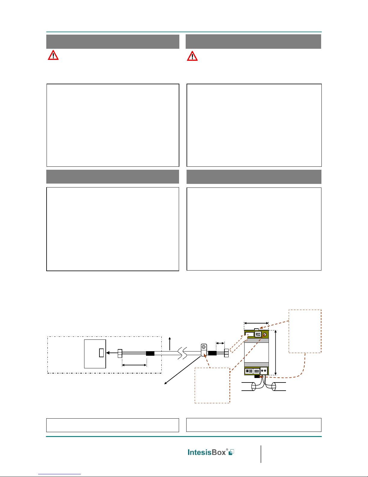
• Desconecte la unidad aire agua de la red eléctrica.
• Fije la interfaz a la pared junto a la unidad de aire agua
siguiendo las instrucciones del diagrama de abajo (respete
las instrucciones de seguridad anteriores).
• Conecte el extremo largo del cable suministrado al conector
de la unidad hidrónica y el otro extremo al conector “Hydro
Unit” de la pasarela IntesisBox.
• Conecte el bus EIA-485 al conector EIA485 de la interfaz.
Respete la polaridad.
• Tape la unidad hidrónica y vuelva a conectarla a la red
eléctrica.
• Siga las instrucciones del manual de usuario para la
configuración y puesta en servicio de la interfaz.
• Siga las instrucciones de la página siguiente para
configurar la interfaz a través de los micro interruptores.
• Disconnect the air to water unit from the Mains Power.
• Attach the interface next to the Air to Water unit (wall
mounting) following the instructions of the diagram below
(respect the safety instructions given above).
• Connect the long end of the supplied cable in the connector
of the hydro unit and the other end into the “Hydro Unit”
connector of the IntesisBox gateway.
• Connect the EIA-485 bus to the connector EIA485 of the
interface.
• Close the hydro unit and reconnect it to Mains Power.
• Follow the instructions on the user’s manual to configure
and commission the interface.
• Follow the instructions of the next page to configure the
interface through on-board DIP-switches.
WARNING
ATENCIÓN
Siga atentamente estas instrucciones de seguridad e
instalación. Un manejo inadecuado puede ocasionar daños
graves para su salud y daños irreparables en la interfaz y/o
en la unidad interior del aire acondicionado.
Follow carefully this safety and installation instructions. Not
proper work may lead to a serious damage for your health and
may harm seriously the interface and/or the AC indoor unit.
IMPORTANTE: La ampliación o acortamiento del cable
de conexión que se incluye con la interfaz puede provocar un
funcionamiento incorrecto. Mantenga el cable de conexión lo
mas alejado posible del cableado eléctrico y del cable de
tierra, no los enrolle juntos.
IMPORTANT: Extending or shortening the connection
cable included with the interface may cause the interface not
working properly. Keep the connection cable as far away as
possible from electrical wires and ground wire. Do not bundle
them together.
Instrucciones de seguridad
Safety intructions
Instrucciones de instalación
Installation instructions
CN-CNT
Unidad Hidrónica
Hydro unit
Tarjeta control interior
Internal control board
200 mm / 7.9”
40 mm / 1.6”
Cable de conexión
suministrado con el
interfaz.
Connection cable
supplied with the
interface.
Tornillo de fijación
Fixing screw
90 mm
3.5”
IntesisBox®
PA-AW2-MBS-1
MODBUS RTU
EIA-485
Bus
EIA485
A B
Hydro Unit
53 mm / 2.1”
Para fijación mural,
extraiga hacia fuera
las grapas superior
e inferior hasta oir
el "click".
For wall mounting,
extract the upper
and lower staples
until you hear the
"click".
Use este agujero
para fijar el cable con
la grapa y tornillo
suministrados.
Use this hole to
attach the cable
using the staple and
screw provided.
El manual de usuario está disponible en:
https://www.intesisbox.com/en/pan asonic-modbus-air-to-water-pa-aw2-mbs-1/gateway/
The user manual is available at:
https://www.intesisbox.com/en/pan asonic-modbus-air-to-water-pa-aw2-mbs-1/gateway/
Page 2
Interfaz PA-AW2-MBS-1 FW:1.0
Interface PA-AW2-MBS-1 FW:1.0
2 / 2
© Intesis Software S.L.U. - Todos los derechos reservados/ All rights reserved
IntesisBox es una marca registrada de / is a registred trademark of Intesis Software SLU
La información en este documento puede variar sin previo aviso. / This information is subject to change without notice.
Doc. Rev.1.1
URL
Email
Phone
http://www.intesisbox.com
info@intesisbox.com
+34 938047134
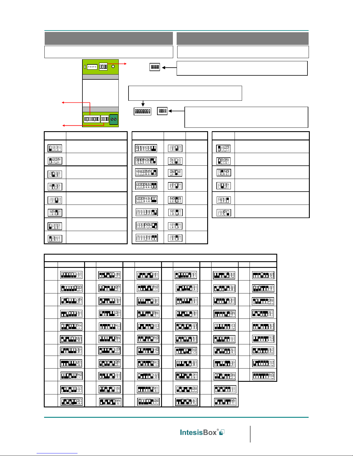
IMPORTANTE: Es necesario resetear el e quipo (quitar tensión) tras modificar
la configuración de los micro interruptores para que ésta se aplique.
IMPORTANT: It is required to reboot or power cycle the interface every time the
DIP switch configuration changes.
SW1-P1
Descripción
Description
SW3-P7..8
SW4-P3
Descripción
Description
SW4-P1..2-4
Descripción
Description
Los límites de temperatura vienen marcados por lo propia
configuración de la Unidad Aquarea (Valor por defecto)
Set point limits are defined by the configuration of Aquarea
Unit (Default value).
2400bps
Los valores de temperatura en los registros Modbus se representan en
decigrados (x10)
Temperature values in Modbus register are represented in decidegrees
(x10)
Los límites de temperatura serán los máximos permitidos
por el fabricante sin tener en cuenta la Unidad Aquarea.
Set point limits will be the maximum ones allowed by the
manufacturer, not considering the specific Aquarea Unit
4800bps
Los valores de temperatura en los registros Modbus se representan en
grados (x1) (Valor por defecto).
Temperature values in Modbus register are represented in degrees (x1)
(Default value).
Reserved, not used (Default value)
Reservado, no usado (Valor por defecto)
9600bps
(Valor por defecto
default value)
Los valores de temperatura en los registros Modbus se representan en
grados Fahrenheit
Temperature values in Modbus register are represented in Fahrenheit
degrees
Reserved, not used
Reservado, no usado
19200bps
Los valores de temperatura en los registros Modbus se representan en
grados Celsius (Valor por defecto)
Temperature values in Modbus register are r epresented in Celsius
degrees (Default value)
Reserved, not used (Default value)
Reservado, no usado (Valor por defecto)
38400bps
Resistencia interna de 120Ω conectada al bus EIA-485
Internal termination resistor of 120Ω connect ed to EIA-485 bus
Reserved, not used
Reservado, no usado
57600bps
Bus EIA-485 sin resistencia de terminación (V alor por defecto).
EIA-485 bus without termination resistor (Default value).
Reserved, not used (Default value)
Reservado, no usado (Valor por defecto)
76800bps
Reserved, not used
Reservado, no usado
115200bps
Dirección de esclavo Modbus - Modbus Slave address
Direcc
Add
SW3-P1..6
Direcc
Add
SW3-P1..6
Direcc
Add
SW3-P1..6
Direcc
Add
SW3-P1..6
Direcc
Add
SW3-P1..6
Direcc
Add
SW3-P1..6
0
11
22
33
44
55
1
12
23
34
45
56
2
13
24
35
46
57
3
14
25
36
47
58
4
15
26
37
48
59
5
16
27
38
49
60
6
17
28
39
50
61
7
18
29
40
51
62
8
19
30
41
52
63
9
20
31
42
53
10
21
32
43
54
Configuración del número de esclavo Modbus y baudios.
Configuration of Modbus Slave number and baud rate.
Configuración de los baudios, magnitud temperatura (x1/x10), unidades de
temperatura (ºC/ºF) y resistencia de terminación de EIA-485.
Configuration of baud rate, temperature magnitude (x1/x10), temperature
units (Cº/Fº) and termination resistor for EIA-485.
IntesisBox®
PA-AW2-MBS-1
EIA485
A B
Hydro Unit
SW3
SW4
SW1
1 2 3 4
SW1
1 2 3 4
SW4
1 2 3 4 5 6 7 8
SW3
Configuración de los límites de temperatura de consigna
Set point limits’ configuration
ON
ON
ON
ON
ON
ON
ON
ON
ON
Configuración por micro interruptores
Configuration through DIP switches
ON
ON
ON
ON
ON
ON
ON
ON
ON
ON
ON
ON
ON
ON
ON
ON
ON
ON
ON
ON
ON
ON
ON
ON
ON
ON
ON
ON
ON
ON
ON
ON
ON
ON
ON
ON
ON
ON
ON
ON
ON
ON
ON
ON
ON
ON
ON
ON
ON
ON
ON
ON
ON
ON
ON
ON
ON
ON
AC UNIT
ON
ON
ON
ON
ON
ON
ON
ON
ON
ON
ON
ON
ON
ON
ON
ON
ON
ON
ON
ON
ON
ON
ON
ON
ON
ON
ON
ON
ON
ON
 Loading...