

Page 1

IntesisBox® LON - KNX
Doc. Rev.3
Installation Manual
URL
email
tel
http://www.intesis.com
info@intesis.com
+34 938047134
1 / 6
This information is subject to change without notice.
IntesisBox must be installed by accredited electrician or similar technical personnel, following all the safety instructions
given here, and in accordance always with the country legislation for installation of electric equipment.
IntesisBox can not be installed outdoors or exposed to direct solar radiation, water, high relative humidity or dust.
IntesisBox must only be installed in a restricted access location
In case of wall mount, fix firmly IntesisBox on a not vibrating surface following the instructions below.
In case of DIN rail mount fix IntesisBox properly to the DIN rail following the instructions below.
Mounting on DIN rail inside a metallic cabinet properly connected to earth is recommended.
Disconnect always power of any wires before manipulating and connecting them to IntesisBox.
A power supply with an NEC Class 2 or Limited Power Source (LPS) and SELV rated is to be used.
Respect always the expected polarity of power and communication cables when connecting them to IntesisBox.
Supply always a correct voltage to power IntesisBox, see details of voltage range admitted by the device in the technical
characteristics below.
This device was designed for installation in an enclosure. To avoid electrostatic discharge to the unit in environments with
static levels above 4 kV precautions should be taken when the device is mounted outside an enclosure. When working in
an enclosure (ex. making adjustments, setting switches etc.) typical anti-static precautions should be observed before
touching the unit
Safety Instructions
WARNING
Follow carefully this safety and installation instructions. Improper work may lead to serious harmful for your
health and also may damage seriously the IntesisBox and/or any other equipment connected to it.
Use the software LinkBoxLON to configure IntesisBox, follow the instructions of the user's manual for more
details.
See instructions to download and install the latest version of LinkBoxLON and
the user's manual at
http://www.intesis.com/down/lon/linkboxlon.html
Configuration and setup
Disconnect from mains the power supply before connecting it to IntesisBox.
Disconnect power of any bus or communication cable before connecting it to IntesisBox.
Mount IntesisBox on the wall or DIN rail following the instruction given below, respecting the safety
instructions given above.
Connect a NEC Class 2 or Limited Power Source (LPS) and SELV rated power supply to IntesisBox,
respect the polarity if DC power or Line and Neutral if AC power. Apply always a voltage within the range
admitted by IntesisBox and of enough power (see technical characteristics).
Circuit-breaker must be used before the power supply. Rating 250V-6A
Connect the communication cables to IntesisBox, see details on the user's manual.
Power IntesisBox and the rest of devices connected to it.
Installation instructions
Page 2
IntesisBox® LON - KNX
Doc. Rev.3
Installation Manual
URL
email
tel
http://www.intesis.com
info@intesis.com
+34 938047134
2 / 6
This information is subject to change without notice.
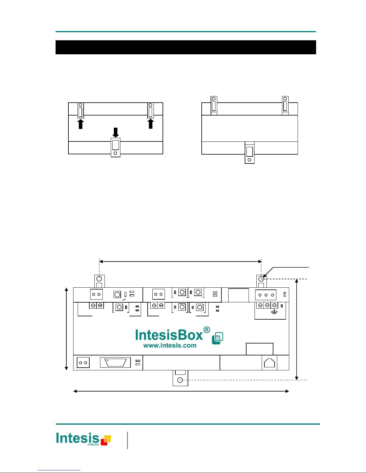
1. Separate the fixing clips in the bottom of the box, pushing them to the outside until hear the "click" which
indicates that now the clips are in position for wall mount, see in the figure below.
2. Use the holes of the clips to fix the box in the wall using screws. Use the template below for the wall holes.
Wall mount
Clips in their original position, for DIN rail
mount
Clips in position for wall mount
Top view of the box
Bottom view of the box
114mm
Ø 3mm
LA
LB
PROG / BUS
159mm
105mm
TX
RX
POWER
PC Console
USB
KNX TP-1 (EIB)
+ -
Tx
Rx
PROG/BUS
ETH
10/100 Base-T
+ -
24Vac CMN
ON
9 – 30 Vdc
Max. 210mA
24 Vac
Max. 212mA
50-60Hz
A B
LA
LB
SERVICE 1
SERVICE 2
SERVICE 1
SERVICE 2
LON TP / FT -10
100 mm
Page 3

IntesisBox® LON - KNX
Doc. Rev.3
Installation Manual
URL
email
tel
http://www.intesis.com
info@intesis.com
+34 938047134
3 / 6
This information is subject to change without notice.
With the clips of the box in their original position, insert first the box in the upper edge of the DIN rail and later insert
the box in the down part of the rail, using a small screwdriver and following the steps in the figure below.
DIN rail mount
DIN rail
EN60715 TH35
1 2 3
Side view of the box
Page 4

IntesisBox® LON - KNX
Doc. Rev.3
Installation Manual
URL
email
tel
http://www.intesis.com
info@intesis.com
+34 938047134
4 / 6
This information is subject to change without notice.
Connections
________________________________________________________________________________________
Notes:
1. Must use NEC Class 2 or Limited Power Source (LPS) and SELV rated power supply.
If using DC power supply:
Respect polarity applied of terminals (+) and (-). Be sure the voltage applied is within the range admitted
(9 to 30 Vdc). The power supply can be connected to earth but only through the negative terminal, never
through the positive terminal.
If using AC power supply:
Make sure the voltage applied is of the value admitted (24 Vac). Do not connect any of the terminals of the
AC power supply to earth, and make sure the same power supply is not supplying any other device.
2. Use the software LinkBoxLON to configure IntesisBox. Consult the user's manual for details.
LinkBoxLON
Only for configuration
See Note 2
Console Cable USB
standard 1.8 m.
Supplied.
Serial port
(Not used)
KNX TP-1
(EIB bus)
LON TP/FT-10
(LON bus)
Ethernet Port
(also for
configuration
Intesisbox)
LA
LB
PROG / BUS
TX
RX
POWER
PC Console
USB
KNX TP-1 (EIB)
+ -
Tx
Rx
PROG/BUS
ETH
10/100 Base-T
+ -
24Vac CMN
ON
9 – 30 Vdc
Max. 210mA
24 Vac
Max. 212mA
50-60Hz
Power
See Note 1
A B
LA
LB
SERVICE 1
SERVICE 2
SERVICE 1
SERVICE 2
LON TP / FT -10
Page 5

IntesisBox® LON - KNX
Doc. Rev.3
Installation Manual
URL
email
tel
http://www.intesis.com
info@intesis.com
+34 938047134
5 / 6
This information is subject to change without notice.
Enclosure
Plastic, type PC (UL 94 V-0).
Dimensions: 159mm x 105mm x 58mm.
Color
Grey. RAL 7035.
Power
De 9 a 30Vcc +/-10%, Máx.: 210mA
24Vca +/-10% 50-60Hz, Máx.: 212mA
Must use a NEC Class 2 or Limited Power Source (LPS) and SELV
rated power supply.
Plug-in screw terminal block (2 poles) for 12 AWG cable.
Terminal wiring
(for power supply
and low-voltage
signals)
Per terminal: solid wires or stranded wires (twisted or with
ferrule)
1 core: 0.5mm2… 2.5mm2
2 cores: 0.5mm2… 1.5mm2
3 cores: not permitted
Mounting
Wall
DIN rail EN60715 TH35.
LON Port
1 x LON TP/FT-10. Plug-in screw terminal block (2 poles) for 12
AWG cable. TNV-1
KNX Port
1 x KNX TP1 (EIB) opto isolated. Plug-in screw terminal block (2
poles) for 12 AWG cable. TNV-1
LED indicators
1 x Power.
2 x KNX port activity (Tx, Rx).
2 x Gateway status: LA (LON status), LB (KNX status)
1 x KNX programming.1
2 x LON Service LED.
Switches
1 x KNX programming.1
2 x Service LON.
Console port
USB. Type B female standard connector. SELV
Ethernet port
1 x Ethernet 10/100Base-T connector RJ45.
Configuration
Via USB console port and/or Ethernet interface 2
Firmware
Allows upgrades via USB console port and/or Ethernet interface
Operational
temperature
0°C to +60°C
Operational
humidity
10% to 90%, non condensation
Protection
IP20 (IEC60529).
RoHS conformity
Compliant with RoHS directive (2002/95/CE).
Norms and
standards
CE conformity to EMC directive (2004/108/EC) and Low-voltage
directive (2006/95/EC)
EN 61000-6-2
EN 61000-6-3
EN 60950-1
EN 50491-3
1
Not operational for the moment. Reserved for future use.
2
Standard cable USB type A-B of 1,8 meters length is supplied with the device for connection to a PC USB port for configuring
and monitoring the device. The configuration software, compatible with Windows® operating systems, is also supplied.
Technical characteristics
Page 6
IntesisBox® LON - KNX
Doc. Rev.3
Installation Manual
URL
email
tel
http://www.intesis.com
info@intesis.com
+34 938047134
6 / 6
This information is subject to change without notice.
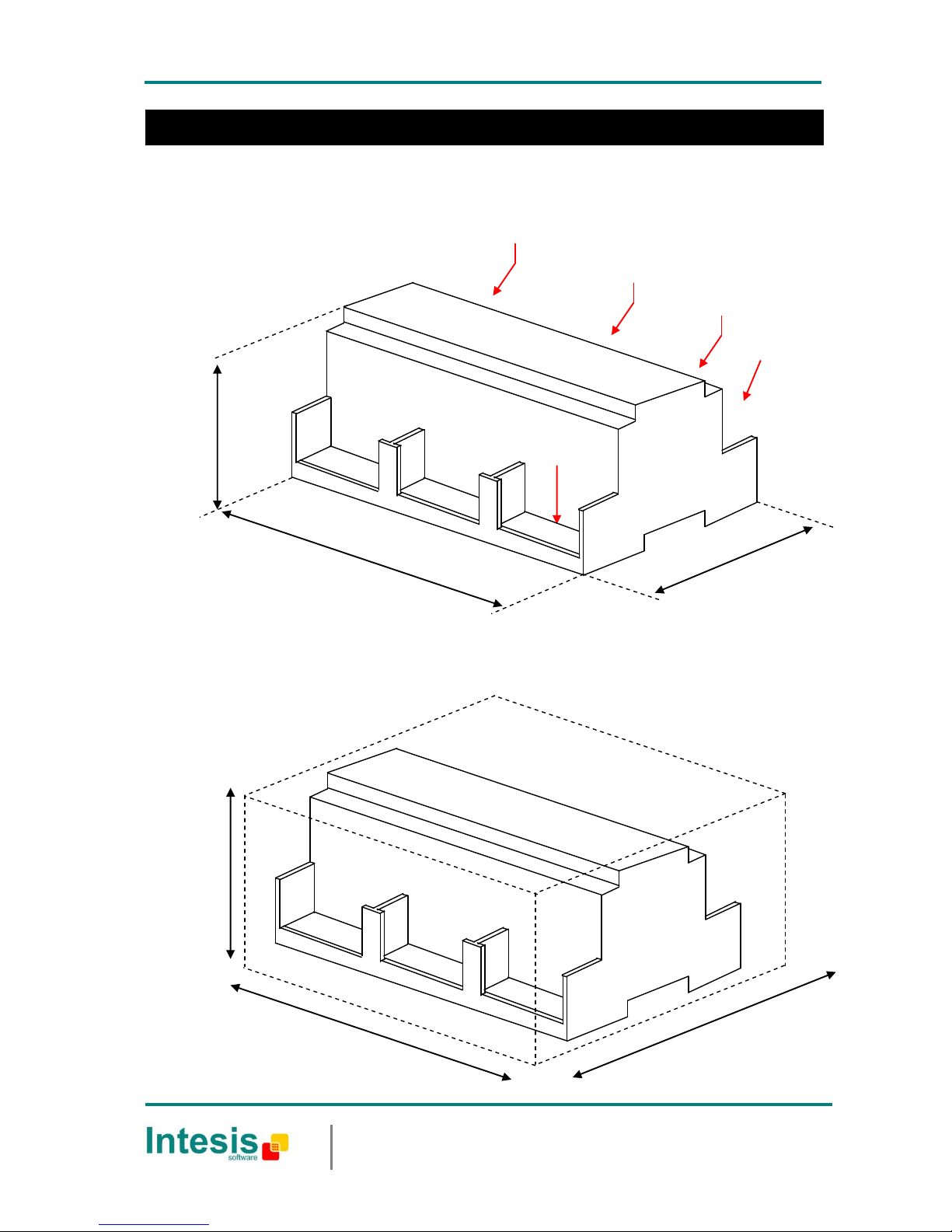
Dimensions
Características técnicas
External dimensions.
Free space recommended to install the device, with spacing enough for external connections.
159 mm
130 mm
60 mm
KNX Port
Power
Console
Port
159 mm
105 mm
58 mm
LON Port
Ethernet Port
 Loading...