

IntesisBox KNX-Mitsubishi Electric G-50A, KNX-Mitsubishi Electric GB-50 A, KNX-Mitsubishi Electric GB-50ADA, KNX-Mitsubishi Electric AG-150A User Manual
Page 1

IntesisBox
®
KNX
Mitsubishi Electric G-50A/GB-50A/GB-50ADA/AG-150A
User's Manual
Issue date: 04/2018
r23 eng
Page 2

IntesisBox
®
KNX - Mitsubishi Electric G50
User’s Manual r23 eng
© Intesis Software S.L.U. - All rights reserved
This information is subject to change without notice
IntesisBox® is a registered trademark of Intesis Software SLU
URL
Email
tel
http://www.intesisbox.com
info@intesisbox.com
+34 938047134
2 / 28
© Intesis Software S.L.U. All Rights Reserved.
Information in this document is subject to change without notice. The software described in
this document is furnished under a license agreement or nondisclosure agreement. The
software may be used only in accordance with the terms of those agreements. No part of this
publication may be reproduced, stored in a retrieval system or transmitted in any form or any
means electronic or mechanical, including photocopying and recording for any purpose other
than the purchaser’s personal use without the written permission of Intesis Software S.L.U.
Intesis Software S.L.U.
Milà i Fontanals, 1 bis
08700 Igualada
Spain
TRADEMARKS
All trademarks and trade names used in this document are acknowledged to be the copyright of their respective holders.
Page 3

IntesisBox
®
KNX - Mitsubishi Electric G50
User’s Manual r23 eng
© Intesis Software S.L.U. - All rights reserved
This information is subject to change without notice
IntesisBox® is a registered trademark of Intesis Software SLU
URL
Email
tel
http://www.intesisbox.com
info@intesisbox.com
+34 938047134
3 / 28
Gateway for integration of Mitsubishi Electric City
Multi air conditioning systems into KNX TP-1 (EIB)
control systems.
Two models are available for this gateway, with the following Order Codes:
ME-AC-KNX-15
Model supporting integration of up to 15 City Multi groups.
ME-AC-KNX-100
Model supporting integration of up to 100 City Multi groups.
Page 4

IntesisBox
®
KNX - Mitsubishi Electric G50
User’s Manual r23 eng
© Intesis Software S.L.U. - All rights reserved
This information is subject to change without notice
IntesisBox® is a registered trademark of Intesis Software SLU
URL
Email
tel
http://www.intesisbox.com
info@intesisbox.com
+34 938047134
4 / 28
INDEX
1. Description ...................................................................................................... 5
1.1 Introduction ................................................................................................. 5
1.2 Functionality ................................................................................................. 6
1.3 Capacity of IntesisBox ................................................................................... 7
2. Interfaces ........................................................................................................ 8
2.1 KNX TP-1 (EIB) ............................................................................................. 8
2.2 Mitsubishi Electric G50 ................................................................................... 9
3. Quick Setup ................................................................................................... 12
4. Connections ................................................................................................... 13
4.1 Power device .............................................................................................. 13
4.2 Connect to KNX ........................................................................................... 14
4.3 Connect to G50 ........................................................................................... 14
4.4 Connect to PC (LinkBoxEIB) .......................................................................... 14
5. LinkBoxEIB. Configuration & monitoring tool for IntesisBox® KNX series ................ 15
5.1 Project configuration .................................................................................... 15
5.1.1 Connection configuration ........................................................................ 16
5.1.2 Signals list ........................................................................................... 19
5.1.3 Saving the configuration ........................................................................ 24
6. IntesisBox® and ETS ....................................................................................... 25
6.1 Integration of IntesisBox® in ETS .................................................................. 25
7. Mechanical & electrical characteristics ............................................................... 26
8. Dimensions.................................................................................................... 27
9. Annexes ........................................................................................................ 28
9.1 Gateways Mitsubishi Electric G-50A, GB-50A, GB-50ADA, AG-150A and AE-200A/E
28
Page 5

IntesisBox
®
KNX - Mitsubishi Electric G50
User’s Manual r23 eng
© Intesis Software S.L.U. - All rights reserved
This information is subject to change without notice
IntesisBox® is a registered trademark of Intesis Software SLU
URL
Email
tel
http://www.intesisbox.com
info@intesisbox.com
+34 938047134
5 / 28
1. Description
1.1 Introduction
IntesisBox KNX - Mitsubishi Electric G50 is a communication gateway for the integration of
Mitsubishi Electric City Multi air conditioning systems into KNX TP-1 (EIB).
The aim of this integration is to make accessible the Mitsubishi Electric City Multi AC system
signals and resources from a KNX system, as if it was a part of the own KNX system. For this,
IntesisBox KNX - Mitsubishi Electric G50 acts as a KNX device in the KNX installation allowing
any KNX device to read and write its internal points.
This integration requires the Mitsubishi Electric City Multi AC system be equipped with the
Mitsubishi Electric G-50A, GB-50A, GB-50ADA, EB-50, AG-150A, AE-200A (G50 from now on)
gateway. More specific information about this gateway can be found in section 2.2.
NOTE: Please, remember that Mitsubishi Electric AG-150A requires a
software license, PC-Monitoring license (SW-Mon), that must be purchased
together with the AG-150A gateway.
!
Page 6
IntesisBox
®
KNX - Mitsubishi Electric G50
User’s Manual r23 eng
© Intesis Software S.L.U. - All rights reserved
This information is subject to change without notice
IntesisBox® is a registered trademark of Intesis Software SLU
URL
Email
tel
http://www.intesisbox.com
info@intesisbox.com
+34 938047134
6 / 28
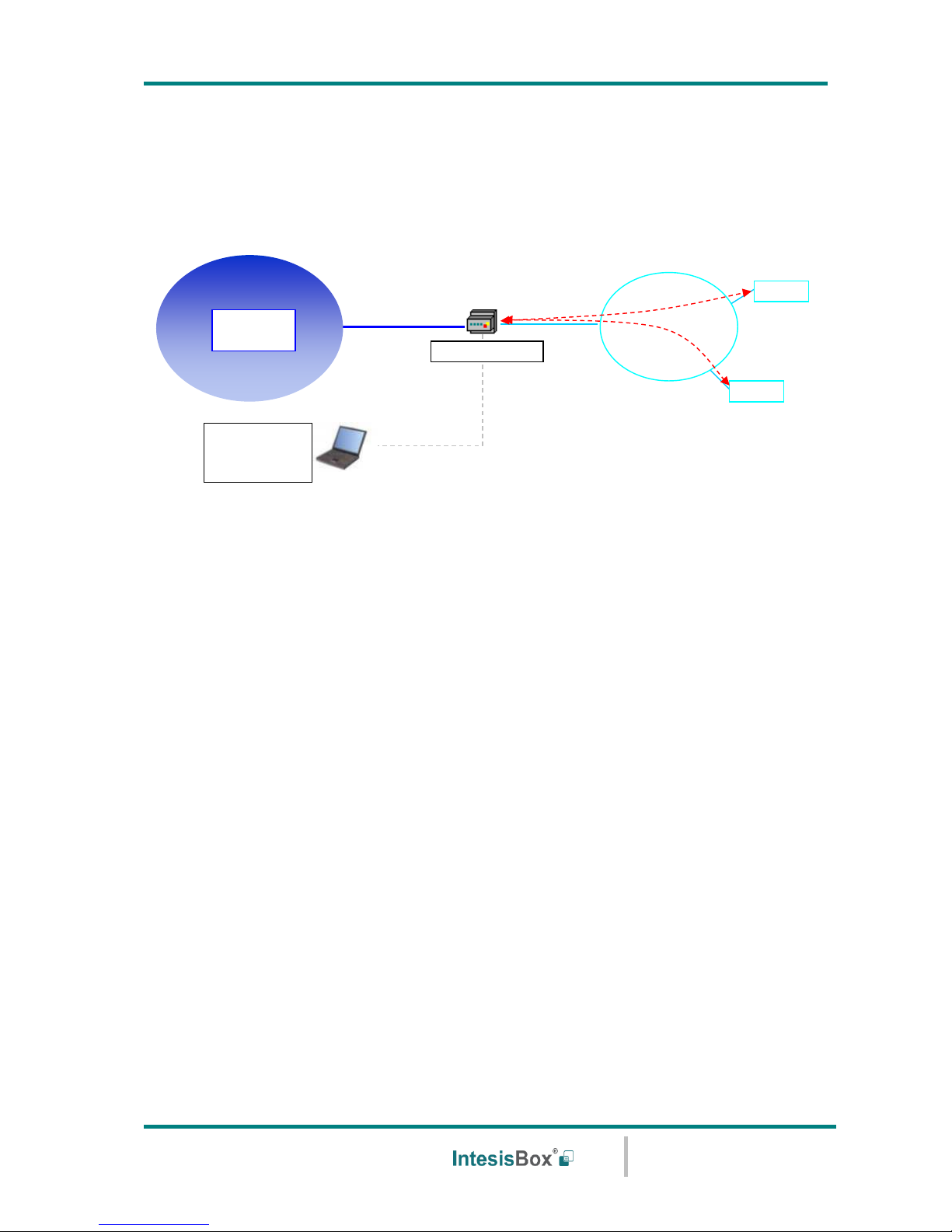
1.2 Functionality
Every one of the mentioned signals have to be associated to an KNX group address, with this,
all the system is seen as a one more KNX device, with the same configuration and functioning
characteristics.
IntesisBox KNX continuously polls (read) all the G50's configured signals and maintains the
updated status of all of them in its memory ready to be served when requested from KNX.
When a change of status is detected in a Mitsubishi Electric signal, a write telegram is sent to
the KNX bus, of the associated KNX Group.
When it is received a telegram from the KNX bus, of a KNX Group address associated to a
Mitsubishi Electric signal, a message is sent immediately to the corresponding G50 to perform
the corresponding action in the Mitsubishi Electric system.
In the continuous polling of the G50, if a non-response of the G50 is detected, the
corresponding virtual signal inside the gateway will be activated indicating communication
error with the G50. The same way, there is also a virtual signal per every City Multi group to
indicate communication error with the group, this signal will be normally activated if the group
is not configured inside the G50. Note that, although the internal units are not connected
physically in the City Multi system, the G50 responds as if they were.
EIB
KNX
EIB
G50
Ethernet
LinkBoxEIB
configuration
software
Only needed for configuration
G50
EIA232 /Ethernet
LAN
TCP/IP
XML
IntesisBox
Page 7

IntesisBox
®
KNX - Mitsubishi Electric G50
User’s Manual r23 eng
© Intesis Software S.L.U. - All rights reserved
This information is subject to change without notice
IntesisBox® is a registered trademark of Intesis Software SLU
URL
Email
tel
http://www.intesisbox.com
info@intesisbox.com
+34 938047134
7 / 28
1.3 Capacity of IntesisBox
Element
Max.
Notes
Num. of G50
2
Number of independent G50 interfaces
2 x G-50A / GB-50A / GB-50ADA / EB-50
2 x AG150 (without Expansion Controllers)
1 x AG150 (with 2 Expansion Controllers)
2 x AE200 (without Expansion Controllers)
1 x AE200 (with 1 Expansion Controller)
Num. of City Multi groups:
Num. of G50 x 50
100
Number of groups of AC indoor units
Num. of KNX Groups
5902
Total number of KNX Groups that can be used in
IntesisBox.
Num. of listening addresses
2000
Number of KNX groups that can be used as
listening addresses.
Num. of listening addresses
per KNX Group.
255
Number of listening addresses that can be
associated to an KNX group address.
There are various models of IntesisBox KNX – Mitsubishi Electric G50 with different capacity.
The limits showed above are for the model with maximum capacity. The two versions of
IntesisBox are:
• Version with capacity of one G50 and 15 City Multi groups.
Ref.: ME-AC-KNX-15
• Version with capacity of two G50s and 100 City Multi groups.
Ref.: ME-AC-KNX-100
Page 8

IntesisBox
®
KNX - Mitsubishi Electric G50
User’s Manual r23 eng
© Intesis Software S.L.U. - All rights reserved
This information is subject to change without notice
IntesisBox® is a registered trademark of Intesis Software SLU
URL
Email
tel
http://www.intesisbox.com
info@intesisbox.com
+34 938047134
8 / 28
2. Interfaces
2.1 KNX TP-1 (EIB)
IntesisBox KNX - Mitsubishi Electric G50 supports the KNX TP-1 (EIB) physical layer, as
defined in the KNX standard. It behaves as one more device of the KNX system, with the
same configuration and functional characteristics as other KNX devices.
KNX TP-1 (EIB) bus provides a 30V DC current, which can even directly power certain lowconsumption KNX devices. IntesisBox does not drain any significant current from the KNX bus
- it has a separate own power supply. Another important electrical aspect is that the KNX TP1 (EIB) port of IntesisBox is optically isolated (~2500Vrms AC) from all its other ports
(EIA232, EIA485, Ethernet) and power supply.
At logical level, all KNX devices feature an interface of communication objects, by which their
functionality is abstracted. As a basic example, a KNX interface of an AC indoor unit would
typically consist of an interface of datapoints such as “On/Off”, “Setpoint temperature”,
“Operating mode”, etc.
Associations between communication objects from different KNX devices are done by means
of so-called group addresses.
KNX telegrams within a working KNX installation are always addressed to a certain KNX group
address. Typically, whenever a communication object on a KNX device changes its value, the
new value is updated to the bus, by sending a “write” telegram addressed to its associated
group address. The rest of KNX devices in the installation that have a communication object
associated to this group address will act accordingly on reception of the new value.
Other operations are possible. KNX devices can also decide to read the current value of the
communication objects, by sending a “read” telegram to a certain group address (previously
known to be associated to the targeted comm. object). This operation is performed by many
devices on bus start-up or recovery – in this way, the device gets the latest value of the group
addresses it has associated right from its start-up.
Each datapoint defined in IntesisBox KNX configuration needs to have at least a single KNX
group address associated with it. This group address will be used either for sending updates
to KNX of the datapoint value (that have been generated on the other G50 interface of the
IntesisBox), or receiving updates from KNX of the datapoint value (that will be propagated to
the G50 side in this case)
From the point of view of KNX functionality, each datapoint of IntesisBox can hold following
group address associations:
• A single KNX group address with which update/write telegrams will be sent, whenever
the datapoint changes (as a result of a change coming from the other interface of
IntesisBox, G50 in this case).
• One or more KNX group addresses from which this datapoint of IntesisBox will be
updated/written from the KNX installation (resulting in a change to the other side of
IntesisBox, G50 in this case).
• A single KNX group address from which IntesisBox will read the object value on KNX
bus recovery / IntesisBox start-up.
Behavior of IntesisBox’ datapoints regarding their associated group addresses is defined by
means of flags (R, W, T, U and U2), explained in section 5.1.2.
Page 9

IntesisBox
®
KNX - Mitsubishi Electric G50
User’s Manual r23 eng
© Intesis Software S.L.U. - All rights reserved
This information is subject to change without notice
IntesisBox® is a registered trademark of Intesis Software SLU
URL
Email
tel
http://www.intesisbox.com
info@intesisbox.com
+34 938047134
9 / 28
Additional to the binding aspect commented above, it is also important to notice that each
KNX communication object has a defined EIS type. The EIS type of a communication object
defines the bit length and coding of the data it represents. Communication objects associated
by means of a group address need to match the same EIS type, in order to communicate
consistently.
So, at configuration time it is required that for each datapoint configured on IntesisBox an
EIS type is defined. Datapoints on IntesisBox KNX support the following EIS-types:
• EIS1 - Switching (1bit raw)
• EIS2 - Dimming (4bit raw)
• EIS5 – Value (16bit – floating type)
• EIS6 – Scaling (8bit – scaled 0%-100% in values 0-255)
• EIS7 – Drive Control (1bit raw)
• EIS8 – Priority (2bit raw)
• EIS9 – IEEE 754 float (32bit – floating type)
• EIS10 – 16bit Counter (16bit raw)
• EIS11 – 32bit Counter (32bit raw)
• EIS13 – ASCII char (8bit raw)
• EIS14 – 8bit Counter (8bit raw)
ETS software tools are not used to configure IntesisBox. Though, it’s typical that the choice
of which KNX group addresses to use is restricted or defined by an ETS-based project. If that’s
the case, the KNX installer/integrator needs to provide the set of group addresses prior to
doing the configuration of datapoints in LinkBoxEIB.
Also, a dummy ETS application is provided by Intesis Software (section 6), which can be
imported into ETS. This application is nor downloadable into IntesisBox KNX neither usable
for IntesisBox configuration. Rather, it poses as a means of having a device in the ETS project
representing the IntesisBox KNX and its own datapoints/communication objects, and to which
group addresses are associated.
2.2 Mitsubishi Electric G50
This gateway from Mitsubishi Electric offers the signals of the City Multi AC system through
XML protocol. Every G50 (G-50A, GB-50A, GB-50ADA, EB-50, AG-150A or AE200A) allows
access to the signals of up to 50 City Multi indoor units and 50 groups, no matter the number
of outdoor units installed. In the G50, the group is the control unit; every group can have
from 1 to 16 associated indoor units. This integration supervises and controls groups, not
indoor units, although if only one indoor unit is associated to every group then you can
supervise and control indoor units individually.
This G50 gateway is supplied by Mitsubishi Electric. The difference between the G-50A and
GB-50A/GB-50ADA is that the first incorporates display and keyboard and the second ones
just blind cover. The new AE-200A is also compatible with IntesisBox (with or without
Expansion Controllers). At integration level, all of them allow the same functionality. Contact
your nearest Mitsubishi Electric distributor for more details about G-50A, GB-50A, GB-50ADA,
EB-50, AG.150A and AE200A. In this document we will refer to this gateway models (G-
50A, GB-50A, GB-50ADA, EB-50, AG-150A and AE200A, without Expansion
Controllers) as just G50. An AG-150 with 2 EC would work as 2 G50. An AE200A with
1 EC shall work as 2 G50.
The following list shows the available signals to integrate per every group (of the 50 possible)
of the G50:
Page 10

IntesisBox
®
KNX - Mitsubishi Electric G50
User’s Manual r23 eng
© Intesis Software S.L.U. - All rights reserved
This information is subject to change without notice
IntesisBox® is a registered trademark of Intesis Software SLU
URL
Email
tel
http://www.intesisbox.com
info@intesisbox.com
+34 938047134
10 / 28
Property
Description / Status
G50
Communication
Error
Communication error with G50
Virtual signal generated by IntesisBox® to indicate the status of the
communication with the G50.
Group
Communication
Error
Group communication error
Virtual signal generated by IntesisBox® to indicate that the group is
not configured into the G50.
Drive
Start/Stop
Read/Write: ON, OFF
Mode
Operation Mode
Read/Write: COOL (PFWY: Cooling), DRY (PFWY: AntiFreeze), FAN
(PFWY: HeatingEco), HEAT (PFWY: Heating), AUTO (PFWY: HotWater),
HEAT RECOVERY, LC_AUTO, BYPASS
Read: AUTO HEAT, AUTO COOL
SetTemp
Temperature Set Point (values in steps of 0,5°C allowed from FW
v.41.1.18)
Read/Write: If the option of virtual SetPoint Temperature is
deactivated (see in section 5.1.1 of this document).
Write: If the option of virtual SetPoint Temperature is activated, to be
configured from extern KNX sensor (see in section 5.1.1 of this
document).
For COOL or DRY Mode:19..30,0 ºC, for HEAT Mode: 17..28,0 ºC, for
AUTO Mode:19..28,0 ºC)
AirDirection
Air output direction (Vane Position)
Read/Write: HORIZONTAL, MID1, MID2, VERTICAL, SWING, AUTO
FanSpeed
AC fan speed or LOSSNAY
Read/Write: HIGH, MIDH, MIDL, LOW, AUTO
RemoCon
Prohibition for General control from the local panel
Read/Write: PROHIBIT, PERMIT
DriveItem
Prohibition for ON/OFF control from the local panel
Read/Write: CHK_ON, CHK_OFF
ModeItem
Prohibition for Mode control from the local panel
Read/Write: CHK_ON, CHK_OFF
SetTempItem
Prohibition for Set Point control from the local panel
Read/Write: CHK_ON, CHK_OFF
Page 11

IntesisBox
®
KNX - Mitsubishi Electric G50
User’s Manual r23 eng
© Intesis Software S.L.U. - All rights reserved
This information is subject to change without notice
IntesisBox® is a registered trademark of Intesis Software SLU
URL
Email
tel
http://www.intesisbox.com
info@intesisbox.com
+34 938047134
11 / 28
FilterItem
Prohibition for Filter Reset control from the local panel
Read/Write: CHK_ON, CHK_OFF
Ventilation
Operational status for LOSSNAY or OA
Read/Write: HIGH, LOW, OFF
FilterSignSts
Status for Filter Dirty
Read: ON, OFF
ErrorSignSts
Error status
Read: ON, OFF
InletTemp
Ambient Temperature
Read: If the option of virtual SetPoint Temperature is deactivated (see
in section 5.1.1 of this document).
Write: If the option of virtual SetPoint Temperature is activated, to be
measured from extern KNX sensor (see in section 5.1.1 of this
document).
Range: 0.0 to 99.9
FilterSignRst
Reset Filter Dirty indication
Write: ON
ErrorSignRst
Reset Error indication for all units
Write: ON
SetTemp1
Setpoint1 /COOL-DRY (when set Dual Setpoint CFG)
°C
SetTemp2
Setpoint2 /HEAT (when set Dual Setpoint CFG)
°C
SetTemp3
Setpoint3 /AUTO (when set Dual Setpoint CFG)
°C
AutoModeSWEx
Auto Mode Setpoint Cfg (when set Dual Setpoint CFG)
°C
For more information consult Mitsubishi Electric technical documentation supplied with the
G50.
Page 12

IntesisBox
®
KNX - Mitsubishi Electric G50
User’s Manual r23 eng
© Intesis Software S.L.U. - All rights reserved
This information is subject to change without notice
IntesisBox® is a registered trademark of Intesis Software SLU
URL
Email
tel
http://www.intesisbox.com
info@intesisbox.com
+34 938047134
12 / 28
3. Quick Setup
1. Install LinkBoxEIB. (Details in section 5).
2. Install IntesisBox in the desired installation site (DIN rail mounting inside a metallic
industrial cabinet connected to ground is recommended).
3. Power up and connect the communication cables. (Details in section 4).
4. Open LinkBoxEIB, open a project or create a new one. (Details in section 5).
5. Connect to the IntesisBox (Details in section 4).
6. (optional) Configure the IntesisBox. (Details in section 5.1).
7. Check if there is communication in the G50 bus and the G50. (Section 5).
8. The IntesisBox is ready to be used in your system.
Page 13

IntesisBox
®
KNX - Mitsubishi Electric G50
User’s Manual r23 eng
© Intesis Software S.L.U. - All rights reserved
This information is subject to change without notice
IntesisBox® is a registered trademark of Intesis Software SLU
URL
Email
tel
http://www.intesisbox.com
info@intesisbox.com
+34 938047134
13 / 28
4. Connections
Figure 4.1 Device connection diagram
4.1 Power device
The first step to perform is to power up the device. To do so a power supply working with any
of the voltage range allowed is needed. Once connected the ON led will turn on.
WARNING! In order to avoid earth loops that can damage the gateway and/or any other
equipment connected to it, we strongly recommend:
• The use of DC power supplies, floating or with the negative terminal connected to
earth. Never use a DC power supply with the positive terminal connected
to earth.
• The use of AC power supplies only if they are floating and not powering any other
device.
LinkBoxEIB
Only for configuration
Console Cable 1.8 m.
Standard DB9F - DB9M.
Supplied.
Power
KNX TP-1
(Bus EIB)
PC Console
- +
+ -
IntesisBox
®
www.intesis.com
KNX TP-1
Mitsubishi
Electric G50
Ethernet
G-50A
GB-50A
AG-150
Ethernet
RJ45
CMN 24Vac
9 - 30Vdc
Max.125 mA
24Vac
Max.127mA
50-60Hz
Page 14

IntesisBox
®
KNX - Mitsubishi Electric G50
User’s Manual r23 eng
© Intesis Software S.L.U. - All rights reserved
This information is subject to change without notice
IntesisBox® is a registered trademark of Intesis Software SLU
URL
Email
tel
http://www.intesisbox.com
info@intesisbox.com
+34 938047134
14 / 28
4.2 Connect to KNX
Connect + and – terminals of the KNX bus to the IntesisBox KNX connector (Figure 4.1).
The polarity is important. Once connected correctly the KNX Tx led will start blinking. If that
doesn’t happen check that the cable is connected properly.
How to check if there is communication with the KNX bus is explained in the LinkBoxEIB
Manual (section 5).
4.3 Connect to G50
Connect the communication cable coming from the network hub or switch to the ETH port
(Figure 4.1) of IntesisBox. The cable to be used depends on where the IntesisBox is being
connected:
• Connecting directly to Mitsubishi Electric G50 gateway: crossover Ethernet UTP/FTP
CAT5 cable
• Connecting to a hub or switch of the LAN of the building: a straight Ethernet UTP/FTP
CAT5 cable
In case there is no communication with the IntesisBox, check that the Mitsubishi Electric G50
is/are operative and reachable from the network connection used by IntesisBox. Check the
IntesisBox Ethernet interface sending Pings to its IP address using a PC connected to the
same Ethernet network.
4.4 Connect to PC (LinkBoxEIB)
This action allows the user to have access to configuration and monitoring of the device (more
information can be found in the LinkBoxEIB User Manual [section5]. Two methods to connect
to the PC can be used:
• Ethernet: Using the ETH port (Figure 4.1) of IntesisBox for communication over UDP
(default UDP port 23). How to check connectivity is explained in section 4.3.
• Serial cable: To connect the device to the PC the serial cable supplied should be
plugged to the PC console port (Figure 4.1).
The cable is a RS-232 straight cable and its pinout is at explained in Table 4.1.
IntesisBox
PC
DB9 M
RS-232 (Straight)
DB9 F
TX
2 2
RX
RX
3 3
TX
GND
5 5
GND
Table 4.1 Configuration serial cable pinout
Page 15

IntesisBox
®
KNX - Mitsubishi Electric G50
User’s Manual r23 eng
© Intesis Software S.L.U. - All rights reserved
This information is subject to change without notice
IntesisBox® is a registered trademark of Intesis Software SLU
URL
Email
tel
http://www.intesisbox.com
info@intesisbox.com
+34 938047134
15 / 28
5. LinkBoxEIB. Configuration & monitoring tool for IntesisBox
®
KNX
series
How to install and use the LinkBoxEIB is explained in its Manual. It can be found in the
installation folder (if the Software is already installed) or it can be downloaded from the link
that can be found in the installation sheet supplied with the IntesisBox®.
In this section only the specific project configuration for IntesisBox KNX - Mitsubishi Electric
G50 is going to be explained.
The External Protocol in this IntesisBox® is G50.
5.1 Project configuration
To configure the integration connection parameters, and the points list, click on Config in the
Button Bar (Figure 4.1). The G50 Configuration window will be opened. For integrations with
a large number of points an alternative CSV based configuration method is explained in in the
LinkBoxEIB Manual.
Figure 4.1 Menu and Button Bar in LinkBoxEIB
Page 16

IntesisBox
®
KNX - Mitsubishi Electric G50
User’s Manual r23 eng
© Intesis Software S.L.U. - All rights reserved
This information is subject to change without notice
IntesisBox® is a registered trademark of Intesis Software SLU
URL
Email
tel
http://www.intesisbox.com
info@intesisbox.com
+34 938047134
16 / 28
5.1.1 Connection configuration
Two subsets of information are configured using this window, the Mitsubishi Electric G50
parameters of the IntesisBox®, and the parameters of the G50 interface.
Figure 4.2 Configuration: Connection Tab
Mitsubishi interface configuration parameters:
• Devices: List of G50 devices.
• IP: IP address of the G50. When using expansion controllers with an AG150/AE200
the IP to be set is the one of the AG150/AE200, not the EC ones.
• Port: TCP port, normally 80.
• Name: Descriptive name, optional.
• Type: It needs to be selected what the IntesisBox is connected to. If EC are used
which one is going to be used (1,2 or 3) needs to be selected here.
• Dual Setpoint configuration: Selection of Single Setpoint for older models
AG150/GB-50ADA, or new models in “old model compatibility mode”. Or Dual Setpoint
for EB-50GU and newer. Allow the use of separate setpoints for Cool-dry/Heat/Auto.
• G50’s button: Use the button to automatically define (and insert in the list) the
number of G50s to connect to. Take into account that the number of G50s defined
must be in accordance with the gateway model used. There are two models, with the
following order codes:
o ME-AC-KNX-15. Model supporting up to 15 City Multi groups.
o ME-AC-KNX-100. Model supporting up to 100 City Multi groups.
Page 17

IntesisBox
®
KNX - Mitsubishi Electric G50
User’s Manual r23 eng
© Intesis Software S.L.U. - All rights reserved
This information is subject to change without notice
IntesisBox® is a registered trademark of Intesis Software SLU
URL
Email
tel
http://www.intesisbox.com
info@intesisbox.com
+34 938047134
17 / 28
You can identify the model of your gateway by the Order Code printed in the front
label or also by the identification given by the gateway is response to an INFO
command, it is something like this:
IntesisBox_EIB_MITSUBISHIG50-1… -> this is the model with up to one G50, up to
15 City Multi groups.
IntesisBox_EIB_MITSUBISHIG50-2… -> this is the model with up to two G50s, up to
100 City Multi groups.
• Virtual ambient temperature and setpoint: This option has been implemented to
force the G50 group to work based on a Setpoint and an Ambient Temperature
provided from KNX (any KNX device).
When this option is activated, communication objects “2-SetTemp” (Temperature
Setpoint) and “13-InLetTemp” (Ambient Temperature) will become of type Write-only.
In this situation these two objects accept writings from KNX (i.e. to be provided by
any KNX thermostat). Both values will be read from the bus at IntesisBox’s start-up
(“U” Update). In this situation we call these two objects “Virtual Setpoint” and “Virtual
Ambient Temperature”.
The actual setpoint sent to the G50 group is given by the following formula:
“Temp. Setpoint (the one sent to the G50 group)” = ”InLet Temperature (inlet-ambient temperature of the
unit/G50 group)” – (“Virtual Ambient Temperature” - “Virtual Setpoint”)
In this situation, the actual Setpoint Temperature on the G50 group and the actual
Ambient Temperature measured in the air inlet of the G50 group are not visible from
KNX.
When deactivated, the communication object “2-SetTemp” for the Set point
temperature shall be read and writable, and the Ambient temperature value reading
from the system) shall be only readable. (only “R” flag selectable)
• Decimal resolution for setpoint signal: Activates 0,5° resolution for the setpoint,
when not active, a 1°C resolution will apply. (Available from V.41.1.18 onwards).
• KNX Datapoint type for HVAC…: The “1-Mode” object will use the KNX
datapoint/codification selected here.
• EIS-14 - 8bits: 0-Cool, 1-Dry, 2-Fan, 3-Heat, 4-Auto, 5-AutoHeat, 6-AutoCool.
• DPT 20.105 – 8bits: 0-Auto, 1-Heat, 3-Cool, 9-Fan, 14-Dry.
• DPT 1.100 – 1bit: 0-Cool, 1-Heat.
• Timeout polling G50: Polling cadence for G50s, in milliseconds, is the refresh
frequency for the G50's signals.
Page 18

IntesisBox
®
KNX - Mitsubishi Electric G50
User’s Manual r23 eng
© Intesis Software S.L.U. - All rights reserved
This information is subject to change without notice
IntesisBox® is a registered trademark of Intesis Software SLU
URL
Email
tel
http://www.intesisbox.com
info@intesisbox.com
+34 938047134
18 / 28
• Ciclos bloqueo refresco: Polling cycles to validate the return of status for any
command sent to Mitsubishi.
Interface configuration parameters:
Figure 4.3 KNX interface Configuration
• IP: Enter the IP address for IntesisBox (supplied by the network administrator).
Default factory setting 192.168.100.246
• NetMask Enter the IP Net Mask for IntesisBox (supplied by the network
administrator).
• Gateway: Enter the Default Gateway address (router address) in case IntesisBox is
in a different sub network than the G50s (supplied by the network administrator).
Leave blank if there is no need of router address.
• Physical Address: Enter the unique KNX physical address for the gateway.
• Force update after a KNX bus reset: Updates the values set with “U” flag after KNX
bus reset.
• Delay for update after bus reset: After bus is active again the delay shall be applied
before updating/reading the values. Used to avoid bus saturation on bus startup.
Page 19

IntesisBox
®
KNX - Mitsubishi Electric G50
User’s Manual r23 eng
© Intesis Software S.L.U. - All rights reserved
This information is subject to change without notice
IntesisBox® is a registered trademark of Intesis Software SLU
URL
Email
tel
http://www.intesisbox.com
info@intesisbox.com
+34 938047134
19 / 28
5.1.2 Signals list
Select the Signals tab to configure the signals list (the IntesisBox® internal points).
Figure 4.4 Signal list
# (Signal’s number)
Description
Enumeration of the rows in the grid (signals). If clicked on them the whole
row will be selected (to be used to delete/add rows
Restrictions
Cannot be edited
G50
Description
Number of G50 to which corresponds the signal, referenced to the list of
G50s defined in Tab Connection.
Values
• 1 or 2
Restrictions
Edit not permitted
Group
Description
City Multi group, it refers to the City Multi group of indoor AC units to which
belongs the signal. Every G50 allows access to up to 50 groups.
Restrictions
Edit not permitted
Code
Description
Identifies the different signals available per every City Multi group. An
identification code is given to every different signal into the City Multi group,
Page 20

IntesisBox
®
KNX - Mitsubishi Electric G50
User’s Manual r23 eng
© Intesis Software S.L.U. - All rights reserved
This information is subject to change without notice
IntesisBox® is a registered trademark of Intesis Software SLU
URL
Email
tel
http://www.intesisbox.com
info@intesisbox.com
+34 938047134
20 / 28
identifying every signal with an individual code. In section 2.2, an
explanation of every signal is given. A contextual menu appears using
mouse right button click over the column showing all the possible signal
codes.
Restrictions
Edit not permitted.
Comments
PWFY signals differ from the others. Their values are specified in the signal
column.
Signal
Description
Signal's descriptive name (optional). Useful to identify the signal. The
default descriptive name corresponds to the signal's code, but can be
edited/modified.
Comments
If the description gives some good information about the physical location
of the KNX point related, it may help during the gateway's integration phase
into the KNX system.
EIS
Description
KNX data type (Data point) to encode the signal’s value. It will depend on
the G50 type of signal associated to it in every case. Edit using the mouse
right-button-click pop-up menu available on the column.
Values
• Switching (1 bit)
• Dimming (4 bit)
• Float (16 bit)
• Scaling (8 bit)
• Drive control (1 bit)
• Priority (2 bit)
• Float IEEE (32 bit)
• Counter (8 bit)
• Counter (16 bit)
• Counter (32 bit)
• ASCII char (8 bit)
• Counter (8 bit)
Restrictions
Only the EIS defined in values are allowed.
Page 21

IntesisBox
®
KNX - Mitsubishi Electric G50
User’s Manual r23 eng
© Intesis Software S.L.U. - All rights reserved
This information is subject to change without notice
IntesisBox® is a registered trademark of Intesis Software SLU
URL
Email
tel
http://www.intesisbox.com
info@intesisbox.com
+34 938047134
21 / 28
Group
Description
Main KNX group address for the signal. Flags R,W,T,U explained below will
only apply for this main KNX group address, not for listening addresses.
Values
Group address in one of the following formats:
• P/I/S
• P/S
• Single level (value 1 to 32767)
Restrictions
Duplicated groups are not allowed
Empty groups are allowed, but only if they have just W activated and one
or more listening addresses.
Listening addresses
Description
KNX group addresses that will be listened by IntesisBox® for this signal. If
IntesisBox® receives a KNX telegram whose destination is one of these
listening addresses, the telegram will be taken into account and the
corresponding action will be performed on this signal.
Values
Group addresses in one of the following formats:
• P/I/S
• P/S
• Single level (value 1 to 32767)
More than one address can be entered, comma separated.
Restrictions
It is not allowed a listening address that is the same as the sending group
(circular reference).
Listening addresses are not allowed if the flag W is not activated. Without
W activated, the listening addresses would not work.
R
Description
Indicates if this signal is allowed to be read from KNX system.
Values
• “R”: flag activated
• Blank: flag not activated
Restrictions
Needs the T flag active and therefore the software activates it automatically
Can’t be simultaneously active with flag U and it is disabled if that flag is
activated. It has no restriction with U2
Page 22

IntesisBox
®
KNX - Mitsubishi Electric G50
User’s Manual r23 eng
© Intesis Software S.L.U. - All rights reserved
This information is subject to change without notice
IntesisBox® is a registered trademark of Intesis Software SLU
URL
Email
tel
http://www.intesisbox.com
info@intesisbox.com
+34 938047134
22 / 28
W
Description
Indicates if this signal is allowed to be written from KNX system.
Values
• “W”: flag activated
• Blank: flag not activated
Comments
If it is not active, no write on the group address neither on the listening
addresses could be done from KNX
KNX Update telegrams (responses to Read) are handled in the same way as
Write telegrams, in all cases.
T
Description
Indicates if this signal will generate a telegram sending to the KNX system
following a change of the signal’s value, that is to say, any change of value
of this signal in G50 side will be transmitted to the KNX system if this flag
is activated.
Values
• “T”: flag activated
• Blank: flag not activated
U
Description
Indicates if this signal will be updated (sending read requests) whenever
IntesisBox® starts up or after a KNX bus reset.
Values
• “U”: flag activated for the main KNX group address. A read of the
main KNX group address will be performed in the KNX system for the
update.
• “U2”: flag activated for the first listening address defined. A read of
the first listening address defined for the point will be performed in
the KNX system for the update.
• Blank: flag not activated
Restrictions
Needs the W flag active and therefore the software activates it automatically
When “U” is selected it disables the R flag.
Comments
DO NOT BE CONFUSED: Philosophy of IntesisBox® point's U flag is
not the same as KNX device's U flag. In KNX devices, U flag means
that the point's value will be updated whenever a write telegram for
the group address is received by the device.
Active
Description
Indicates if the signal is active or not for the integration
Page 23

IntesisBox
®
KNX - Mitsubishi Electric G50
User’s Manual r23 eng
© Intesis Software S.L.U. - All rights reserved
This information is subject to change without notice
IntesisBox® is a registered trademark of Intesis Software SLU
URL
Email
tel
http://www.intesisbox.com
info@intesisbox.com
+34 938047134
23 / 28
Values
• 0: Not active
• 1: Active
Description
Buttons to move the selected row (or rows) up or down inside the grid. To
move up or down inside the grid a single row or a group of consecutive
rows, just select the row or rows using the left button of the mouse and
push the desired up or down button.
Comments
This can be done also using the key combinations ALT+arrow up or
ALT+arrow down instead of up or down buttons
Add
Description
Button that adds a row under the selected one.
Delete
Description
Buttons to delete the selected row (or rows).
Save
Description
Save the configuration (details in section 5.1.3)
Exit
Description
Exits the configuration window.
Page 24

IntesisBox
®
KNX - Mitsubishi Electric G50
User’s Manual r23 eng
© Intesis Software S.L.U. - All rights reserved
This information is subject to change without notice
IntesisBox® is a registered trademark of Intesis Software SLU
URL
Email
tel
http://www.intesisbox.com
info@intesisbox.com
+34 938047134
24 / 28
5.1.3 Saving the configuration
When the configuration of the project is finished follow the next steps:
1. Click the button Save. Once accepted the pop-up message, that will save the project
in the folder on hard disk (more information in LinkBoxEIB Manual).
2. You will be prompted to generate the configuration file to be sent to the gateway,
a. If YES is selected, the binary file (KNX.LBOX) containing the configuration for
the gateway will be generated and saved also into the project folder.
b. If NO is selected the binary file needs to be created before following the next
steps. To do so open the Configuration window (section 5.1) and restart from
step 1.
3. Once in the configuration window again, click on exit. The configuration is ready to be
sent to the IntesisBox® (check LinkBoxEIB Manual).
The configuration cannot be received from the gateway to LinkBoxEIB, it can only
be sent.
Page 25

IntesisBox
®
KNX - Mitsubishi Electric G50
User’s Manual r23 eng
© Intesis Software S.L.U. - All rights reserved
This information is subject to change without notice
IntesisBox® is a registered trademark of Intesis Software SLU
URL
Email
tel
http://www.intesisbox.com
info@intesisbox.com
+34 938047134
25 / 28
6. IntesisBox® and ETS
6.1 Integration of IntesisBox® in ETS
As explained the IntesisBox® is configured with the LinkBoxEIB but in some projects it might
be needed to integrate the gateway in the ETS project, for example to allow the line couplers
have a correct configuration of their filter tables. To do so a Dummy device can be used in
ETS to simulate the IntesisBox® and associate also to this Dummy device all group addresses
used in IntesisBox®.
The dummy device can be downloaded from:
https://www.intesisbox.com/intesis/product/media/Dummy_Intesis.zip
Page 26

IntesisBox
®
KNX - Mitsubishi Electric G50
User’s Manual r23 eng
© Intesis Software S.L.U. - All rights reserved
This information is subject to change without notice
IntesisBox® is a registered trademark of Intesis Software SLU
URL
Email
tel
http://www.intesisbox.com
info@intesisbox.com
+34 938047134
26 / 28
7. Mechanical & electrical characteristics
Enclosure
Plastic, type PC (UL 94 V-0).
Dimensions: 5 DIN modules. 107mm x 105mm x 58mm.
Colour
Light Grey. RAL 7035.
Power
9 to 30Vdc +/-10% 1.4W.
24Vac +/-10% 1.4VA.
Plug-in terminal block for power connection (2 poles).
Mounting
Surface.
Wall.
DIN rail EN60715 TH35.
Mitsubishi Electric
G50 port
1 x Ethernet 10BT RJ45.
KNX port
1 x KNX TP1 (EIB) opto-isolated. Plug-in terminal block (2 poles).
LED indicators
1 x Power.
2 x KNX port activity (Tx, Rx).
2 x Ethernet port link and activity (LNK, ACT).
1 x KNX programming/bus.1
Push buttons
1 x KNX programming.1
Console port
RS232. DB9 female connector (DCE).
Configuration
Via console port2 or Ethernet (UDP port 23).
Firmware
Allows upgrades via console port.
Operational
temperature
-40°C to +70°C
Operational
humidity
5% to 95%, non condensing
Protection
IP20 (IEC60529).
RoHS conformity
Compliant with RoHS directive (2002/95/CE).
Certifications
CE
1
Not operational for the moment. Reserved for future use.
2
Standard cable DB9male-DB9female 1,8 meters long is supplied with the device for connection to a PC COM port for configuring
and monitoring the device. The configuration software, compatible with Windows® operating systems, is also supplied.
Page 27

IntesisBox
®
KNX - Mitsubishi Electric G50
User’s Manual r23 eng
© Intesis Software S.L.U. - All rights reserved
This information is subject to change without notice
IntesisBox® is a registered trademark of Intesis Software SLU
URL
Email
tel
http://www.intesisbox.com
info@intesisbox.com
+34 938047134
27 / 28
8. Dimensions
Free space recommended installing the device into a cabinet (wall or DIN rail mounting), with
spacing enough for external connections:
Ethernet port
+ Power
107 mm
105 mm
58 mm
KNX
port
Console
port
115 mm
130 mm
100 mm
Page 28

IntesisBox
®
KNX - Mitsubishi Electric G50
User’s Manual r23 eng
© Intesis Software S.L.U. - All rights reserved
This information is subject to change without notice
IntesisBox® is a registered trademark of Intesis Software SLU
URL
Email
tel
http://www.intesisbox.com
info@intesisbox.com
+34 938047134
28 / 28
9. Annexes
9.1 Gateways Mitsubishi Electric G-50A, GB-50A, GB-50ADA, EB-50, AG-150A and
AE-200A/E
G-50A
GB-50A
GB-50ADA
EB-50GU-A
AG-150A
AE-200E
For more information about these devices, contact your nearest Mitsubishi Electric dealer.
 Loading...