

Page 1

IntesisBox
®
IS-IR-KNX-1i v1.0
User's Manual
Issue Date: 06/2017
r1.0 eng
Page 2

IntesisBox® KNX – IR Universal AC
User's manual r1.0 eng
© Intesis Software S.L.U. - All rights reserved
This information is subject to change without notice
IntesisBox® is a registered trademark of Intesis Software SLU
URL
Email
tel
http://www.intesisbox.com
info@intesisbox.com
+34 938047134
2 / 48
© Intesis Software S.L.U. 2017 All Rights Reserved.
Information in this document is subject to change without notice. The software described in this document is
furnished under a license agreement or nondisclosure agreement. The software may be used only in
accordance with the terms of those agreements. No part of this publication may be reproduced, stored in a
retrieval system or transmitted in any form or any means electronic or mechanical, including photocopying and
recording for any purpose other than the purchaser’s personal use without the written permission of Intesis
Software S.L.U.
Intesis Software S.L.U.
Milà I Fontanals, 1 bis
08700 Igualada
Spain
TRADEMARKS
All trademarks and tradenames used in this document are acknowledged to be the copyright of their respective
holders.
Page 3

IntesisBox® KNX – IR Universal AC
User's manual r1.0 eng
© Intesis Software S.L.U. - All rights reserved
This information is subject to change without notice
IntesisBox® is a registered trademark of Intesis Software SLU
URL
Email
tel
http://www.intesisbox.com
info@intesisbox.com
+34 938047134
3 / 48
Gateway for integration of IR air conditioners into KNX TP-1
(EIB) control systems.
Compatible with AC units, of most AC brands, provided with an IR receiver.
Application’s Program Version: 1.0
Order Code: IS-IR-KNX-1i
Page 4

IntesisBox® KNX – IR Universal AC
User's manual r1.0 eng
© Intesis Software S.L.U. - All rights reserved
This information is subject to change without notice
IntesisBox® is a registered trademark of Intesis Software SLU
URL
Email
tel
http://www.intesisbox.com
info@intesisbox.com
+34 938047134
4 / 48
Table of Contents
1 Presentation ............................................................................................................................................ 6
2 Quick setup .............................................................................................................................................. 7
3 Device Installation ................................................................................................................................... 8
Location selection ............................................................................................................................... 8
Connection to IR and location ............................................................................................................ 9
Connection to KNX ........................................................................................................................... 11
Binary Input connection .................................................................................................................... 12
4 Configuration and setup ........................................................................................................................ 14
5 ETS Parameters and Configuration ...................................................................................................... 15
General configuration ....................................................................................................................... 16
5.1.1 AC brand ................................................................................................................................ 16
5.1.2 Model ...................................................................................................................................... 16
5.1.3 Delay before sending initial “Read” telegrams ....................................................................... 16
5.1.4 Scene to execute on bus recovery / startup........................................................................... 17
5.1.5 Enable “lock control” objects .................................................................................................. 17
5.1.6 Enable func “Operation time objects” ..................................................................................... 17
5.1.7 RGB LED mode ..................................................................................................................... 18
AC supported features ..................................................................................................................... 18
Mode ................................................................................................................................................. 19
5.3.1 Enable use of bit-type Mode objects (for control) .................................................................. 19
5.3.2 Enable use of bit-type Mode objects (for status).................................................................... 19
5.3.3 Enable use of + / - object for Mode ........................................................................................ 20
5.3.4 Enable use of Text object for Mode ....................................................................................... 20
Fan Speed ........................................................................................................................................ 21
5.4.1 DPT object type for fan speed ............................................................................................... 21
5.4.2 Enable use of bit-type Fan Speed objects (for Control) ......................................................... 22
5.4.3 Enable use of bit-type Fan Speed objects (for Status) .......................................................... 22
5.4.4 Enable use of +/- object for Fan Speed ................................................................................. 23
5.4.5 Enable use of Text object for Fan Speed ............................................................................... 23
Up-Down vanes configuration dialog ............................................................................................... 24
5.5.1 DPT object type for Vane Up-Down ....................................................................................... 24
5.5.2 Enable use of bit-type Vane U-D objects (for Control) ........................................................... 25
5.5.3 Enable use of bit-type Vane U-D objects (for Status) ............................................................ 25
5.5.4 Enable use of +/- obj for Vane Up-Down ............................................................................... 26
5.5.5 Enable use of Text object for Vane U-D ................................................................................ 26
Left-Right vanes configuration dialog ............................................................................................... 27
5.6.1 DPT object type for Vane Left-Right ...................................................................................... 27
5.6.2 Enable use of bit-type Vane L-R objects (for Control) ........................................................... 28
5.6.3 Enable use of bit-type Vane U-D objects (for Status) ............................................................ 28
5.6.4 Enable use of +/- obj for Vane Left-Right ............................................................................... 29
5.6.5 Enable use of Text object for Vane U-D ................................................................................ 29
Temperature configuration dialog..................................................................................................... 30
5.7.1 Set Point - Enable use of +/- obj for Setp Temp .................................................................... 30
5.7.2 Set Point - Enable limits on Control_ Setpoint obj ................................................................. 31
5.7.3 Set Point - Periodic sending time ........................................................................................... 31
5.7.4 Ambient - Transmission of “Status_ AC Ret Temp” ............................................................... 31
5.7.5 Ambient - Periodic sending time ............................................................................................ 31
Scene Configuration dialog .............................................................................................................. 32
5.8.1 Enable use of scenes ............................................................................................................. 32
5.8.2 Scenes can be saved from KNX ............................................................................................ 32
5.8.3 Enable use of bit-field objects for save .................................................................................. 33
5.8.4 Enable use of bit-field objects for execute ............................................................................. 33
5.8.5 Scene “x” preset ..................................................................................................................... 34
Enable use of Open Window ............................................................................................................ 35
Enable use of Occupancy function ............................................................................................. 36
Page 5

IntesisBox® KNX – IR Universal AC
User's manual r1.0 eng
© Intesis Software S.L.U. - All rights reserved
This information is subject to change without notice
IntesisBox® is a registered trademark of Intesis Software SLU
URL
Email
tel
http://www.intesisbox.com
info@intesisbox.com
+34 938047134
5 / 48
Binary Input “x” configuration dialogs ......................................................................................... 38
5.11.1 Enable use of Input “x” ........................................................................................................... 38
5.11.2 Contact type ........................................................................................................................... 39
5.11.3 Debounce time ....................................................................................................................... 39
5.11.4 Disabling function ................................................................................................................... 39
5.11.5 Function.................................................................................................................................. 39
6 Electrical and Mechanical features ........................................................................................................ 40
7 List of compatible AC indoor units. ........................................................................................................ 41
8 Appendix A – Communication Objects Table ........................................................................................ 42
Page 6
IntesisBox® KNX – IR Universal AC
User's manual r1.0 eng
© Intesis Software S.L.U. - All rights reserved
This information is subject to change without notice
IntesisBox® is a registered trademark of Intesis Software SLU
URL
Email
tel
http://www.intesisbox.com
info@intesisbox.com
+34 938047134
6 / 48
1 Presentation
IntesisBox® IS-IR-KNX-1i allows monitoring and control of Air
Conditioners from KNX installations.
Compatible with most AC units with an IR receiver.
Great flexibility of integration into your KNX projects. Configuration is made directly from ETS, the
database of the device comes with a complete set of communication objects allowing, from a simple
and quick integration using the basic objects, allowing a simple and quick integration.
Main features:
• Reduced dimensions and quick installation.
• Includes a USB connector for fast programming download.
• Multiple objects for control and status (bit, byte, characters…) with KNX standard datapoint types.
• Status objects for every control available.
• Special Modes available (Power, Economy, Additional Heating and Additional Cooling).
• Timeout for Open Window and Occupancy. Sleep function also available.
• Control of the AC unit based in the ambient temperature read by the own AC unit, or in the ambient
temperature read by any KNX thermostat.
• Total Control and Monitoring of the AC unit from KNX, including monitoring of AC unit’s state of internal
variables, running hours’ counter (for filter maintenance control), and error indication and error code.
• AC unit can be controlled simultaneously by the remote controller of the AC unit and by KNX.
• Up to 5 scenes can be saved and executed from KNX, fixing the desired combination of Operation Mode,
Set Temperature, Fan Speed, Vane Position and Remote Controller Lock in any moment by using a
simple switching.
• Two binary inputs for potential-free contacts provide the possibility to integrate many types of external
devices for window status control (window contacts) and occupancy (presence sensor
Page 7
IntesisBox® KNX – IR Universal AC
User's manual r1.0 eng
© Intesis Software S.L.U. - All rights reserved
This information is subject to change without notice
IntesisBox® is a registered trademark of Intesis Software SLU
URL
Email
tel
http://www.intesisbox.com
info@intesisbox.com
+34 938047134
7 / 48
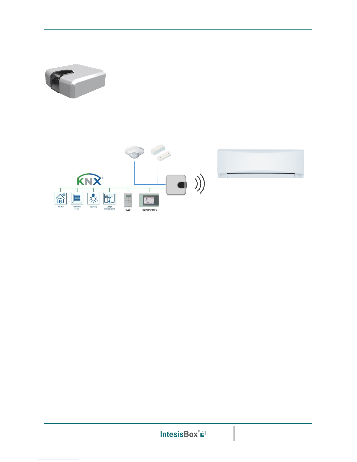
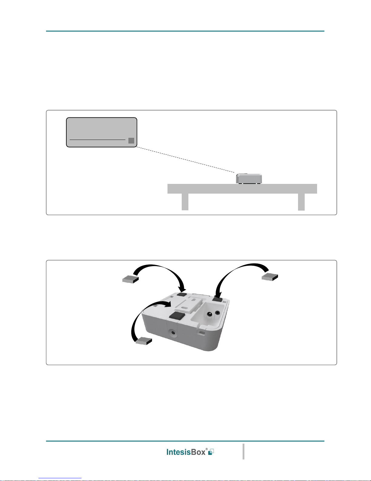
2 Quick setup
Figure 2.1 IS-IR-KNX-1i integration example
1. Check the interface location that best fits the installation (section 3.1)
2. Connect the interface to the KNX bus.
3. Download the ETS database for this product, import it and add it to the current ETS project.
4. Access the parameter section of the IntesisBox device. Notice that parameters for this interface are
configured through a specific plugin (section 5).
5. Select the communication objects to be used and other parameters. This step can be omitted if working
with the default objects and parameters.
6. Save the configuration file and download the application program.
7. Close the plugin and apply changes when asked.
8. Link the group address from the communication object of the KNX device with the communication object
inside the IntesisBox interface.
9. Download the ETS parameters as with any other standard KNX device.
Page 8
IntesisBox® KNX – IR Universal AC
User's manual r1.0 eng
© Intesis Software S.L.U. - All rights reserved
This information is subject to change without notice
IntesisBox® is a registered trademark of Intesis Software SLU
URL
Email
tel
http://www.intesisbox.com
info@intesisbox.com
+34 938047134
8 / 48
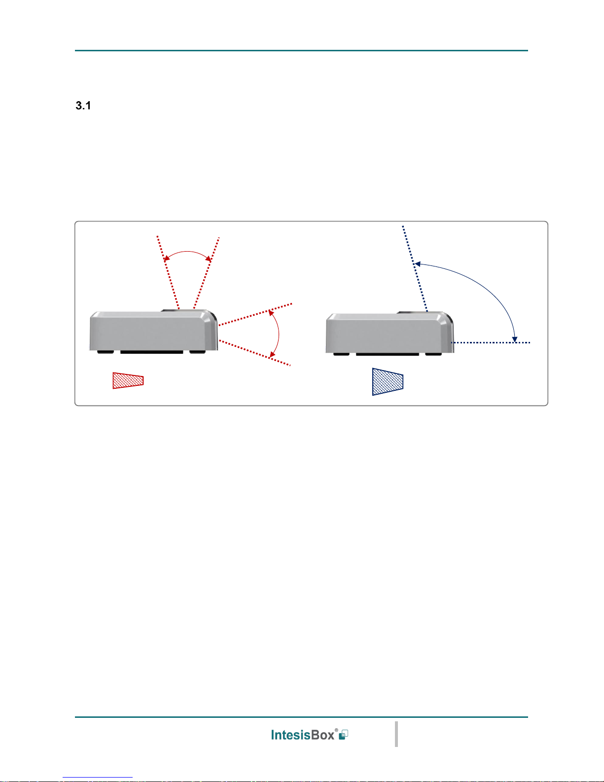
3 Device Installation
Location selection
Determining that the IntesisBox device will be working as expected in the installation location is an important
stage. In order to determine the best location for your IntesisBox device, use the Wireless Controller (the one
of your AC unit).
When selecting the installation location, please keep in mind that the IntesisBox device has 2 IR emitters and 1
IR receiver. The 2 emitters increase the installation possibilities allowing many different suitable positions for
the device location. On the other hand, the receiver offers the possibility to get the feedback from the IR wireless
remote controller so the KNX status objects can be updated with that feedback.
Figure 3.1 IR emitters and IR receiver location
IR reception area
IR transmission area
Page 9
IntesisBox® KNX – IR Universal AC
User's manual r1.0 eng
© Intesis Software S.L.U. - All rights reserved
This information is subject to change without notice
IntesisBox® is a registered trademark of Intesis Software SLU
URL
Email
tel
http://www.intesisbox.com
info@intesisbox.com
+34 938047134
9 / 48
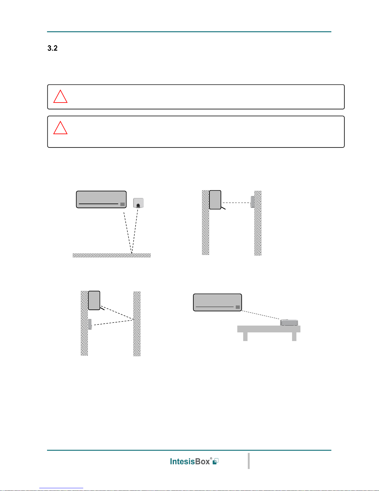
Connection to IR and location
There is no special requirement to match the IR receiver and the IntesisBox IS-IR-KNX-1i interface. Simply
select your model from the list present in the plugin. If your AC unit is not present, please check the compatibility
list as in section 7. You can find more information about the IR configuration in section 5.
IntesisBox IS-IR-KNX-1i can be installed in many different locations.
A) Side-by-side with the AC unit B) In front of the AC unit
C) Under the AC unit D) Desktop position
Figure 3.2 IR emitters and IR receiver location
Case A: Installed side-by-side with the AC unit. In that case, the signal will travel from the IntesisBox device to
the AC unit tacking advantage of the rebounds on the floor or other furniture present in the room.
D
IMPORTANT: Keep in mind that some furniture and materials (carpets, curtains, glass,
metal…) may affect on the IR communication.
NOTE: The IntesisBox device has 2 IR emitters pointing at 2 different locations. Considering
this and IR reflections, valid locations for the IntesisBox device may be many and very different
depending on each installation. Check section 3.1 for more information.
Page 10
IntesisBox® KNX – IR Universal AC
User's manual r1.0 eng
© Intesis Software S.L.U. - All rights reserved
This information is subject to change without notice
IntesisBox® is a registered trademark of Intesis Software SLU
URL
Email
tel
http://www.intesisbox.com
info@intesisbox.com
+34 938047134
10 / 48
Case B: Installed in front of the AC unit. In that case, the signal will travel from the IntesisBox device directly to
the AC unit.
Case C: Installed below the AC unit. In that case, the signal will travel from the IntesisBox device to the AC unit
tacking advantage of the rebounds on the wall in front of it or other furniture present in the room.
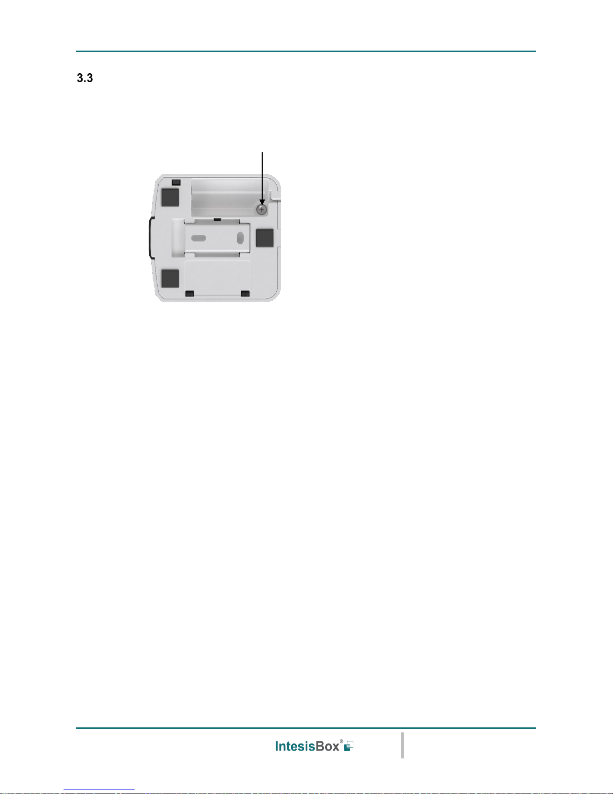
Case D: If you want to place the device on your desktop or any other horizontal surface, please consider the
sketch below. In this case, the signal will travel directly from the IntesisBox device to the AC unit.
Figure 3.3 Desktop mounted position
In order not to produce marks or scratches on the surface and also to improve the device stability, you can use
the rubber dumpers included in the package. Please, check Figure 3.4.
Figure 3.4 Rubber dumpers location
Page 11
IntesisBox® KNX – IR Universal AC
User's manual r1.0 eng
© Intesis Software S.L.U. - All rights reserved
This information is subject to change without notice
IntesisBox® is a registered trademark of Intesis Software SLU
URL
Email
tel
http://www.intesisbox.com
info@intesisbox.com
+34 938047134
11 / 48
Connection to KNX
IntesisBox device needs to be connected directly through a KNX TP-1 bus.
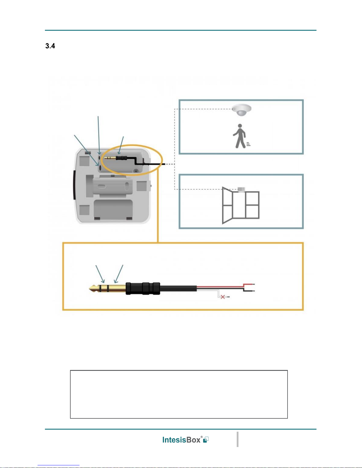
To get access to the KNX connector, remove the screw as seen in Figure 3.5.
Figure 3.5 Top lid release and KNX connection
Disconnect power of the KNX bus. Connect the IS-IR-KNX-1i to the KNX TP-1 (EIB) bus using the KNX standard
connector (red/grey) of the IS-IR-KNX-1i, respect polarity.
Reconnect power of the KNX bus, and mains power of the AC unit.
Setscrew
Page 12
IntesisBox® KNX – IR Universal AC
User's manual r1.0 eng
© Intesis Software S.L.U. - All rights reserved
This information is subject to change without notice
IntesisBox® is a registered trademark of Intesis Software SLU
URL
Email
tel
http://www.intesisbox.com
info@intesisbox.com
+34 938047134
12 / 48
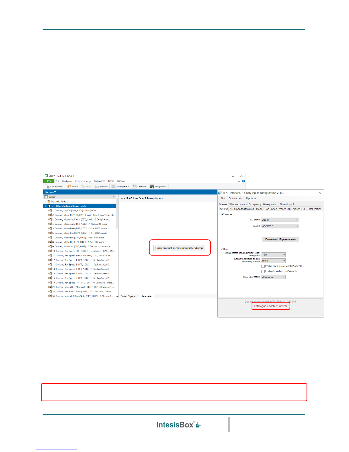
Binary Input connection
IntesisBox IS-IR-KNX.1i interface is equipped with a Binary Input from factory. To use the built-in binary input
in all the IR WIFI Controllers, a standard 3,5mm stereo jack connector is required.
Connections will be as in the image below.
Figure 3.6 Binary Input connection
IMPORTANT NOTE: Please, note that you can only connect a presence sensor or a window contact
simultaneously. Both sensors cannot work together at same time.
Before proceeding, please check the technical specification of the binary input below:
OPTION 1: PRESENCE DETECTOR
OPTION 2: WINDOW CONTACT
STEREO JACK
(3,5 mm)
BINARY INPUT
CONNECTOR
KNX INPUT
CONNECTOR
RIGHT
CHANNEL
COMMON
RIGHT
COMMON
LEFT (not used)
Potential free binary input
Signal cable length: 5m unshielded, may be extended up to 20m with twisted
Compliant with the following standards:
IEC61000-4-2: level 4 – 15kV (air discharge) - 8kV (contact discharge)
MIL STD 883E-Method 3015-7: class 3B
Page 13

IntesisBox® KNX – IR Universal AC
User's manual r1.0 eng
© Intesis Software S.L.U. - All rights reserved
This information is subject to change without notice
IntesisBox® is a registered trademark of Intesis Software SLU
URL
Email
tel
http://www.intesisbox.com
info@intesisbox.com
+34 938047134
13 / 48
Once you are sure your installation is compliant with the specifications, please check the presence sensor or
window contact you would like to use. Basically, sensors only need to be equipped with a potential free external
contact. No matter if the contact is NO (Normally Open) or NC (Normally closed) as you will be able to configure
the contact type (NO or NC) of your sensor in the settings of the Binary Input function (Go to Settings menu in
the IntesisBox WEB Site).
IMPORTANT NOTE: Please, note that IS-IR-KNX-1i interface will only react if the contact of your sensor is
opened or closed. In the case of the presence sensor, the installer needs to decide the specific settings of the
presence sensor to be applied. IntesisBox will be not responsible of the incorrect settings or incorrect
installations.
Recommendation: In some presence sensors or window contacts it is possible to setup a delay time to the
external contact. As you will see in this manual, IntesisBox Settings allow the user to setup a timer before
starting with the configured actions. Anyway, we recommend to setup a certain delay time in your presence
sensor or window contact to prevent continuous contact changes in a very short period of time.
Page 14

IntesisBox® KNX – IR Universal AC
User's manual r1.0 eng
© Intesis Software S.L.U. - All rights reserved
This information is subject to change without notice
IntesisBox® is a registered trademark of Intesis Software SLU
URL
Email
tel
http://www.intesisbox.com
info@intesisbox.com
+34 938047134
14 / 48
4 Configuration and setup
This is a fully compatible KNX device which must be configured and setup using standard KNX tool ETS.
Before starting with the configuration, please make sure that the binary inputs (if used) and the USB cable are
properly connected to the interface. Make sure as well, that the interface is connected to the KNX bus to allow
the proper download of the KNX programming.
In order to proceed with the configuration and set up, it is recommended to follow instructions next:
1. Download and install the latest version of the ETS data base (section 5).
2. Open the product’s plugin and make sure that the catalog is in its last available version (section 5).
3. Select your AC brand and model (section 5.1).
4. Download the infrared configuration to the IntesisBox pushing on the “Download IR parameters”.
NOTE: Check the current connection to the IntesisBox. Notice that in order to send the Infrared
configuration, you can use the standard KNX connection (the same used to program the device) or a
USB connection.
USB connection is faster than KNX connection. Notice that this is only available for the infrared
configuration settings.
5. Proceed with the rest of AC unit settings and other parameters.
6. Proceed with the KNX programming.
7. Download the programming to the interface as any other KNX device.
Page 15
IntesisBox® KNX – IR Universal AC
User's manual r1.0 eng
© Intesis Software S.L.U. - All rights reserved
This information is subject to change without notice
IntesisBox® is a registered trademark of Intesis Software SLU
URL
Email
tel
http://www.intesisbox.com
info@intesisbox.com
+34 938047134
15 / 48
5 ETS Parameters and Configuration
The IntesisBox IS-IR-KNX-1i interface is configured through ETS. General KNX parameters, such as the
physical address, group addresses or DPTs can be configured as usual using the ETS interface. For the specific
AC unit configuration and IR communication, the use of the specific plugin included in the ETS database is
required.
ETS database for this device can be downloaded from:
https://www.intesisbox.com/intesis/product/media/IS-IR-KNX-1i_ETS_database.zip
Please consult the README.txt file, located inside the downloaded zip file, to find instructions on how to install
the database.
Once the database is imported, the plugin can be accessed when editing parameters. To get access to
parameters edition, click on the Parameter tab, located in the project screen, and then press the specific
parameter dialog.
Figure 5.1 ETS Project managing and plugin screen
Remember that before start using the IntesisBox interface along with the AC unit, you need to set up at least
the brand and type of you AC unit. Check section 5.1 for more information about it.
IMPORTANT: Please, update the Catalogue before proceeding with the device configuration and programming.
The laptop where ETS is running shall have Internet connection to update the catalogue.
Page 16

IntesisBox® KNX – IR Universal AC
User's manual r1.0 eng
© Intesis Software S.L.U. - All rights reserved
This information is subject to change without notice
IntesisBox® is a registered trademark of Intesis Software SLU
URL
Email
tel
http://www.intesisbox.com
info@intesisbox.com
+34 938047134
16 / 48
General configuration
Inside this parameter’s dialog it is possible to activate or change the parameters shown below:
Figure 5.2 General parameters
5.1.1 AC brand
Use the dropdown menu to select the AC brand of the AC unit you want to control.
In case your AC unit brand is not present, please select the IS-IR-KNX-1i and contact our support department
for more information about the Model to select.
5.1.2 Model
Use the dropdown menu to select the AC brand of the AC unit you want to control.
In case your AC unit brand is not present in the AC brand list, please select the IS-IR-KNX-1i and contact our
support department for more information about the Model to select.
5.1.3 Delay before sending initial “Read” telegrams
This parameter sets the delay before the interface will send READ telegrams for the group addresses associated
on its Control_ objects on bus recovery or application reset/start-up. All Control_ objects with both Transmit (T)
and Update (U) flags enabled will send READs and their values will be updated with the response when
received.
Valid values go from 10 to 60 seconds. This is to give time enough to other KNX devices on the bus to start-up
before sending the READs.
AC brand
AC unit model
Page 17

IntesisBox® KNX – IR Universal AC
User's manual r1.0 eng
© Intesis Software S.L.U. - All rights reserved
This information is subject to change without notice
IntesisBox® is a registered trademark of Intesis Software SLU
URL
Email
tel
http://www.intesisbox.com
info@intesisbox.com
+34 938047134
17 / 48
5.1.4 Scene to execute on bus recovery / startup
This parameter executes a selected scene on bus recovery or startup, only if the selected scene has an enabled
preset or values previously saved from KNX bus (see Scene Configuration dialog). You can select any of the 5
available scenes.
5.1.5 Enable “lock control” objects
This parameter shows/hide the Control_ Lock Control Obj communication object which, depending on the sent
value, locks or unlocks ALL the Control_ communication objects except itself.
When a “1” value is sent to this communication object, the remote controller is locked. To be unlocked a “0”
value must be sent. The gateway remembers the last value received even if a KNX bus reset/failure happens.
Figure 5.3 Communication object detail
Important: If an initial scene is enabled and it has as Value for Remote Lock (unchanged) or unlocked,
this would unlock the remote controller because the initial scene has priority over the Control_ Lock Remote
Control communication object.
5.1.6 Enable func “Operation time objects”
This parameter shows/hides the Status_ Operating Hour Counter and Status_ Operating Second Counter
communication object which counts the number of operating hours for the IS-IR-KNX-1i.
Figure 5.4 Communication object detail
o If set to “no” the object will not be shown.
o If set to “yes” the Status_ Operation Hour Counter object will appear.
• This object can be read and sends its status every time an hour is counted. The gateway keeps that
count in memory and the status is sent also after a KNX bus reset/failure. Although this object is
marked as a Status_ object it also can be written to update the counter when needed. To reset the
counter should be written a “0” value.
Important: This object comes by default without the write (W) flag activated. If is necessary to write on it, this
flag must be activated.
Important: This object will also return its status, every time a value is written, only if it’s different from the
existing one.
Important: If the stored value is 0 hours, the gateway will not send the status to KNX.
Page 18

IntesisBox® KNX – IR Universal AC
User's manual r1.0 eng
© Intesis Software S.L.U. - All rights reserved
This information is subject to change without notice
IntesisBox® is a registered trademark of Intesis Software SLU
URL
Email
tel
http://www.intesisbox.com
info@intesisbox.com
+34 938047134
18 / 48
5.1.7 RGB LED mode
This parameter determines the working mode of the interface LED.
o If set to “Always off” the LED will always be off.
o If set to “Always on” the LED will always be on.
o If set to “Only on changes” the LED will always change when there is a change of value in any of the
active communication objects.
AC supported features
Select the AC features of your AC unit to match both: the AC unit features with the enabled communication
objects and parameters.
Please, select these parameters carefully, otherwise not expected behavior may occur.
Figure 5.5 AC supported features
Page 19

IntesisBox® KNX – IR Universal AC
User's manual r1.0 eng
© Intesis Software S.L.U. - All rights reserved
This information is subject to change without notice
IntesisBox® is a registered trademark of Intesis Software SLU
URL
Email
tel
http://www.intesisbox.com
info@intesisbox.com
+34 938047134
19 / 48
Mode
All the parameters in this section are related with the different mode properties and communication objects.
The byte-type communication object for Mode works with the DTP_20.105. Auto mode will be enabled with a
“0” value, Heat mode with a “1” value, Cool mode with a “3” value, Fan mode with a “9” value and Dry mode
with a “14” value.
Figure 5.6 AC mode additional communication objects
5.3.1 Enable use of bit-type Mode objects (for control)
This parameter shows/hides the bit-type Control_ Mode objects.
Figure 5.7 Communication object detail
o If set to “no” the objects will not be shown.
o If set to “yes” the Control_ Mode objects for Auto, Heat, Cool, Fan and Dry will appear. To activate a mode
by using these objects a “1” value has to be sent.
5.3.2 Enable use of bit-type Mode objects (for status)
This parameter shows/hides the bit-type Status_ Mode objects.
Figure 5.8 Communication object detail
Page 20

IntesisBox® KNX – IR Universal AC
User's manual r1.0 eng
© Intesis Software S.L.U. - All rights reserved
This information is subject to change without notice
IntesisBox® is a registered trademark of Intesis Software SLU
URL
Email
tel
http://www.intesisbox.com
info@intesisbox.com
+34 938047134
20 / 48
o If set to “no” the objects will not be shown.
o If set to “yes” the Status_ Mode objects for Auto, Heat, Cool, Fan and Dry will appear. When enabled, a
mode will return a “1” through its bit-type object.
5.3.3 Enable use of + / - object for Mode
This parameter shows/hides the Control_ Mode +/- communication object which lets change the indoor unit
mode by using two different datapoint types.
o If set to “no” the object will not be shown.
o If set to “yes” the Control_ Mode +/- object and a new parameter will appear.
➢ DPT type for +/- Mode Object
This parameter lets choose between the datapoints 0-Up / 1-Down [DPT_1.008] and 0-Decrease / 1-
Increase [DPT_1.007] for the Control_ Mode +/- object.
The sequence followed when using this object is shown below:
5.3.4 Enable use of Text object for Mode
This parameter shows/hides the Status_ Mode Text communication object.
o If set to “no” the object will not be shown.
o If set to “yes” the Status_ Mode Text object will appear.
▪ Up / Increase
▪ Down / Decrease
DRY
AUTO
HEAT
COOL
FAN
Page 21

IntesisBox® KNX – IR Universal AC
User's manual r1.0 eng
© Intesis Software S.L.U. - All rights reserved
This information is subject to change without notice
IntesisBox® is a registered trademark of Intesis Software SLU
URL
Email
tel
http://www.intesisbox.com
info@intesisbox.com
+34 938047134
21 / 48
Fan Speed
All the parameters in this section are related with the Fan Speed properties and communication objects.
Figure 5.9 Fan Speed parameters
5.4.1 DPT object type for fan speed
With this parameter is possible to change de DPT for the Control_ Fan Speed and Status_ Fan Speed bytetype communication objects. Datapoints Scaling (DPT_5.001) and Enumerated (DPT_5.010) can be selected.
o When “Enumerated [DPT 5.010]” is selected, Control_ Fan Speed and Status_ Fan Speed communication
objects for this DPT will appear. Also, depending on the number of fan speeds selected, these objects will
be different.
The first fan speed will be selected if a “1” is sent to the Control_ object. The second fan speed will be
selected sending a “2” and so on.
The Status_ object will always return the value for the fan speed selected.
Important: In both cases if a “0” value is sent to the Control_ object, the minimum fan speed will be
selected. If a value bigger than “2” (in case of 2 speeds) or bigger than “3” (in case of 3 fan speeds)
is sent to the Control_ object, then the maximum fan speed will be selected.
o When “Scaling [DPT 5.001]” is selected, Control_ Fan Speed and Status_ Fan Speed communication
objects for this DPT will appear. Also, depending on the number of fan speeds selected, these objects will
be different.
Page 22

IntesisBox® KNX – IR Universal AC
User's manual r1.0 eng
© Intesis Software S.L.U. - All rights reserved
This information is subject to change without notice
IntesisBox® is a registered trademark of Intesis Software SLU
URL
Email
tel
http://www.intesisbox.com
info@intesisbox.com
+34 938047134
22 / 48
The formula used to calculate the value to be set in the Control object is ‘100*(n+0,5)/N %’, where n is the
current fan speed and N the maximum number of fan speeds.
On the other hand, the formula to calculate the status to be read according to the current value is ‘100*n/N’,
where n is the current fan speed and N the maximum number of fan speeds.
Check this example with 3 fan speeds:
When a value between 0% and 49% is sent to the Control_ object the first fan speed will be selected.
When a value between 50% and 83% is sent to the Control_ object, the second speed will be selected.
When a value between 84% and 100% is sent to the Control_ object, the third speed will be selected.
The Status_ object will return a 33% when the first speed is selected, a 67% for the second one and a 100%
for the third one.
5.4.2 Enable use of bit-type Fan Speed objects (for Control)
This parameter shows/hides the bit-type Control_ Fan Speed objects.
o If set to “no” the objects will not be shown.
o If set to “yes” the Control_ Fan Speed objects for Speed 1, Speed 2 and Speed 3 (if available) will appear.
To activate a Fan Speed by using these objects a “1” value has to be sent.
5.4.3 Enable use of bit-type Fan Speed objects (for Status)
This parameter shows/hides the bit-type Status_ Fan Speed objects.
Fan Speed 1
Fan Speed 3
100%
Status_
0%
83%
50%
Control_
Control_
Status_
33%
67%
Fan Speed 2
Control_
Status_
Page 23

IntesisBox® KNX – IR Universal AC
User's manual r1.0 eng
© Intesis Software S.L.U. - All rights reserved
This information is subject to change without notice
IntesisBox® is a registered trademark of Intesis Software SLU
URL
Email
tel
http://www.intesisbox.com
info@intesisbox.com
+34 938047134
23 / 48
o If set to “no” the objects will not be shown.
o If set to “yes” the Status_ Fan Speed objects for Speed 1, Speed 2 and Speed 3 (if available) will appear.
When a Fan Speed is enabled, a “1” value is returned through its bit-type object.
5.4.4 Enable use of +/- object for Fan Speed
This parameter shows/hides the Control_ Fan Speed +/- communication object which lets you
increase/decrease the indoor unit fan speed by using two different datapoint types.
o If set to “no” the object will not be shown.
o If set to “yes” the Control_ Fan Speed +/- object.
➢ DPT type for +/- Fan Speed Object
This parameter lets choose between the datapoints 0-Up / 1-Down [DPT_1.008] and 0-Decrease / 1-
Increase [DPT_1.007] for the Control_ Fan Speed +/- object.
➢ Roll-over Speed at upper/lower limit
This parameter lets choose if roll-over will be enabled (“yes”) or disabled (“no”) for the Control_ Fan
Speed +/- object.
5.4.5 Enable use of Text object for Fan Speed
This parameter shows/hides the Status_ Fan Speed Text communication object.
▪ Up / Increase
▪ Down / Decrease
Fan Speed 3
Fan Speed 1
Fan Speed 2
Only if Roll-over is enabled
Only if Roll-over is enabled
Page 24

IntesisBox® KNX – IR Universal AC
User's manual r1.0 eng
© Intesis Software S.L.U. - All rights reserved
This information is subject to change without notice
IntesisBox® is a registered trademark of Intesis Software SLU
URL
Email
tel
http://www.intesisbox.com
info@intesisbox.com
+34 938047134
24 / 48
o If set to “no” the object will not be shown.
o If set to “yes” the Status_ Fan Speed Text object will appear.
Up-Down vanes configuration dialog
All the parameters in this section are related with the Vane Up-Down properties and communication objects.
5.5.1 DPT object type for Vane Up-Down
With this parameter is possible to change de DPT for the Control_ Vane Up-Down and Status_ Vane Up-Down
byte-type communication objects. Datapoints Scaling (DPT_5.001) and Enumerated (DPT_5.010) can be
selected.
o When “Enumerated [DPT 5.010]” is selected, Control_ Vane Up-Down and Status_ Vane Up-Down
communication objects for this DPT will appear.
To choose a vane position, values from “1” to “N” can be sent to the Control_ object. Each value will
correspond to the position (i.e. Value “3” = Position 3).
The Status_ object will always return the value for the vane position selected.
Important: If a “0” value is sent to the Control_ object, the Position 1 will be selected. If a value bigger
than “N” is sent to the Control_ object, then the Position N will be selected.
o When “Scaling [DPT 5.001]” is selected, Control_ Vane Up-Down and Status_ Vane Up-Down
communication objects for this DPT will appear.
The formula used to calculate the value to be set in the Control object is ‘100*(n+0,5)/N %’, where n is the
current fan speed and N the maximum number of fan speeds.
On the other hand, the formula to calculate the status to be read according to the current value is ‘100*n/N’,
where n is the current fan speed and N the maximum number of fan speeds.
Check the example with 5 positions:
When a value between 0% and 29% is sent to the Control_ object the first vane position will be selected.
When a value between 30% and 49% is sent to the Control_ object, the second vane position will be
selected.
When a value between 50% and 69% is sent to the Control_ object, the third vane position will be selected.
When a value between 70% and 89% is sent to the Control_ object, the fourth vane position will be selected.
Page 25

IntesisBox® KNX – IR Universal AC
User's manual r1.0 eng
© Intesis Software S.L.U. - All rights reserved
This information is subject to change without notice
IntesisBox® is a registered trademark of Intesis Software SLU
URL
Email
tel
http://www.intesisbox.com
info@intesisbox.com
+34 938047134
25 / 48
When a value between 90% and 100% is sent to the Control_ object, the fifth vane position will be selected.
The Status_ object will return a 20% for the first vane position, a 40% for the second one, a 60% for the
third one, an 80% for the fourth one and a 100% for the fifth and last one.
5.5.2 Enable use of bit-type Vane U-D objects (for Control)
This parameter shows/hides the bit-type Control_ Vane Up-Down objects.
o If set to “no” the objects will not be shown.
o If set to “yes” the Control_ Vane Up-Down objects for each Position (1 to 5) will appear. To activate a Vane
Position by using these objects, a “1” value has to be sent.
5.5.3 Enable use of bit-type Vane U-D objects (for Status)
This parameter shows/hides the bit-type Status_ Vane Up-Down objects.
o If set to “no” the objects will not be shown.
o If set to “yes” the Status_ Vane Up-Down objects for each Position (1 to N) will appear. When a Vane
Position is enabled, a “1” value is returned through its bit-type object.
Pos. 1
Pos. 3
100%
Status_
0%
90%
50%
Control_
Control_
Status_
30%
70%
Pos. 2
Control_
Status_
Pos. 4
Pos. 5
Control_
Control_
20%
40%
60%
80%
Status_
Status_
Page 26

IntesisBox® KNX – IR Universal AC
User's manual r1.0 eng
© Intesis Software S.L.U. - All rights reserved
This information is subject to change without notice
IntesisBox® is a registered trademark of Intesis Software SLU
URL
Email
tel
http://www.intesisbox.com
info@intesisbox.com
+34 938047134
26 / 48
5.5.4 Enable use of +/- obj for Vane Up-Down
This parameter shows/hides the Control_ Vane Up-Down +/- communication object which lets you change the
indoor unit vane position by using two different datapoint types.
o If set to “no” the object will not be shown.
o If set to “yes” the Control_ Vane Up-Down +/- object.
➢ DPT type for +/- Vane Up-Down obj
This parameter lets choose between the datapoints 0-Up / 1-Down [DPT_1.008] and 0-Decrease / 1-
Increase [DPT_1.007] for the Control_ Vane Up-Down +/- object.
➢ Rollover Vane at upper/lower limit
This parameter lets choose if roll-over will be enabled (“yes”) or disabled (“no”) for the Vane Up-Down
+/- object.
5.5.5 Enable use of Text object for Vane U-D
This parameter shows/hides the Status_ Vane Up-Down Text communication object.
o If set to “no” the object will not be shown.
o If set to “yes” the Status_ Vane Up-Down Text object will appear.
▪ Up / Increase
▪ Down / Decrease
Pos. 3
Pos. 1
Pos. 2
Only if Roll-over is enabled
Only if Roll-over is enabled
Pos. 5
Pos. 4
SWING
Page 27

IntesisBox® KNX – IR Universal AC
User's manual r1.0 eng
© Intesis Software S.L.U. - All rights reserved
This information is subject to change without notice
IntesisBox® is a registered trademark of Intesis Software SLU
URL
Email
tel
http://www.intesisbox.com
info@intesisbox.com
+34 938047134
27 / 48
Left-Right vanes configuration dialog
All the parameters in this section are related with the Vane Up-Down properties and communication objects.
5.6.1 DPT object type for Vane Left-Right
With this parameter is possible to change de DPT for the Control_ Vane Left-Right and Status_ Vane Left-Right
byte-type communication objects. Datapoints Scaling (DPT_5.001) and Enumerated (DPT_5.010) can be
selected.
o When “Enumerated [DPT 5.010]” is selected, Control_ Vane Left-Right and Status_ Vane Left-Right
communication objects for this DPT will appear.
To choose a vane position, values from “1” to “N” can be sent to the Control_ object. Each value will
correspond to the position (i.e. Value “3” = Position 3).
The Status_ object will always return the value for the vane position selected.
Important: If a “0” value is sent to the Control_ object, the Position 1 will be selected. If a value bigger
than “N” is sent to the Control_ object, then the Position N will be selected.
o When “Scaling [DPT 5.001]” is selected, Control_ Vane Up-Down and Status_ Vane Up-Down
communication objects for this DPT will appear.
The formula used to calculate the value to be set in the Control object is ‘100*(n+0,5)/N %’, where n is the
current fan speed and N the maximum number of fan speeds.
On the other hand, the formula to calculate the status to be read according to the current value is ‘100*n/N’,
where n is the current fan speed and N the maximum number of fan speeds.
Check the example with 5 positions:
When a value between 0% and 29% is sent to the Control_ object the first vane position will be selected.
When a value between 30% and 49% is sent to the Control_ object, the second vane position will be
selected.
When a value between 50% and 69% is sent to the Control_ object, the third vane position will be selected.
When a value between 70% and 89% is sent to the Control_ object, the fourth vane position will be selected.
When a value between 90% and 100% is sent to the Control_ object, the fifth vane position will be selected.
The Status_ object will return a 20% for the first vane position, a 40% for the second one, a 60% for the
third one, an 80% for the fourth one and a 100% for the fifth and last one.
Page 28

IntesisBox® KNX – IR Universal AC
User's manual r1.0 eng
© Intesis Software S.L.U. - All rights reserved
This information is subject to change without notice
IntesisBox® is a registered trademark of Intesis Software SLU
URL
Email
tel
http://www.intesisbox.com
info@intesisbox.com
+34 938047134
28 / 48
5.6.2 Enable use of bit-type Vane L-R objects (for Control)
This parameter shows/hides the bit-type Control_ Vane Left-Right objects.
o If set to “no” the objects will not be shown.
o If set to “yes” the Control_ Vane Up-Down objects for each Position (1 to N) will appear. To activate a Vane
Position by using these objects, a “1” value has to be sent.
5.6.3 Enable use of bit-type Vane U-D objects (for Status)
This parameter shows/hides the bit-type Status_ Vane Up-Down objects.
o If set to “no” the objects will not be shown.
o If set to “yes” the Status_ Vane Up-Down objects for each Position (1 to N) will appear. When a Vane
Position is enabled, a “1” value is returned through its bit-type object.
Pos. 1
Pos. 3
100%
Status_
0%
90%
50%
Control_
Control_
Status_
30%
70%
Pos. 2
Control_
Status_
Pos. 4
Pos. 5
Control_
Control_
20%
40%
60%
80%
Status_
Status_
Page 29

IntesisBox® KNX – IR Universal AC
User's manual r1.0 eng
© Intesis Software S.L.U. - All rights reserved
This information is subject to change without notice
IntesisBox® is a registered trademark of Intesis Software SLU
URL
Email
tel
http://www.intesisbox.com
info@intesisbox.com
+34 938047134
29 / 48
5.6.4 Enable use of +/- obj for Vane Left-Right
This parameter shows/hides the Control_ Vane Left-Right +/- communication object which lets you change the
indoor unit vane position by using two different datapoint types.
o If set to “no” the object will not be shown.
o If set to “yes” the Control_ Vane Left-Right +/- object.
➢ DPT type for +/- Vane Left-Right obj
This parameter lets choose between the datapoints 0-Up / 1-Down [DPT_1.008] and 0-Decrease / 1-
Increase [DPT_1.007] for the Control_ Vane Left-Right +/- object.
➢ Rollover Vane at upper/lower limit
This parameter lets choose if roll-over will be enabled (“yes”) or disabled (“no”) for the Vane Up-Down
+/- object.
5.6.5 Enable use of Text object for Vane U-D
This parameter shows/hides the Status_ Vane Up-Down Text communication object.
o If set to “no” the object will not be shown.
o If set to “yes” the Status_ Vane Up-Down Text object will appear.
▪ Up / Increase
▪ Down / Decrease
Pos. 3
Pos. 1
Pos. 2
Only if Roll-over is enabled
Only if Roll-over is enabled
Pos. 5
Pos. 4
SWING
Page 30

IntesisBox® KNX – IR Universal AC
User's manual r1.0 eng
© Intesis Software S.L.U. - All rights reserved
This information is subject to change without notice
IntesisBox® is a registered trademark of Intesis Software SLU
URL
Email
tel
http://www.intesisbox.com
info@intesisbox.com
+34 938047134
30 / 48
Temperature configuration dialog
All the parameters in this section are related with the Temperature properties and communication objects.
Figure 5.10 Tempeature settings
5.7.1 Set Point - Enable use of +/- obj for Setp Temp
This parameter shows/hides the Control_ Setpoint Temp +/- communication object which lets you change the
indoor unit setpoint temperature by using two different datapoint types.
o If set to “no” the object will not be shown.
o If set to “yes” the Control_ Setpoint Temp +/- object.
➢ DPT type for +/- Setp Temp object
This parameter lets choose between the datapoints 0-Up / 1-Down [DPT_1.008] and 0-Decrease / 1-
Increase [DPT_1.007] for the Control_ Setpoint Temp +/- object.
▪ Up / Increase
▪ Down / Decrease
…
16ºC
17ºC
32ºC
31ºC
(Upper limit)
(Lower limit)
Page 31

IntesisBox® KNX – IR Universal AC
User's manual r1.0 eng
© Intesis Software S.L.U. - All rights reserved
This information is subject to change without notice
IntesisBox® is a registered trademark of Intesis Software SLU
URL
Email
tel
http://www.intesisbox.com
info@intesisbox.com
+34 938047134
31 / 48
5.7.2 Set Point - Enable limits on Control_ Setpoint obj
This parameter enables to define temperature limits for the Control_ Setpoint Temperature object.
o If set to “no” the setpoint temperature limits for the Control_ Setpoint Temperature object will be the default:
16ºC for the lower limit and 32ºC for the upper limit.
o If set to “yes” it is possible to define temperature limits for the Control_ Setpoint Temperature object.
➢ Control_ Set Temp Lower limit (ºC)
This parameter lets to define the lower limit for the setpoint temperature.
➢ Control_ Set Temp Upper limit (ºC)
This parameter lets to define the upper limit for the setpoint temperature.
Important: If a setpoint temperature above the upper defined limit (or below the lower defined limit) is sent
through the Control_ Setpoint Temperature object, it will be ALWAYS applied the limit defined.
Important: When limits are enabled, any setpoint temperature sent to the AC (even through scenes, special
modes, etc.) will be limited.
5.7.3 Set Point - Periodic sending time
This parameter lets you change the interval of time (in seconds, from 0 to 255) at the end of which the AC
setpoint temperature is sent to the KNX bus. For a “0” value, the AC setpoint temperature will ONLY be sent
on change. The AC setpoint temperature is sent through the communication object Status_ AC Setpoint Temp.
5.7.4 Ambient - Transmission of “Status_ AC Ret Temp”
This parameter lets to you choose if the AC return temperature will be sent “only cyclically”, “only on change”
or “cyclically and on change”. The AC return temperature is sent through the communication object Status_
AC Return Temp.
5.7.5 Ambient - Periodic sending time
This parameter will only be available for the “only cylically” and “cyclically and on change” options, and lets
you change the interval of time (in seconds, from 1 to 255) at the end of which the AC return temperature is
sent to the KNX bus.
Page 32

IntesisBox® KNX – IR Universal AC
User's manual r1.0 eng
© Intesis Software S.L.U. - All rights reserved
This information is subject to change without notice
IntesisBox® is a registered trademark of Intesis Software SLU
URL
Email
tel
http://www.intesisbox.com
info@intesisbox.com
+34 938047134
32 / 48
Scene Configuration dialog
All the parameters in this section are related with the Scene properties and communication objects. A scene
contains values of: On/Off, Mode, Fan speed, Vane position and Setpoint Temperature.
Figure 5.11 Scene configuration settings
5.8.1 Enable use of scenes
This parameter shows/hides the scene configuration parameters and communication objects.
o If set to “no” the scene parameters and communication objects will not be shown.
o If set to “yes” the scene parameters and communication objects will be shown. To execute a scene through
the byte-type object, a value from “0” to “4” has to be sent, correponding each one to a different scene (i.e.
“0” = Scene 1;… “4” = Scene 5).
5.8.2 Scenes can be saved from KNX
This parameter shows/hides the Control_ Save/Exec Scene and all the Control_ Save Scene (if enabled)
communication objects.
Page 33

IntesisBox® KNX – IR Universal AC
User's manual r1.0 eng
© Intesis Software S.L.U. - All rights reserved
This information is subject to change without notice
IntesisBox® is a registered trademark of Intesis Software SLU
URL
Email
tel
http://www.intesisbox.com
info@intesisbox.com
+34 938047134
33 / 48
o If set to “no” the communication objects will not be shown.
o If set to “yes” the communication objects and a new parameter will appear. To store a scene through the
byte-type object, a value from “128” to “132” has to be sent to the object, correponding each one to a
different scene (i.e. “128” = Scene 1;… “132” = Scene 5).
➢ Enable use of bit objects for storing scenes (from bus)
If set to “no” the objects will not be shown.
If set to “yes” the Control_ Store Scene objects for storing scenes will appear. To store a scene by
using these objects, a “1” value has to be sent to the scene’s object we want to store (i.e. to store scene
4, a “1” has to be sent to the Control_ Store Scene 4 object).
5.8.3 Enable use of bit-field objects for save
This parameter shows/hides the Control_ Execute Scene bit-type communication objects.
o If set to “no” the communication objects will not be shown.
o If set to “yes” the communication objects will appear. To execute a scene by using these objects, a “1”
value has to be sent to the scene’s object we want to execute (i.e. to execute scene 4, a “1” has to be sent
to the Control_ Execute Scene 4 object).
5.8.4 Enable use of bit-field objects for execute
This parameter shows/hides the Control_ Execute Scene bit-type communication objects.
Page 34

IntesisBox® KNX – IR Universal AC
User's manual r1.0 eng
© Intesis Software S.L.U. - All rights reserved
This information is subject to change without notice
IntesisBox® is a registered trademark of Intesis Software SLU
URL
Email
tel
http://www.intesisbox.com
info@intesisbox.com
+34 938047134
34 / 48
o If set to “no” the communication objects will not be shown.
o If set to “yes” the communication objects will appear. To execute a scene by using these objects, a “1”
value has to be sent to the scene’s object we want to execute (i.e. to execute scene 4, a “1” has to be sent
to the Control_ Execute Scene 4 object).
5.8.5 Scene “x” preset
This parameter lets you define a preset for a scene (the following description is valid for all the scenes).
o If set to “no” the preset for the scene “x” will be disabled.
o If set to “yes” the preset will be enabled. When a scene is executed the values configured in the preset will
be aplied.
Important: If a scene’s preset is enabled, will not be possible to modify (store) the scene from the KNX
bus.
➢ Scene “x” / Value for On-Off
This parameter lets you choose the power of the indoor unit when the scene is executed. The following
options are available: “ON”, “OFF” or “(unchanged)”.
➢ Scene “x” / Value for Mode
This parameter lets you choose the mode of the indoor unit when the scene is executed. The following
options are available: “AUTO”, “HEAT”, “COOL”, “FAN”, “DRY”, or “(unchanged)”.
➢ Scene “x” / Value for Fan Speed
This parameter lets you choose the fan speed of the indoor unit when the scene is executed. The
following options are available: “SPEED 1”, “SPEED 2”… “SPEED N”, or “(unchanged)”.
➢ Scene “x” / Value for Vane Up-Down
This parameter lets you choose the vane position of the indoor unit when the scene is executed. The
following options are available: “POSITION 1”, “POSITION 2”… “POSITION N”, “SWIRL”, “SWING”
or “(unchanged)”.
➢ Scene “x” / Value for Vane Left-Right
This parameter lets you choose the vane position of the indoor unit when the scene is executed. The
following options are available: “POSITION 1”, “POSITION 2”… “POSITION N”, “SWIRL”, “SWING”
or “(unchanged)”.
➢ Scene “x” / Value for Setp Temp (ºC)
This parameter lets you choose the setpoint temperature of the indoor unit when the scene is executed.
The following options are available: from “16ºC” to “32ºC” (both included), or “(unchanged)”.
Page 35

IntesisBox® KNX – IR Universal AC
User's manual r1.0 eng
© Intesis Software S.L.U. - All rights reserved
This information is subject to change without notice
IntesisBox® is a registered trademark of Intesis Software SLU
URL
Email
tel
http://www.intesisbox.com
info@intesisbox.com
+34 938047134
35 / 48
Important: If any preset value is configured as “(unchanged)”, the execution of this scene will not
change current status of this feature in the AC unit.
Important: When a scene is executed, Status_ Current Scene object shows the number of this scene.
Any change in previous items does Status_ Current Scene show “No Scene”. Only changes on items
marked as “(unchanged)” will not disable current scene.
Enable use of Open Window
This parameter shows/hides the Control_ Window Contact Input communication object which lets you Start/Stop
a timeout to switch off the indoor unit.
o If set to “no” the object will not be shown.
o If set to “yes” the Control_ Window Contact Input object will appear. If a “1” value is sent to this object,
and the indoor unit is already turned on, the switch-off timeout will begin. If a “0” value is sent to this object,
the switch-off timeout will stop.
➢ Input Object
This parameter lets you choose between the datapoints 0-Open / 1-Closed Window [DPT_1.009] and
0-Stop / 1-Start Timeout [DPT_1.010] for the Control_ Switch Off Timeout.
➢ Timeout (min)
This parameter lets you select how much time (in minutes) to wait before switching off the indoor unit.
➢ Reload last Value
If set to “no”, once the switch-off timeout is stopped, any value will be reloaded.
If set to “yes”, once the switch-off timeout is stopped, the last On/Off value sent will be reloaded.
• If a “1” value is sent to the Control_ Window Contact Input object after the timeout period, the
indoor unit will turn on.
Page 36

IntesisBox® KNX – IR Universal AC
User's manual r1.0 eng
© Intesis Software S.L.U. - All rights reserved
This information is subject to change without notice
IntesisBox® is a registered trademark of Intesis Software SLU
URL
Email
tel
http://www.intesisbox.com
info@intesisbox.com
+34 938047134
36 / 48
• If a “0” value is sent to the Control_ Switch Off Timeout after the timeout period, no action will
be performed.
➢ Lock ON when Open
If set to “no”, On/Off commands while the window is open will be accepted.
• If a “1” value is sent to the Control_ Switch Off Timeout object the switch-off timeout period will
begin again.
• If a “0” value is sent to the Control_ Switch Off Timeout object, no action will be performed.
If set to “yes”, On/Off commands, while the window is open, will be saved (but not applied). These
commands will be used in the next parameter if set to “yes”.
Enable use of Occupancy function
This parameter shows/hides the Control_ Occupancy Input communication object which lets you apply different
parameters to the indoor unit depending on the presence/no presence in the room.
o If set to “no” the object will not be shown.
o If set to “yes” the Control_ Occupancy object and new parameters will appear. If a “1” value is sent to this
object (no room occupancy), the timeout will begin. If a “0” value is sent to this object, the timeout will stop.
Figure 4.33 Parameter detail
Page 37

IntesisBox® KNX – IR Universal AC
User's manual r1.0 eng
© Intesis Software S.L.U. - All rights reserved
This information is subject to change without notice
IntesisBox® is a registered trademark of Intesis Software SLU
URL
Email
tel
http://www.intesisbox.com
info@intesisbox.com
+34 938047134
37 / 48
➢ Timeout to apply action (minutes)
This parameter lets you choose how much time to wait (in minutes) before executing the action specified
in the next parameter (“Action after timeout elapsed”).
➢ Action
When Switch Off AC is selected, once the timeout has elapsed, the indoor unit will be turned off.
When Apply Preset Delta is selected, once the timeout has elapsed, a delta temperature will be applied
in order to save energy (decreasing the setpoint when in Heat mode, or increasing the setpoint when in
Cool mode). Also new parameters will appear.
➢ Temp delta decrease (HEAT) or increase (COOL) (ºC)
This parameter lets configure the delta temperature (increase or decrease) that will be applied
when the timeout has elapsed.
Important: When there is occupancy again after the application of a delta, the same delta will
be applied inversely. (i.e. In a room with AC in cool mode and 25ºC setpoint temperature, a
+2ºC delta is applied after the occupancy timeout, setting the setpoint at 27ºC because there
is no occupancy in the room. If the setpoint is raised to 29ºC during that period, when the room
is occupied again, a -2ºC delta will be applied and the final setpoint temperature will then be
27ºC).
➢ Second Action
If set to “no” nothing will be applied.
If set to “yes”, a new timeout will be enabled and two new parameters will appear.
➢ Timeout (2nd)
This parameter lets you choose how much time to wait (in minutes) before executing the action specified
in the next parameter (“Action after timeout elapsed”).
➢ Action (2nd)
When Switch-Off is selected, once the timeout has elapsed, the indoor unit will turn off.
When Apply Preset Delta is selected, once the timeout configured is extinguished, a delta temperature
will be applied (decreasing the setpoint when in Heat mode, or increasing the setpoint when in Cool
mode). Also new parameters will appear.
➢ Temp delta decrease (HEAT) or increase (COOL) (ºC)
This parameter lets configure the delta temperature that will be applied when the timeout is
extinguished.
Important: When there is occupancy again after the application of a delta, the same delta will
be applied inversely as explained above.
Page 38

IntesisBox® KNX – IR Universal AC
User's manual r1.0 eng
© Intesis Software S.L.U. - All rights reserved
This information is subject to change without notice
IntesisBox® is a registered trademark of Intesis Software SLU
URL
Email
tel
http://www.intesisbox.com
info@intesisbox.com
+34 938047134
38 / 48
➢ Reload last On/Off value when Occupied
If set to “no”, once the switch-off timeout has elapsed, any value will be reloaded.
If set to “yes”, once the switch-off timeout has elapsed, the last On/Off value will be reloaded.
• If a “1” value is sent to the Control_ Occupancy object after the timeout period, the indoor unit
will turn on.
• If a “0” value is sent to the Control_ Occupancy after the timeout period no action will be
performed.
➢ Lock ON when occupied
If set to “no”, On/Off commands while the room is occupied will be accepted.
• If a “1” value is sent to the Control_ Switch Off Timeout object the switch-off timeout period will
begin again.
• If a “0” value is sent to the Control_ Switch Off Timeout object, no action will be performed.
If set to “yes”, On/Off commands, while the window is open, will be saved (but not applied). These
commands will be used in the next parameter if set to “yes”.
Binary Input “x” configuration dialogs
All the parameters in this section are related with the binary inputs properties and communication objects.
5.11.1 Enable use of Input “x”
This parameter enables the use of the Input “x”.
o If set to “no” the objects will not be shown.
o If set to “yes” the Status_ Inx object(s) and new parameters will appear.
Page 39

IntesisBox® KNX – IR Universal AC
User's manual r1.0 eng
© Intesis Software S.L.U. - All rights reserved
This information is subject to change without notice
IntesisBox® is a registered trademark of Intesis Software SLU
URL
Email
tel
http://www.intesisbox.com
info@intesisbox.com
+34 938047134
39 / 48
5.11.2 Contact type
This parameter lets choose the behavior that will have the binary input depending on if the contact is normally
open or normally closed.
o There are two possible options to configure the contact type: “NO: Normally Open” and “NC: Normally
Closed”.
5.11.3 Debounce time
This parameter lets choose a debounce time (in milliseconds) that will be applied to the contact.
5.11.4 Disabling function
This parameter shows/hides the Control_ Disable Input x communication object which will let disable/enable the
input x.
o If set to “no” any object will be shown.
o When “DPT 1.003: 0-Disable; 1-Enable” is selected, the input can be disabled using the value “0” and
enabled using the value “1”.
o When “DPT 1.002: 1-True (Disable); 0-False (Enable)” is selected, the input can be disabled using the
value “1” and enabled using the value “0”.
5.11.5 Function
This parameter lets choose the function that will have the binary input. There are 3 different functions available:
Occupancy (internal), On/Off and Window Contact (internal).
o When “Occupancy” is selected, the binary input “x” will have the same behavior as configured in the
parameter “Occupanys” (section 5.10).
o When “On/Off” is selected, the AC unit will turn off when the binary inpyt “x” is active.
o When “Window Contact (internal)” is selected, the binary input “x” will have the same behavior as
configured in the parameter “Window Contact” (section 5.9).
Page 40

IntesisBox® KNX – IR Universal AC
User's manual r1.0 eng
© Intesis Software S.L.U. - All rights reserved
This information is subject to change without notice
IntesisBox® is a registered trademark of Intesis Software SLU
URL
Email
tel
http://www.intesisbox.com
info@intesisbox.com
+34 938047134
40 / 48
6 Electrical and Mechanical features
Enclosure
ABS (V-0). 2,1 mm thickness
PC (V-2). 1 mm thickness
Dimensions
81 x 78 x 28 mm
Weight
76 g
Color
Ivory white
Power supply
29V DC, 17mA
Supplied through KNX bus
Mounting
Wall and desktop
LED indicators
1 x Device status and KNX programming
Push buttons
1 x KNX programming.
Binary inputs
2 x binary inputs for potential-free contacts.
Signal cable length: 5m unshielded, may be extended up to 20m with twisted.
Compliant with the following standards:
IEC61000-4-2: level 4 - 15kV (air discharge) - 8kV (contact discharge)
MIL STD 883E-Method 3015-7: class3B
Console port
Mini USB port for console usage
Configuration
Configuration with ETS
Operating
Temperature
From 0ºC to 40ºC
Operating
humidity
<93% HR, no condensation
Stock humidity
<93% HR, no condensation
27 mm
78 mm
81 mm
28 mm
26 mm
3 mm
Page 41

IntesisBox® KNX – IR Universal AC
User's manual r1.0 eng
© Intesis Software S.L.U. - All rights reserved
This information is subject to change without notice
IntesisBox® is a registered trademark of Intesis Software SLU
URL
Email
tel
http://www.intesisbox.com
info@intesisbox.com
+34 938047134
41 / 48
7 List of compatible AC indoor units.
A list of indoor unit model references compatible with IS-IR-KNX-1 and their available features can be found in:
http://intesis.com/pdf/IntesisBox_IS-IR-xxx-1_AC_Compatibility.pdf
Page 42

IntesisBox® KNX – IR Universal AC
User's manual r1.0 eng
© Intesis Software S.L.U. - All rights reserved
This information is subject to change without notice
IntesisBox® is a registered trademark of Intesis Software SLU
URL
Email
tel
http://www.intesisbox.com
info@intesisbox.com
+34 938047134
42 / 48
8 Appendix A – Communication Objects Table
TOPIC
OBJECT
NUMBER
NAME
LENGTH
DATAPOINT TYPE
FLAGS
FUNCTION
DPT_NAME
DPT_ID
R W T
U
On/Off
1
Control_ On/Off
1 bit
DPT_Switch
1.001
W T 0 - Off; 1-On
Mode
2
Control_ Mode
1 byte
DPT_HVACContrMode
20.105
W T 0 - Auto; 1 - Heat; 3 - Cool; 9 - Fan; 14 - Dry
3
Control_ Mode Cool/Heat
1 bit
DPT_Heat/Cool
1.100
W T 0 - Cool; 1 - Heat
4
Control_ Mode Auto
1 bit
DPT_Bool
1.002
W T 1 - Auto
5
Control_ Mode Heat
1 bit
DPT_Bool
1.002
W T 1 - Heat
6
Control_ Mode Cool
1 bit
DPT_Bool
1.002
W T 1 - Cool
7
Control_ Mode Fan
1 bit
DPT_Bool
1.002
W T 1 - Fan
8
Control_ Mode Dry
1 bit
DPT_Bool
1.002
W T 1 - Dry 9 Control_ Mode +/-
1 bit
DPT_Step
1.007
W 0 - Decrease; 1 - Increase
Control_ Mode +/-
1 bit
DPT_UpDown
1.008
W 0 - Up; 1 - Down
Fan Speed
10
Control_ Fan Speed / N Speeds
1 byte
DPT_Scaling
5.001
W T 100*(n+0,5)/N %
Control_ Fan Speed / N Speeds
1 byte
DPT_Enumerated
5.010
W T
1 - Speed1; 2 - Speed2; 3 - Speed3; 4 - Speed4;
5 - Speed5; 6 - Speed6; 7 - Speed7
11
Control_ Fan Speed Man/Auto
1 bit
DPT_Bool
1.002
W T 0 - Manual; 1 - Auto
12
Control_ Fan Speed 1
1 bit
DPT_Bool
1.002
W T 1 - Fan Speed 1
13
Control_ Fan Speed 2
1 bit
DPT_Bool
1.002
W T 1 - Fan Speed 2
14
Control_ Fan Speed 3
1 bit
DPT_Bool
1.002
W T 1 - Fan Speed 3
15
Control_ Fan Speed 4
1 bit
DPT_Bool
1.002
W T 1 - Fan Speed 4
16
Control_ Fan Speed 5
1 bit
DPT_Bool
1.002
W T 1 - Fan Speed 5
17
Control_ Fan Speed 6
1 bit
DPT_Bool
1.002
W T 1 - Fan Speed 6
Page 43

IntesisBox® KNX – IR Universal AC
User's manual r1.0 eng
© Intesis Software S.L.U. - All rights reserved
This information is subject to change without notice
IntesisBox® is a registered trademark of Intesis Software SLU
URL
Email
tel
http://www.intesisbox.com
info@intesisbox.com
+34 938047134
43 / 48
18
Control_ Fan Speed 7
1 bit
DPT_Bool
1.002
W T 1 - Fan Speed 7
19
Control_ Fan Speed +/-
1 bit
DPT_Step
1.007
W T 0 - Decrease; 1 - Increase
Control_ Fan Speed +/-
1 bit
DPT_UpDown
1.008
W T 0 - Up; 1 - Down
Vanes
20
Control_ Vane Up-Down / N pos
1 byte
DPT_Scaling
5.001
W T 100*(n+0,5)/N %
Control_ Vane Up-Down / N pos
1 byte
DPT_Enumerated
5.010
W T
1 - Pos1; 2 - Pos2; 3 - Pos3; 4 - Pos4; 5 - Pos5;
6 - Pos6; 7 - Pos7; 8 - Pos8
21
Control_ Vane Up-Down Man/Auto
1 bit
DPT_Bool
1.002
W T 0 - Manual; 1 - Auto
22
Control_ Vane Up-Down Pos1
1 bit
DPT_Bool
1.002
W T 1 - Position 1
23
Control_ Vane Up-Down Pos2
1 bit
DPT_Bool
1.002
W T 1 - Position 2
24
Control_ Vane Up-Down Pos3
1 bit
DPT_Bool
1.002
W T 1 - Position 3
25
Control_ Vane Up-Down Pos4
1 bit
DPT_Bool
1.002
W T 1 - Position 4
26
Control_ Vane Up-Down Pos5
1 bit
DPT_Bool
1.002
W T 1 - Position 5
27
Control_ Vane Up-Down Pos6
1 bit
DPT_Bool
1.002
W T 1 - Position 6
28
Control_ Vane Up-Down Pos7
1 bit
DPT_Bool
1.002
W T 1 - Position 7
29
Control_ Vane Up-Down Pos8
1 bit
DPT_Bool
1.002
W T 1 - Position 8
30
Control_ Vane Up-Down Swing
1 bit
DPT_Bool
1.002
W T 0 - Stop; 1 – Swing
31
Control_ Vane Up-Down Swirl
1 bit
DPT_Bool
1.002
W T 0 - Stop; 1 – Swirl
32
Control_ Vane Up-Down Wide
1 bit
DPT_Bool
1.002
W T 0 - Stop; 1 – Wide
33
Control_ Vane Up-Down +/-
1 bit
DPT_Step
1.007
W 0 - Decrease; 1 - Increase
Control_ Vane Up-Down +/-
1 bit
DPT_UpDown
1.008
W 0 - Up; 1 - Down
34
Control_ Vane Up-Down Move Pos
1 bit
DPT_Trigger
1.002
W T 0,1 Move Position
35
Control_ Vane Left-Right / N pos
1 byte
DPT_Scaling
5.001
W T 100*(n+0,5)/N %
Control_ Vane Left-Right / N pos
1 byte
DPT_Enumerated
5.010
W T
1 - Pos1; 2 - Pos2; 3 - Pos3; 4 - Pos4; 5 - Pos5;
6 - Pos6; 7 - Pos7; 8 - Pos8
36
Control_ Vane Left-Right Man/Auto
1 bit
DPT_Bool
1.002
W T 0 - Manual; 1 - Auto
37
Control_ Vane Left-Right Pos1
1 bit
DPT_Bool
1.002
W T 1 - Position 1
Page 44

IntesisBox® KNX – IR Universal AC
User's manual r1.0 eng
© Intesis Software S.L.U. - All rights reserved
This information is subject to change without notice
IntesisBox® is a registered trademark of Intesis Software SLU
URL
Email
tel
http://www.intesisbox.com
info@intesisbox.com
+34 938047134
44 / 48
38
Control_ Vane Left-Right Pos2
1 bit
DPT_Bool
1.002
W T 1 - Position 2
39
Control_ Vane Left-Right Pos3
1 bit
DPT_Bool
1.002
W T 1 - Position 3
40
Control_ Vane Left-Right Pos4
1 bit
DPT_Bool
1.002
W T 1 - Position 4
41
Control_ Vane Left-Right Pos5
1 bit
DPT_Bool
1.002
W T 1 - Position 5
42
Control_ Vane Left-Right Pos6
1 bit
DPT_Bool
1.002
W T 1 - Position 6
43
Control_ Vane Left-Right Pos7
1 bit
DPT_Bool
1.002
W T 1 - Position 7
44
Control_ Vane Left-Right Pos8
1 bit
DPT_Bool
1.002
W T 1 - Position 8
45
Control_ Vane Left-Right Swing
1 bit
DPT_Bool
1.002
W T 0 - Stop; 1 – Swing
46
Control_ Vane Left-Right Swirl
1 bit
DPT_Bool
1.002
W T 0 - Stop; 1 – Swirl
47
Control_ Vane Left-Right Wide
1 bit
DPT_Bool
1.002
W T 0 - Stop; 1 – Wide
48
Control_ Vane Left-Right +/-
1 bit
DPT_Step
1.007
W 0 - Decrease; 1 – Increase
Control_ Vane Left-Right +/-
1 bit
DPT_UpDown
1.008
W 0 - Up; 1 – Down
49
Control_ Vane Left-Right Move Pos
1 bit
DPT_Trigger
1.002
W T 0,1 Move Position
Temperature
50
Control_ Setpoint Temperature
2 byte
DPT_Value_Temp
9.001
W T 16ºC to 32ºC
51
Control_ Setpoint Temp +/-
1 bit
DPT_Step
1.007
W 0 - Decrease; 1 – Increase
Control_ Setpoint Temp +/-
1 bit
DPT_UpDown
1.008
W 0 - Up; 1 – Down
52
Control_ Ambient Temperature
2 byte
DPT_Value_Temp
9.001
W T ºC value
Window
53
Control_ Window Contact Input
1 bit
DPT_Window_Door
1.019
W T 0 - Closed; 1 - Open
Occupancy
54
Control_ Occupancy Input
1 bit
DPT_Occupancy
1.018
W T 0 – Not Occupied; 1 - Occupied
Locking
55
Control_ Lock Remote Control
1 bit
DPT_Bool
1.002
W T 0 - Unlocked; 1 – Locked
Operating Time
56
Control_ Operating Hour Counter
2 byte
DPT_Time (Hours)
7.007
W T Number of operating hours
57
Control_ Operating Second Counter
2 byte
DPT_Time_Lag (Sec)
13.100
W T Number of operating seconds
Scenes
58
Control_ Save/Exec Scene
1 byte
DPT_SceneControl
18.001
W
0 to 4 - Exec. Scene 1 to 5;
59
Control_ Store Scene1
1 bit
DPT_Bool
1.002
W 1 - Store Scene
60
Control_ Store Scene2
1 bit
DPT_Bool
1.002
W 1 - Store Scene
Page 45

IntesisBox® KNX – IR Universal AC
User's manual r1.0 eng
© Intesis Software S.L.U. - All rights reserved
This information is subject to change without notice
IntesisBox® is a registered trademark of Intesis Software SLU
URL
Email
tel
http://www.intesisbox.com
info@intesisbox.com
+34 938047134
45 / 48
61
Control_ Store Scene3
1 bit
DPT_Bool
1.002
W 1 - Store Scene
62
Control_ Store Scene4
1 bit
DPT_Bool
1.002
W 1 - Store Scene
63
Control_ Store Scene5
1 bit
DPT_Bool
1.002
W 1 - Store Scene
64
Control_ Execute Scene1
1 bit
DPT_Bool
1.002
W 1 - Execute Scene
65
Control_ Execute Scene2
1 bit
DPT_Bool
1.002
W 1 - Execute Scene
66
Control_ Execute Scene3
1 bit
DPT_Bool
1.002
W 1 - Execute Scene
67
Control_ Execute Scene4
1 bit
DPT_Bool
1.002
W 1 - Execute Scene
68
Control_ Execute Scene5
1 bit
DPT_Bool
1.002
W 1 - Execute Scene
Disabling
69
Control_ Disable Input 1
1 bit
DPT_Bool
1.002
W T 0 - Enable; 1 - Disable
Control_ Disable Input 1
1 bit
DPT_Enable
1.003
W T 0 - Disable; 1 - Enable
70
Control_ Disable Input 2
1 bit
DPT_Bool
1.002
W T 0 - Enable; 1 - Disable
Control_ Disable Input 2
1 bit
DPT_Enable
1.003
W T 0 - Disable; 1 - Enable
On/Off
71
Status_ On/Off
1 bit
DPT_Switch
1.001
R T 0 - Off; 1-On
Mode
72
Status_ Mode
1 byte
DPT_HVACContrMode
20.105
R T 0 - Auto; 1 - Heat; 3 - Cool; 9 - Fan; 14 - Dry
73
Status_ Mode Cool/Heat
1 bit
DPT_Heat/Cool
1.100
R T 0 - Cool; 1 - Heat
74
Status_ Mode Auto
1 bit
DPT_Bool
1.002
R T 1 - Auto
75
Status_ Mode Heat
1 bit
DPT_Bool
1.002
R T 1 - Heat
76
Status_ Mode Cool
1 bit
DPT_Bool
1.002
R T 1 - Cool
77
Status_ Mode Fan
1 bit
DPT_Bool
1.002
R T 1 - Fan
78
Status_ Mode Dry
1 bit
DPT_Bool
1.002
R T 1 - Dry
Page 46

IntesisBox® KNX – IR Universal AC
User's manual r1.0 eng
© Intesis Software S.L.U. - All rights reserved
This information is subject to change without notice
IntesisBox® is a registered trademark of Intesis Software SLU
URL
Email
tel
http://www.intesisbox.com
info@intesisbox.com
+34 938047134
46 / 48
79
Status_ Mode Text
14 byte
DPT_String_8859_1
16.001
R T ASCII String
Fan Speed
80
Status_ Fan Speed / N Speeds
1 byte
DPT_Scaling
5.001
R T 100*(n+0,5)/N %
Status_ Fan Speed / N Speeds
1 byte
DPT_Enumerated
5.010
R T
1 - Speed1; 2 - Speed2; 3 - Speed3; 4 - Speed4;
5 - Speed5; 6 - Speed6; 7 - Speed7
81
Status_ Fan Speed Man/Auto
1 bit
DPT_Bool
1.002
R T 0 - Manual; 1 - Auto
82
Status_ Fan Speed 1
1 bit
DPT_Bool
1.002
R T 1 - Speed 1
83
Status_ Fan Speed 2
1 bit
DPT_Bool
1.002
R T 1 - Speed 2
84
Status_ Fan Speed 3
1 bit
DPT_Bool
1.002
R T 1 - Speed 3
85
Status_ Fan Speed 4
1 bit
DPT_Bool
1.002
R T 1 - Speed 4
86
Status_ Fan Speed 5
1 bit
DPT_Bool
1.002
R T 1 - Speed 5
87
Status_ Fan Speed 6
1 bit
DPT_Bool
1.002
R T 1 - Speed 6
88
Status_ Fan Speed 7
1 bit
DPT_Bool
1.002
R T 1 - Speed 7
89
Status_ Fan Speed Text
14 byte
DPT_String_8859_1
16.001
R T ASCII String
Vanes
90
Status_ Vane Up-Down / 8 pos
1 byte
DPT_Scaling
5.001
R T 100*(n+0,5)/N %
Status_ Vane Up-Down / 8 pos
1 byte
DPT_Enumerated
5.010
R T
1 - Pos1; 2 - Pos2; 3 - Pos3; 4 - Pos4; 5 - Pos5;
91
Status_ Vane Man/Auto
1 bit
DPT_Bool
1.002
R T 0 - Manual; 1 - Auto
92
Status_ Vane Up-Down Pos1
1 bit
DPT_Bool
1.002
R T 1 - Position 1
93
Status_ Vane Up-Down Pos2
1 bit
DPT_Bool
1.002
R T 1 - Position 2
94
Status_ Vane Up-Down Pos3
1 bit
DPT_Bool
1.002
R T 1 - Position 3
95
Status_ Vane Up-Down Pos4
1 bit
DPT_Bool
1.002
R T 1 - Position 4
96
Status_ Vane Up-Down Pos5
1 bit
DPT_Bool
1.002
R T 1 - Position 5
97
Status_ Vane Up-Down Pos6
1 bit
DPT_Bool
1.002
R T 1 - Position 6
98
Status_ Vane Up-Down Pos7
1 bit
DPT_Bool
1.002
R T 1 - Position 7
99
Status_ Vane Up-Down Pos8
1 bit
DPT_Bool
1.002
R T 1 - Position 8
100
Status_ Vane Up-Down Swing
1 bit
DPT_Bool
1.002
R T 0 - Stop; 1 - Swing
Page 47

IntesisBox® KNX – IR Universal AC
User's manual r1.0 eng
© Intesis Software S.L.U. - All rights reserved
This information is subject to change without notice
IntesisBox® is a registered trademark of Intesis Software SLU
URL
Email
tel
http://www.intesisbox.com
info@intesisbox.com
+34 938047134
47 / 48
101
Status_ Vane Up-Down Swirl
1 bit
DPT_Bool
1.002
R T 0 - Stop; 1 - Swirl
102
Status_ Vane Up-Down Wide
1 bit
DPT_Bool
1.002
R T 0 - Stop; 1 - Wide
103
Status_ Vane Up-Down Text
14 byte
DPT_String_8859_1
16.001
R T ASCII String
104
Status_ Vane Left-Right / 8 pos
1 byte
DPT_Scaling
5.001
R T 100*(n+0,5)/N %
Status_ Vane Left-Right / 8 pos
1 byte
DPT_Enumerated
5.010
R T
1 - Pos1; 2 - Pos2; 3 - Pos3; 4 - Pos4; 5 - Pos5;
6 - Pos6; 7 - Pos7; 8 - Pos8
105
Status_ Vane Left-Right Man/Auto
1 bit
DPT_Bool
1.002
R T 0 - Manual; 1 - Auto
106
Status_ Vane Left-Right Pos1
1 bit
DPT_Bool
1.002
R T 1 - Position 1
107
Status_ Vane Left-Right Pos2
1 bit
DPT_Bool
1.002
R T 1 - Position 2
108
Status_ Vane Left-Right Pos3
1 bit
DPT_Bool
1.002
R T 1 - Position 3
109
Status_ Vane Left-Right Pos4
1 bit
DPT_Bool
1.002
R T 1 - Position 4
110
Status_ Vane Left-Right Pos5
1 bit
DPT_Bool
1.002
R T 1 - Position 5
111
Status_ Vane Left-Right Pos6
1 bit
DPT_Bool
1.002
R T 1 - Position 6
112
Status_ Vane Left-Right Pos7
1 bit
DPT_Bool
1.002
R T 1 - Position 7
113
Status_ Vane Left-Right Pos8
1 bit
DPT_Bool
1.002
R T 1 - Position 8
114
Status_ Vane Left-Right Swing
1 bit
DPT_Bool
1.002
R T 0 - Stop; 1 - Swing
115
Status_ Vane Left-Right Swirl
1 bit
DPT_Bool
1.002
R T 0 - Stop; 1 - Swirl
116
Status_ Vane Left-Right Wide
1 bit
DPT_Bool
1.002
R T 0 - Stop; 1 - Wide
117
Status_ Vane Left-Right Text
14 byte
DPT_String_8859_1
16.001
R T ASCII String
Temperature
118
Status_ AC Setpoint Temp
2 byte
DPT_Value_Temp
9.001
R T 16ºC to 32ºC
119
Status_ IntesisBox Ambient Temp
2 byte
DPT_Value_Temp
9.001
R T ºC value
120
Status_ IntesisBox Reference Temp
2 byte
DPT_Value_Temp
9.001
R T ºC value
Error
121
Status_ Error/Alarm
1 bit
DTP_Alarm
1.005
R T 0 - No Alarm; 1 - Alarm
122
Status_ Error Code
2 byte
Enumerated
R T 0 - No Error; Any other see user's manual
123
Status_ Error Text code
14 byte
DPT_String_8859_1
16.001
R T 2 char Error; Empty - none
Page 48

IntesisBox® KNX – IR Universal AC
User's manual r1.0 eng
© Intesis Software S.L.U. - All rights reserved
This information is subject to change without notice
IntesisBox® is a registered trademark of Intesis Software SLU
URL
Email
tel
http://www.intesisbox.com
info@intesisbox.com
+34 938047134
48 / 48
Window
124
Status_ Window Contact Sensor
1 bit
DPT_Window_Door
1.019
R T 0 - Closed; 1 - Open
125
Status_ Window Contact Step
8 bit
Enumerated
R T 0-Window Closed; 1-Window Open; 2-AC switched off
Occupancy
126
Status_ Occupancy Sensor
1 bit
DPT_Occupancy
1.018
R T 0 – Not Occupied; 1 – Occupied
127
Status_ Occupancy Mode
8 bit
DPT_OCC_MODE
20.003
R T 0 – Occupied; 1 – Stand by; 2 – Not Occupied
128
Status_ Occupancy State
8 bit
Enumerated
R T 0 - Occupied; 1 - Unoccupied; 2 - Action1; 3 - Action2
129
Status_ Lock Remote Control
1 bit
DPT_Bool
1.002
R T 0 - Unlocked; 1 – Locked
Counter
130
Status_ Operating Hour Counter
2 byte
DPT_Value_2_Ucount
7.001
R T Number of operating hours
131
Status_ Operating Second Counter
2 byte
DPT_Value_2_Ucount
13.100
R T Number of operating seconds
Scene
132
Status_ Current Scene
1 byte
DPT_SceneNumber
17.001
R T 0 to 4 - Scene 1 to 5; 63 - No Scene
 Loading...