

IntesisBox IBOX-BAC-MBTCP-100, IBOX-BAC-MBTCP-A, IBOX-BAC-MBTCP-B, IBOX-BAC-MBRTU-100, IBOX-BAC-MBRTU-A User Manual
...Page 1

IntesisBox
®
BACnet/IP Server
Modbus TCP Master
User's manual
Issue Date: 17/12/2012
r1 eng
Page 2

IntesisBox® BACnet/IP Server - Modbus TCP Master
User’s Manual r1 eng
© Intesis Software S.L. - All rights reserved
This information is subject to change without notice
IntesisBox® is a registered trademark of Intesis Software SL
URL
Email
tel
http://www.intesis.com
info@intesis.com
+34 938047134
2 / 27
© Intesis Software S.L. All Rights Reserved.
Information in this document is subject to change without notice. The software described in
this document is furnished under a license agreement or nondisclosure agreement. The
software may be used only in accordance with the terms of those agreements. No part of
this publication may be reproduced, stored in a retrieval system or transmitted in any form
or any means electronic or mechanical, including photocopying and recording for any
purpose other than the purchaser’s personal use without the written permission of Intesis
Software S.L.
Intesis Software S.L.
Milà i Fontanals, 1 bis
08700 Igualada
Spain
TRADEMARKS
All trademarks and tradenames used in this document are acknowledged to be the copyright of their respective holders.
Page 3

IntesisBox® BACnet/IP Server - Modbus TCP Master
User’s Manual r1 eng
© Intesis Software S.L. - All rights reserved
This information is subject to change without notice
IntesisBox® is a registered trademark of Intesis Software SL
URL
Email
tel
http://www.intesis.com
info@intesis.com
+34 938047134
3 / 27
Gateway for the integration of Modbus TCP slave
devices into BACnet/IP control systems.
Models available for this gateway, with their following Order codes:
IBOX-BAC-MBTCP-100
Tiny model with capacity of 110 internal datapoints.
IBOX-BAC-MBTCP-A
Basic model with capacity of 500 internal datapoints.
IBOX-BAC-MBTCP-B
Extended model with capacity of 3000 internal datapoints.
Page 4

IntesisBox® BACnet/IP Server - Modbus TCP Master
User’s Manual r1 eng
© Intesis Software S.L. - All rights reserved
This information is subject to change without notice
IntesisBox® is a registered trademark of Intesis Software SL
URL
Email
tel
http://www.intesis.com
info@intesis.com
+34 938047134
4 / 27
INDEX
1. Description ...................................................................................................... 5
1.1 Introduction ................................................................................................. 5
1.2 Functionality ................................................................................................. 6
1.3 Capacity of IntesisBox ................................................................................... 7
2. Interfaces ........................................................................................................ 8
2.1 BACnet ........................................................................................................ 8
2.2 Modbus TCP .................................................................................................. 8
3. Quick Setup ................................................................................................... 10
4. Connection .................................................................................................... 11
4.1 Power device .............................................................................................. 11
4.2 Connect to Modbus TCP................................................................................ 12
4.3 Connect to BACnet ...................................................................................... 12
4.4 Connect to PC (LinkBoxBacnet) ..................................................................... 12
5. LinkBoxBacnet. Configuration & monitoring of IntesisBox BACnet series ................ 14
5.1 Project configuration .................................................................................... 14
5.1.1 Connection configuration ........................................................................ 14
5.1.2 Signals configuration ............................................................................. 17
5.1.3 How to configure read/write points .......................................................... 23
5.1.4 Saving the configuration ........................................................................ 24
6. Mechanical & electrical characteristics ............................................................... 26
7. Dimensions.................................................................................................... 27
Page 5
IntesisBox® BACnet/IP Server - Modbus TCP Master
User’s Manual r1 eng
© Intesis Software S.L. - All rights reserved
This information is subject to change without notice
IntesisBox® is a registered trademark of Intesis Software SL
URL
Email
tel
http://www.intesis.com
info@intesis.com
+34 938047134
5 / 27
1. Description
1.1 Introduction
This document describes the integration of Modbus TCP systems with BACnet ASHRAE 135 –
2001 Annex J - BACnet protocol compatible devices or systems using the gateway
IntesisBox BACnet/IP Server - Modbus TCP Master.
This document assumes that the user is familiar with Modbus TCP and BACnet/IP technology
and technical terms.
From now on, and with the aim of easy the read of this document, the words "gateway" or
“IntesisBox” are used instead of IntesisBox BACnet/IP Server - Modbus TCP Master. Any
other use of the word "gateway" not meaning IntesisBox BACnet/IP Server - Modbus TCP
Master will be specifically indicated.
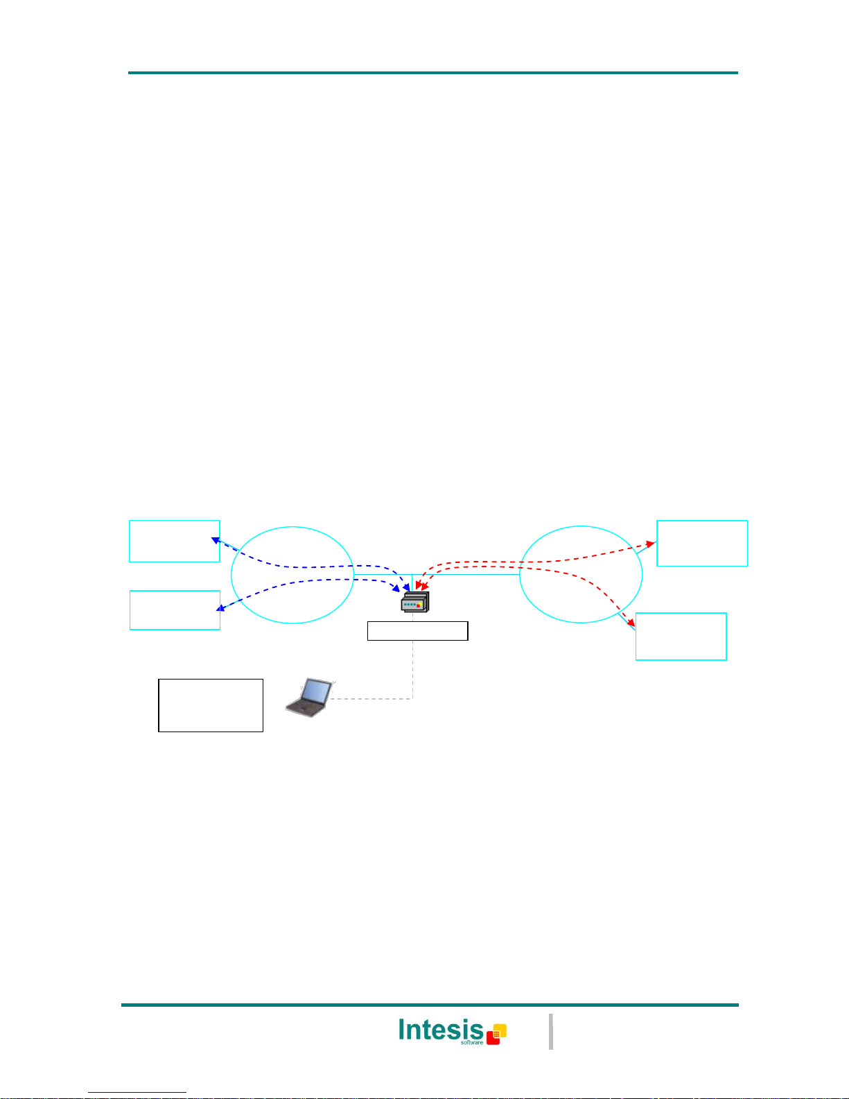
The aim of this integration is to make accessible Modbus TCP system signals and resources
from a BACnet/IP based control system or device, as if it was a part of the own BACnet
system and vice-versa. For this, the gateway acts as a BACnet/IP Server device in its
BACnet interface, allowing other BACnet/IP devices to perform subscription (COV) requests,
and also read and write its internal points. From the Modbus TCP system point of view,
IntesisBox simulates a Modbus master device, the readings of the Modbus TCP slave
device(s) is performed by IntesisBox by automatic continuous polling.
BACnet IP
client
Ethernet
IntesisBox
LinkBoxBacnet
configuration
software
Only needed for configuration
RS232
LAN
TCP/IP
BACnet IP
BACnet IP
client
Modbus
slave
Modbus
TCP
Modbus
slave
Figure 1.1 Integration of Modbus TCP and BACnet/IP using IntesisBox BACnet/IP
Server - Modbus TCP Master gateway
Page 6

IntesisBox® BACnet/IP Server - Modbus TCP Master
User’s Manual r1 eng
© Intesis Software S.L. - All rights reserved
This information is subject to change without notice
IntesisBox® is a registered trademark of Intesis Software SL
URL
Email
tel
http://www.intesis.com
info@intesis.com
+34 938047134
6 / 27
1.2 Functionality
The integration operation is as follow:
From the Modbus TCP system point of view, after the start up process, IntesisBox reads
continuously the points configured to be read in the Modbus TCP slave devices, and updates
in its memory all the values received from the Modbus TCP system.
From the BACnet system point of view, after the start up process, the gateway listen for any
subscription (COV) request, serves any polling request, or performs any writing request of
its internal points received from BACnet system. The values received from BACnet are
immediately written in the associated register of the corresponding Modbus TCP slave
device.
Every one of the Modbus TCP registers in the slave devices is associated to a BACnet object,
with this, all the Modbus TCP system (all the slave devices) is seen as a single BACnet
device with many objects from the BACnet system point of view, each object corresponding
to a Modbus TCP slave/register address.
When a new value is read from Modbus TCP for a given register, the new value is updated
in the gateway's memory and, if this signal is associated to a BACnet active subscription
then the new value will be sent to the subscripted BACnet device(s).
In the continuous polling of the Modbus TCP devices, if a non response of the Modbus TCP
device is detected, the corresponding virtual signal inside IntesisBox will be activated
indicating communication error with the Modbus TCP device. These virtual signals indicating
communication status in real time with the Modbus TCP devices are also accessible from
BACnet, like the rest of the points of IntesisBox.
Page 7

IntesisBox® BACnet/IP Server - Modbus TCP Master
User’s Manual r1 eng
© Intesis Software S.L. - All rights reserved
This information is subject to change without notice
IntesisBox® is a registered trademark of Intesis Software SL
URL
Email
tel
http://www.intesis.com
info@intesis.com
+34 938047134
7 / 27
1.3 Capacity of IntesisBox
Element
Tiny
version
Basic
version
Extended
version
Notes
Type of BACnet
devices
Only those supporting BACnet/IP.
Number of BACnet
points
110
500
3000
Maximum number of points that can be
defined in the virtual BACnet device
inside the gateway.
Number of BACnet
subscribers
8 8 8
Maximum number of BACnet
subscribers accepted by the gateway.
Number of BACnet
subscriptions
(COV) requests
220
1000
6000
Maximum number of BACnet
subscriptions (COV) requests accepted
by the gateway.
Type of Modbus
TCP slave devices
Those supporting Modbus TCP protocol.
Communication over TCP/IP.
Number of Modbus
TCP Slave devices
5 5 5
Number of Modbus TCP Slave devices
supported by the device
There are different models of IntesisBox BACnet/IP Server - Modbus TCP Master, with
different capacity every one of them.
Tiny model with capacity of 110 internal data points.
Ref.: IBOX-BAC-MBTCP-100.
Basic model with capacity of 500 internal data points.
Ref.: IBOX-BAC-MBTCP-A.
Extended model with capacity of 3000 internal data points.
Ref.: IBOX-BAC-MBTCP-B.
Page 8

IntesisBox® BACnet/IP Server - Modbus TCP Master
User’s Manual r1 eng
© Intesis Software S.L. - All rights reserved
This information is subject to change without notice
IntesisBox® is a registered trademark of Intesis Software SL
URL
Email
tel
http://www.intesis.com
info@intesis.com
+34 938047134
8 / 27
2. Interfaces
This section gives the reader an idea on how a Modbus TCP system/installation is integrated
with IntesisBox BACnet. It is not meant to provide an in-depth explanation on how BACnet
or Modbus TCP technology work as understanding the protocol principles is assumed
throughout this document.
The IntesisBox behaves as a regular BACnet device inside the BACnet system integrating all
the KNX devices. Note that each datapoint defined on IntesisBox will have two associated
data types:
One data-type, related to the BACnet/IP protocol of the IntesisBox
And another data-type, related to Modbus TCP side of IntesisBox
Conversions of data values from Modbus TCP to BACnet/IP data-types (and vice versa) are
internally performed at application level of IntesisBox, and keeping the highest possible
level of precision, with the restrictions of the data-type itself. Further detail on behavior and
data-types of the BACnet/IP and Modbus TCP interfaces of IntesisBox is given in the
following sections.
All configuration of IntesisBox BACnet is done using software tool LinkBoxBacnet. This tool,
covered in depth in section 5, is used to define the Modbus TCP and BACnet related
parameters on each of the datapoints defined in IntesisBox.
2.1 BACnet
The IntesisBox integrates all the Modbus TCP devices in a single BACnet device. The
communication with the other BACnet devices is done via the Ethernet port of the gateway
which implements the BACnet ASHRAE 135 – 2001 Annex J - BACnet protocol.
The supported BACnet Objects and Building Blocks can be found in the PICS document
available on the web:
http://www.intesis.com/pdf/IntesisBox_BACnet_IP_Server_Modbus_TCP_master_PICS.pdf
Configuration of all BACnet/IP parameters of IntesisBox and their links to Modbus TCP using
LinkBoxBacnet software tool is covered in section 5.1.
2.2 Modbus TCP
Modbus TCP communication is characterised basically by the embedding of the Modbus RTU
protocol into TCP/IP frames. This communication over TCP/IP allows faster communication
and a longer distance between master and slave devices in comparison with RTU
communication over serial line, and can use common TCP/IP infrastructure in buildings as
well as communication over WAN or internet. It allows also the co-existence of one or more
masters and of course one or more slave devices in a given network, all of them
interconnected through a TCP/IP based network.
IntesisBox acts as master in the Modbus TCP network, and the other Modbus devices
connected to the network communicating with IntesisBox must be always slave devices.
Up to 5 Modbus TCP slave devices can be defined in IntesisBox, to communicate with them.
Page 9

IntesisBox® BACnet/IP Server - Modbus TCP Master
User’s Manual r1 eng
© Intesis Software S.L. - All rights reserved
This information is subject to change without notice
IntesisBox® is a registered trademark of Intesis Software SL
URL
Email
tel
http://www.intesis.com
info@intesis.com
+34 938047134
9 / 27
For each point defined that belongs to a defined Modbus TCP slave device, a slave address
from 0 to 255 can be also freely configured, this feature allows great flexibility, for example
to integrate Modbus RTU slave devices connected in a serial line and with an RTU/TCP
converter on top of this serial line, enabling the access to the RTU slaves' points through
TCP/IP, in this case the RTU/TCP converter communicating in TCP identifies the destination
of the point (slave address in the RTU network) by the contents of the slave address field.
Modbus TCP slave devices are characterised by their IP address, and their predefined
registers address map, this address map specifies the address, type and characteristics of
each internal point (commonly called register) of the Modbus slave device, these registers
being accessible using Modbus TCP protocol.
Communication parameters of IntesisBox Modbus TCP interface (IP address, Net Mask,
Default router address, and TCP port) are fully configurable to adapt to any IP network and
slave device.
Modbus TCP protocol defines different types of function codes to use to read/write different
type of registers that can be found in Modbus devices, and also different data formats to
encode values.
Also the data encoding used for 16 bits registers (big-endian or little-endian) can be
configured in IntesisBox Modbus interface. This is the byte order for data encoding
(MSB..LSB or LSB..MSB). This data encoding, although is specified as big-endian in Modbus
protocol specification, it varies depending on manufacturer/type of slave.
All this gives great flexibility to integrate a wide range of Modbus slave devices that can be
found in the market.
Page 10

IntesisBox® BACnet/IP Server - Modbus TCP Master
User’s Manual r1 eng
© Intesis Software S.L. - All rights reserved
This information is subject to change without notice
IntesisBox® is a registered trademark of Intesis Software SL
URL
Email
tel
http://www.intesis.com
info@intesis.com
+34 938047134
10 / 27
3. Quick Setup
1. Install LinkBoxBacnet. Details in section 5
2. Install IntesisBox in the desired installation site (DIN rail mounting inside a metallic
industrial cabinet connected to ground is recommended).
3. Power up and connect the communication cables. Details in section 4.
4. Open LinkBoxBacnet, open a project or create a new one. Details in section 5.
5. Connect to the IntesisBox (details in section 5).
6. (optional) Configure the IntesisBox. Details in section 5.1.
7. Check if there is communication in both BACnet and Modbus TCP buses (section 5)
8. The IntesisBox is ready to be used in your system.
Page 11
IntesisBox® BACnet/IP Server - Modbus TCP Master
User’s Manual r1 eng
© Intesis Software S.L. - All rights reserved
This information is subject to change without notice
IntesisBox® is a registered trademark of Intesis Software SL
URL
Email
tel
http://www.intesis.com
info@intesis.com
+34 938047134
11 / 27
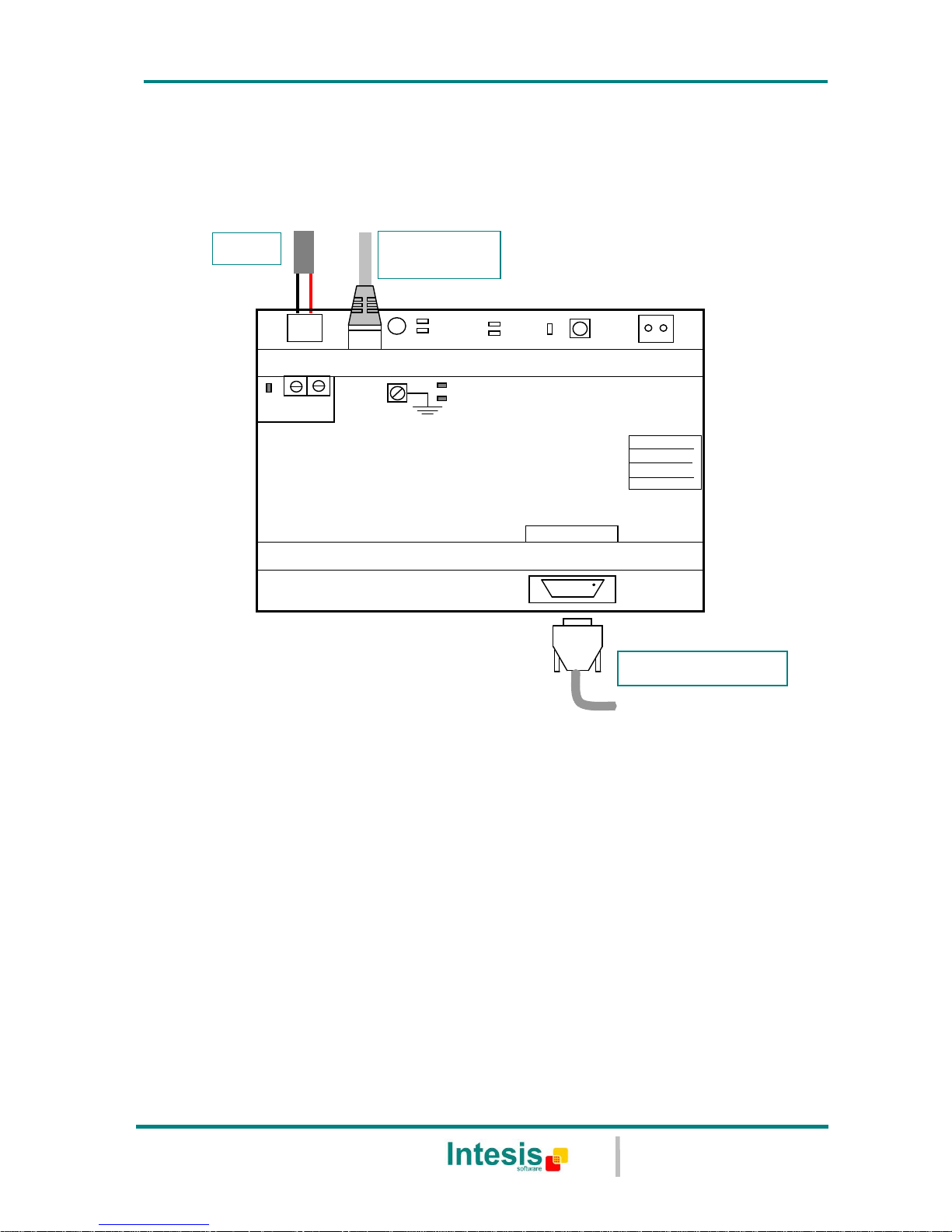
4. Connection
The device uses a standard enclosure allowing DIN EN60715 TH35 rail mounting. Its plastic
meets standard PC UL 94 V0.
Figure 4.1 Device connection diagram
Ensure proper space for all connectors when mounted.
The items supplied by Intesis Software for this integration are:
IntesisBox BACnet/IP Server - Modbus TCP Master hardware
Console cable. Standard DB9F-DB9M cable 1.8 meter long.
Installation sheet, containing a link to the LinkBoxBacnet software and this
manual.
4.1 Power device
The first step to perform is to power up the device. To do so a power supply working with
any of the voltage range allowed is needed (check section 6). Once connected the ON led
(Figure 4.1) will turn on.
WARNING! In order to avoid earth loops that can damage the gateway and/or any other
equipment connected to it, we strongly recommend:
ON
Power
9 – 30 Vdc
Max. 125mA
24 Vac
Max. 127mA
50-60Hz
CMN 24Vac
PC Console
Area .
Line .
Com .
IntesisBox
®
www.intesis.com
IBOX-BAC-MBTCP
BACnet/IP
Modbus TCP
ETH
10 Base-T
ACT
LNK
Power
PC (LinkBoxBacnet)
BACnet/IP
Modbus TCP
PC
Console
Page 12

IntesisBox® BACnet/IP Server - Modbus TCP Master
User’s Manual r1 eng
© Intesis Software S.L. - All rights reserved
This information is subject to change without notice
IntesisBox® is a registered trademark of Intesis Software SL
URL
Email
tel
http://www.intesis.com
info@intesis.com
+34 938047134
12 / 27
The use of DC power supplies, floating or with the negative terminal connected to
earth. Never use a DC power supply with the positive terminal connected
to earth.
The use of AC power supplies only if they are floating and not powering any other
device.
4.2 Connect to Modbus TCP
Connect the communication cable coming from the network hub or switch to the ETH port
(Figure 4.1) of IntesisBox. The cable to be used depends on where the IntesisBox is being
connected:
Connecting directly to a Modbus TCP device: crossover Ethernet UTP/FTP CAT5
cable
Connecting to a hub or switch of the LAN of the building: a straight Ethernet UTP/FTP
CAT5 cable
How to check if there is communication with the Modbus TCP bus is explained in the
LinkBoxBacnet Manual (section 5).
4.3 Connect to BACnet
Connect the communication cable coming from the network hub or switch to the ETH port
(Figure 4.1) of IntesisBox. The cable to be used depends on where the IntesisBox is being
connected:
Connecting directly to a BACnet/IP device: crossover Ethernet UTP/FTP CAT5 cable
Connecting to a hub or switch of the LAN of the building: a straight Ethernet UTP/FTP
CAT5 cable
In case there is no response from the BACnet devices to the frames sent by IntesisBox,
check that they are operative and reachable from the network connection used by
IntesisBox. Check the IntesisBox Ethernet interface sending Pings to its IP address using a
PC connected to the same Ethernet network.
4.4 Connect to PC (LinkBoxBacnet)
This action allows the user to have access to configuration and monitoring of the device
(more information can be found in the LinkBoxBacnet User Manual [section 5]). Two
methods to connect to the PC can be used:
Ethernet: Using the ETH port (Figure 4.1) of IntesisBox. How to check connectivity is
explained in section 4.3.
Serial cable: To connect the device to the PC the serial cable supplied should be
plugged to the PC console port (Figure 4.1).
The cable is a RS-232 straight cable and its pinout is at explained in Table 4.1.
Page 13

IntesisBox® BACnet/IP Server - Modbus TCP Master
User’s Manual r1 eng
© Intesis Software S.L. - All rights reserved
This information is subject to change without notice
IntesisBox® is a registered trademark of Intesis Software SL
URL
Email
tel
http://www.intesis.com
info@intesis.com
+34 938047134
13 / 27
IntesisBox
PC
DB9 M
RS-232 (Straight)
DB9 F
TX
2 2
RX
RX
3 3
TX
GND
5 5
GND
Table 4.1 Configuration serial cable pinout
Page 14

IntesisBox® BACnet/IP Server - Modbus TCP Master
User’s Manual r1 eng
© Intesis Software S.L. - All rights reserved
This information is subject to change without notice
IntesisBox® is a registered trademark of Intesis Software SL
URL
Email
tel
http://www.intesis.com
info@intesis.com
+34 938047134
14 / 27
5. LinkBoxBacnet. Configuration & monitoring of IntesisBox BACnet
series
How to install and use the LinkBoxBacnet is explained in its Manual. It can be found in the
installation folder (if the Software is already installed) or it can be downloaded from the link
that can be found in the installation sheet supplied with the IntesisBox.
In this section only the specific project configuration for IntesisBox BACnet/IP Server Modbus TCP Master is going to be explained.
The External Protocol in this IntesisBox is Modbus TCP
5.1 Project configuration
To configure the integration connection parameters, and the points list, click on Config in
the Button Bar (Figure 5.1). The Modbus TCP Configuration window will be opened. For
integrations with a large number of points an alternative CSV based configuration method is
explained in the LinkBoxBacnet Manual.
Figure 5.1 Menu and Button Bar in LinkBoxBacnet
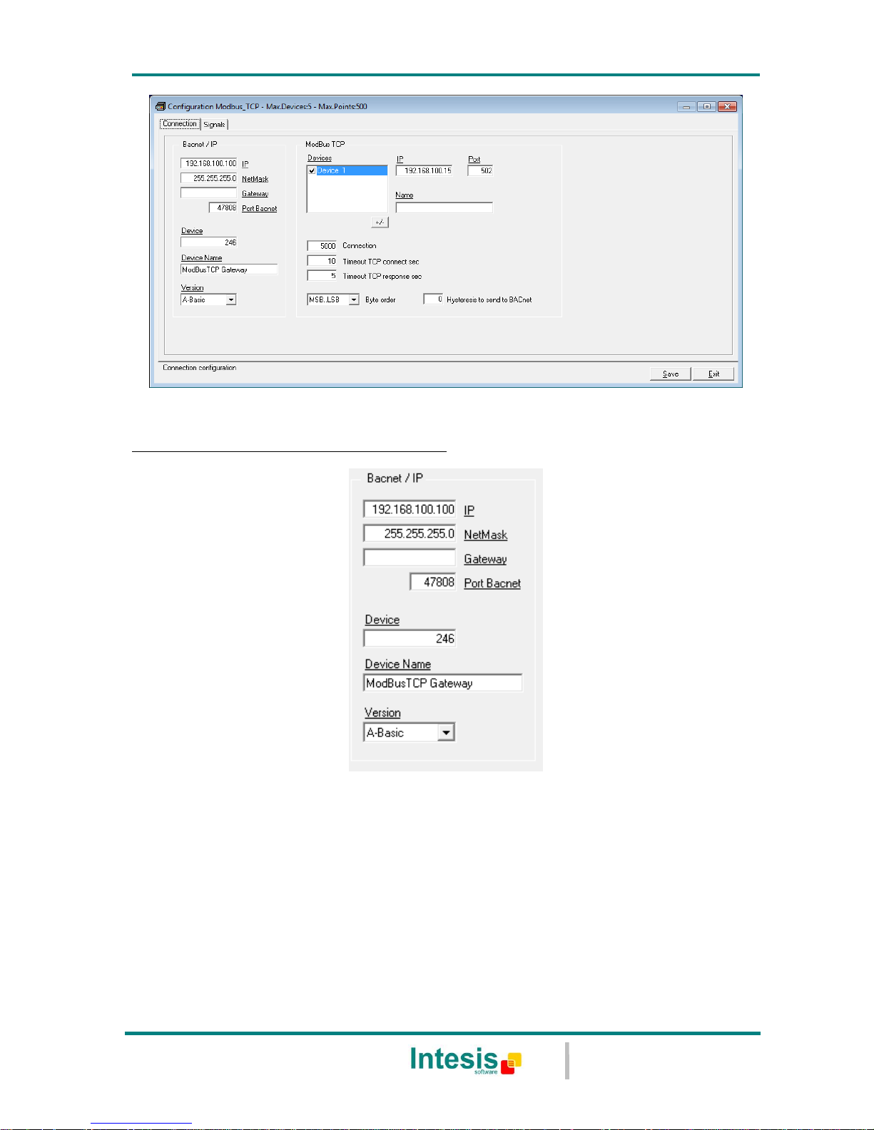
5.1.1 Connection configuration
Two subsets of information are configured using this window, the BACnet/IP parameters of
the IntesisBox, and the parameters of the Modbus TCP interface.
Page 15
IntesisBox® BACnet/IP Server - Modbus TCP Master
User’s Manual r1 eng
© Intesis Software S.L. - All rights reserved
This information is subject to change without notice
IntesisBox® is a registered trademark of Intesis Software SL
URL
Email
tel
http://www.intesis.com
info@intesis.com
+34 938047134
15 / 27
Figure 5.2 Configuration: Connection Tab
BACnet/IP interface configuration parameters:
Figure 5.3 BACnet/IP interface Configuration
IP: Enter the IP address for the gateway (supplied by the network administrator).
NetMask: Enter the IP NetMask for the gateway (supplied by the network
administrator).
Gateway: Enter the Default Gateway address (router address) in case the gateway
(IntesisBox) is in a different sub network than other BACnet devices (supplied by the
network administrator). Leave blank if there is no need of router address.
BACnet Port: Enter the BACnet port number used by the gateway (by default
47808, which is BAC0).
Page 16
IntesisBox® BACnet/IP Server - Modbus TCP Master
User’s Manual r1 eng
© Intesis Software S.L. - All rights reserved
This information is subject to change without notice
IntesisBox® is a registered trademark of Intesis Software SL
URL
Email
tel
http://www.intesis.com
info@intesis.com
+34 938047134
16 / 27
Device: Enter the BACnet device number for the gateway (must be unique inside the
BACnet system).
Device Name: Select the BACnet device name for the gateway (by default "Modbus
TCP Gateway"). This name will be collected by BACnet browsers among others.
Version: Select the gateway model used: tiny,basic or extended. You can check the
gateway model in the identification given by the device when it connects to
LinkBoxBacnet, it appears in the IntesisBox Communication Console window once
connected to the gateway
IntesisBox_Bacnet_Modbus TCP-100… Tiny model
IntesisBox_Bacnet_Modbus TCP-A… Basic model
IntesisBox_Bacnet_Modbus TCP-B… Extended model
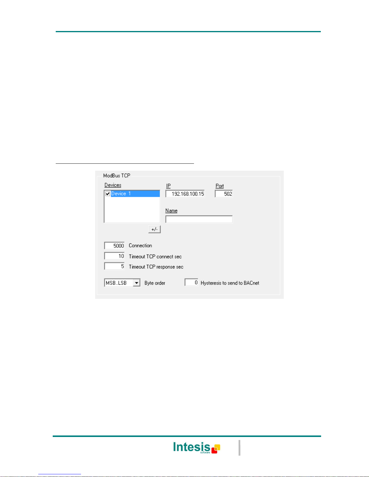
Modbus TCP interface configuration parameters:
Figure 5.4 Modbus TCP interface Configuration
Devices: List of Modbus TCP slave devices to communicate to. Check the devices
you want to activate. Select a device to configure its properties.
+/- : Use this button to define the number of Modbus TCP slave devices to
communicate to (Up to 254 devices)
For every Modbus TCP device defined, the following properties must be entered:
IP: IP of each slave device
Port: Port of each slave device
Name: Enter the device name (optional, just for identification purposes).
Timeout between Connections (ms): time to wait before retrying the connection
again if it failed
Page 17

IntesisBox® BACnet/IP Server - Modbus TCP Master
User’s Manual r1 eng
© Intesis Software S.L. - All rights reserved
This information is subject to change without notice
IntesisBox® is a registered trademark of Intesis Software SL
URL
Email
tel
http://www.intesis.com
info@intesis.com
+34 938047134
17 / 27
Timeout TCP connect (sec): timeout to decide that a connection was not
successful.
Timeout TCP response (sec): timeout to decide that a the device has not replied.
Byte order (Modbus TCP endianism): Byte order for data fields inside Modbus TCP
telegrams (LSB..MSB or MSB..LSB). It will depend on the slaves, consult the slave
documentation for details. If unknown just try the two possible choices and see if the
read values make sense. This affects to all data fields of all slaves defined.
Hysteresis to send to BACnet: Amount that a Modbus TCP value needs to change
to be sent to the BACnet COV subscriptions
5.1.2 Signals configuration
Select the Signals tab (Figure 5.5) to configure the signals list (the IntesisBox internal
points). More information about the meaning of the columns can be found in the tables
below.
Every row in the grid corresponds to a signal (point). Signals (rows in the grid) can be
added or deleted selecting the desired row and clicking Add or Delete buttons. Multiple
consecutive rows can be deleted too.
Figure 5.5 Signal list
# (Signal’s number)
Description
Enumeration of the rows in the grid (signals). If clicked on them the whole
row will be selected ( to be used to delete/add rows)
Restrictions
Cannot be edited
Page 18

IntesisBox® BACnet/IP Server - Modbus TCP Master
User’s Manual r1 eng
© Intesis Software S.L. - All rights reserved
This information is subject to change without notice
IntesisBox® is a registered trademark of Intesis Software SL
URL
Email
tel
http://www.intesis.com
info@intesis.com
+34 938047134
18 / 27
Dev
Description
Device number to which belongs the point. Referenced to the list of devices
defined in Connection Tab (Figure 5.4)
Values
From 1 to 5
Edit mode
Text edit or AutoEnumeration
Comments
This is not the slave number configured in the Modbus TCP device itself, it is
just the order of the device (from top to bottom) in the devices list
Slave
Description
Modbus Slave number
Values
From 1 to 255
Edit mode
Text edit or AutoEnumeration
Modbus Code
Description
Modbus function code to be used by IntesisBox to read, to write or to
read/write the point in the slave device.
Values
0- Communication Error
1- Read digital outputs
2- Read digital inputs
3- Read analog registers
4- Read analog inputs
5- Write 1 digital output
6- Write 1 analog register
7- Write multiple digital output
8- Write multiple analog registers
Restrictions
For Read only points function codes 1, 2, 3 or 4 can be used
For write only points, function codes 5, 6, 15 or 16 can be used
For read/write points, see section 5.1.3
Edit mode
Single / Multiple Values selection.
Comments
Consult documentation of Modbus device(s) to integrate for information about function codes
supported to read/write their internal points.
Page 19

IntesisBox® BACnet/IP Server - Modbus TCP Master
User’s Manual r1 eng
© Intesis Software S.L. - All rights reserved
This information is subject to change without notice
IntesisBox® is a registered trademark of Intesis Software SL
URL
Email
tel
http://www.intesis.com
info@intesis.com
+34 938047134
19 / 27
Format
Description
Modbus TCP data format for the point.
Values
1. 1 bit.
2. 16 bits uns: 16 bits unsigned.
3. 16 bits sig: 16 bits signed. The MSbit represents the sign.
4. 16 bits sig C2:16 bits signed (two’s complement).
5. 32 bits uns: 32 bits unsigned.
6. 32 bits sig: 32 bits signed.
7. 32 bits sig C2: 32 bits signed (two’s complement).
8. 32 bits IEEE: IEEE Standard for Floating-Point Arithmetic (IEEE 754).
9. 32 bits IEEE inv: 32 bits IEEE inverted (LSB..MSB).
10. 32 bits IEEE Winv: 32 bits IEEE word inverted (LSW..MSW).
Device Specific:
11. 16 bits digital: Bit coded into 16 bits register.
12. 32 bits Mod10K uns: Integer N as 2 16-bit integers A and B. where
N= (A * 10.000) + B
13. 48 bits Mod10K uns: Integer N as 3 16-bit integers A, B and C where
N= (A * 10.0002) +(B * 10.000) + C
14. 64 bits Mod10K uns: Integer N as 4 16-bit integers A, B, C and D
where N= (A * 10.0003) + (B * 10.0002) +(C * 10.000) + D
15. 32 bits Mod10K sig: as the unsigned but the MSb represents the sign.
16. 48 bits Mod10K sig: as the unsigned but the MSb represents the sign.
17. 64 bits Mod10K sig: as the unsigned but the MSb represents the sign.
18. 32 bits Mod10K ION: to be used with ION devices.
19. 32 bits ION sig: to be used with ION devices.
20. 32 bits Invertomatic: to be used with Invertomatic devices.
21. MSB*100 + LSB.
Restrictions
1 bit format can only be used with digital Modbus TCP codes (1,2,5 and 6)
All the other formats cannot be used with the abovementioned codes
Edit mode
Single / Multiple Values selection.
Comments
Formats 1 to 9 are generic Modbus TCP data formats while formats 10 to 20
are Device specific.
Page 20

IntesisBox® BACnet/IP Server - Modbus TCP Master
User’s Manual r1 eng
© Intesis Software S.L. - All rights reserved
This information is subject to change without notice
IntesisBox® is a registered trademark of Intesis Software SL
URL
Email
tel
http://www.intesis.com
info@intesis.com
+34 938047134
20 / 27
Consult documentation of Modbus device(s) to integrate for information about Modbus data
format of the points desired to integrate.
Address
Description
It's the Modbus TCP register address to use by IntesisBox to read/write the
point into the Modbus TCP device.
Edit mode
Text edit or AutoEnumeration
Comments
Consult documentation of Modbus device(s) to integrate for information about register
addresses of the points desired to integrate.
Bit
Description
Bit used inside the Modbus TCP register to encode the digital value for the
point. IntesisBox allows bit decoding from generic 16 bits input/holding
Modbus TCP registers. Bit coding into 16 bit input/holding Modbus TCP
registers is used for some devices to encode digital values into this type of
registers.
Values
0 to 15
Restrictions
Only used with Format=11 (16 bits digital) and Code= 3 or 4 (read
holding/input registers).
To decode more than one of the bits of the 16 bits register all the decoding
rows should be grouped together in the table
Edit mode
Text edit
Frac
Description
Fractional part to consider for the point's value when read/write. Some
devices encode for example temperature values (integer + fractional part) in
common 2-bytes Modbus TCP registers (using data format 16 bits signed
two's complement for example); the problem of using 2-bytes registers is
that no fractional part can be encoded.
To avoid this problem, the real value in the device is sent multiplied by 10 as
just integer part (a real value of 25.1 will be sent as 251). For this kind of
points for example you can specify a value of 1 in Frac column. Then the
value decoded by IntesisBox from the slave will be divided by 10, and the
value will be multiplied by 10 before writing to the slave, thus will be the
real value in the device (including integer and fractional part).
Edit mode
Text edit or AutoEnumeration
Page 21

IntesisBox® BACnet/IP Server - Modbus TCP Master
User’s Manual r1 eng
© Intesis Software S.L. - All rights reserved
This information is subject to change without notice
IntesisBox® is a registered trademark of Intesis Software SL
URL
Email
tel
http://www.intesis.com
info@intesis.com
+34 938047134
21 / 27
Bac.Name
Description
BACnet object name for the signal. This name is included into the BACnet's
Object_name property for the point and it will be collected by any BACnet
explorer.
Restrictions
Maximum 30 characters
Edit mode
Text edit
Comments
Recommended to give a descriptive name to each point with indication of
the Modbus TCP slave/register associated
Bac.Type
Description
BACnet object type for the signal.
Values
AI = Analog Input.
AO = Analog Output.
AV = Analog Value.
DI = Digital Input.
DO = Digital Output.
DV = Digital Value.
MI = Multistate Input.
MO = Multistate Output.
MV = Multistate Value.
Edit mode
Single / Multiple Values selection.
Comments
Edit using the mouse right-button-click pop-up menu
Bac.ID
Description
BACnet object instance number for the point. It can be manually entered by
the user or can be automatically assigned by LinkBoxBacnet when saving the
configuration (section 5.1.4)
Restrictions
All the object instance numbers for objects of the same type must be
different
Edit mode
Text edit or AutoEnumeration
Comments
It is recommended to let LinkBoxBacnet assign automatically object instance
numbers for the points
Page 22

IntesisBox® BACnet/IP Server - Modbus TCP Master
User’s Manual r1 eng
© Intesis Software S.L. - All rights reserved
This information is subject to change without notice
IntesisBox® is a registered trademark of Intesis Software SL
URL
Email
tel
http://www.intesis.com
info@intesis.com
+34 938047134
22 / 27
Active
Description
Indicates if the signal is active or not for the integration
Values
0: Not active
1: Active
Edit mode
Text edit or AutoEnumeration
0 / 1 based register
Description
Some Modbus TCP devices use 0-based register addresses (also referred as
Jbus), while others use 1-based register addresses (also referred as Modbus
TCP), in the Modbus TCP communication (for 1-based devices, the register
address 100 is specified as 99 in the Modbus TCP communication frames).
Select 0-Based if your Modbus TCP devices use 0-based address map (like
PLCs), or select 1-Based if your Modbus TCP devices use 1-based address
map.
Description
Buttons to move the selected row (or rows) up or down inside the grid. To
move up or down inside the grid a single row or a group of consecutive
rows, just select the row or rows using the left button of the mouse and
push the desired up or down button.
Comments
This can be done also using the key combinations ALT+arrow up or
ALT+arrow down instead of up or down buttons
Add
Description
Button that adds a row under the selected one.
Delete
Description
Buttons to delete the selected row (or rows).
Save
Description
Save the configuration (details in section 5.1.4)
Exit
Description
Exits the configuration window (details in section 5.1.4)
Page 23

IntesisBox® BACnet/IP Server - Modbus TCP Master
User’s Manual r1 eng
© Intesis Software S.L. - All rights reserved
This information is subject to change without notice
IntesisBox® is a registered trademark of Intesis Software SL
URL
Email
tel
http://www.intesis.com
info@intesis.com
+34 938047134
23 / 27
5.1.3 How to configure read/write points
First of all is important to take into account that different names for Modbus TCP function
codes, are used in technical literature depending on the manufacturer of the Modbus TCP
device. The following table shows the equivalence between nomenclature for function codes,
used by Intesis Software in IntesisBox and the used in Modbus TCP protocol specification.
Function code IntesisBox Modbus TCP protocol specification
01 Read digital outputs Read Coils
02 Read digital inputs Read Discrete Inputs
03 Read analog registers Read Holding Registers
04 Read analog inputs Read Input Registers
05 Write 1 digital output Write Single Coil
06 Write 1 analog register Write Single Register
15 Write multiple digital outputs Write Multiple Coils
16 Write multiple analog registers Write Multiple Registers
Given a point in a Modbus TCP slave device, if this point allows to be read and written,
different Modbus TCP function codes must be used for read and for write actions (consult
the slave documentation for details of what function codes must be used for read and for
write). Use the following criteria for configuration of this kind of points in IntesisBox:
1. If the Modbus TCP function code to use for read is 03 and the function code to use for
write is 06 (which is very common), then select the function code 3-Read analog
registers in column Modbus TCP Code and select a BACnet Type Output or Value for the
point (i.e. AO, AV, BO, BV, MO, MV). With this, IntesisBox will use function code 03 for
read the point in every polling cycle, and whenever a new value for the point is received
from BACnet, the new value will be written in the Modbus TCP slave device using
function code 06.
2. If the Modbus TCP function code to use for read is 01 and the function code to use for
write is 05 (which is also very common), then select the function code 1-Read digital
outputs in column Modbus TCP Code and select a BACnet Type Output or Value for the
point (i.e. AO, AV, BO, BV, MO, MV). With this, IntesisBox will use function code 01 for
read the point in every polling cycle, and whenever a new value for the point is received
from BACnet, the new value will be written in the Modbus TCP slave device using
function code 05.
3. If the Modbus TCP function code to use for read and the function code to use for write
are different than 01-05 or 03-06 (sometimes found with specific devices), then you
have to declare two points in IntesisBox to perform the read and the write separately.
The way to configure this is better explained using an example.
Imagine you have a device, in which a given analog point (register address 100 for
example) of type read/write must be read using function code 03, and must be write
using function code 16.
To be able to read and write this Modbus TCP point from BACnet, you must define two
separate points into IntesisBox, one for read and one for write like the following:
Nb
Dev
Modbus Code
Format
Add.
Bit
Frac
Bac.Name
Bac.Type
Bac.ID
Active
1 1 3-Read analog registers
4 - 16 bits sig C2
100 0
AI - example of Read Modbus point
0 -AI
0
1-Yes 2 1
16-Write multiple analog registers
4 - 16 bits sig C2
100 0
AO - example of Write Modbus point
1-AO
0
1-Yes
The important configuration parameters to obtain the desired functionality are highlighted in green
colour, the rest of configuration parameters are irrelevant in this example. Note that both points must
have the same Modbus TCP Address and the same Modbus TCP Format.
Page 24

IntesisBox® BACnet/IP Server - Modbus TCP Master
User’s Manual r1 eng
© Intesis Software S.L. - All rights reserved
This information is subject to change without notice
IntesisBox® is a registered trademark of Intesis Software SL
URL
Email
tel
http://www.intesis.com
info@intesis.com
+34 938047134
24 / 27
5.1.4 Saving the configuration
When the configuration of the project is finished follow the next steps:
1. Click the button Save. Once accepted the pop-up message, that will save the project
in the folder on hard disk (more information in LinkBoxBacnet Manual).
2. You will be prompted to generate the configuration file to be sent to the gateway,
a. If YES is selected, the binary file (Modbus TCP.LBOX) containing the
configuration for the gateway will be generated and saved also into the
project folder.
b. If NO is selected the binary file needs to be created before following the next
steps. To do so open the Configuration window (section 5.1) and restart from
step 1
3. A pop-up message will show up asking if you want to preserve the Object
instance numbers. BE CAREFUL using this feature.
a. If NO is selected all the object instance numbers for the points will be
automatically reconstructed and thus loosing previous instance numbers, if
defined. ONLY USE this option for a brand new configuration not
previously running in the gateway and therefore not yet integrated into the
BACnet system
b. Select Yes for configurations previously running in the gateway and
already integrated into the BACnet system that had been extended with
a few more points that must respect the previously defined object
instance numbers. All the points with object instance numbers defined will
be respected. LinkBoxBacnet will automatically assign object instance
numbers to ones without it.
4. As the final step, a pop-up message will ask if you want to see the BACnet points list
report, If you select Yes, a text file called Modbus TCP- BACNET OBJECT LIST.TXT
will be generated and saved into the project folder containing a report of all the
point's BACnet information (for informative purposes at user level). The file will be
also opened in the notepad, it looks like this:
ObjIdent ObjType OInst ObjName
00000000 0-AI 0000 AI_1_read
00000001 0-AI 0001 AI_2_read
04194304 1-AO 0000 AO_1_read_write
04194305 1-AO 0001 AO_2_read
04194306 1-AO 0002 AO_3_write
08388608 2-AV 0000 AV_1_read_write
08388609 2-AV 0001 AV_2_read
12582912 3-BI 0000 Communication Error Dev.1
12582913 3-BI 0001 BI_1_read
12582914 3-BI 0002 BI_2_read
12582915 3-BI 0003 BI_10
12582916 3-BI 0004 BI_11
16777216 4-BO 0000 B0_1_read_write
16777217 4-BO 0001 BO_2_read_write
20971520 5-BV 0000 BV_1_read_write
Page 25

IntesisBox® BACnet/IP Server - Modbus TCP Master
User’s Manual r1 eng
© Intesis Software S.L. - All rights reserved
This information is subject to change without notice
IntesisBox® is a registered trademark of Intesis Software SL
URL
Email
tel
http://www.intesis.com
info@intesis.com
+34 938047134
25 / 27
5. Once in the configuration window again, click on exit. The configuration is ready to
be sent to the IntesisBox (check LinkBoxBacnet Manual)
The configuration cannot be received from the gateway to LinkBoxBacnet, it can
only be sent.
Page 26

IntesisBox® BACnet/IP Server - Modbus TCP Master
User’s Manual r1 eng
© Intesis Software S.L. - All rights reserved
This information is subject to change without notice
IntesisBox® is a registered trademark of Intesis Software SL
URL
Email
tel
http://www.intesis.com
info@intesis.com
+34 938047134
26 / 27
6. Mechanical & electrical characteristics
Enclosure
Plastic, type PC (UL 94 V-0).
Dimensions: 107mm x 105mm x 58mm.
Colour
Light Grey. RAL 7035.
Power
9 to 30Vdc +/-10%, Max.: 125mA.
24Vac +/-10% 50-60Hz, Max.: 127mA
Must use a NEC Class 2 or Limited Power Source (LPS) and SELV
rated power supply.
Plug-in terminal block for power connection (2 poles).
Terminal wiring (for
power supply and
low-voltage signals)
Per terminal: solid wires or stranded wires (twisted or with ferrule)
1 core: 0.5mm2… 2.5mm2
2 cores: 0.5mm2… 1.5mm2
3 cores: not permitted
Mounting
Wall.
DIN rail EN60715 TH35.
Modbus TCP &
BACnet/IP port
1 x Ethernet 10Base-T (RJ45).
LED indicators
1 x Power.
2 x Ethernet port link and activity (LNK, ACT).
Console port
EIA232. (DB9 female connector, DCE). SELV
Configuration
Via console port.1
Firmware
Allows upgrades via console port.
Operational
temperature
0°C to +70°C
Operational humidity
5 to 95%, non condensing
Protection
IP20 (IEC60529).
RoHS conformity
Compliant with RoHS directive (2002/95/CE).
Norms and
standards
CE conformity to EMC directive (2004/108/EC) and Low-voltage
directive (2006/95/EC)
EN 61000-6-2
EN 61000-6-3
EN 60950-1
EN 50491-3
1
Standard cable DB9male-DB9female 1,8 meters long is supplied with the device for connection to a PC COM port for
configuring and monitoring the device. The configuration software, compatible with Windows® operating systems, is also
supplied.
Page 27

IntesisBox® BACnet/IP Server - Modbus TCP Master
User’s Manual r1 eng
© Intesis Software S.L. - All rights reserved
This information is subject to change without notice
IntesisBox® is a registered trademark of Intesis Software SL
URL
Email
tel
http://www.intesis.com
info@intesis.com
+34 938047134
27 / 27
7. Dimensions
Free space recommended to install the device into a cabinet (wall or DIN rail mounting),
with space enough for external connections:
115 mm
130 mm
100 mm
58 mm
Power
+
Ethernet port
107 mm
105 mm
Console
port
 Loading...