

Page 1

IntesisBox
®
KNX
Hitachi VRF Air Conditioning
User Manual
Issu Date: 01/2019
r1.1 EN
Page 2

IntesisBox® KNX – HITACHI VRF User Manual r1.1 EN
2/30
This information is subject to change without prior notice
IntesisBox is a registered trademark of Intesis Software S.L.U.
email: info@intesisbox.com
web: www.intesisbox.com
phone: +34 938047134
© Intesis Software S.L.U. 2019 All Rights Reserved.
Information in this document is subject to change without notice. The software described in this document is furnished
under a license agreement or nondisclosure agreement. The software may be used only in accordance with the terms
of those agreements. No part of this publication may be reproduced, stored in a retrieval system or transmitted in any
form or any means electronic or mechanical, including photocopying and recording for any purpose other than the
purchaser’s personal use without the written permission of Intesis Software S.L.U.
Intesis Software S.L.U.
Milà i Fontanals, 1 bis
08700 Igualada
Spain
TRADEMARKS
All trademarks and tradenames used in this document are acknowledged to be the copyright of their respective holders.
Page 3

IntesisBox® KNX – HITACHI VRF User Manual r1.1 EN
3/30
This information is subject to change without prior notice
IntesisBox is a registered trademark of Intesis Software S.L.U.
email: info@intesisbox.com
web: www.intesisbox.com
phone: +34 938047134
Gateway for the integration of Hitachi VRF systems into KNX home
automation systems.
Order code:
IBKNXHIS016O000, 16 indoor units
IBKNXHIS064O000, 64 indoor units
Page 4

IntesisBox® KNX – HITACHI VRF User Manual r1.1 EN
4/30
This information is subject to change without prior notice
IntesisBox is a registered trademark of Intesis Software S.L.U.
email: info@intesisbox.com
web: www.intesisbox.com
phone: +34 938047134
INDEX
1 Description ............................................................................................................................................................ 5
Introduction .................................................................................................................................................... 5
1.1 Functionality...................................................................................................................................................... 6
Capacity of IntesisBox ................................................................................................................................... 7
2 KNX System .......................................................................................................................................................... 8
Description..................................................................................................................................................... 8
Points definition ............................................................................................................................................. 8
3 Connections .......................................................................................................................................................... 9
Power device ............................................................................................................................................... 10
Connect to Hitachi installation ..................................................................................................................... 10
Connection to KNX ...................................................................................................................................... 10
Connection to the configuration tool ............................................................................................................ 10
4 Set-up process and troubleshooting ................................................................................................................... 11
Pre-requisites .............................................................................................................................................. 11
IntesisBox MAPS. Configuration & monitoring tool for IntesisBox KNX series ........................................... 11
4.2.1 Introduction .......................................................................................................................................... 11
4.2.2 Connection ........................................................................................................................................... 11
4.2.3 Configuration tab ................................................................................................................................. 12
4.2.4 KNX configuration ................................................................................................................................ 12
4.2.5 Hitachi configuration ............................................................................................................................ 15
4.2.6 Signals ................................................................................................................................................. 17
4.2.7 Sending the configuration to IntesisBox .............................................................................................. 18
4.2.8 Diagnostic ............................................................................................................................................ 18
4.2.9 Set-up procedure ................................................................................................................................. 20
5 Electrical & Mechanical Features ........................................................................................................................ 21
6 Dimensions ......................................................................................................................................................... 22
7 AC Unit Types compatibility ................................................................................................................................ 23
8 Error codes for Indoor and Outdoor Units ........................................................................................................... 24
9 Appendix A – Communication Objects Table ..................................................................................................... 27
Page 5
IntesisBox® KNX – HITACHI VRF User Manual r1.1 EN
5/30
This information is subject to change without prior notice
IntesisBox is a registered trademark of Intesis Software S.L.U.
email: info@intesisbox.com
web: www.intesisbox.com
phone: +34 938047134
1 Description
Introduction
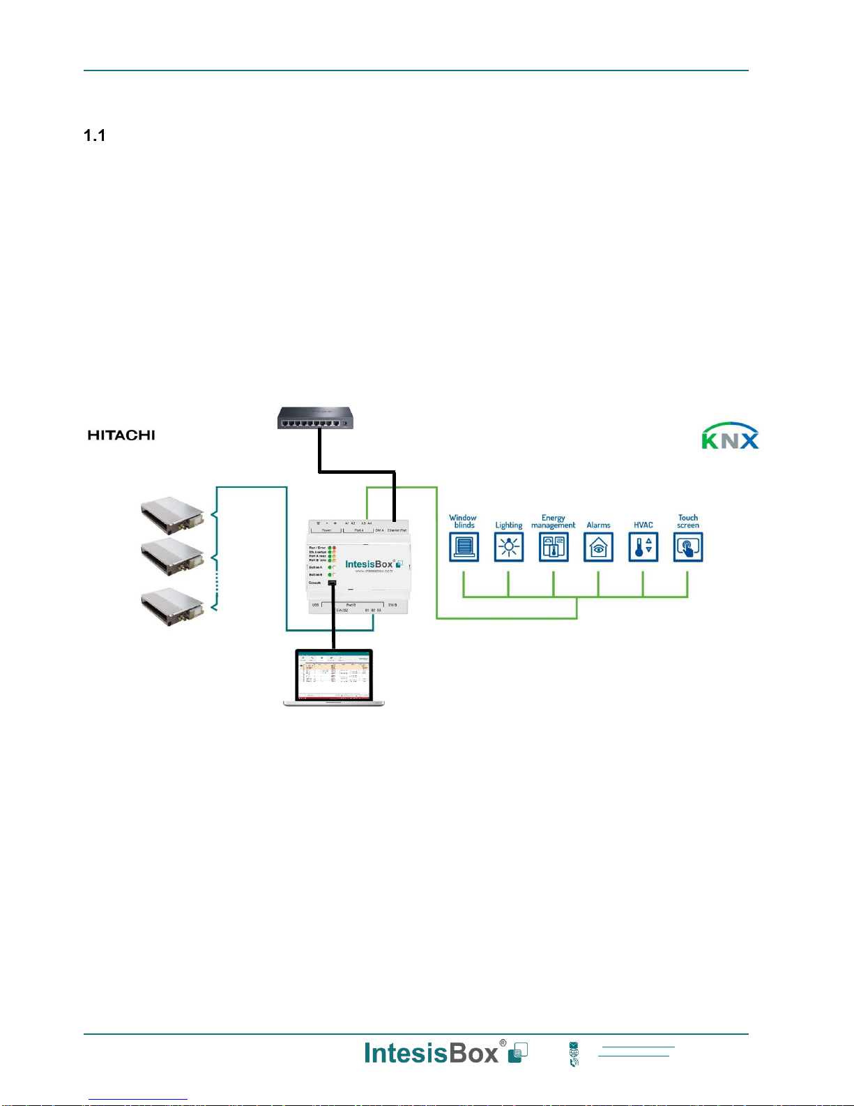
This document describes the integration of Hitachi VRF air conditioning systems into KNX home automation systems
using gateway IntesisBox KNX – Hitachi VRF.
The aim of this integration is to monitor and control your Hitachi air conditioning system, from your KNX TP-1 installation.
To do it so, IntesisBox performs as a one more KNX device, sending and receiving telegrams to group addresses in the
KNX network.
IntesisBox makes available the Hitachi air conditioning system indoor units’ datapoints through independent KNX
objects.
Up to 64 indoor units supported, depending on product version.
This document assumes that the user is familiar with KNX and Hitachi technologies and their technical terms.
Integration of Hitachi VRF systems into
KNX control systems
USB
configuration
Ethernet TCP
Ethernet
configuration
Page 6
IntesisBox® KNX – HITACHI VRF User Manual r1.1 EN
6/30
This information is subject to change without prior notice
IntesisBox is a registered trademark of Intesis Software S.L.U.
email: info@intesisbox.com
web: www.intesisbox.com
phone: +34 938047134
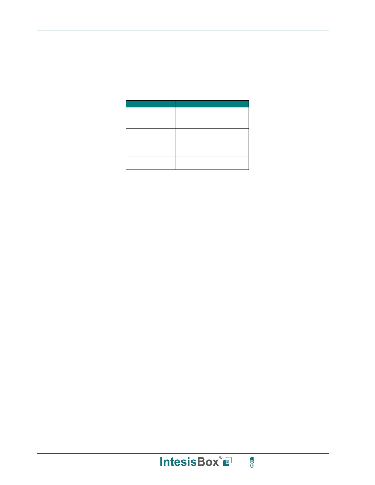
1.1 Functionality
IntesisBox® continuously monitors Hitachi VRF network for all configured signals and keeps the updated status of all of
them in its memory. It triggers updates on configured group addresses to KNX network on value change.
Commands toward the indoor unit communication adaptor are permitted.
Each indoor unit is offered as a set of KNX objects.
Element
Object supported
Outdoor Unit
• Communication
status
• Status
Indoor Unit
• Status
• Command
• Communication
status
General signals
(all units)
• Command
Page 7
IntesisBox® KNX – HITACHI VRF User Manual r1.1 EN
7/30
This information is subject to change without prior notice
IntesisBox is a registered trademark of Intesis Software S.L.U.
email: info@intesisbox.com
web: www.intesisbox.com
phone: +34 938047134
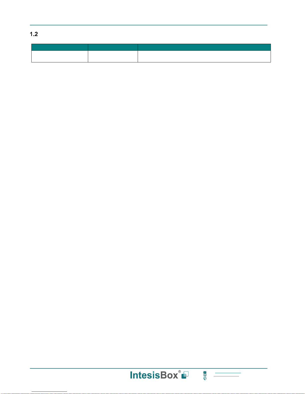
Capacity of IntesisBox
Element
Max.
Notes
Number of indoor units
64*
Number of indoor units that can be controlled through
IntesisBox
* There are different models of IntesisBox KNX – Hitachi VRF each one with different capacity. The table above shows
the capacity for the top model (with maximum capacity).
Their order codes are:
▪ IBKNXHIS016O000: Model supporting up to 16 indoor units
▪ IBKNXHIS064O000: Model supporting up to 64 indoor units
Page 8
IntesisBox® KNX – HITACHI VRF User Manual r1.1 EN
8/30
This information is subject to change without prior notice
IntesisBox is a registered trademark of Intesis Software S.L.U.
email: info@intesisbox.com
web: www.intesisbox.com
phone: +34 938047134
2 KNX System
In this section, a common description for all IntesisBox KNX series gateways is given, from the point of view of KNX
system which is called from now on internal system. Connection with the Hitachi system is also called from now on
external system.
Description
IntesisBox KNX connects directly to the KNX TP-1 bus and performs as one more device into the KNX system, with the
same configuration and operational characteristics as other KNX devices.
Internally, the circuit part connected to the KNX bus is opto-isolated from the rest of the electronics.
IntesisBox KNX receives, manages and sends all the telegrams related to its configuration to the KNX bus.
On receiving WRITE telegrams of KNX group addresses associated to communication objects, the corresponding
messages are sent to the external system (Hitachi installation).
When a change in a signal of the external system is detected, a WRITE telegram is sent to the KNX bus (addressed
with the group address associated to the corresponding group object), in order to maintain both systems synchronized
in every moment.
The status of the KNX bus is checked continuously and, if a bus drop-down is detected, for example due to failure in
the bus power supply, after the KNX bus is restored again, IntesisBox will send READ telegrams to group addresses of
all communication objects marked with flag ‘Ri’. The behavior of each individual point into IntesisBox is determined by
the flags configured for the communication object. See details below.
Points definition
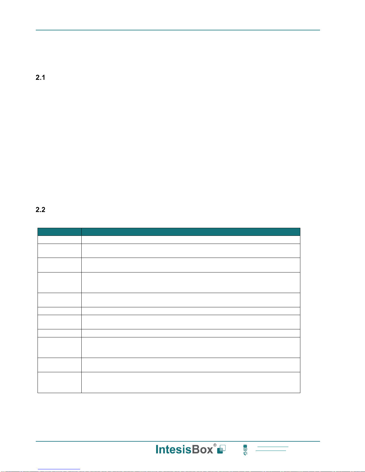
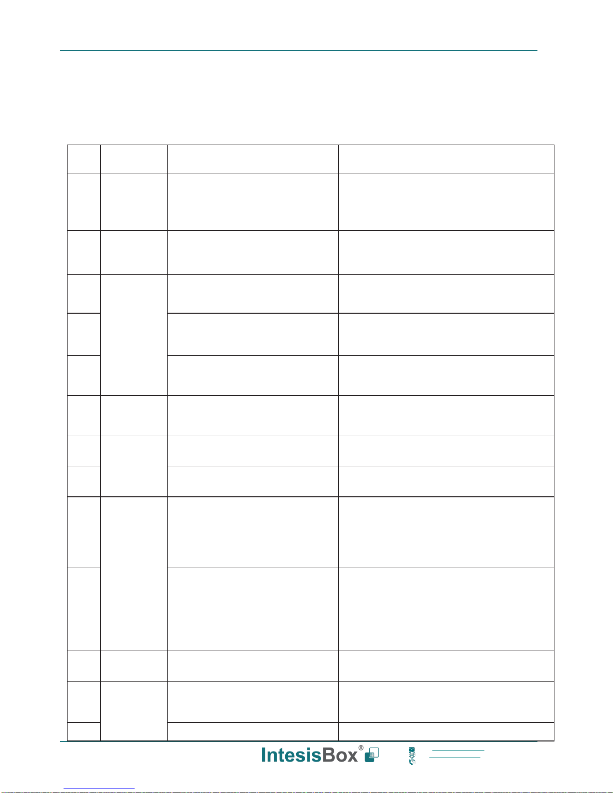
Every group object in configuration has following KNX properties:
Property
Description
Description
Descriptive information about the communication object or signal.
Object
function
Information on range of values for the group object.
DPT
Datapoint type. It is the KNX data type used to encode the signal's value. It will depend
on the type of signal associated in the external system in every case.
Group
It is the KNX group to which the point is associated. It is also the group to which the
read (R), write (W), transmit (T), update (U) and read on init (Ri) flags are applied. It is
the sending group.
Listening
addresses
They are the addresses that can write on the group object, a part of the main group
address.
R
Read. If this flag is activated, READ telegrams of this group address will be accepted.
Ri
Read on Init. If this flag is activated, the object will trigger corresponding READ request
(on associated group address) on initialization.
W
Write. If this flag is activated, WRITE telegrams on this group object will be accepted.
T
Transmit. If this flag is activated, when the group object value changes, due to a change
in the external system, a WRITE telegram of the associated group address will be sent
to the KNX bus.
U
Update. If this flag is activated, UPDATE telegrams (response to READ telegrams) on
this group object will be accepted.
Active
If activated, the point will be active in IntesisBox, if not, the behavior will be as if the
point is not defined. This allows deactivating points without the need of delete them for
possible future use.
These properties are common for all IntesisBox KNX series gateways. Although each integration may have specific
properties according to the type of signals of the external system.
See list of communication objects in section 9 APPENDIX A – COMMUNICATION OBJECTS TABLE.
Page 9

IntesisBox® KNX – HITACHI VRF User Manual r1.1 EN
9/30
This information is subject to change without prior notice
IntesisBox is a registered trademark of Intesis Software S.L.U.
email: info@intesisbox.com
web: www.intesisbox.com
phone: +34 938047134
3 Connections
Find below information regarding the IntesisBox connections available.
Power Supply
Must use NEC Class 2 or Limited Power Source (LPS) and SELV rated
power supply.
If using DC power supply:
Respect polarity applied of terminals (+) and (-). Be sure the voltage
applied is within the range admitted (check table below). The power
supply can be connected to earth but only through the negative
terminal, never through the positive terminal.
If using AC power supply:
Make sure the voltage applied is of the value admitted (24 Vac). Do
not connect any of the terminals of the AC power supply to earth, and
make sure the same power supply is not supplying any other device.
Ethernet
Connect the cable coming from the IP network to the connector ETH of
the gateway. Use an Ethernet CAT5 cable. If communicating through the
LAN of the building, contact the network administrator and make sure
traffic on the port used is allowed through all the LAN path (check the
gateway user manual for more information). Default IP is
192.168.100.246. DHCP is enabled by default.
PortA / KNX
Connect the KNX TP1 bus to connectors A3 (+) and A4 (-) of gateway’s PortA. Respect the polarity.
PortB / H-Link Hitachi
Connect the H-Link terminals (TB2) of Hitachi Outdoor Unit to the connectors B1 and B2 of gateway’s
PortB. There is no polarity to be respected.
Console Port
Connect a mini-type B USB cable from your computer to the gateway to allow communication between the Configuration
Software and the gateway. Remember that Ethernet connection is also allowed. Check the user manual for more
information.
USB
Connect a USB storage device (not a HDD) if required. Check the user manual for more information.
Ensure proper space for all connectors when mounted (see section 6)
Page 10
IntesisBox® KNX – HITACHI VRF User Manual r1.1 EN
10/30
This information is subject to change without prior notice
IntesisBox is a registered trademark of Intesis Software S.L.U.
email: info@intesisbox.com
web: www.intesisbox.com
phone: +34 938047134
Power device
The first step to perform is to power up the device. To do so, a power supply working with any of the voltage range
allowed is needed (check section 5). Once connected the ON led will turn on.
WARNING! In order to avoid earth loops that can damage the gateway, and/or any other equipment connected to it, we
strongly recommend:
• The use of DC power supplies, floating or with the negative terminal connected to earth. Never use a DC
power supply with the positive terminal connected to earth.
• The use of AC power supplies only if they are floating and not powering any other device.
Connect to Hitachi installation
Use the Port B connector of the IntesisBox device to connect Hitachi H-Link bus to the IntesisBox. Remember to follow
all safety precautions indicated by Hitachi.
Connect the Hitachi H-Link bus to connectors B1 and B2 of gateway’s PortB. Bus is not sensitive to polarity.
Connection to KNX
Connect the KNX TP1 bus to connectors A3 (+) and A4 (-) of gateway’s PortA. Respect the polarity.
Connection to the configuration tool
This action allows the user to have access to configuration and monitoring of the device (more information can be found
in the configuration tool User Manual). Two methods to connect to the PC can be used:
• Ethernet: Using the Ethernet port of IntesisBox.
• USB: Using the console port of IntesisBox, connect a USB cable from the console port to the PC.
Page 11
IntesisBox® KNX – HITACHI VRF User Manual r1.1 EN
11/30
This information is subject to change without prior notice
IntesisBox is a registered trademark of Intesis Software S.L.U.
email: info@intesisbox.com
web: www.intesisbox.com
phone: +34 938047134
4 Set-up process and troubleshooting
Pre-requisites
It is necessary to have a KNX installation, device or interface operative and well connected to the corresponding KNX
port of IntesisBox. It is also required to have a Hitachi Air Conditioner installation, with accessible H-Link/TB2 port for
connection of IntesisBox.
Connectors, connection cables, PC to use the configuration tool and other auxiliary material, if needed, are not supplied
by Intesis Software SLU for this standard integration.
Items supplied by Intesis Software for this integration are:
• IntesisBox gateway.
• Link to download the configuration tool.
• USB Console cable to communicate with IntesisBox.
• Product documentation.
IntesisBox MAPS. Configuration & monitoring tool for IntesisBox KNX series
4.2.1 Introduction
IntesisBox MAPS is a Windows® compatible software developed specifically to monitor and configure IntesisBox new
generation gateways.
The installation procedure and main functions are explained in the IntesisBox MAPS KNX User Manual. This document
can be downloaded from the link indicated in the installation sheet supplied with the IntesisBox device or in the product
website at www.intesisbox.com
In this section, only the specific case of Hitachi to KNX systems will be covered.
Please check the IntesisBox MAPS KNX User Manual for specific information about the different parameters and how
to configure them.
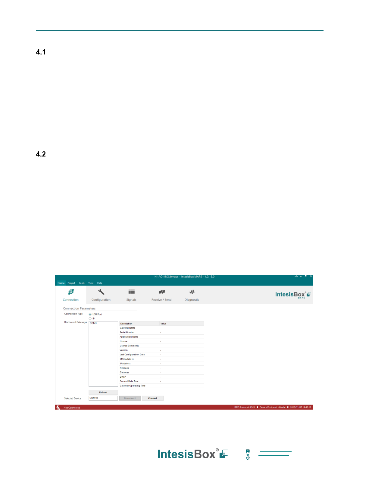
4.2.2 Connection
To configure the IntesisBox connection parameters press on the Connection button in the menu bar.
Figure 4.1 MAPS connection
Page 12

IntesisBox® KNX – HITACHI VRF User Manual r1.1 EN
12/30
This information is subject to change without prior notice
IntesisBox is a registered trademark of Intesis Software S.L.U.
email: info@intesisbox.com
web: www.intesisbox.com
phone: +34 938047134
4.2.3 Configuration tab
Select the Configuration tab to configure the connection parameters. Three subsets of information are shown in this
window: General (Gateway general parameters), KNX (KNX interface configuration) and Hitachi (Hitachi interface
parameters).
Figure 4.2 IntesisBox MAPS configuration tab
4.2.4 KNX configuration
Set parameters of KNX interface of IntesisBox.
Figure 4.3 IntesisBox MAPS KNX configuration tab
Page 13

IntesisBox® KNX – HITACHI VRF User Manual r1.1 EN
13/30
This information is subject to change without prior notice
IntesisBox is a registered trademark of Intesis Software S.L.U.
email: info@intesisbox.com
web: www.intesisbox.com
phone: +34 938047134
1. Device configuration
1.1. Physical Address. KNX physical address of the device in the network
1.2. Extended Addresses. Enables usage of KNX Extended addresses (range from 16/0/0 to 32/7/255).
2. Operating Mode. Settings related to KNX interface for control and feedback of AC unit’s operating mode.
2.1. KNX DPT for HVAC operation mode comm object. Base DPT. Base DPT to use for control/monitor the
operating mode. Following DPT types are offered:
o DPT_20.105. DPT_HVACContrMode: 0-Auto, 1-Heat, 3-Cool, 9-Fan, 14-Dry
o DPT_5.x (non-standarized): 0-Auto, 1-Heat, 2-Dry, 3-Fan, 4-Cool
2.2. KNX DPT for HVAC operation mode comm object. Extra DPT. Additional DPT to use for control/monitor
the operating mode.
o DPT_1.100. DPT_Heat/Cool: 0-Cool, 1-Heat.
o DPT_5.001. DPT_Scaling: Enables objects “Control_ Heat Mode & On” and “Control_ Cool Mode &
On”. Their type is DPT_Scaling (0..100%), and their ending is to be able to control parameters On/Off,
Cool/Heat of indoor unit from a single percentage object. They are meant to provide compatibility with
certain thermostats oriented to the operation of valves for Heating/Cooling. Whenever a value > 0% is
received at each of these two objects, the corresponding operating mode and ON operation is sent to
the indoor unit. Whenever both values are 0%, indoor unit is set to OFF
2.3. Use of 1-bit Operating Modes. 1-bit Control Objects. Enables a bit-type object for the control of each
operating mode.
2.4. Use of 1-bit Operating Modes. 1-bit Status Objects. Enables a bit-type object for monitoring each
operating mode.
3. Temperature Sensor.
3.1. Ambient temperature provided from KNX. Enables object Control_ KNX ambient temperature.
NOTE: Indoor unit does not accept, by itself, that an ambient temperature for control of operation
of the indoor unit is provided. To allow regulation of indoor unit according to a temperature reference
from KNX, what IntesisBox does is passing a different temperature setpoint to the indoor unit than
the one required by the user. The passed setpoint is such that the difference ‘Ambient temperature
reported by Hitachi IU – AC setpoint’ is equal to ‘Ambient temperature reported by KNX – AC
setpoint required by KNX’, using the following formula:
“AC Setp. Temp” = “AC Ret. Temp” - (“KNX Amb. Temp.” - “KNX Setp. Temp”)
Where:
▪ AC Setp. Temp: AC indoor unit setpoint temperature
▪ AC Ret. Temp: AC indoor unit return temperature
▪ KNX Amb. Temp.: Ambient temperature provided from KNX
▪ KNX Setp. Temp: Setpoint temperature provided from KNX
Consequently, when using this feature (Ambient temp provided from KNX), setpoint at AC and
setpoint in KNX will not necessarily be the same (actually, user will not be able to operate setpoint
from AC System controllers as the remote controller).
!
Page 14

IntesisBox® KNX – HITACHI VRF User Manual r1.1 EN
14/30
This information is subject to change without prior notice
IntesisBox is a registered trademark of Intesis Software S.L.U.
email: info@intesisbox.com
web: www.intesisbox.com
phone: +34 938047134
4. Fan Speed. Settings related to KNX interface for control and feedback of AC unit’s fan speed.
4.1. Auto Fan Speed. Configures availability of Auto Fan Speed control/monitoring objects. Necessary if your
indoor unit has auto fan speed.
4.2. KNX DPT for Fan Speed comm objects. DPT_5.001, DPT_Scaling. Control/monitoring of Fan Speed is
performed by means of scaling (percentage) objects. Thresholds for control object and values for status object
will vary according to number of fanspeeds of the unit.
4.2. KNX DPT for Fan Speed comm objects. DPT_5.010, DPT_Value_1_Ucount. Control/monitoring of Fan
Speed is performed by means of enumerated values.
4.4. Use of 1-bit Fan Speed. 1-bit Control Objects. Enables a bit-type object for control of fan speed.
4.5. Use of 1-bit Fan Speed. 1-bit Status Objects. Enables a bit-type object for monitoring of each fan speed.
5. Vanes Position. Settings related to KNX interface for control and feedback of AC unit’s vanes position.
4.1. Auto&Swing Vanes. Configures availability of Auto and Swing control/monitoring objects.
4.2. KNX DPT for Vane Position comm objects. DPT_5.001, DPT_Scaling. Control/monitoring of Vanes
Positions is performed by means of scaling (percentage) objects. Thresholds for control object and values for
status object will vary according to number of vanes positions of the unit.
4.2. KNX DPT for Vane Position comm objects. DPT_5.010, DPT_Value_1_Ucount. Control/monitoring of
Vanes Positions is performed by means of enumerated values.
4.4. Use of 1-bit Fan Speed. 1-bit Control Objects. Enables a bit-type object for control of Vanes Positions.
4.5. Use of 1-bit Fan Speed. 1-bit Status Objects. Enables a bit-type object for monitoring of each Vanes
Position.
Page 15

IntesisBox® KNX – HITACHI VRF User Manual r1.1 EN
15/30
This information is subject to change without prior notice
IntesisBox is a registered trademark of Intesis Software S.L.U.
email: info@intesisbox.com
web: www.intesisbox.com
phone: +34 938047134
4.2.5 Hitachi configuration
Set parameters for connection with Hitachi’s installation.
Figure 4.4 IntesisBox MAPS Hitachi configuration tab
In Units Configuration section you need to enter, for each unit:
• Active. If it’s active (checkbox at Unit xx), ranging from 1 to 64 indoor units that will be integrated (maximum
number of units will depend on IntesisBox model)
• IU address. Address 1..64 of Unit in Hitachi H-Link bus.
• OU address. Address 1..64 of Outdoor Unit in Hitachi H-Link bus.
• Description. Descriptive name to easy identification of the unit (for example, ‘living room floor 1 unit’, etc).
Additional to manual entry of each unit, autodiscover of present units in an H-Link installation is possible. To do so, click
button Scan. Following window will appear:
Page 16

IntesisBox® KNX – HITACHI VRF User Manual r1.1 EN
16/30
This information is subject to change without prior notice
IntesisBox is a registered trademark of Intesis Software S.L.U.
email: info@intesisbox.com
web: www.intesisbox.com
phone: +34 938047134
Figure 4.5 IntesisBox MAPS Scan Hitachi Units window
By pressing Scan button, connected Hitachi H-Link bus will be scanned for available units. Error window will appear if
there is a problem in the connection with H-Link bus (units not powered, bus not connected, …).
A progress bar will appear during the scan, which will take up to a few minutes. After scan is completed, detected units
will be shown in available units as follows:
Figure 4.6 IntesisBox MAPS Scan Hitachi Units window with scan results
Select with its checkbox units to add (or replace) in installation, according to selection Replace Units / Add Units.
After units to be integrated are selected, click button Apply, and changes will appear in previous Units Configuration
window.
Page 17

IntesisBox® KNX – HITACHI VRF User Manual r1.1 EN
17/30
This information is subject to change without prior notice
IntesisBox is a registered trademark of Intesis Software S.L.U.
email: info@intesisbox.com
web: www.intesisbox.com
phone: +34 938047134
Figure 4.7 IntesisBox MAPS Hitachi configuration tab after importing scan results
4.2.6 Signals
All available KNX objects, its corresponding description and other main parameters are listed in the signals tab.
Figure 4.8 IntesisBox MAPS Signals tab
Page 18

IntesisBox® KNX – HITACHI VRF User Manual r1.1 EN
18/30
This information is subject to change without prior notice
IntesisBox is a registered trademark of Intesis Software S.L.U.
email: info@intesisbox.com
web: www.intesisbox.com
phone: +34 938047134
4.2.7 Sending the configuration to IntesisBox
When the configuration is finished, follow the next steps.
1.- Save the project (Menu option Project->Save) on your hard disk (more information in IntesisBox MAPS User
Manual).
2.- Go to tab ‘Receive / Send’ of MAPS, and in Send section, press Send button. IntesisBox will reboot
automatically once the new configuration is loaded.
Figure 4.9 IntesisBox MAPS Receive/Send tab
After any configuration change, do not forget to send the configuration file to the IntesisBox using the
Send button in the Receive / Send section.
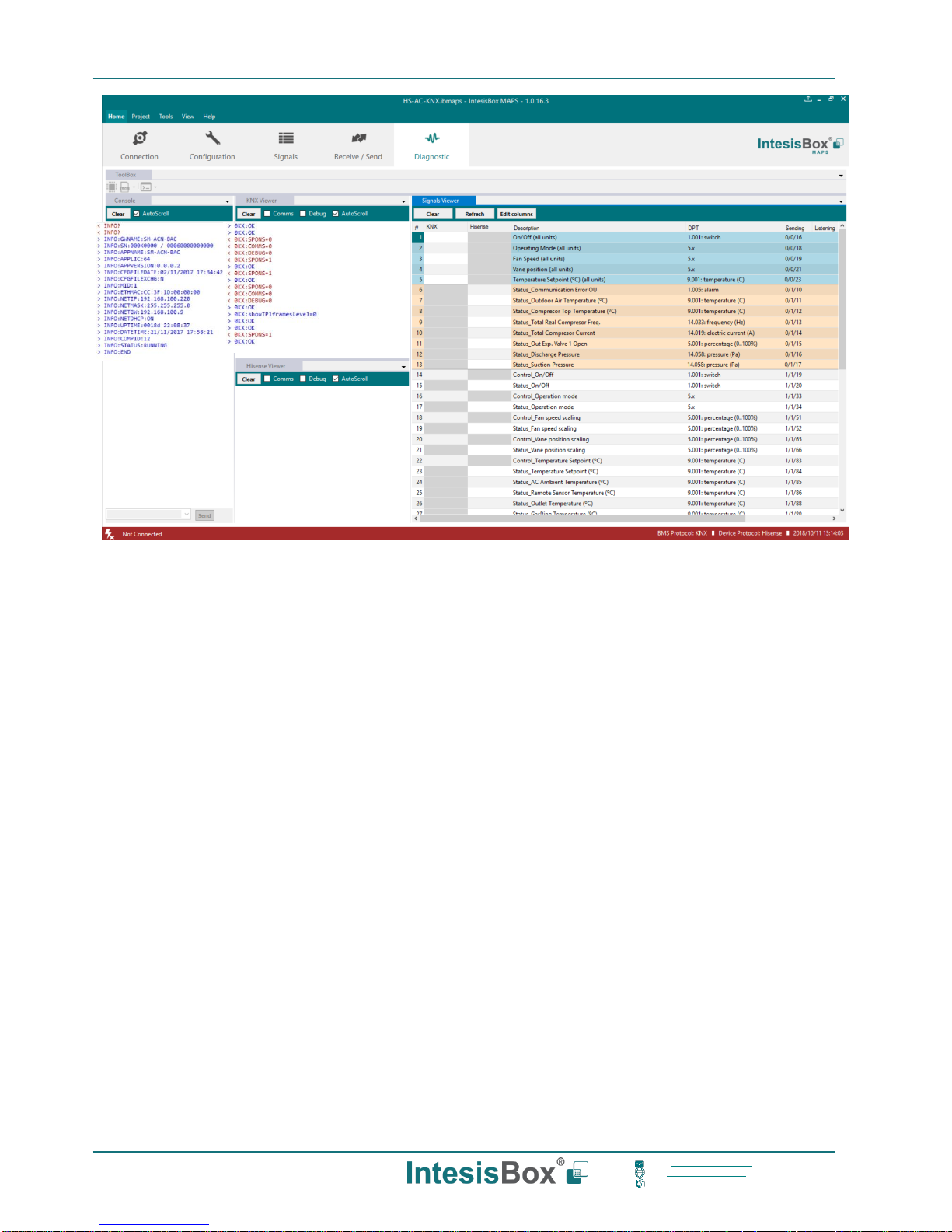
4.2.8 Diagnostic
To help integrators in the commissioning tasks and troubleshooting, the Configuration Tool offers some specific tools
and viewers.
In order to start using the diagnostic tools, connection with the Gateway is required.
The Diagnostic section is composed by two main parts: Tools and Viewers.
• Tools
Use the tools section to check the current hardware status of the box, log communications into
compressed files to be sent to the support, change the Diagnostic panels’ view or send commands to
the gateway.
• Viewers
In order to check the current status, viewer for the Internal and External protocols are available. It is
also available a generic Console viewer for general information about communications and the gateway
status and finally a Signals Viewer to simulate the BMS behavior or to check the current values in the
system.
Page 19
IntesisBox® KNX – HITACHI VRF User Manual r1.1 EN
19/30
This information is subject to change without prior notice
IntesisBox is a registered trademark of Intesis Software S.L.U.
email: info@intesisbox.com
web: www.intesisbox.com
phone: +34 938047134
Figure 4.10 Diagnostic
More information about the Diagnostic section can be found in the Configuration Tool manual.
Page 20

IntesisBox® KNX – HITACHI VRF User Manual r1.1 EN
20/30
This information is subject to change without prior notice
IntesisBox is a registered trademark of Intesis Software S.L.U.
email: info@intesisbox.com
web: www.intesisbox.com
phone: +34 938047134
4.2.9 Set-up procedure
1. Install IntesisBox MAPS on your laptop, use the setup program supplied for this and follow the instructions given by
the Installation wizard.
2. Install IntesisBox in the desired installation site. Installation can be on DIN rail or on a stable not vibrating surface
(DIN rail mounted inside a metallic industrial cabinet connected to ground is recommended).
3. Connect the KNX communication cable coming from the KNX network to the port marked as Port A on IntesisBox
(More details in section 3).
4. Connect the communication cable coming from the Hitachi H-Link installation to the port marked as Port B of
IntesisBox (More details in section 3).
5. Power up IntesisBox. The supply voltage can be 9 to 36 Vdc or just 24 Vac. Take care of the polarity of the supply
voltage applied.
WARNING! In order to avoid earth loops that can damage IntesisBox and/or any other equipment connected to
it, we strongly recommend:
• The use of DC power supplies, floating or with the negative terminal connected to earth. Never use a DC
power supply with the positive terminal connected to earth.
• The use of AC power supplies only if they are floating and not powering any other device.
6. If you want to connect using IP, connect the Ethernet cable from the laptop PC to the port marked as Ethernet of
IntesisBox (More details in section 3).
If you want to connect using USB, connect the USB cable from the laptop PC to the port marked as Console of
IntesisBox (More details in section 3).
7. Open IntesisBox MAPS, create a new project selecting a copy of the one named IBOX-KNX-HI.
8. Modify the configuration as desired, save it and download the configuration file to IntesisBox as explained in the
IntesisBox MAPS user manual.
9. Visit the Diagnostic section and check that there is communication activity, some TX frames and some other RX
frames. This means that the communication with the KNX installation and Hitachi installation is OK. In case there is
no communication activity between IntesisBox and the KNX side and/or Hitachi units, check that those are operative:
check communication cable used to connect all devices and any other communication parameter.
Figure 4.11 Enable COMMS
Page 21

IntesisBox® KNX – HITACHI VRF User Manual r1.1 EN
21/30
This information is subject to change without prior notice
IntesisBox is a registered trademark of Intesis Software S.L.U.
email: info@intesisbox.com
web: www.intesisbox.com
phone: +34 938047134
5 Electrical & Mechanical Features
Enclosure
Plastic, type PC (UL 94 V-0)
Net dimensions (dxwxh): 90x88x56 mm
Recommended space for installation (dxwxh): 130x100x100mm
Color: Light Grey. RAL 7035
Battery
Size: Coin 20mm x 3.2mm
Capacity: 3V / 225mAh
Type: Manganese Dioxide Lithium
Mounting
Wall.
DIN rail EN60715 TH35.
Console Port
Mini Type-B USB 2.0 compliant
1500VDC isolation
Terminal Wiring
(for power supply and
low-voltage signals)
Per terminal: solid wires or stranded wires (twisted or with
ferrule)
1 core: 0.5mm2… 2.5mm2
2 cores: 0.5mm2… 1.5mm2
3 cores: not permitted
USB port
Type-A USB 2.0 compliant
Only for USB flash storage device
(USB pen drive)
Power consumption limited to 150mA
(HDD connection not allowed)
Power
1 x Plug-in screw terminal block (3 poles)
9 to 36VDC +/-10%, Max.: 140mA.
24VAC +/-10% 50-60Hz, Max.: 127mA
Recommended: 24VDC
Push Button
Button A: Check the user manual
Button B: Check the user manual
Operation
Temperature
0°C to +60°C
Ethernet
1 x Ethernet 10/100 Mbps RJ45
2 x Ethernet LED: port link and activity
Operational
Humidity
5 to 95%, no condensation
Port A
1 x KNX TP-1 Plug-in screw terminal block orange (2 poles)
2500VDC isolation from other ports
KNX power consumption: 5mA
Voltage rating: 29VDC
1 x Plug-in screw terminal block green (2 poles)
Reserved for future use
Protection
IP20 (IEC60529)
LED
Indicators
10 x Onboard LED indicators
2 x Run (Power)/Error
2 x Ethernet Link/Speed
2 x Port A TX/RX
2 x Port B TX/RX
1 x Button A indicator
1 x Button B indicator
Switch A
(SWA)
1 x DIP-Switch for PORT A configuration:
Reserved for future use
PORT B
1 x Serial EIA232 (SUB-D9 male connector)
Reserved for future use
1 x H-Link Plug-in screw terminal block (3 poles)
1500VDC isolation from other ports
Switch B
(SWB)
1 x DIP-Switch for PORT B configuration:
Reserved for future use (leave OFF, default)
Page 22
IntesisBox® KNX – HITACHI VRF User Manual r1.1 EN
22/30
This information is subject to change without prior notice
IntesisBox is a registered trademark of Intesis Software S.L.U.
email: info@intesisbox.com
web: www.intesisbox.com
phone: +34 938047134
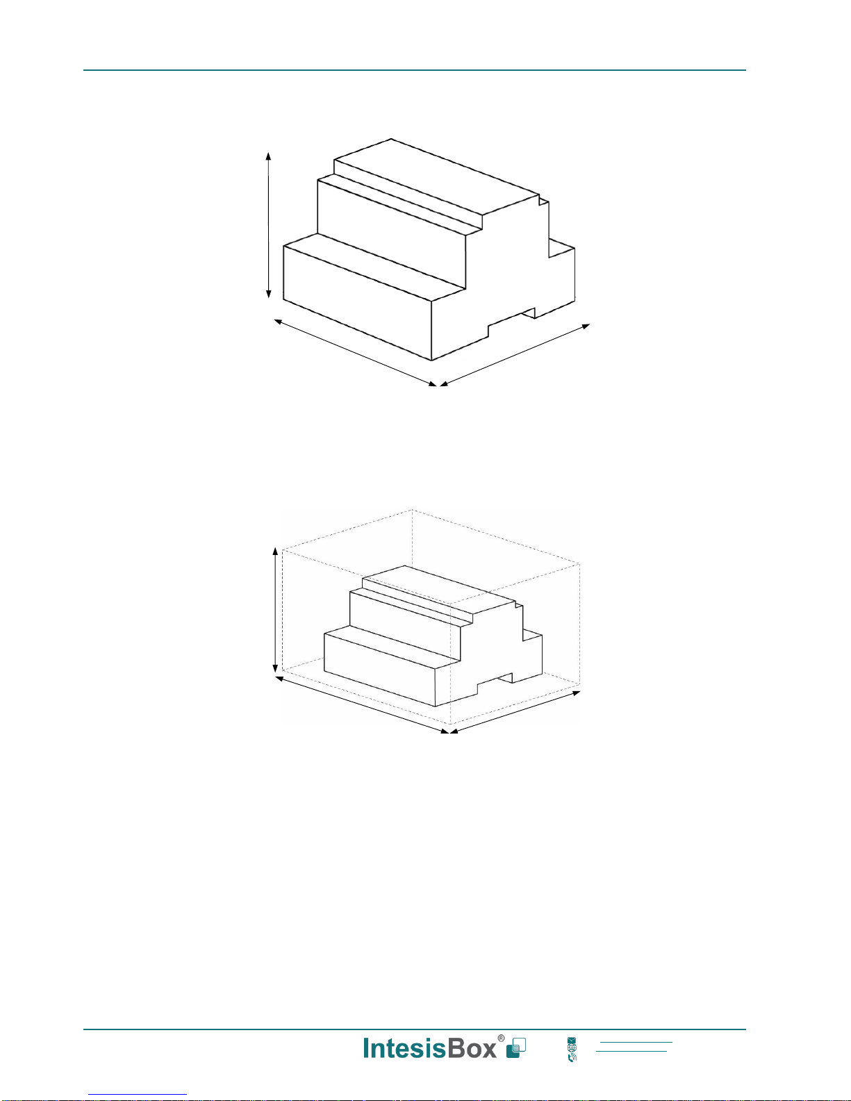
6 Dimensions
Recommended available space for its installation into a cabinet (wall or DIN rail mounting), with space enough for
external connections
100 mm (h)
100 mm (w)
130 mm (d)
56 mm (h)
88 mm (w)
90 mm (d)
Page 23

IntesisBox® KNX – HITACHI VRF User Manual r1.1 EN
23/30
This information is subject to change without prior notice
IntesisBox is a registered trademark of Intesis Software S.L.U.
email: info@intesisbox.com
web: www.intesisbox.com
phone: +34 938047134
7 AC Unit Types compatibility
A list of Hitachi unit model references compatible with HI-AC-KNX-16/64 and their available features can be found in:
http://intesis.com/pdf/IntesisBox_HI-AC-xxx-MIU_AC_Compatibility.pdf
Page 24
IntesisBox® KNX – HITACHI VRF User Manual r1.1 EN
24/30
This information is subject to change without prior notice
IntesisBox is a registered trademark of Intesis Software S.L.U.
email: info@intesisbox.com
web: www.intesisbox.com
phone: +34 938047134
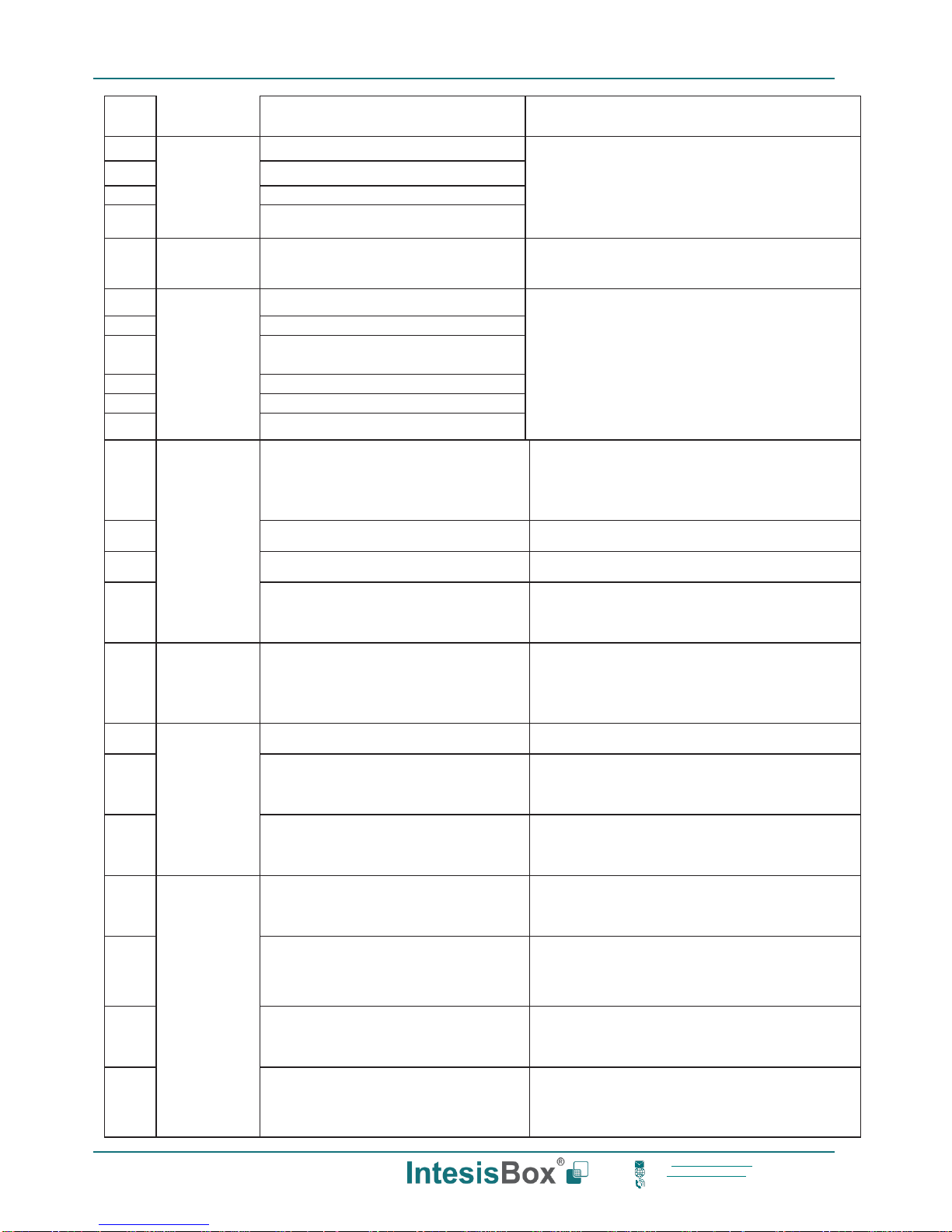
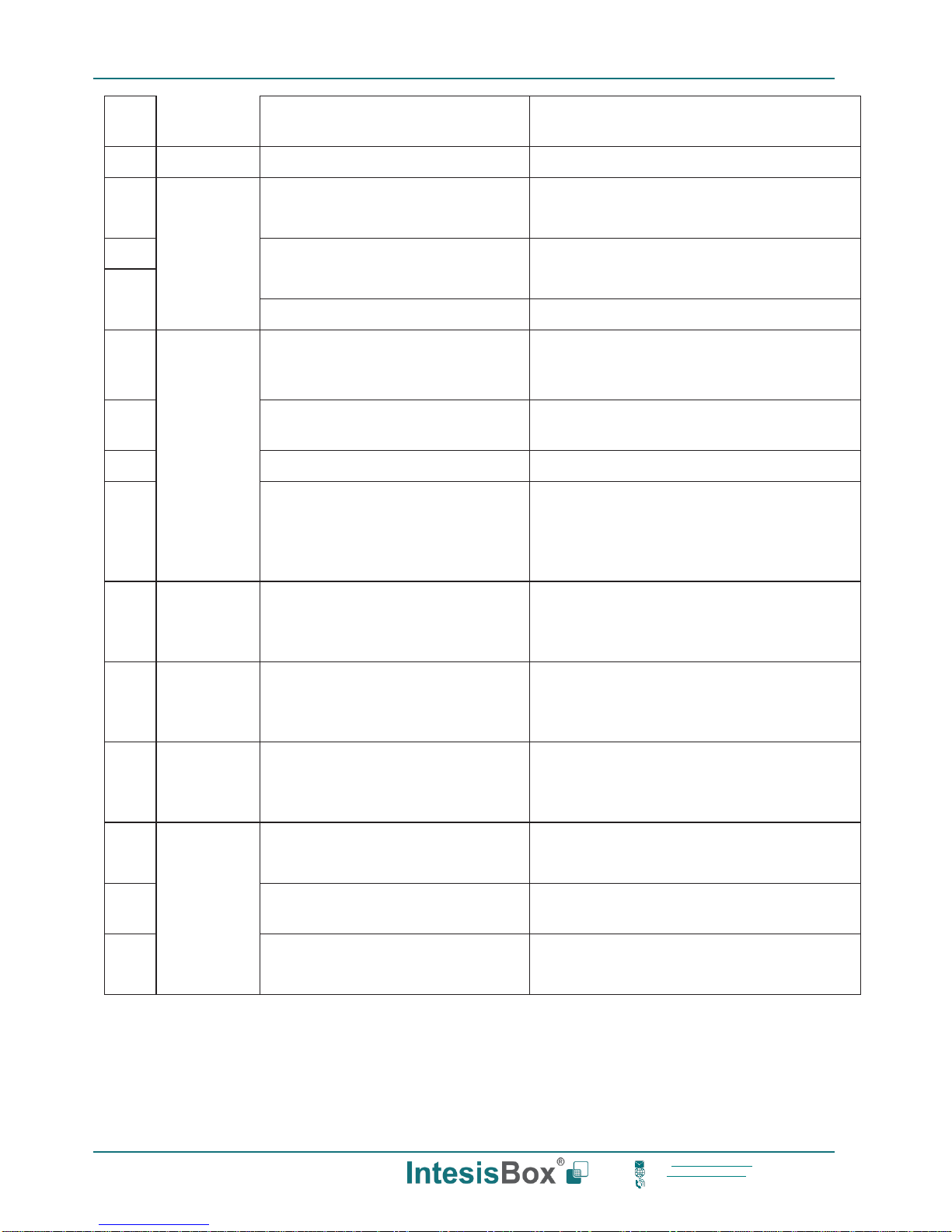
8 Error codes for Indoor and Outdoor Units
This list contains all possible values shown in KNX Object for “Error Code” for each indoor unit and outdoor unit.
It must be taken into account that Outdoor Units are only able to reflect a single error for each indoor / outdoor unit in
the system. Thus, a unit having two or more active errors from that list will only report a single error code – the one of
the first error that has been detected.
Error
Code
Category
Content of Abnormality
Leading Cause
01
lndoor Unit
Activation of Protection Device (Float
Switch)
Activation of Float Switch
(High Water Level in Drain Pan,
Abnormality of Drain Pipe, Float Switch or
Drain Pan)
02
Outdoor Unit
Activation of Protection
Device (High Pressure
Cut)
Activation of PSH (Pipe Clogging,
Excessive Refrigerant! lnert Gas
Mixing)
03
Transmission
Abnormality between lndoor and
Outdoor
incorrect Wiring, Loose Terminals,
Disconnect Wire, Blowout of Fuse,
Outdoor Unit Power OFF
04
Abnormality between lnverter PCB
and Outdoor PCB
lnverter PCB - Outdoor PCB
Transmission Failure (Loose Connector,
Wire Breaking, Blowout of Fuse)
04.
Abnormality between Fan Controller
and Outdoor PCB
Fan Controller - Outdoor PCB
Transmission Failure (Loose Connector,
Wire Breaking, Blowout of Fuse)
05
Supply Phase
Abnormality Power Source Phases
lncorrect Power Source,
Connection to Reversed
Phase, Open-Phase
06
Voltage
Abnormal lnverter Voltage
Outdoor Voltage Drop, insufficient Power
Capacity
06. Abnormal Fan Controller Voltage
Outdoor Voltage Drop, lnsufficient Power
Capacity
07
Cycle
Decrease in Discharge Gas Superheat
Excessive Refrigerant! Charge, Failure of
Thermistor, lncorrect Wiring, lncorrect
Piping Connection, Expansion Valve
Locking at Opened Position (Disconnect
Connector)
08
lncrease in Discharge Gas
Temperature
lnsufficient Refrigerant! Charge,
Pipe Clogging, Failure of
Thermistor, lncorrect Wiring,
lncorrect Piping Connection, Expansion
Valve Locking at Closed Position
(Disconnect Connector)
0A
Transmission
Abnormality between Outdoor and
Outdoor
lncorrect Wiring, Breaking Wire, Loose Terminals
0b
Outdoor Unit
lncorrect Outdoor Unit Address
Setting
Duplication of Address Setting for
Outdoor Units (Sub Units) in Same
Refrigerant! Cycle System
0c
lncorrect Outdoor Unit Main Unit
Two (or more) Outdoor Units Set
Page 25
IntesisBox® KNX – HITACHI VRF User Manual r1.1 EN
25/30
This information is subject to change without prior notice
IntesisBox is a registered trademark of Intesis Software S.L.U.
email: info@intesisbox.com
web: www.intesisbox.com
phone: +34 938047134
Setting
as "Main Unit" Exist in Same
Refrigerant! Cycle System
11
Sensoron
lndoor Unit
lnlet Air Thermistor
lncorrect Wiring,
Disconnecting Wiring Breaking
Wire, Short Circuit
12
Outlet Air Thermistor
13
Freeze Protection Thermistor
14
Gas Piping Thermistor
19
Fan Motor
Activation of Protection Device for
lndoor Fan
Fan Motor Overheat, Locking
21
Sensor on
Outdoor Unit
High Pressure Sensor
lncorrect Wiring,
Disconnecting Wiring Breaking
Wire, Short Circuit
22
Outdoor Air Thermistor
23
Discharge Gas Thermistor on Top of
Compressor
24
Heat Exchanger Liquid Pipe Thermistor
25
Heat Exchanger Gas Pipe Thermistor
29
Low Pressure Sensor
31
System
lncorrect Capacity Setting of Outdoor
Unit and lndoor Unit
lncorrect Capacity Code Setting of Combination
Excessive or lnsufficient lndoor Unit Total
Capacity Code
35
lncorrect Setting of lndoor Unit No.
Duplication of lndoor Unit No. in same Ref. Gr.
36
lncorrect of lndoor Unit Combination
lndoor Unit is Designed for R22
38
Abnormality of Picking up Circuit for
Protection in Outdoor Unit
Failure of Protection Detecting Device
(lncorrect Wiring of Outdoor PCB)
39 Compressor
Abnormality Running Current at
Constant! Speed Compressor
Overcurrent, Blowout Fuse, Current Sensor
Failure, instantaneous Power Failure, Voltage
Drop, Abnormal Power Supply
3A
Outdoor Unit
Abnormality of Outdoor Unit Capacity
Outdoor Unit Capacity > 510kBtu/h
3b
lncorrect Setting of Outdoor Unit
Models Combination or Voltage
lncorrect Setting of Main and Sub Unit(s)
Combination or Voltage
3d
Abnormality Transmission between
Main Unit and Sub Unit(s)
lncorrect Wiring, Disconnect Wire, Breaking Wire,
PCB Failure
43
Protection
Device
Activation of Low Compression Ratio
Protection Device
Defective Compression (Failure of Compressor of
lnverter, Loose Power Supply Connection)
44
Activation of Low Pressure lncrease
Protection Device
Overload at Cooling, High Temperature at
Heating, Expansion Valve Locking (Loose
Connector)
45
Activation of High Pressure lncrease
Protection Device
Overload Operation (Clogging, Short-Pass), Pipe
Clogging, Excessive Refrigerant!, lnert Gas Mixing
47
Activation of Low Pressure Decrease
Protection Device (Vacuum Operation
Protection)
lnsuffcient Refrigerant!, Refrigerant! Piping,
Clogging, Expansion Valve Locking at Open
Position (Loose Connector)
Page 26
IntesisBox® KNX – HITACHI VRF User Manual r1.1 EN
26/30
This information is subject to change without prior notice
IntesisBox is a registered trademark of Intesis Software S.L.U.
email: info@intesisbox.com
web: www.intesisbox.com
phone: +34 938047134
48
Activation of lnverter Overcurrent
Protection Device
Overload Operation, Compressor Failure
51
Sensor
Abnormal lnverter Current! Sensor
Current! Sensor Failure
53
lnverter
lnverter Error Signal Detection
Driver IC Error Signal Detection (Protection for
Overcurrent, Low Voltage, Short Circuit)
54
Abnormality of lnverter Fin
Temperature
Abnormal lnverter Fin Thermistor,
Heat Exchanger Clogging, Fan Motor Failure
55
lnverter Failure
lnverter PCB Failure
57
Fan Controller
Activation of Fan Controller Protection
Driver IC Error Signal Detection (Protection for
Overcurrent, Low Voltage, Short Circuit),
lnstantaneous Overcurrent
5A
Abnormality of Fan Controller Fin
Temperature
Fin Thermistor Failure, Heat Exchanger Clogging,
Fan Motor Failure
5b
Activation of Overcurrent Protection
Fan Motor Failure
5C Abnormality of Fan Controller Sensor
Failure of Current! Sensor (lnstantaneous
Overcurrent,
lncrease of Fin Temperature, Low Voltage, Earth
Fault, Step-Out)
EE Compressor
Compressor Protection Alarm
(lt is cannot be reset from remote
Controller)
This alarm code appears when the following
alarms• occurs three times within 6 hours.
*02, 07, 08, 39, 43 to 45, 47
b1
Outdoor Unit
No. Setting
lncorrect Setting of Unit and
Refrigerant! Cycle No.
Over 64 Number is Set for Address or Refrigerant!
Cycle.
b5
lndoor Unit
No. Setting
lncorrect lndoor Unit Connection
Number Setting
More than 17 Non-Corresponding to Hi-NET Units
are Connected to One System.
C1
Switch Box
Unit
lncorrect lndoor Unit Connection
2 or more Switch Box Units are connected
between outdoor unit and indoor unit.
C2
lncorrect lndoor Unit Connection No.
Setting
9 or More lndoor Units Connected to Switch Box
Unit
C3 lncorrect lndoor Unit Connection
The indoor units of different refrigerant! cycle is
connected to Switch Box unit.
Page 27
IntesisBox® KNX – HITACHI VRF User Manual r1.1 EN
27/30
This information is subject to change without prior notice
IntesisBox is a registered trademark of Intesis Software S.L.U.
email: info@intesisbox.com
web: www.intesisbox.com
phone: +34 938047134
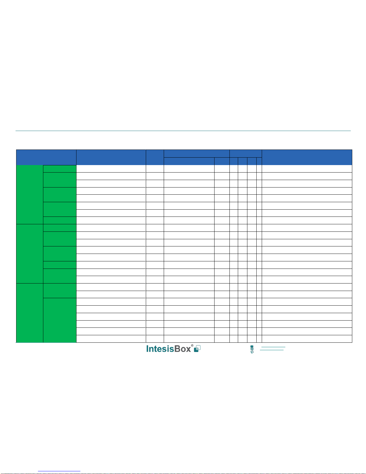
9 Appendix A – Communication Objects Table
TOPIC
NAME
LEN
DATAPOINT TYPE
FLAGS
FUNCTION
DPT_NAME
DPT_ID R W T U
GLOBAL
SIGNALS
ON/OFF
On/Off (all units)
1 bit
DPT_Switch
1.001 W
0-Off, 1-On
OP MODE
Operating Mode (all units)
1 byte
DPT_HVACContrMode
20.105 W
0-Auto, 1-Heat, 3-Cool, 9-Fan, 14-Dry
Operating Mode (all units)
1 byte
Non-standarized
5.x W
0-Auto, 1-Heat, 2-Dry, 3-Fan, 4-Cool
FAN SPEED
Fan Speed (all units)
1 byte
Non-standarized
5.x W
1-Low, 2-Mid, 3-High, 4-High+
Fan Speed AUTO (all units)
1 bit
DPT_Switch
1.001 W
1-Set auto fan; 0-Stop auto fan
VANE POSITION
Vane position (all units)
1 byte
Non-standarized
5.x W
1-Position 1...7-Position 7
Vane position AUTO (all units)
1 bit
DPT_Switch
1.001 W
1-Set auto vane; 0-Stop auto vane
SETP TEMP
Temperature Setpoint (ºC) (all units)
2 byte
DPT_Value_Temp
9.001 W
Cool:19..30 ºC; Heat:17..30 ºC
OUTDOOR
UNIT
SIGNALS
COMM ERROR
Status_Communication Error OU
1 bit
DPT_Alarm
1.005 R T
0-No error, 1-Error
TEMPERATURES
Status_Outdoor Air Temperature (ºC)
2 byte
DPT_Value_Temp
9.001 R T
-50..99 ºC
Status_Compresor Top Temperature (ºC)
2 byte
DPT_Value_Temp
9.001 R T
0..200 ºC
COMPRESOR
Status_Total Real Compresor Freq.
4 byte
DPT_Value_Frequency
14.033 R T
0..255 Hz
Status_Total Compresor Current
4 byte
DPT_Value_Electric_Current
14.019 R T
0..255 A
VALVE
Status_Out Exp. Valve 1 Open
1 byte
DPT_Scaling
5.001 R T
0..100 %
PRESSURE
Status_Discharge Pressure
4 byte
DPT_Value_Pressure
14.058 R T
-5.0..9.9 Mpa
Status_Suction Pressure
4 byte
DPT_Value_Pressure
14.058 R T
-5.0..9.9 Mpa
ON / OFF
Control _On/Off
1 bit
DPT_Switch
1.001 W
0-Off,1-On
Status _On/Off
1 bit
DPT_Switch
1.001 R T
0-Off,1-On
OP MODE
Control _Operation mode
1 byte
DPT_HVACContrMode
20.105 W
0-Auto, 1-Heat, 3-Cool, 9-Fan, 14-Dry
Status _Operation mode
1 byte
DPT_HVACContrMode
20.105 R T
0-Auto, 1-Heat, 3-Cool, 9-Fan, 14-Dry
Control _Operation mode
1 byte
Non-standarized
5.x W
0-Auto, 1-Heat, 2-Dry, 3-Fan, 4-Cool
Status _Operation mode
1 byte
Non-standarized
5.x R T
0-Auto, 1-Heat, 2-Dry, 3-Fan, 4-Cool
Control _Mode Cool/Heat
1 bit
DPT_Heat/Cool
1.100 W
0-Cool, 1-Heat
Status _Mode Cool/Heat
1 bit
DPT_Heat/Cool
1.100 R T
0-Cool, 1-Heat
Page 28

IntesisBox® KNX – HITACHI VRF User Manual r1.1 EN
28/30
This information is subject to change without prior notice
IntesisBox is a registered trademark of Intesis Software S.L.U.
email: info@intesisbox.com
web: www.intesisbox.com
phone: +34 938047134
INDOOR UNIT
SIGNALS
Control _Heat mode&ON
1 byte
DPT_Scaling
5.001 W
0%-Off, 1%-100%-On+Heat
Control _Cool mode&ON
1 byte
DPT_Scaling
5.001 W
0%-Off, 1%-100%-On+Cool
Control _Auto mode
1 bit
DPT_Switch
1.001 W
1-Set auto mode
Status _Auto mode
1 bit
DPT_Switch
1.001 R T
1-Auto mode active, 0-Auto mode not active
Control _Heat mode
1 bit
DPT_Switch
1.001 W
1-Set heat mode
Status _Heat mode
1 bit
DPT_Switch
1.001 R T
1-Heat mode active, 0-Heat mode not active
Control _Cool mode
1 bit
DPT_Switch
1.001 W
1-Set cool mode
Status _Cool mode
1 bit
DPT_Switch
1.001 R T
1-Cool mode active, 0-Cool mode not active
Control _Fan mode
1 bit
DPT_Switch
1.001 W
1-Set fan mode
Status _Fan mode
1 bit
DPT_Switch
1.001 R T
1-Fan mode active, 0-Fan mode not active
Control _Dry mode
1 bit
DPT_Switch
1.001 W
1-Set dry mode
Status _Dry mode
1 bit
DPT_Switch
1.001 R T
1-Dry mode active, 0-Dry mode not active
Control_Fan speed enumerated
1 byte
Non-standarized
5.x W
1-Low, 2-Mid, 3-High, 4-High+
FAN SPEED
Status _Fan speed enumerated
1 byte
Non-standarized
5.x R T
1-Low, 2-Mid, 3-High, 4-High+
Control _Fan speed scaling
1 byte
DPT_Scaling
5.001 W
Thersholds (0%..37%; 38%..62%; 63%..87%;
Status _Fan speed scaling
1 byte
DPT_Scaling
5.001 R T
Thersholds (25%; 50%; 75%; 100%)
Control_ Fan speed low
1 bit
DPT_Switch
1.001 W
1-Set fan speed low
Status_Fan speed low
1 bit
DPT_Switch
1.001 R T
1-Speed low active, 0-Speed low not active
Control_Fan speed mid
1 bit
DPT_Switch
1.001 W
1-Set fan speed mid
Status_Fan speed mid
1 bit
DPT_Switch
1.001 R T
1-Speed mid active, 0-Speed mid not active
Control_Fan speed high
1 bit
DPT_Switch
1.001 W
1-Set fan speed high
Status_Fan speed high
1 bit
DPT_Switch
1.001 R T
1-Speed high active, 0-Speed high not active
Control_Fan speed high+
1 bit
DPT_Switch
1.001 W
1-Set fan speed high+
Status_Fan speed high+
1 bit
DPT_Switch
1.001 R T
1-Speed high+ active, 0-Speed high+ not active
Control_Fan speed Man/Auto
1 bit
DPT_Switch
1.001 W
0-Manual; 1-Auto
Status_Fan speed Man/Auto
1 bit
DPT_Switch
1.001 R T
0-Manual; 1-Auto
VANE POS
Control_Vane position enumerated
1 byte
Non-standarized
5.x W
1-Position 1..7-Position 7
Page 29
IntesisBox® KNX – HITACHI VRF User Manual r1.1 EN
29/30
This information is subject to change without prior notice
IntesisBox is a registered trademark of Intesis Software S.L.U.
email: info@intesisbox.com
web: www.intesisbox.com
phone: +34 938047134
INDOOR UNIT
SIGNALS
Status_Vane position enumerated
1 byte
Non-standarized
5.x R T
1-Position 1..7-Position 7
Control_Vane position scaling
1 byte
DPT_Scaling
5.001 W
Thersholds(0..21%;22..36%;37..50%;51..64%;65..79%;8
Status_Vane position scaling
1 byte
DPT_Scaling
5.001 R T
Thersholds(0..14%;15..29%;30..43%;44..57%;58..71%;7
Control_Vane position auto
1 bit
DPT_Switch
1.001 R T
1-Set auto vane, 0-Stop auto vane
Status_Vane position auto
1 bit
DPT_Switch
1.001 W
1-Vane auto active, 0-Vane auto not active
Control_Vane position position-1
1 bit
DPT_Switch
1.001 R T
1-Set position-1 vane
Status_Vane position position-1
1 bit
DPT_Switch
1.001 W
1-Vane position-1 active, 0-Vane position-1 not active
Control_Vane position position-2
1 bit
DPT_Switch
1.001 R T
1-Set position-2 vane
Status_Vane position position-2
1 bit
DPT_Switch
1.001 W
1-Vane position-2 active, 0-Vane position-2 not active
Control_Vane position position-3
1 bit
DPT_Switch
1.001 R T
1-Set position-3 vane
Status_Vane position position-3
1 bit
DPT_Switch
1.001 W
1-Vane position-3 active, 0-Vane position-3 not active
Control_Vane position position-4
1 bit
DPT_Switch
1.001 R T
1-Set position-4 vane
Status_Vane position position-4
1 bit
DPT_Switch
1.001 W
1-Vane position-4 active, 0-Vane position-4 not active
Control_Vane position position-5
1 bit
DPT_Switch
1.001 R T
1-Set position-5 vane
Status_Vane position position-5
1 bit
DPT_Switch
1.001 W
1-Vane position-5 active, 0-Vane position-5 not active
Control_Vane position position-6
1 bit
DPT_Switch
1.001 R T
1-Set position-6 vane
Status_Vane position position-6
1 bit
DPT_Switch
1.001 W
1-Vane position-6 active, 0-Vane position-6 not active
Control_Vane position position-7
1 bit
DPT_Switch
1.001 R T
1-Set position-7 vane
Status_Vane position position-7
1 bit
DPT_Switch
1.001 W
1-Vane position-7 active, 0-Vane position-7 not active
TEMPERATURES
Control_Temperature Setpoint (ºC)
2 byte
DPT_Value_Temp
9.001 W
Cool:19..30 ºC; Heat:17..30 ºC
Status_Temperature Setpoint (ºC)
2 byte
DPT_Value_Temp
9.001 R T
Cool:19..30 ºC; Heat:17..30 ºC
Status_AC Ambient Temperature (ºC)
2 byte
DPT_Value_Temp
9.001 R T
-63..63 ºC
Status_Remote Sensor Temperature (ºC)
2 byte
DPT_Value_Temp
9.001 R T
-63..63 ºC
Control_KNX ambient Temperature (ºC)
2 byte
DPT_Value_Temp
9.001 W
ºC
Status_Outlet Temperature (ºC)
2 byte
DPT_Value_Temp
9.001 W
-63..63 ºC
Status_GasPipe Temperature (ºC)
2 byte
DPT_Value_Temp
9.001 R T
-63..63 ºC
Status_LiquidPipe Temperature (ºC)
2 byte
DPT_Value_Temp
9.001 W
-63..63 ºC
Page 30

IntesisBox® KNX – HITACHI VRF User Manual r1.1 EN
30/30
This information is subject to change without prior notice
IntesisBox is a registered trademark of Intesis Software S.L.U.
email: info@intesisbox.com
web: www.intesisbox.com
phone: +34 938047134
INDOOR UNIT
SIGNALS
ERROR CODE
Status_Unit error
1 bit
1.005-DPT_Alarm
1.005 R T
0-No error, 1-Error
Status_Unit error code
2 byte
Non-standarized
8.x R T
0-No Error, X-Error (100..999)
FILTER
Status_FilterSign
1 bit
DPT_Alarm
1.005 R T
0-Normal, 1-Alarm
Control _FilterReset
1 bit
DPT_Reset
1.015 W
0-No reset, 1-Reset
COMM STATUS
Status_Communication status
1 bit
DPT_Switch
1.001 R T
0-Not exist, 1-Exist
REMOC.
Control_On/Off Remote controll
disablement
1 bit
DPT_Bool
1.002 W
0-No disabled, 1-Disabled
Status_On/Off Remote controll
disablement
1 bit
DPT_Bool
1.002 R T
0-No disabled, 1-Disabled
Control_Mode Remote controll
disablement
1 bit
DPT_Bool
1.002 W
0-No disabled, 1-Disabled
Status_Mode Remote controll disablement
1 bit
DPT_Bool
1.002 R T
0-No disabled, 1-Disabled
Control_Setpoint Remote controll
disablement
1 bit
DPT_Bool
1.002 W
0-No disabled, 1-Disabled
Status_Setpoint Remote controll
disablement
1 bit
DPT_Bool
1.002 R T
0-No disabled, 1-Disabled
Control_Fan Remote controll disablement
1 bit
DPT_Bool
1.002 W
0-No disabled, 1-Disabled
Status_Fan Remote controll disablement
1 bit
DPT_Bool
1.002 R T
0-No disabled, 1-Disabled
SYSTEM INFO
Status_Unit type
1 byte
DPT_Value_1_Ucount
5.010 R T
1-SS, 2-FC, 3-VRF, 4-IU, 5-ES, 13-Not Defined
Status_Unit adress
1 byte
DPT_Value_1_Ucount
5.010 R T
1..64
Status_System adress
1 byte
DPT_Value_1_Ucount
5.010 R T
1..64
DEHUMIDIFICATION
Status_Dehumidification
1 bit
DPT_Switch
1.001 R T
0-Off,1-On
Control_Dehumidification correction
1 byte
DPT_Value_1_Ucount
5.010 W
0..2
Status_Dehumidification correction
1 byte
DPT_Value_1_Ucount
5.010 R T
0..2
OTHERS
Status_Compresor stop cause
2 byte
Non-standarized
8.x R T
X-Cause (0-254), 255-Operation Off
Status_Expansion valve open
1 byte
DPT_Scaling
5.001 R T
0..100 %
Status_Operation condition
1 byte
Non-standarized
5.x R T
0-Off, 1-Thermo Off, 2-Thermo On, 3-Alarm
Status_RC SW Temperature (ºC)
2 byte
DPT_Value_Temp
9.001 R T
-63..63 ºC
Status_RC SW Configuration
1 bit
DPT_Switch
1.001 R T
0-Without RCS, 1-With RCS
 Loading...