

Page 1
Interfaz DK-RC-MBS-1 FW:1.6
Interface DK-RC-MBS-1 FW:1.6
1 / 2
© Intesis Software S.L.U. - Todos los derechos reservados/ All rights reserved
IntesisBox es una marca registrada de / is a registred trademark of Intesis Software SLU
La información en este documento puede variar sin previo aviso. / This information is subject to change without notice.
Doc. Rev 3.5
URL
email
Phone
http://www.intesisbox.com
info@intesisbox.com
+34 938047134
• Esta interfaz debe ser instalada por personal técnico
acreditado (electricista, instalador o personal técnico
cualificado) y siguiendo todas las instrucciones de
seguridad.
• La interfaz debe ser instalada en una ubicación con acceso
restringido.
• Antes de manipular en el interior del aire acondicionado,
asegúrese de que está completamente desconectado de la
red eléctrica.
• En caso de instalación mural de la interfaz junto a la unidad
interior de aire acondicionado, fije la interfaz de forma
segura siguiendo las instrucciones del diagrama de abajo.
• This interface must be installed by accredited technical
personnel (electrician, installer or qualified technical
personnel) and they must follow all the safety instructions.
• This interface must be installed in an acces restricted
location
• Before manipulating the AC indoor unit, make sure it is
completely disconnected from Mains Power.
• In case of wall mounting of the interface next to the AC
indoor unit, attach the interface safely following the
instructions of the diagram below.
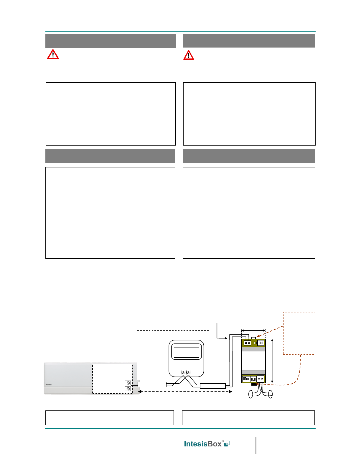
• Desconecte el aire acondicionado de la red eléctrica.
• Fije la interfaz a la pared junto a la unidad interior del aire
acondicionado siguiendo las instrucciones del diagrama de
abajo o dentro de la unidad interior del aire acondicionado
(respete las instrucciones de seguridad anteriores).
• Conecte el interfaz al bus P1P2 en cualquier punto del
mismo. El bus P1P2 es el bus que conecta la unidad interior
de aire acondicionado y el Control Remoto por cable. Son
un par de hilos que se conectan a los terminales P1P2. Este
bus no tiene polaridad.
• Conecte el bus EIA-485 al conector EIA485 de la interfaz.
Respete la polaridad.
• Tape la unidad interior del aire acondicionado y vuelva a
conectarla a la red eléctrica.
• Siga las instrucciones del Manual de Usuario para la
configuración y puesta en servicio de la interfaz.
• Siga las instrucciones de la página siguiente para
configurar la interfaz a través de los micro interruptores.
• Disconnect the air conditioning from the Mains Power.
• Attach the interface next to the AC indoor unit (wall
mounting) following the instructions of the diagram below or
install it inside the AC indoor unit (respect the safety
instructions given above).
• Connect the interface to the P1P2 bus in any point of the
bus. The P1 P2 bus is the bus that connects the AC indoor
unit and the wired Remote Controller. It is a two-wire bus
connecting terminals P1P2. This P1P2 connection has no
specific polarity.
• Connect the EIA-485 bus to the connector EIA485 of the
interface.
• Close the AC indoor unit and reconnect it to Mains Power.
• Follow the instructions on the User’s Manual to configure
and commission the interface.
• Follow the instructions of the next page to configure the
interface through on-board DIP-switches.
WARNING
ATENCIÓN
Siga atentamente estas instrucciones de seguridad e
instalación. Un manejo inadecuado puede ocasionar daños
graves para su salud y daños irreparables en la interfaz y/o
en la unidad interior del aire acondicionado.
Follow carefully this safety and installation instructions. Not
proper work may lead to a serious damage for your health and
may harm seriously the interface and/or the AC indoor unit.
IMPORTANTE: El cable a usar para la conexión de DK-
RC-MBS-1 al bus P1P2 puede ser cualquier cable de dos hilos
de 0.75mm2 hasta 1.25mm2. La distancia máxima para el
bus P1P2 es de 500 metros (1640.42 pies). Consulte el
Manual de la unidad de aire acondicionado para más detalles.
Mantenga este cable de comunicación lo más alejado posible
del cableado eléctrico y del cable de tierra. No los enrolle
juntos.
IMPORTANT: The cable used for connection of DK-RC-
MBS-1 to P1P2 bus can be any two-wire cable of 0.75mm2 to
1.25mm2. The maximum distance used to install the bus P1P2
is 500 meters (1640.42 ft). Check the Manual of the AC indoor
unit for more details.
Keep this communication cable far away from electrical wires
and ground wire. Do not bundle them together.
El Manual de Usuario está disponible en:
https://www.intesisbox.com/en/daikin-modbus-vrv-dk-rc-mbs-1/gateway/
The User’s Manual is available at:
https://www.intesisbox.com/en/daikin-modbus-vrv-dk-rc-mbs-1/gateway/
Instrucciones de seguridad
Safety intructions
Instrucciones de instalación
Installation instructions
P1
P2
90 mm / 3.5”
IntesisBox®
DK-RC-MBS-1
MODBUS RTU
EIA-485
Bus
EIA485
A+ B-
P1 P2
AC Unit
53 mm / 2.1”
Para fijación mural
extraiga hacia fuera
las grapas superior
e inferior hasta oir
el "click".
For wall mounting,
extract the upper
and down staples
until you hear the
"click".
P1 P2
DAIKIN
Unidad interior de A.A.
AC Indoor Unit
(No es obligatorio tenerlo en la red)
(It is not mandatory to have it in the network)
Internal electronic
control board
Tarjeta de control
Electrónico interno
Conexión al bus P1P2.
Cable de dos hilos.
Connection to P1P2
bus. Two wire cable.
Remote Controller
Control Remoto
Max. 500m /1640.42 ft
Page 2
Interfaz DK-RC-MBS-1 FW:1.6
Interface DK-RC-MBS-1 FW:1.6
2 / 2
© Intesis Software S.L.U. - Todos los derechos reservados/ All rights reserved
IntesisBox es una marca registrada de / is a registred trademark of Intesis Software SLU
La información en este documento puede variar sin previo aviso. / This information is subject to change without notice.
Doc. Rev 3.5
URL
email
Phone
http://www.intesisbox.com
info@intesisbox.com
+34 938047134
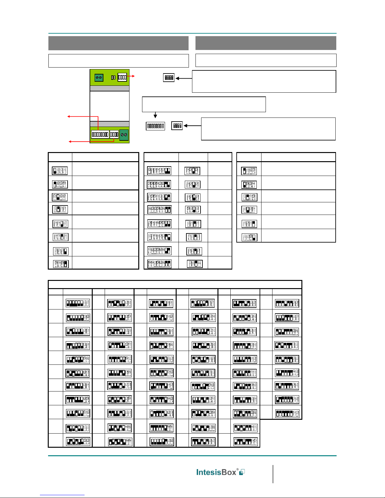
IMPORTANTE: Es necesario resetear el e quipo (quitar tensión) tras modificar
la configuración de los micro interruptores para que ésta se aplique.
IMPORTANT: It is required to reboot or power cycle the interface every time
the DIP switch configuration changes.
SW1-P1..4
Descripción
Description
SW3-P7..8
SW4-P3
Descripción
Description
SW4-P1..2-4
Descripción
Description
Esclavo .- Un Control Remoto Daikin BRC debe ser
presente en el bus P1 P2, configurado como Master
Slave – A Daikin BRC Controller must be present in the P1
P2 bus, configured as Master (Default value).
2400bps
Los valores de temperatura en los registros Modbus se
representan en decigrados (x10)
Temperature values in Modbus register are represented in
decidegrees (x10)
Maestro – No es necesario un Control Daikin BRC en el
bus P1 P2. Si existe, debe ser configurado como Esclavo.
Master - No need of a Daikin BRC Controller in the P1 P2
bus. If it exists, must be configured as Slave.
4800bps
Los valores de temperatura en los registros Modbus se
representan en grados (x1) (Valor por defecto).
Temperature values in Modbus register are represented in degrees
(x1) (Default value).
Maestro del Modo de Operación (Solo para VRV)
Master of Operation Mode (For VRV only)
9600bps
(Valor por defecto
default value)
Los valores de temperatura en los registros Modbus se
representan en grados Fahrenheit
Temperature values in Modbus register are represented in
Fahrenheit degrees
Esclavo de Modo de Operación (Solo para VRV)
(Valor por defecto)
Slave of Operating Mode (For VRV only) (Default value)
19200bps
Los valores de temperatura en los registros Modbus se
representan en grados Celsius (Valor por defecto)
Temperature values in Modbus register are r epresented in Celsius
degrees (Default value)
Reservado (Valor por defecto)
Not used (Default value)
38400bps
Resistencia interna de 120Ω conectada al bus EIA-485
Internal termination resistor of 120Ω connect ed to EIA-485 bus
Reservado
Not used
57600bps
Bus EIA-485 sin resistencia de terminación (V alor por defecto).
EIA-485 bus without termination resistor (Default value).
Muestra la temperatura ambiente proporcionada por la
Unidad Interior de Daikin (Valor por defecto)
Daikin Indoor Unit ambient temperature reading
(Default value)
76800bps
Muestra la temperatura ambiente proporcionada por el
Control Remoto de Daikin
Daikin Remote Controller ambient temperature reading
115200bps
Dirección de esclavo Modbus - Modbus Slave address
Direcc
Add
SW3-P1..6
Direcc
Add
SW3-P1..6
Direcc
Add
SW3-P1..6
Direcc
Add
SW3-P1..6
Direcc
Add
SW3-P1..6
Direcc
Add
SW3-P1..6
0
11
22
33
44
55
1
12
23
34
45
56
2
13
24
35
46
57
3
14
25
36
47
58
4
15
26
37
48
59
5
16
27
38
49
60
6
17
28
39
50
61
7
18
29
40
51
62
8
19
30
41
52
63
9
20
31
42
53
10
21
32
43
54
Configuración del número de esclavo Modbus y baudios.
Configuration of Modbus Slave number and baud rate.
Configuración de los baudios, magnitud temperatura (x1/x10), unidades de
temperatura (ºC/ºF) y resistencia de terminación de EIA-485.
Configuration of baud rate, temperature magnitude (x1/x10), temperature
units (Cº/Fº) and termination resistor for EIA-485.
IntesisBox®
DK-RC-MBS-1
EIA485
A+ B-
P1 P2
AC Unit
SW3
SW4
SW1
1 2 3 4
SW1
1 2 3 4
SW4
1 2 3 4 5 6 7 8
SW3
ON SAB
ON SAB
ON SAB
ON SAB
ON SAB
ON SAB
ON SAB
ON SAB
ON SAB
Configuración por micro interruptores
Configuration through DIP switches
ON SAB
ON SAB
ON SAB
ON SAB
ON SAB
ON SAB
ON SAB
ON SAB
ON SAB
ON SAB
ON SAB
ON SAB
ON SAB
ON SAB
ON SAB
ON SAB
ON SAB
ON SAB
ON SAB
ON SAB
ON SAB
ON SAB
ON SAB
ON SAB
ON SAB
ON SAB
ON SAB
ON SAB
ON SAB
ON SAB
ON SAB
ON SAB
ON SAB
ON SAB
ON SAB
ON SAB
ON SAB
ON SAB
ON SAB
ON SAB
ON SAB
ON SAB
ON SAB
ON SAB
ON SAB
ON SAB
ON SAB
ON SAB
ON SAB
ON SAB
ON SAB
ON SAB
ON SAB
ON SAB
ON SAB
ON SAB
ON SAB
ON SAB
Configuración Maestro/Esclavo, Esclavo del Modo de Operación, Modo de la lectura
de temperatura ambiente
Master/Slave, Master/Slave of Operating Mode, Ambient temperature reading
mode
ON
ON
ON
ON
ON
ON
ON
ON
ON
ON
ON
ON
ON
ON
ON
ON
ON
ON
ON
ON
ON
ON
ON
ON
ON
ON
ON
ON
ON
ON
 Loading...