

Page 1

IntesisBox
®
DK-RC-KNX-1i v2.0
User's Manual
Issue Date: 25/02/2016
r1.0 eng
Page 2

IntesisBox® KNX - Daikin A.C. (SKY & VRV line)
User's manual r1.0 eng
© Intesis Software S.L. - All rights reserved
This information is subject to change without notice
IntesisBox® is a registered trademark of Intesis Software SL
URL
Email
tel
http://www.intesis.com
info@intesis.com
+34 938047134
2 / 66
© Intesis Software S.L. 2016 All Rights Reserved.
Information in this document is subject to change without notice. The software described in
this document is furnished under a license agreement or nondisclosure agreement. The
software may be used only in accordance with the terms of those agreements. No part of this
publication may be reproduced, stored in a retrieval system or transmitted in any form or any
means electronic or mechanical, including photocopying and recording for any purpose other
than the purchaser’s personal use without the written permission of Intesis Software S.L.
Intesis Software S.L.
Milà I Fontanals, 1 bis
08700 Igualada
Spain
TRADEMARKS
All trademarks and tradenames used in this document are acknowledged to be the copyright of their respective holders.
Page 3

IntesisBox® KNX - Daikin A.C. (SKY & VRV line)
User's manual r1.0 eng
© Intesis Software S.L. - All rights reserved
This information is subject to change without notice
IntesisBox® is a registered trademark of Intesis Software SL
URL
Email
tel
http://www.intesis.com
info@intesis.com
+34 938047134
3 / 66
Gateway for integration of Daikin air conditioners
into KNX TP-1 (EIB) control systems.
Compatible with VRV and SKY line air conditioners
commercialized by Daikin.
Application’s Program Version: 2.0
Order Code: DK-RC-KNX-1i
Page 4

IntesisBox® KNX - Daikin A.C. (SKY & VRV line)
User's manual r1.0 eng
© Intesis Software S.L. - All rights reserved
This information is subject to change without notice
IntesisBox® is a registered trademark of Intesis Software SL
URL
Email
tel
http://www.intesis.com
info@intesis.com
+34 938047134
4 / 66
INDEX
1. Presentation .................................................................................................... 6
2. Connection ...................................................................................................... 7
2.1 DK-RC-KNX-1i without DAIKIN Remote Controller ............................................. 7
2.2 DK-RC-KNX-1i with DAIKIN Remote Controller .................................................. 7
3. Configuration and setup .................................................................................... 9
4. ETS Parameters ............................................................................................. 10
4.1 General dialog ............................................................................................ 11
4.1.1 DK-RC-KNX-1i is master in P1/P2 bus ...................................................... 11
4.1.2 Send READs for Control_ objects on bus recovery ..................................... 12
4.1.3 Scene to load on bus recovery / startup ................................................... 12
4.1.4 Disallow control from remote controller .................................................... 12
4.1.5 Enable func “Control_ Lock Control Obj” ................................................... 13
4.1.6 Enable func “Operating Hours Counter” .................................................... 13
4.1.7 Enable object “Error Code [2byte]” .......................................................... 14
4.1.8 Enable object “Error Text Code [14byte]” ................................................. 14
4.2 Mode Configuration dialog ............................................................................ 14
4.2.1 When mode is AUTO Status_ objs report actual operating status ................. 15
4.2.2 Enable use of Heat / Cool bit-type obj ...................................................... 15
4.2.3 Enable PID-Compat. Scaling Mode Objects ............................................... 16
4.2.4 Enable use of + / - object for Mode ......................................................... 16
4.2.5 Enable use of bit-type Mode objects (for control) ...................................... 17
4.2.6 Enable use of bit-type Mode objects (for status)........................................ 17
4.2.7 Enable use of Text object for Mode .......................................................... 18
4.2.8 Enable use of Legacy_ object for Mode .................................................... 18
4.3 Special Modes Configuration dialog ................................................................ 18
4.3.1 Enable use of POWER mode .................................................................... 19
4.3.2 Enable use of ECONOMY mode ................................................................ 20
4.3.3 Enable use of ADDITIONAL HEATING mode .............................................. 21
4.3.4 Enable use of ADDITIONAL COOLING mode .............................................. 21
4.4 Fan Speed Configuration dialog ..................................................................... 23
4.4.1 Available fan speeds in Indoor Unit .......................................................... 23
4.4.2 DPT object type for fanspeed .................................................................. 23
4.4.3 Enable use of +/- object for Fan Speed .................................................... 25
4.4.4 Enable use of bit-type Fan Speed objects (for Control) ............................... 26
4.4.5 Enable use of bit-type Fan Speed objects (for Status) ................................ 26
4.4.6 Enable use of Text object for Fan Speed ................................................... 27
4.4.7 Enable use of Legacy_ obj for Fan Speed ................................................. 27
4.5 Vane Up-Down Configuration dialog ............................................................... 28
4.5.1 Indoor unit has Up-Down Vanes .............................................................. 28
4.5.2 Enable “Control_ Vane U-D Swing” .......................................................... 28
4.5.3 DPT object type for Vane Up-Down .......................................................... 29
4.5.4 Enable use of +/- obj for Vane Up-Down .................................................. 30
4.5.5 Enable use of bit-type Vane U-D objects (for Control) ................................ 31
4.5.6 Enable use of bit-type Vane U-D objects (for Status) ................................. 31
4.5.7 Enable use of Text object for Vane U-D .................................................... 32
4.5.8 Enable use of Legacy_ obj for Vane U-D ................................................... 32
4.6 Temperature Configuration dialog.................................................................. 33
4.6.1 Periodic sending of “Status_ AC Setp” ...................................................... 33
4.6.2 Transmission of “Status_ AC Ret Temp” ................................................... 34
4.6.3 Enable use of +/- obj for Setp Temp ........................................................ 34
4.6.4 Enable limits on Control_ Setpoint obj ..................................................... 35
4.6.5 Ambient temp. ref. is provided from KNX ................................................. 35
4.7 Scene Configuration dialog ........................................................................... 37
Page 5

IntesisBox® KNX - Daikin A.C. (SKY & VRV line)
User's manual r1.0 eng
© Intesis Software S.L. - All rights reserved
This information is subject to change without notice
IntesisBox® is a registered trademark of Intesis Software SL
URL
Email
tel
http://www.intesis.com
info@intesis.com
+34 938047134
5 / 66
4.7.1 Enable use of scenes ............................................................................. 37
4.7.2 Scenes can be stored from KNX bus ........................................................ 38
4.7.3 Enable use of bit objects for scene execution ............................................ 39
4.7.4 Scene “x” preset ................................................................................... 39
4.8 Switch-Off Timeouts Configuration dialog ....................................................... 41
4.8.1 Enable use of Open Window / Switch off timeout function .......................... 41
4.8.2 Enable use of Occupancy function ........................................................... 42
4.8.3 Enable use of SLEEP timeout .................................................................. 45
4.9 Binary Input “x” Configuration dialog ............................................................. 46
4.9.1 Enable use of Input “x” .......................................................................... 46
4.9.2 Contact type ......................................................................................... 46
4.9.3 Debounce time ..................................................................................... 46
4.9.4 Disabling function.................................................................................. 47
4.9.5 Function ............................................................................................... 47
5. Specifications ................................................................................................. 55
6. AC Unit Types compatibility. ............................................................................ 56
7. Error Codes ................................................................................................... 57
Appendix A – Communication Objects Table ................................................................ 60
Page 6

IntesisBox® KNX - Daikin A.C. (SKY & VRV line)
User's manual r1.0 eng
© Intesis Software S.L. - All rights reserved
This information is subject to change without notice
IntesisBox® is a registered trademark of Intesis Software SL
URL
Email
tel
http://www.intesis.com
info@intesis.com
+34 938047134
6 / 66
1. Presentation
DK-RC-KNX-1i allows a complete and natural integration of DAIKIN air
conditioners with KNX control systems.
Compatible with all SKY Air and VRV models commercialized by DAIKIN.
Main features:
Reduced dimensions, quick installation.
Direct connection to P1/P2 bus, the bus that connects the AC indoor unit and the wired
remote controller.
Multiple objects for control and status (bit, byte, characters…) with KNX standard
datapoint types.
Status objects for every control available.
Special Modes available (Power, Economy, Additional Heating and Additional Cooling).
Timeout for Open Window and Occupancy. Sleep function also available.
Control of the AC unit based in the ambient temperature read by the own AC unit, or in
the ambient temperature read by any KNX thermostat.
Total Control and Monitoring of the AC unit from KNX, including monitoring of AC unit’s
state of internal variables, running hours counter (for filter maintenance control), and
error indication and error code.
AC unit can be controlled simultaneously by the remote controller of the AC unit and by
KNX.
Up to 5 scenes can be saved and executed from KNX, fixing the desired combination of
Operation Mode, Set Temperature, Fan Speed, Vane Position and Remote Controller
Lock in any moment by using a simple switching.
Four potential-free binary inputs provide the possibility to integrate many types of
external devices. Also configurable from ETS, they can be used for switching, dimming,
shutter/blind control, and more
Page 7
IntesisBox® KNX - Daikin A.C. (SKY & VRV line)
User's manual r1.0 eng
© Intesis Software S.L. - All rights reserved
This information is subject to change without notice
IntesisBox® is a registered trademark of Intesis Software SL
URL
Email
tel
http://www.intesis.com
info@intesis.com
+34 938047134
7 / 66
2. Connection
Connection of the DK-RC-KNX-1i to the AC indoor unit
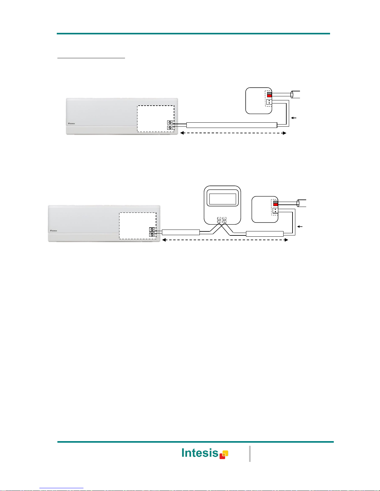
2.1 DK-RC-KNX-1i without DAIKIN Remote Controller
The DK-RC-KNX-1i can be connected directly to the P1/P2 bus of the indoor unit (no Daikin
remote controller -RC from now on- also connected in the P1 P2 bus). If this is the case, DKRC-KNX-1i must be configured as master (using the ETS software), see connection diagram
below.
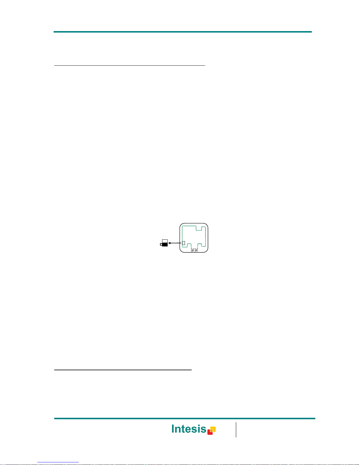
2.2 DK-RC-KNX-1i with DAIKIN Remote Controller
If a Daikin remote controller (RC) is present and connected to the P1/P2 bus, there are two
configuration options:
If we want to use the RC as master, its PCB switch must be set at “M” position and the
DK-RC-KNX-1i must be configured as slave.
If we want to use the RC as slave, its PCB switch must be set at “S” position and the
DK-RC-KNX-1i must be configured as master.
Check compatible Daikin remote controllers in the link provided in section 6.
Figure 2.1 Daikin RC PCB backside, MAIN/SUB switch
Special mention must be made with the use of Daikin’s IR wireless remote controllers, in this
case Daikin’s IR must be slave and the DK-RC-KNX-1i must be master, otherwise not all the
features will be available from KNX.
Disconnect mains power from the AC unit and use a 2 wire cable with a diameter of 0.75mm2
to 1.25mm2 for the connection of DK-RC-KNX-1i, Daikin’s remote controller and its
corresponding indoor unit. Screw the suitably peeled cable ends in the corresponding P1/P2
terminals of each device, as summarized in the Figure 2.2.
Maximum P1/P2 bus length is 500 meter. DAIKIN RC and DK-RC-KNX-1i are polarity
insensitive.
Connection of the DK-RC-KNX-1i to the KNX bus:
Disconnect power of the KNX bus. Connect the DK-RC-KNX-1i to the KNX TP-1 (EIB) bus using
the KNX standard connector (red/grey) of the DK-RC-KNX-1i, respect polarity.
Reconnect power of the KNX bus, and mains power of the AC unit.
S
M
Page 8
IntesisBox® KNX - Daikin A.C. (SKY & VRV line)
User's manual r1.0 eng
© Intesis Software S.L. - All rights reserved
This information is subject to change without notice
IntesisBox® is a registered trademark of Intesis Software SL
URL
Email
tel
http://www.intesis.com
info@intesis.com
+34 938047134
8 / 66
Connections diagrams:
DK-RC-KNX-1i without DAIKIN RC
DK-RC-KNX-1i with DAIKIN RC
Figure 2.2 Connections diagrams
Max. 500 m
P1
P2
Connection to P1 P2
bus. Two wires cable.
KNX TP-1
(EIB) bus
P1 P2
DAIKIN
AC Indoor Unit
Remote Control
AC Unit
P2
P1
DK-RC-KNX-1
IntesisBox ®
Internal
electronic
control board
P2
P1
Connection to P1 P2
bus. Two wires cable.
KNX TP-1
(EIB) bus
AC Indoor Unit
Max. 500 m
AC Unit
P1
P2
DK-RC-KNX-1
IntesisBox ®
Internal
electronic
control board
Page 9

IntesisBox® KNX - Daikin A.C. (SKY & VRV line)
User's manual r1.0 eng
© Intesis Software S.L. - All rights reserved
This information is subject to change without notice
IntesisBox® is a registered trademark of Intesis Software SL
URL
Email
tel
http://www.intesis.com
info@intesis.com
+34 938047134
9 / 66
3. Configuration and setup
This is a fully compatible KNX device which must be configured and setup using standard KNX
tool ETS.
ETS database for this device can be downloaded from:
http://www.intesis.com/down/eib/DK-RC-KNX-1i.zip
Please consult the README.txt file, located inside the downloaded zip file, to find instructions
on how to install the database.
IMPORTANT: Do not forget to select the correct settings of AC indoor unit being connected to
the DK-RC-KNX-1i (Fan speed and Vane), this is in "Parameters" of the device in ETS.
Page 10
IntesisBox® KNX - Daikin A.C. (SKY & VRV line)
User's manual r1.0 eng
© Intesis Software S.L. - All rights reserved
This information is subject to change without notice
IntesisBox® is a registered trademark of Intesis Software SL
URL
Email
tel
http://www.intesis.com
info@intesis.com
+34 938047134
10 / 66
4. ETS Parameters
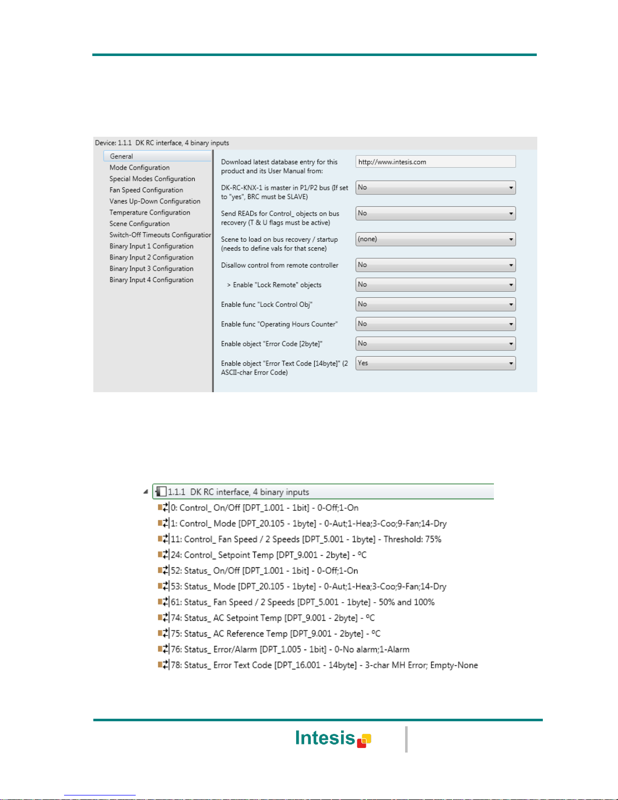
When imported to the ETS software for the first time, the gateway shows the following default
parameter configuration:
Figure 4.1 Default parameter configuration
With this configuration it’s possible to send On/Off (Control_ On/Off), change the AC Mode
(Control_ Mode), the Fan Speed (Control_ Fan Speed) and also the Setpoint Temperature
(Control_ Setpoint Temperature). The Status_ objects, for the mentioned Control_ objects,
are also available to use if needed. Also objects Status_ AC Reference Temp, Status_
Error/Alarm and Status_Error Text Code are shown.
Figure 4.2 Default communication objects
Page 11
IntesisBox® KNX - Daikin A.C. (SKY & VRV line)
User's manual r1.0 eng
© Intesis Software S.L. - All rights reserved
This information is subject to change without notice
IntesisBox® is a registered trademark of Intesis Software SL
URL
Email
tel
http://www.intesis.com
info@intesis.com
+34 938047134
11 / 66
4.1 General dialog
Inside this parameter’s dialog it is possible to activate or change the parameters shown in the
Figure 4.1.
The first field shows the URL where to download the database (or pr3) and the user manual
for the product.
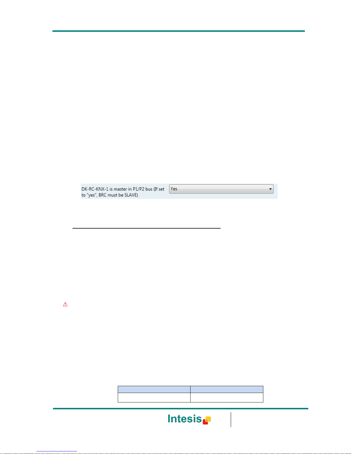
4.1.1 DK-RC-KNX-1i is master in P1/P2 bus
This parameter changes the gateway’s behavior, being able to program it as master or slave
in P1 P2 bus.
o If set to “no”, the gateway will work as a slave and it will be necessary to have a BRC
remote controller configured as a master.
o If set to “yes” the gateway will be master of the bus. It is not necessary to have any BRC
remote controller in this case but, if there are, they must be configured as slaves. The
next parameter is also shown when selecting DK-RC-KNX-1i as master in P1 P2 bus:
Figure 4.3 Parameter detail
If VRV system, indoor unit is slave of Operating Mode:
VRV indoor units can be configured as master or slave of Operating Mode.
If configured as slave = “yes”, the unit will take the operating mode of the master
indoor unit in the system (i.e. if master unit is in Heat mode, slaves will be also in
Heat mode).
If configured as slave = “no”, it means is the master unit, then the unit will take the
operating mode selected through the BRC or DK-RC-KNX-1i, and the other slave indoor
units will adopt this operating mode.
Important: Only ONE indoor unit can be configured as master of operating mode. If
more than one indoor unit is configured as master, the system will not work properly.
There are some compatible Operation Modes that slave indoor units can use while the
master indoor unit is operating in another one:
MASTER INDOOR UNIT
SLAVE INDOOR UNIT(s)
Heat
Heat, Fan
Page 12
IntesisBox® KNX - Daikin A.C. (SKY & VRV line)
User's manual r1.0 eng
© Intesis Software S.L. - All rights reserved
This information is subject to change without notice
IntesisBox® is a registered trademark of Intesis Software SL
URL
Email
tel
http://www.intesis.com
info@intesis.com
+34 938047134
12 / 66
Cool
Cool, Dry, Fan
Dry
Dry, Cool, Fan
Fan
Fan
Table 4.1 Operating Mode compatibility
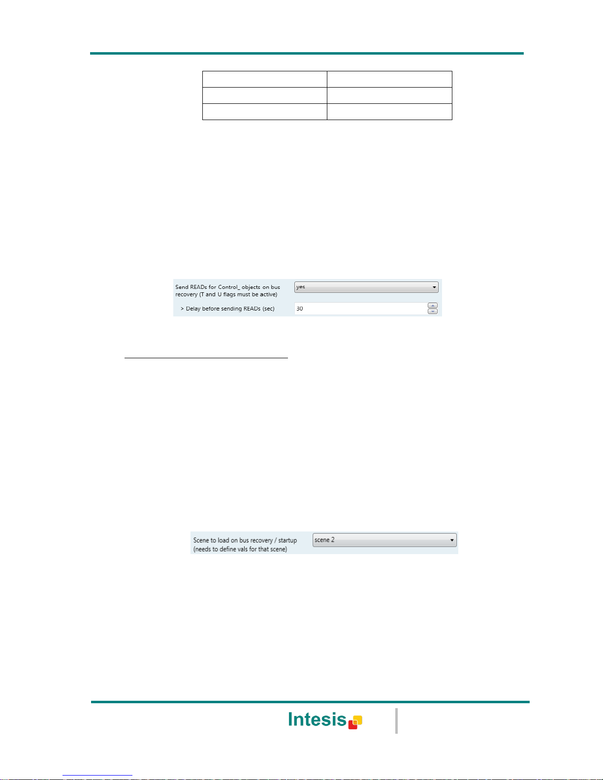
4.1.2 Send READs for Control_ objects on bus recovery
When this parameter is enabled, DK-RC-KNX-1i will send READ telegrams for the group
addresses associated on its Control_ objects on bus recovery or application reset/start-up.
o If set to “no” the gateway will not perform any action.
o If set to “yes” all Control_ objects with both Transmit (T) and Update (U) flags enabled
will send READs and their values will be updated with the response when received.
Figure 4.4 Parameter detail
Delay before sending READs (sec):
With this parameter, a delay can be configured between 0 and 30 seconds for the
READs sent by the Control_ objects. This is to give time enough to other KNX devices
on the bus to start-up before sending the READs.
4.1.3 Scene to load on bus recovery / startup
This parameter executes a selected scene on bus recovery or startup, only if the selected
scene has an enabled preset or values previously saved from KNX bus (see Scene
Configuration dialog).
If the gateway is disconnected from the indoor unit (P1 & P2 bus not connected) the scene
will not be applied, even when connecting to the indoor unit again.
Figure 4.5 Parameter detail
4.1.4 Disallow control from remote controller
This parameter allows:
1- Having the remote controller always locked, or
2- Decide through a new communication object if the RC is locked or not.
o If set to “yes” all the actions performed through the remote controller will be disabled.
Page 13
IntesisBox® KNX - Daikin A.C. (SKY & VRV line)
User's manual r1.0 eng
© Intesis Software S.L. - All rights reserved
This information is subject to change without notice
IntesisBox® is a registered trademark of Intesis Software SL
URL
Email
tel
http://www.intesis.com
info@intesis.com
+34 938047134
13 / 66
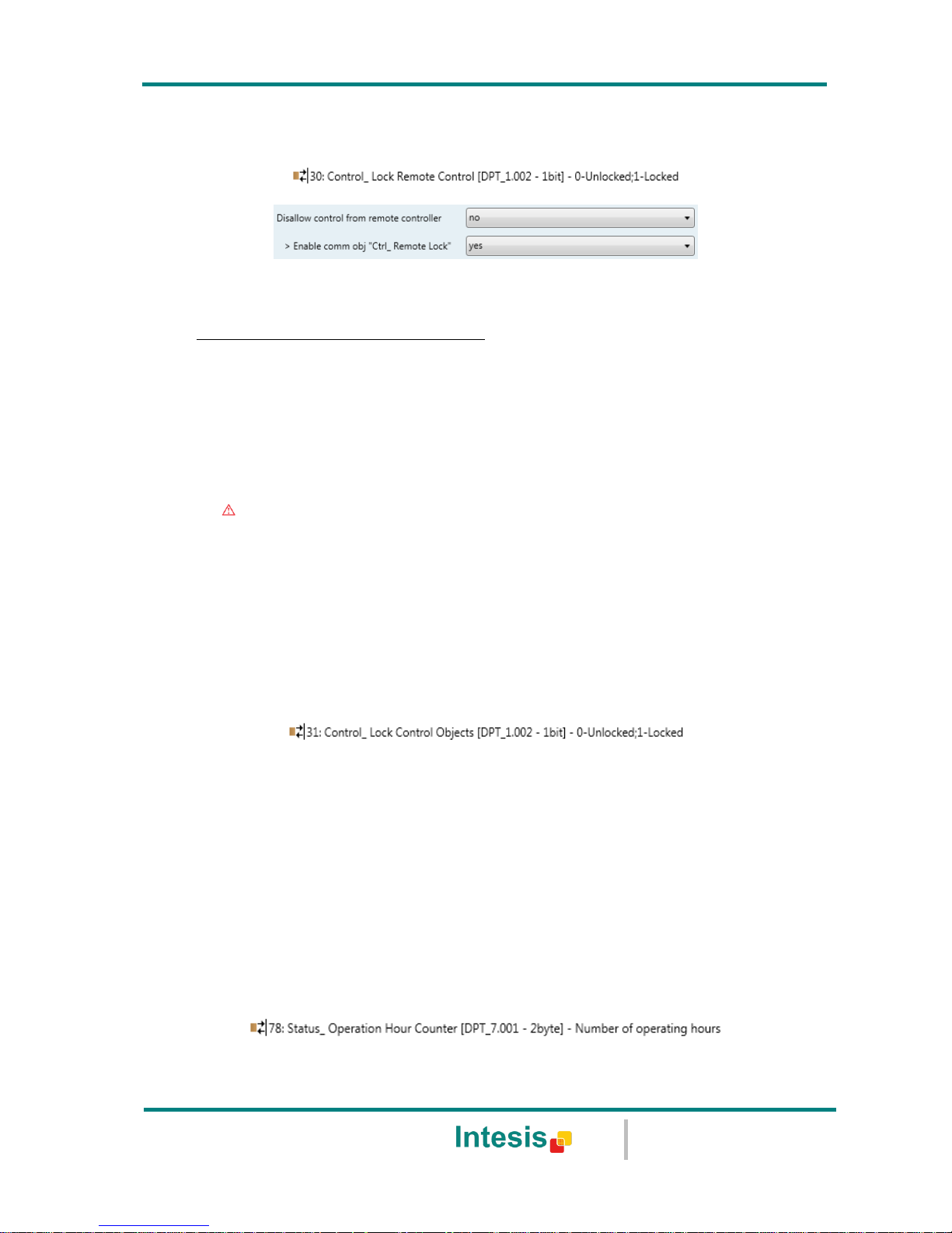
o If set to “no” the remote controller will work as usually. It also appears a new parameter
and the communication object Control_ Lock Remote Control.
Figure 4.6 Communication object and parameter detail
Enable comm obj “Ctrl_ Remote Lock”:
If set to “no” the object will not be shown.
If set to “yes” the Control_ Lock Remote Control object will appear.
When a “1” value is sent to this communication object, the remote controller
is locked. To be unlocked a “0” value must be sent. The gateway remembers
the last value received even if a KNX bus reset/failure happens.
Important: If an initial scene is enabled and it has as Value for Remote Lock
(unchanged) or unlocked, this would unlock the remote controller because the
initial scene has priority over the Control_ Lock Remote Control communication
object.
4.1.5 Enable func “Control_ Lock Control Obj”
This parameter shows/hide the Control_ Lock Control Obj communication object which,
depending on the sent value, locks or unlocks ALL the Control_ communication objects except
itself.
o If set to “no” the object will not be shown.
o If set to “yes” the Control_ Lock Control Objects object will appear.
When a “1” value is sent to this communication object, all the Control_ objects
will be locked. To unlock a “0” value must be sent, as the gateway remembers
the last value received even if a KNX bus reset/failure happens.
4.1.6 Enable func “Operating Hours Counter”
This parameter shows/hides the Status_ Operation Hour Counter communication object which
counts the number of operating hours for the DK-RC-KNX-1i.
o If set to “no” the object will not be shown.
Page 14

IntesisBox® KNX - Daikin A.C. (SKY & VRV line)
User's manual r1.0 eng
© Intesis Software S.L. - All rights reserved
This information is subject to change without notice
IntesisBox® is a registered trademark of Intesis Software SL
URL
Email
tel
http://www.intesis.com
info@intesis.com
+34 938047134
14 / 66
o If set to “yes” the Status_ Operation Hour Counter object will appear.
This object can be read and sends its status every time an hour is counted. The
gateway keeps that count in memory and the status is sent also after a KNX
bus reset/failure. Although this object is marked as a Status_ object it also can
be written to update the counter when needed. To reset the counter should be
written a “0” value.
Important: This object comes by default without the write (W) flag activated.
If is necessary to write on it, this flag must be activated.
Important: This object will also return its status, every time a value is written,
only if it’s different from the existing one.
Important: If the stored value is 0 hours, the gateway will not send the status
to KNX.
4.1.7 Enable object “Error Code [2byte]”
This parameter shows/hides the Status_ Error Code communication object which shows the
indoor unit errors, if occurred, in numeric format.
o If set to “no” the object will not be shown.
o If set to “yes” the Status_ Error Code [2byte] object will appear.
This object can be read and also sends the indoor unit error, if occurred, in
numeric format. If a “0” value is shown that means no error.
4.1.8 Enable object “Error Text Code [14byte]”
This parameter shows/hides the Status_ Error Text Code communication object which shows
the indoor unit errors, if occurred, in text format.
o If set to “no” the object will not be shown.
o If set to “yes” the Status_ Error Text Code object will appear.
This object can be read and also sends the indoor unit error, if occurred, in text
format. The errors shown have the same format as at the remote controller and
at the error list from the indoor unit manufacturer. If the object’s value is empty
that means no error.
4.2 Mode Configuration dialog
Page 15
IntesisBox® KNX - Daikin A.C. (SKY & VRV line)
User's manual r1.0 eng
© Intesis Software S.L. - All rights reserved
This information is subject to change without notice
IntesisBox® is a registered trademark of Intesis Software SL
URL
Email
tel
http://www.intesis.com
info@intesis.com
+34 938047134
15 / 66
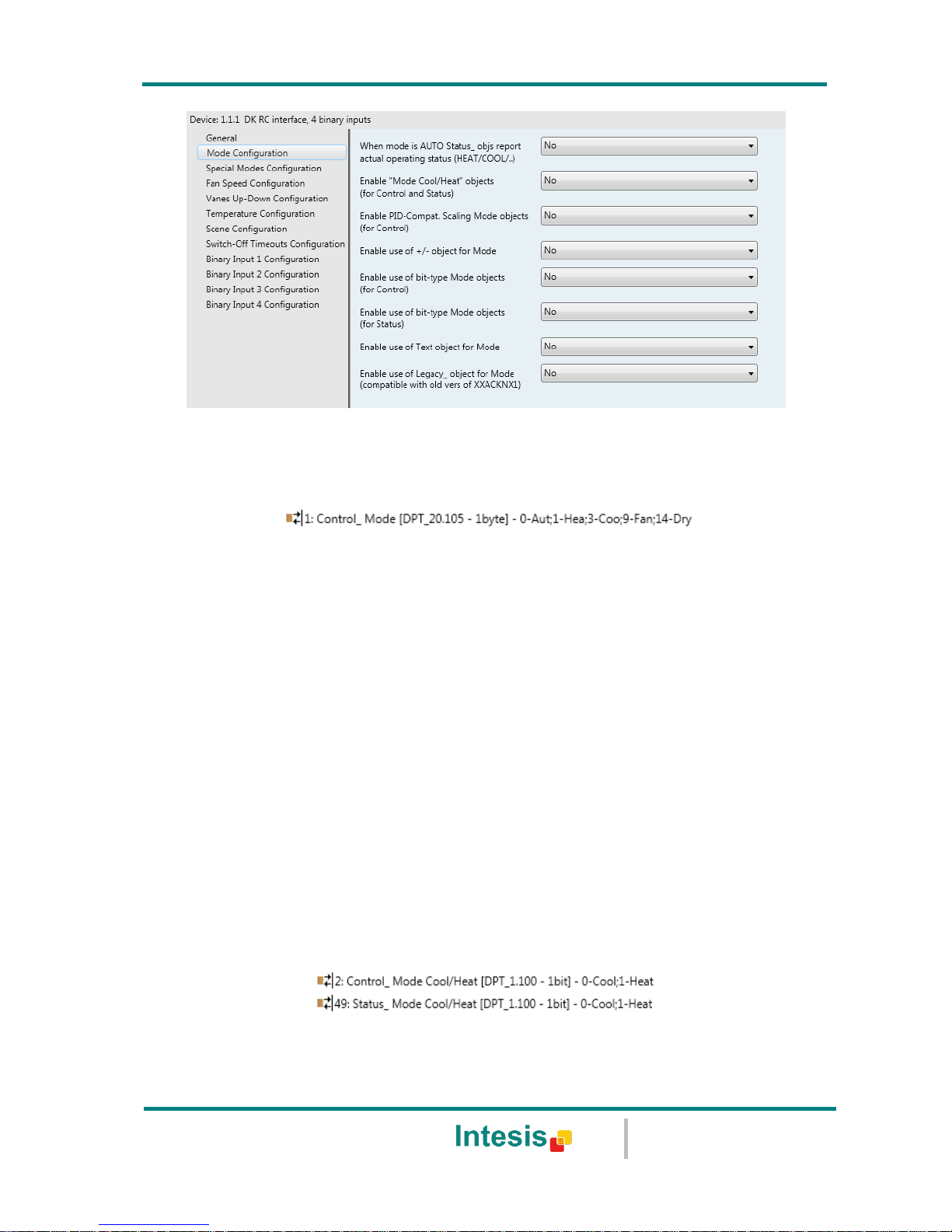
Figure 4.7 Default Mode Configuration dialog
All the parameters in this section are related with the different mode properties and
communication objects.
The byte-type communication object for Mode works with the DTP_20.105. Auto mode will be
enabled with a “0” value, Heat mode with a “1” value, Cool mode with a “3” value, Fan
mode with a “9” value and Dry mode with a “14” value.
4.2.1 When mode is AUTO Status_ objs report actual operating status
This parameter shows the real status of the indoor unit when Auto mode is enabled.
o If set to “no”, when the indoor unit is set to Auto mode, all the Status_ objects concerning
mode will only show Auto enabled.
o If set to “yes”, when the indoor unit is set to Auto mode, all the Status_ objects
concerning mode will show the real mode which the machine is working (Cool, Heat, Dry,
Fan). In case of the bitfield objects, also the Status_ Mode Auto will be shown enabled
with a “1” value.
4.2.2 Enable use of Heat / Cool bit-type obj
This parameter shows/hides the Control_ and Status_ Mode Cool/Heat communication
objects.
o If set to “no” the objects will not be shown.
o If set to “yes” the Control_ and Status_ Mode Cool/Heat objects will appear.
Page 16
IntesisBox® KNX - Daikin A.C. (SKY & VRV line)
User's manual r1.0 eng
© Intesis Software S.L. - All rights reserved
This information is subject to change without notice
IntesisBox® is a registered trademark of Intesis Software SL
URL
Email
tel
http://www.intesis.com
info@intesis.com
+34 938047134
16 / 66
When a “1” value is sent to the Control_ communication object, Heat mode
will be enabled in the indoor unit, and the Status_ object will return this value.
When a “0” value is sent to the Control_ communication object, Cool mode
will be enabled in the indoor unit, and the Status_ object will return this value.
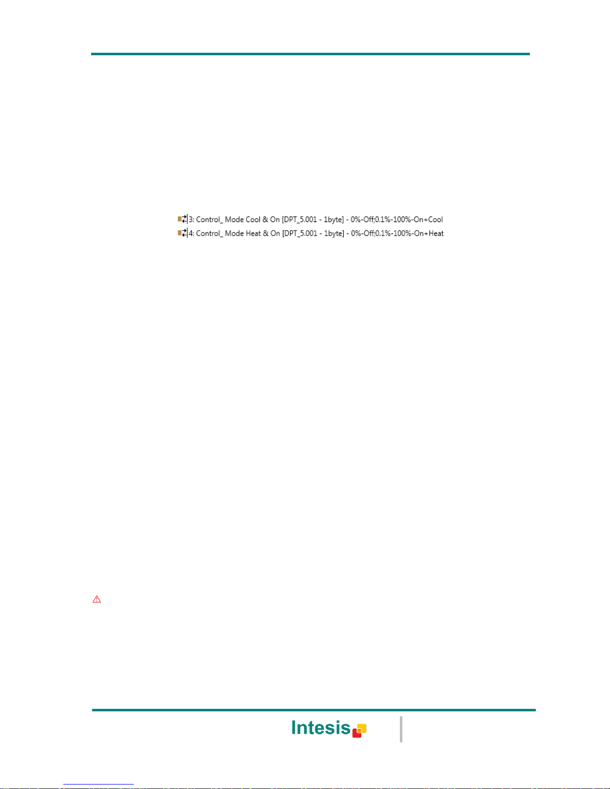
4.2.3 Enable PID-Compat. Scaling Mode Objects
This parameter shows/hides the Control_ Mode Cool & On and Control_ Mode Heat & On
communication objects.
o If set to “no” the objects will not be shown.
o If set to “yes” the Control_ Mode Cool & On and Control_ Mode Heat & On objects will
appear.
These objects provide compatibility with those KNX thermostats that control
the demand of heating or cooling by using scaling (percentage) objects. In
these thermostats, the percentage demand is meant to be applied on a fluid
valve of the heating / cooling system.
DK-RC-KNX-1i device does not provide individual control on the internal parts
of the indoor unit (as can be its compressor, refrigerant valves, etc). Rather, it
provides the same level of control as a (user) remote controller.
Objects “Control_ Mode Cool & On” and “Control_ Mode Heat & On” intend to
bring compatibility between thermostats oriented to the control of custom
heating / cooling systems and ready-made AC indoor units, by applying the
following logic:
Whenever a non-zero value (>0%) is received at “Control_ Mode Cool
& On”, indoor unit will switch On in COOL mode.
Whenever a non-zero value (>0%) is received at “Control_ Mode Heat
& On”, indoor unit will switch On in HEAT mode.
Lastest updated object will define the operating mode
Indoor unit will switch off only when both objects become zero (0%) –
or when an OFF is requested at object “0. On/Off [DPT_1.001 - 1bit]”
Important: These objects function is only to send On/Off and Cool/Heat to the indoor
unit. The PID (Inverter system) is calculated by the indoor unit itself. Please consider
introducing an appropriate PID configuration to the external KNX thermostat to not
interfere the indoor unit PID.
4.2.4 Enable use of + / - object for Mode
Page 17
IntesisBox® KNX - Daikin A.C. (SKY & VRV line)
User's manual r1.0 eng
© Intesis Software S.L. - All rights reserved
This information is subject to change without notice
IntesisBox® is a registered trademark of Intesis Software SL
URL
Email
tel
http://www.intesis.com
info@intesis.com
+34 938047134
17 / 66
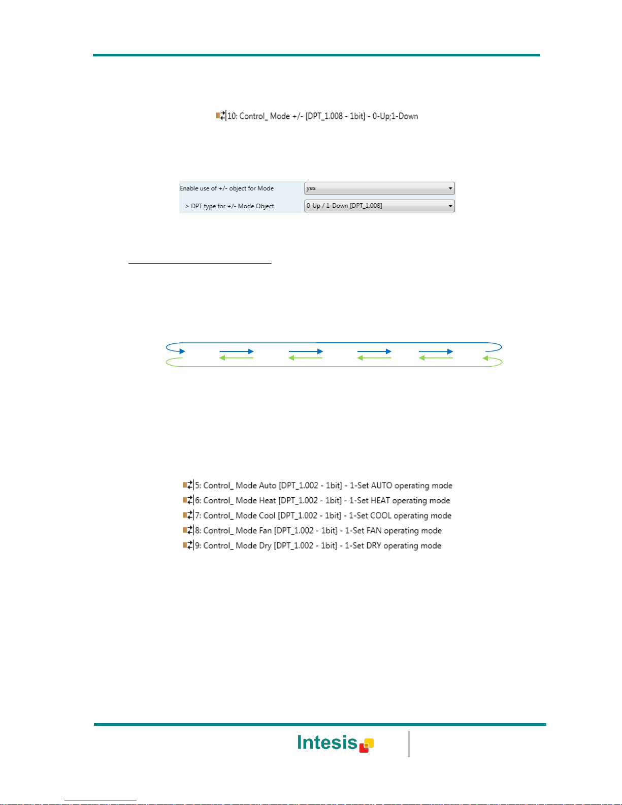
This parameter shows/hides the Control_ Mode +/- communication object which lets change
the indoor unit mode by using two different datapoint types.
o If set to “no” the object will not be shown.
o If set to “yes” the Control_ Mode +/- object and a new parameter will appear.
Figure 4.8 Parameter detail
DPT type for +/- Mode Object
This parameter lets choose between the datapoints 0-Up / 1-Down [DPT_1.008]
and 0-Decrease / 1-Increase [DPT_1.007] for the Control_ Mode +/- object.
The sequence followed when using this object is shown below:
4.2.5 Enable use of bit-type Mode objects (for control)
This parameter shows/hides the bit-type Control_ Mode objects.
o If set to “no” the objects will not be shown.
o If set to “yes” the Control_ Mode objects for Auto, Heat, Cool, Fan and Dry will appear.
To activate a mode by using these objects a “1” value has to be sent.
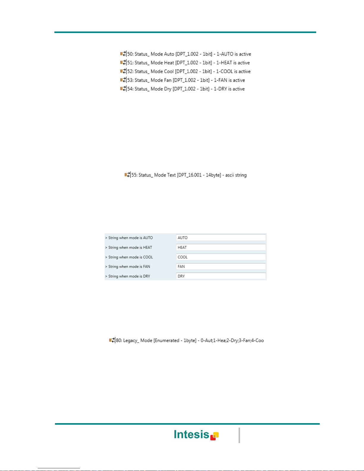
4.2.6 Enable use of bit-type Mode objects (for status)
This parameter shows/hides the bit-type Status_ Mode objects.
Up / Increase
Down / Decrease
DRY
AUTO
HEAT
COOL
FAN
Page 18
IntesisBox® KNX - Daikin A.C. (SKY & VRV line)
User's manual r1.0 eng
© Intesis Software S.L. - All rights reserved
This information is subject to change without notice
IntesisBox® is a registered trademark of Intesis Software SL
URL
Email
tel
http://www.intesis.com
info@intesis.com
+34 938047134
18 / 66
o If set to “no” the objects will not be shown.
o If set to “yes” the Status_ Mode objects for Auto, Heat, Cool, Fan and Dry will appear.
When enabled, a mode will return a “1” through its bit-type object.
4.2.7 Enable use of Text object for Mode
This parameter shows/hides the Status_ Mode Text communication object.
o If set to “no” the object will not be shown.
o If set to “yes” the Status_ Mode Text object will appear. Also, in the parameters, will be
shown five text fields, one for each mode, that will let modify the text string displayed by
the Status_ Mode Text when changing mode.
Figure 4.9 Parameter detail
4.2.8 Enable use of Legacy_ object for Mode
This parameter shows/hides the Legacy_ Mode communication object.
o If set to “no” the object will not be shown.
o If set to “yes” the Legacy_ Mode object will appear. This object lets change the indoor
unit mode but it uses a different data type. It is used to maintain compatibility with old
gateway models.
Auto mode will be enabled with a “0” value, Heat mode with a “1” value, Dry mode with
a “2” value, Fan mode with a “3” value and Cool mode with a “4” value
4.3 Special Modes Configuration dialog
Page 19
IntesisBox® KNX - Daikin A.C. (SKY & VRV line)
User's manual r1.0 eng
© Intesis Software S.L. - All rights reserved
This information is subject to change without notice
IntesisBox® is a registered trademark of Intesis Software SL
URL
Email
tel
http://www.intesis.com
info@intesis.com
+34 938047134
19 / 66
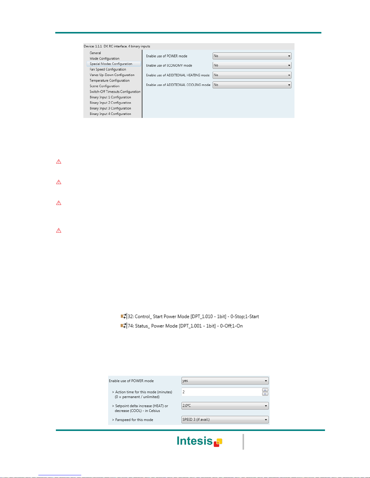
Figure 4.10 Default Special Modes Configuration dialog
The Special Modes can be parameterized through the ETS parameters dialog, and they can
be used to give extra functionality.
Important: When executing any of the Special Modes, the real state of the indoor unit
will NOT be shown in KNX.
Important: When the predefined time for the Special Mode is finished or a “0” value is
sent to stop it. The previous state will be recovered.
Important: If a value concerning On/Off, Mode, Fan Speed or Setpoint Temperature is
received from KNX while any Special Mode is running (“1”), the Special Mode will stop
and the previous state will be recovered. The value received will be also applied then.
Important: If a value concerning On/Off, Mode, Fan Speed or Setpoint Temperature is
modified through the remote controller, the Special Mode will stop WITHOUT recovering
the previous state. Then the real indoor unit state will be shown in KNX including the new
value received through the remote controller.
4.3.1 Enable use of POWER mode
This parameter shows/hides the Control_ Start Power Mode and Status_ Power Mode
communication objects. The Power Mode lets change the Setpoint Temperature and the Fan
Speed within a given period of time.
o If set to “no” the objects will not be shown.
o If set to “yes” the Control_ Start Power Mode and Status_ Power Mode objects and new
parameters will appear.
Page 20
IntesisBox® KNX - Daikin A.C. (SKY & VRV line)
User's manual r1.0 eng
© Intesis Software S.L. - All rights reserved
This information is subject to change without notice
IntesisBox® is a registered trademark of Intesis Software SL
URL
Email
tel
http://www.intesis.com
info@intesis.com
+34 938047134
20 / 66
Figure 4.11 Parameter detail
When a “1” value is sent to the Control_ communication object Power Mode
will be enabled, and the Status_ object will return this value.
When a “0” value is sent to the Control_ communication object, Power Mode
will be disabled, and the Status_ object will return this value.
Important: This mode will ONLY work if the indoor unit is both turned on and
in a Heat, Cool, Auto-Heat or Auto-Cool Mode.
Action time for this mode (minutes):
Duration of Power Mode, in minutes, once started.
Setpoint delta increase (HEAT) or decrease (COOL) – in Celsius:
Number of degrees Celsius that will increase in Heat Mode, or decrease in Cool Mode,
while in Power Mode.
Fan Speed for this mode:
Fan Speed that will be set in the unit while in Power Mode.
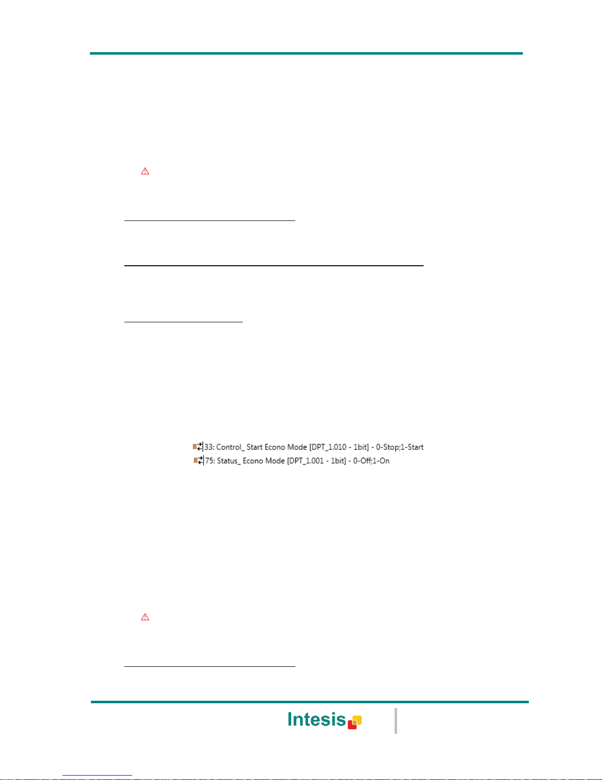
4.3.2 Enable use of ECONOMY mode
This parameter shows/hides the Control_ Start Econo Mode and Status_ Econo Mode
communication objects. The Econo Mode lets change the Setpoint Temperature and the Fan
Speed within a given period of time.
o If set to “no” the objects will not be shown.
o If set to “yes” the Control_ Start Econo Mode and Status_ Econo Mode objects and new
parameters will appear.
When a “1” value is sent to the Control_ communication object, EconoMode
will be enabled, and the Status_ object will return this value.
When a “0” value is sent to the Control_ communication object, EconoMode
will be disabled, and the Status_ object will return this value.
Important: This mode will ONLY work if the indoor unit is both turned on and
in a Heat, Cool, Auto-Heat or Auto-Cool Mode.
Action time for this mode (minutes):
Duration of EconoMode, in minutes, once started.
Page 21

IntesisBox® KNX - Daikin A.C. (SKY & VRV line)
User's manual r1.0 eng
© Intesis Software S.L. - All rights reserved
This information is subject to change without notice
IntesisBox® is a registered trademark of Intesis Software SL
URL
Email
tel
http://www.intesis.com
info@intesis.com
+34 938047134
21 / 66
Setpoint delta increase (HEAT) or decrease (COOL) – in Celsius:
Number of degrees Celsius that will increase in Heat Mode, or decrease in Cool Mode,
while in EconoMode.
Fan Speed for this mode:
Fan Speed that will be set in the unit while in EconoMode.
4.3.3 Enable use of ADDITIONAL HEATING mode
This parameter shows/hides the Control_ Start Additional Heat Mode and Status_ Additional
Heat Mode communication objects. The Additional Heating Mode lets change the Setpoint
Temperature and the Fan Speed within a given period of time.
o If set to “no” the objects will not be shown.
o If set to “yes” the Control_ Start Additional Heat Mode and Status_ Additional Heat Mode
objects and new parameters will appear.
When a “1” value is sent to the Control_ communication object, Additional
Heating Mode will be enabled, and the Status_ object will return this value.
When a “0” value is sent to the Control_ communication object, Additional
Heating Mode will be disabled, and the Status_ object will return this value.
Important: This mode will ALWAYS turn on the indoor unit in Heat mode.
Action time for this mode (minutes):
Duration of Additional Heating Mode, in minutes, once started.
Setpoint temp for this mode (ºC):
Setpoint temperature that will be applied while in Additional Heating Mode.
Fan Speed for this mode:
Fan Speed that will be set in the unit while in Additional Heating Mode.
4.3.4 Enable use of ADDITIONAL COOLING mode
This parameter shows/hides the Control_ Start Additional Cool Mode and Status_ Additional
Cool Mode communication objects. The Additional Heating Mode lets change the Setpoint
Temperature and the Fan Speed within a given period of time.
Page 22

IntesisBox® KNX - Daikin A.C. (SKY & VRV line)
User's manual r1.0 eng
© Intesis Software S.L. - All rights reserved
This information is subject to change without notice
IntesisBox® is a registered trademark of Intesis Software SL
URL
Email
tel
http://www.intesis.com
info@intesis.com
+34 938047134
22 / 66
o If set to “no” the objects will not be shown.
o If set to “yes” the Control_ Start Additional Cool Mode and Status_ Additional Cool Mode
objects and new parameters will appear.
When a “1” value is sent to the Control_ communication object, Additional
Cooling Mode will be enabled, and the Status_ object will return this value.
When a “0” value is sent to the Control_ communication object, Additional
Cooling Mode will be disabled, and the Status_ object will return this value.
Important: This mode will ALWAYS turn on the indoor unit in Cool mode.
Action time for this mode (minutes):
Duration of Additional Cooling Mode, in minutes, once started.
Setpoint temp for this mode (ºC):
Setpoint temperature that will be applied while in Additional Cooling Mode.
Fan Speed for this mode:
Fan Speed that will be set in the unit while in Additional Cooling Mode.
Page 23

IntesisBox® KNX - Daikin A.C. (SKY & VRV line)
User's manual r1.0 eng
© Intesis Software S.L. - All rights reserved
This information is subject to change without notice
IntesisBox® is a registered trademark of Intesis Software SL
URL
Email
tel
http://www.intesis.com
info@intesis.com
+34 938047134
23 / 66
4.4 Fan Speed Configuration dialog
Figure 4.12 Default Fan Speed Configuration dialog
All the parameters in this section are related with the Fan Speed properties and
communication objects.
4.4.1 Available fan speeds in Indoor Unit
This parameter lets you choose how many fan speeds are available in the indoor unit (2 or 3
speeds available).
Figure 4.13 Parameter detail
Changing the fan speeds will also change the fan speed byte-type object (and the bit-type
objects) erasing all the group addresses associated.
Important: Read the documentation of your indoor unit to check how many fan speeds
are available.
4.4.2 DPT object type for fanspeed
With this parameter is possible to change de DPT for the Control_ Fan Speed and Status_ Fan
Speed byte-type communication objects. Datapoints Scaling (DPT_5.001) and Enumerated
(DPT_5.010) can be selected.
o When “Enumerated [DPT 5.010]” is selected, Control_ Fan Speed and Status_ Fan
Speed communication objects for this DPT will appear. Also, depending on the number of
fan speeds selected, these objects will be different.
Page 24

IntesisBox® KNX - Daikin A.C. (SKY & VRV line)
User's manual r1.0 eng
© Intesis Software S.L. - All rights reserved
This information is subject to change without notice
IntesisBox® is a registered trademark of Intesis Software SL
URL
Email
tel
http://www.intesis.com
info@intesis.com
+34 938047134
24 / 66
If this DPT is selected with 2 fan speeds:
The first fan speed will be selected if a “1” is sent to the Control_ object. The second
fan speed will be selected sending a “2”.
The Status_ object will always return the value for the fan speed selected.
If this DPT is selected with 3 fan speeds:
The first fan speed will be selected if a “1” is sent to the Control_ object. The second
one will be selected sending a “2”, and the last one sending a “3”.
The Status_ object will always return the value for the fan speed selected.
Important: In both cases if a “0” value is sent to the Control_ object, the minimum
fan speed will be selected. If a value bigger than “2” (in case of 2 speeds) or bigger
than “3” (in case of 3 fan speeds) is sent to the Control_ object, then the maximum
fan speed will be selected.
o When “Scaling [DPT 5.001]” is selected, Control_ Fan Speed and Status_ Fan Speed
communication objects for this DPT will appear. Also, depending on the number of fan
speeds selected, these objects will be different.
If this DPT is selected with 2 fan speeds:
When a value between 0% and 74% is sent to the Control_ object the first fan speed will
be selected.
When a value between 75% and 100% is sent to the Control_ object, the second speed
will be selected.
The Status_ object will return a 50% for the first fan speed, and a 100% for the second
one.
Page 25

IntesisBox® KNX - Daikin A.C. (SKY & VRV line)
User's manual r1.0 eng
© Intesis Software S.L. - All rights reserved
This information is subject to change without notice
IntesisBox® is a registered trademark of Intesis Software SL
URL
Email
tel
http://www.intesis.com
info@intesis.com
+34 938047134
25 / 66
If this DPT is selected with 3 fan speeds:
When a value between 0% and 49% is sent to the Control_ object the first fan speed will
be selected.
When a value between 50% and 83% is sent to the Control_ object, the second speed
will be selected.
When a value between 84% and 100% is sent to the Control_ object, the third speed
will be selected.
The Status_ object will return a 33% when the first speed is selected, a 67% for the
second one and a 100% for the third one.
4.4.3 Enable use of +/- object for Fan Speed
This parameter shows/hides the Control_ Fan Speed +/- communication object which lets you
increase/decrease the indoor unit fan speed by using two different datapoint types.
o If set to “no” the object will not be shown.
o If set to “yes” the Control_ Fan Speed +/- object and a new parameter will appear.
Fan Speed 1
Fan Speed 3
100%
Status_
0%
83%
50%
Control_
Control_
Status_
33%
67%
Fan Speed 2
Control_
Status_
Fan Speed 1
Fan Speed 2
100%
Status_
0%
75%
50%
Control_
Control_
Status_
Page 26

IntesisBox® KNX - Daikin A.C. (SKY & VRV line)
User's manual r1.0 eng
© Intesis Software S.L. - All rights reserved
This information is subject to change without notice
IntesisBox® is a registered trademark of Intesis Software SL
URL
Email
tel
http://www.intesis.com
info@intesis.com
+34 938047134
26 / 66
Figure 4.14 Parameter detail
DPT type for +/- Fan Speed Object
This parameter lets choose between the datapoints 0-Up / 1-Down [DPT_1.008]
and 0-Decrease / 1-Increase [DPT_1.007] for the Control_ Fan Speed +/- object.
Roll-over Speed at upper/lower limit
This parameter lets choose if roll-over will be enabled (“yes”) or disabled (“no”) for
the Control_ Fan Speed +/- object.
4.4.4 Enable use of bit-type Fan Speed objects (for Control)
This parameter shows/hides the bit-type Control_ Fan Speed objects.
o If set to “no” the objects will not be shown.
o If set to “yes” the Control_ Fan Speed objects for Speed 1, Speed 2 and Speed 3 (if
available) will appear. To activate a Fan Speed by using these objects a “1” value has to
be sent.
4.4.5 Enable use of bit-type Fan Speed objects (for Status)
This parameter shows/hides the bit-type Status_ Fan Speed objects.
Up / Increase
Down / Decrease
Fan Speed 3
Fan Speed 1
Fan Speed 2
Only if Roll-over is enabled
Only if Roll-over is enabled
Page 27

IntesisBox® KNX - Daikin A.C. (SKY & VRV line)
User's manual r1.0 eng
© Intesis Software S.L. - All rights reserved
This information is subject to change without notice
IntesisBox® is a registered trademark of Intesis Software SL
URL
Email
tel
http://www.intesis.com
info@intesis.com
+34 938047134
27 / 66
o If set to “no” the objects will not be shown.
o If set to “yes” the Status_ Fan Speed objects for Speed 1, Speed 2 and Speed 3 (if
available) will appear. When a Fan Speed is enabled, a “1” value is returned through its
bit-type object.
4.4.6 Enable use of Text object for Fan Speed
This parameter shows/hides the Status_ Fan Speed Text communication object.
o If set to “no” the object will not be shown.
o If set to “yes” the Status_ Fan Speed Text object will appear. Also, in the parameters,
will be shown two (or three, depending on the number of fan speeds selected) text fields,
one for each Fan Speed, that will let modify the text string displayed by the Status_ Fan
Speed Text when changing a fan speed.
Figure 4.15 Parameter detail
4.4.7 Enable use of Legacy_ obj for Fan Speed
This parameter shows/hides the Legacy_ Fan Speed communication object.
o If set to “no” the object will not be shown.
o If set to “yes” the Legacy_ Fan Speed object will appear. This object lets change the
indoor unit Fan Speed but it uses a different data type. It is used to maintain compatibility
with old gateway models.
Page 28

IntesisBox® KNX - Daikin A.C. (SKY & VRV line)
User's manual r1.0 eng
© Intesis Software S.L. - All rights reserved
This information is subject to change without notice
IntesisBox® is a registered trademark of Intesis Software SL
URL
Email
tel
http://www.intesis.com
info@intesis.com
+34 938047134
28 / 66
4.5 Vane Up-Down Configuration dialog
Figure 4.16 Vane Up-Down Configuration dialog
All the parameters in this section are related with the Vane Up-Down properties and
communication objects.
4.5.1 Indoor unit has Up-Down Vanes
This parameter lets you choose if the unit has Up-Down Vanes available or not.
Figure 4.17 Parameter detail
o If set to “no” all the parameters and communication objects for the Up-Down Vanes will
not be shown.
o If set to “yes” all the parameters and communication objects (if enabled in the parameters
dialog) for the Up-Down Vanes will be shown.
Important: Read the documentation of your indoor unit to check if Up-Down Vanes are
available.
4.5.2 Enable “Control_ Vane U-D Swing”
This parameter shows/hides the Control_ Vane Up-Down Swing and Status_ Vane Up-Down
Swing communication object.
Page 29

IntesisBox® KNX - Daikin A.C. (SKY & VRV line)
User's manual r1.0 eng
© Intesis Software S.L. - All rights reserved
This information is subject to change without notice
IntesisBox® is a registered trademark of Intesis Software SL
URL
Email
tel
http://www.intesis.com
info@intesis.com
+34 938047134
29 / 66
o If set to “no” the object will not be shown.
o If set to “yes” the Control_ Vane Up-Down Swing and Status_ Vane Up-Down Swing
objects will appear.
When a “1” value is sent to the Control_ object, the indoor unit enables the
Swing function for the vanes. The Status_ object returns a “1” value.
When a “0” value is sent to the Control_ object, the Swing function for the
vanes stops and the indoor unit puts them to Position 1. The Status_ object
returns a “0” value.
Important: If a “0” value is sent to the Control_ object while the Swing
function is disabled, the value will be ignored and no change will be applied.
4.5.3 DPT object type for Vane Up-Down
With this parameter is possible to change de DPT for the Control_ Vane Up-Down and Status_
Vane Up-Down byte-type communication objects. Datapoints Scaling (DPT_5.001) and
Enumerated (DPT_5.010) can be selected.
o When “Enumerated [DPT 5.010]” is selected, Control_ Vane Up-Down and Status_
Vane Up-Down communication objects for this DPT will appear.
To choose a vane position, values from “1” to “5” can be sent to the Control_ object.
Each value will correspond to the position (i.e. Value “3” = Position 3).
The Status_ object will always return the value for the vane position selected.
Important: If a “0” value is sent to the Control_ object, the Position 1 will be selected.
If a value bigger than “5” is sent to the Control_ object, then the Position 5 will be
selected.
o When “Scaling [DPT 5.001]” is selected, Control_ Vane Up-Down and Status_ Vane Up-
Down communication objects for this DPT will appear.
When a value between 0% and 29% is sent to the Control_ object the first vane position
will be selected.
When a value between 30% and 49% is sent to the Control_ object, the second vane
position will be selected.
Page 30

IntesisBox® KNX - Daikin A.C. (SKY & VRV line)
User's manual r1.0 eng
© Intesis Software S.L. - All rights reserved
This information is subject to change without notice
IntesisBox® is a registered trademark of Intesis Software SL
URL
Email
tel
http://www.intesis.com
info@intesis.com
+34 938047134
30 / 66
When a value between 50% and 69% is sent to the Control_ object, the third vane
position will be selected.
When a value between 70% and 89% is sent to the Control_ object, the fourth vane
position will be selected.
When a value between 90% and 100% is sent to the Control_ object, the fifth vane
position will be selected.
The Status_ object will return a 20% for the first vane position, a 40% for the second
one, a 60% for the third one, an 80% for the fourth one and a 100% for the fifth and
last one.
4.5.4 Enable use of +/- obj for Vane Up-Down
This parameter shows/hides the Control_ Vane Up-Down +/- communication object which lets
you change the indoor unit vane position by using two different datapoint types.
o If set to “no” the object will not be shown.
o If set to “yes” the Control_ Vane Up-Down +/- object and a new parameter will appear.
Figure 4.18 Parameter detail
DPT type for +/- Vane Up-Down obj
This parameter lets choose between the datapoints 0-Up / 1-Down [DPT_1.008]
and 0-Decrease / 1-Increase [DPT_1.007] for the Control_ Vane Up-Down +/-
object.
Does +/- sequen. incl. vane SWING?
Pos. 1
Pos. 3
100%
Status_
0%
90%
50%
Control_
Control_
Status_
30%
70%
Pos. 2
Control_
Status_
Pos. 4
Pos. 5
Control_
Control_
20%
40%
60%
80%
Status_
Status_
Page 31

IntesisBox® KNX - Daikin A.C. (SKY & VRV line)
User's manual r1.0 eng
© Intesis Software S.L. - All rights reserved
This information is subject to change without notice
IntesisBox® is a registered trademark of Intesis Software SL
URL
Email
tel
http://www.intesis.com
info@intesis.com
+34 938047134
31 / 66
This parameter lets you choose if SWING function is included (“yes”) or not (“no”)
in the sequence when using Control_ Vane Up-Down +/- object as shown in the
discontinuous segment at the picture below.
Rollover Vane at upper/lower limit
This parameter lets choose if roll-over will be enabled (“yes”) or disabled (“no”) for
the Vane Up-Down +/- object.
4.5.5 Enable use of bit-type Vane U-D objects (for Control)
This parameter shows/hides the bit-type Control_ Vane Up-Down objects.
o If set to “no” the objects will not be shown.
o If set to “yes” the Control_ Vane Up-Down objects for each Position (1 to 5) will appear.
To activate a Vane Position by using these objects, a “1” value has to be sent.
4.5.6 Enable use of bit-type Vane U-D objects (for Status)
This parameter shows/hides the bit-type Status_ Vane Up-Down objects.
o If set to “no” the objects will not be shown.
o If set to “yes” the Status_ Vane Up-Down objects for each Position (1 to 5) will appear.
When a Vane Position is enabled, a “1” value is returned through its bit-type object.
Up / Increase
Down / Decrease
Pos. 3
Pos. 1
Pos. 2
Only if Roll-over is enabled
Only if Roll-over is enabled
Pos. 5
Pos. 4
SWING
Page 32

IntesisBox® KNX - Daikin A.C. (SKY & VRV line)
User's manual r1.0 eng
© Intesis Software S.L. - All rights reserved
This information is subject to change without notice
IntesisBox® is a registered trademark of Intesis Software SL
URL
Email
tel
http://www.intesis.com
info@intesis.com
+34 938047134
32 / 66
4.5.7 Enable use of Text object for Vane U-D
This parameter shows/hides the Status_ Vane Up-Down Text communication object.
o If set to “no” the object will not be shown.
o If set to “yes” the Status_ Vane Up-Down Text object will appear. Also, in the parameters
will be shown six text fields, five for the Vane Position and one for the Swing function, that
will let modify the text string displayed by the Status_ Vane Up-Down Text when changing
a vane position.
Figure 4.19 Parameter detail
4.5.8 Enable use of Legacy_ obj for Vane U-D
This parameter shows/hides the Legacy_ Vane Up-Down communication object.
o If set to “no” the object will not be shown.
o If set to “yes” the Legacy_ Vane Up-Down object will appear. This object lets change the
indoor unit Vane Position but it uses a different data type. It is used to maintain
compatibility with old gateway models.
Page 33

IntesisBox® KNX - Daikin A.C. (SKY & VRV line)
User's manual r1.0 eng
© Intesis Software S.L. - All rights reserved
This information is subject to change without notice
IntesisBox® is a registered trademark of Intesis Software SL
URL
Email
tel
http://www.intesis.com
info@intesis.com
+34 938047134
33 / 66
4.6 Temperature Configuration dialog
Figure 4.20 Default Temperature Configuration dialog
All the parameters in this section are related with the Temperature properties and
communication objects.
4.6.1 Periodic sending of “Status_ AC Setp”
This parameter lets you change the interval of time (in seconds, from 0 to 255) at the end of
which the AC setpoint temperature is sent to the KNX bus. For a “0” value, the AC setpoint
temperature will ONLY be sent on change. The AC setpoint temperature is sent through the
communication object Status_ AC Setpoint Temp.
Figure 4.21 Parameter detail
Important: In case of working with the gateway in slave mode and the ambient
temperature provided from KNX, the setpoint temperature returned from this object, will
be the one resulting from the formula shown in the section “4.6.5 Ambient temp. ref. is
provided from KNX”.
Page 34

IntesisBox® KNX - Daikin A.C. (SKY & VRV line)
User's manual r1.0 eng
© Intesis Software S.L. - All rights reserved
This information is subject to change without notice
IntesisBox® is a registered trademark of Intesis Software SL
URL
Email
tel
http://www.intesis.com
info@intesis.com
+34 938047134
34 / 66
4.6.2 Transmission of “Status_ AC Ret Temp”
This parameter lets to you choose if the AC return temperature will be sent “only cyclically”,
“only on change” or “cyclically and on change”. The AC return temperature is sent
through the communication object Status_ AC Return Temp.
Figure 4.22 Parameter detail
“Status_ AC SetTemp” periodic sending time (in sec)
This parameter will only be available for the “only cylically” and “cyclically and on
change” options, and lets you change the interval of time (in seconds, from 1 to 255)
at the end of which the AC return temperature is sent to the KNX bus.
4.6.3 Enable use of +/- obj for Setp Temp
This parameter shows/hides the Control_ Setpoint Temp +/- communication object which lets
you change the indoor unit setpoint temperature by using two different datapoint types.
o If set to “no” the object will not be shown.
o If set to “yes” the Control_ Setpoint Temp +/- object and a new parameter will appear.
Figure 4.23 Parameter detail
DPT type for +/- Setp Temp object
This parameter lets choose between the datapoints 0-Up / 1-Down [DPT_1.008]
and 0-Decrease / 1-Increase [DPT_1.007] for the Control_ Setpoint Temp +/-
object.
Up / Increase
Down / Decrease
…
16ºC
17ºC
32ºC
31ºC
(Upper limit)
(Lower limit)
Page 35

IntesisBox® KNX - Daikin A.C. (SKY & VRV line)
User's manual r1.0 eng
© Intesis Software S.L. - All rights reserved
This information is subject to change without notice
IntesisBox® is a registered trademark of Intesis Software SL
URL
Email
tel
http://www.intesis.com
info@intesis.com
+34 938047134
35 / 66
4.6.4 Enable limits on Control_ Setpoint obj
This parameter enables to define temperature limits for the Control_ Setpoint Temperature
object.
Figure 4.24 Parameter detail
o If set to “no” the setpoint temperature limits for the Control_ Setpoint Temperature object
will be the default: 16ºC for the lower limit and 32ºC for the upper limit.
o If set to “yes” it is possible to define temperature limits for the Control_ Setpoint
Temperature object.
Control_ Set Temp Lower limit (ºC)
This parameter lets to define the lower limit for the setpoint temperature.
Control_ Set Temp Upper limit (ºC)
This parameter lets to define the upper limit for the setpoint temperature.
Important: If a setpoint temperature above the upper defined limit (or below the lower
defined limit) is sent through the Control_ Setpoint Temperature object, it will be ALWAYS
applied the limit defined.
Important: When limits are enabled, any setpoint temperature sent to the AC (even
through scenes, special modes, etc.) will be limited.
Important: If the gateway is slave in P1/P2 bus, it is possible to change the setpoint
temperature with the master remote controller below or above the defined limits.
4.6.5 Ambient temp. ref. is provided from KNX
This parameter shows/hides the Control_ Ambient Temperature communication object which
lets you use an ambient temperature reference provided by a KNX device.
Important: The Daikin indoor units has three different ways to be programmed in regards
with the ambient temperature sensor, see below. This configuration must be done by a
Daikin qualified technician or installer.
1) The indoor unit uses its own return temperature.
2) The indoor unit uses its own return temperature when there is a big difference
between the ambient temperature and the setpoint temperature. It uses the
Page 36

IntesisBox® KNX - Daikin A.C. (SKY & VRV line)
User's manual r1.0 eng
© Intesis Software S.L. - All rights reserved
This information is subject to change without notice
IntesisBox® is a registered trademark of Intesis Software SL
URL
Email
tel
http://www.intesis.com
info@intesis.com
+34 938047134
36 / 66
ambient temperature from the Master device (remote controller, or DK-RCKNX-1i device) when this difference is small.
3) It is only used the ambient temperature from the Master device (remote
controller, or DK-RC-KNX-1i device). This option is not available on all the
indoor unit models.
Note that when this parameter is enabled in the DK-RC-KNX-1i, it may require the AC indoor
unit to be programmed to work in a specific way regarding the ambient temperature sensor,
in one of the three options explained above.
o If set to “no” the object will not be shown.
o If set to “yes” the Control_ Ambient Temperature object will appear.
When the DK-RC-KNX-1i is Master in P1/P2 bus: The ambient temperature is
provided from KNX. The AC indoor unit will work with this temperature as its
reference temperature (it will NOT use its own return temperature). This
requires programming the AC indoor unit to work as explained in options 2) or
3) above.
When the DK-RC-KNX-1i is Slave in P1/P2 bus: The indoor unit works with its
own return temperature. This requires programming the AC indoor unit to work
as explained in option 1) above.
As in this case the AC return temperature could be different as of the KNX
ambient temperature, the DK-RC-KNX-1i applies a formula to compensate this
difference. So, the compensated setpoint temperature sent to the AC indoor
unit is the result of applying the next formula:
This formula ensures that DK-RC-KNX-1i will send always a suitable setpoint to
the AC indoor unit to reach the demanded setpoint of KNX and having always
into account the ambient temperature read at KNX and the return temperature
measured by the own AC indoor unit. Note these two ambient temperatures
may be different because one is measured at 1,5 meters above the ground (the
one measured by the KNX sensor), and the other one is measured in the inlet
pipe located in the ceiling (the one measured by Daikin).
As an example, consider the following situation:
User wants: 19ºC (“KNX Setp. Temp.”)
User sensor (a KNX sensor) reads: 21ºC (“KNX Amb Temp.”)
Ambient temp. read by Daikin system is: 24ºC (“AC Ret. Temp”)
In this example, the final setpoint temperature that DK-RC-KNX-1i will send out
to the indoor unit (shown in “Setp. Temp.”) will become 24ºC – (21ºC - 19ºC)
= 22ºC. This is the setpoint that will actually be requested to Daikin unit.
“AC Setp. Temp” = “AC Ret. Temp” - (“KNX Amb. Temp.” - “KNX Setp. Temp”)
AC Setp. Temp: AC indoor unit setpoint temperature
AC Ret. Temp: AC indoor unit return temperature
KNX Amb. Temp.: Ambient temperature provided from KNX
KNX Setp. Temp: Setpoint temperature provided from KNX
Page 37

IntesisBox® KNX - Daikin A.C. (SKY & VRV line)
User's manual r1.0 eng
© Intesis Software S.L. - All rights reserved
This information is subject to change without notice
IntesisBox® is a registered trademark of Intesis Software SL
URL
Email
tel
http://www.intesis.com
info@intesis.com
+34 938047134
37 / 66
This formula will be applied as soon as the Control_ Setpoint Temperature and
Control_ Ambient Temperature objects are written at least once from the KNX
installation. After that, they are kept always consistent.
Note that this formula will always drive the AC indoor unit demand in the right
direction, regardless of the operation mode (Heat, Cool or Auto).
It also must be remarked that, if using a Daikin centralized control system for
the supervision/control of multiple indoor units, it will report the actual setpoint
and ambient temperature on the AC indoor units, which may be different than
the ones at the KNX side.
4.7 Scene Configuration dialog
Figure 4.25 Parameter detail
All the parameters in this section are related with the Scene properties and communication
objects. A scene contains values of: On/Off, Mode, Fan speed, Vane position, Setpoint
Temperature and Remote Controller Disablement.
4.7.1 Enable use of scenes
This parameter shows/hides the scene configuration parameters and communication objects.
Figure 4.26 Parameter detail
o If set to “no” the scene parameters and communication objects will not be shown.
o If set to “yes” the scene parameters and communication objects will be shown. To execute
a scene through the byte-type object, a value from “0” to “4” has to be sent,
correponding each one to a different scene (i.e. “0” = Scene 1;… “4” = Scene 5).
Page 38

IntesisBox® KNX - Daikin A.C. (SKY & VRV line)
User's manual r1.0 eng
© Intesis Software S.L. - All rights reserved
This information is subject to change without notice
IntesisBox® is a registered trademark of Intesis Software SL
URL
Email
tel
http://www.intesis.com
info@intesis.com
+34 938047134
38 / 66
4.7.2 Scenes can be stored from KNX bus
This parameter shows/hides the Control_ Save/Exec Scene and all the Control_ Store Scene
(if enabled) communication objects.
o If set to “no” the communication objects will not be shown.
o If set to “yes” the communication objects and a new parameter will appear. To store a
scene through the byte-type object, a value from “128” to “132” has to be sent to the
object, correponding each one to a different scene (i.e. “128” = Scene 1;… “132” = Scene
5).
Figure 4.27 Parameter detail
Enable use of bit objects for storing scenes (from bus)
If set to “no” the objects will not be shown.
If set to “yes” the Control_ Store Scene objects for storing scenes will appear. To
store a scene by using these objects, a “1” value has to be sent to the scene’s object
we want to store (i.e. to store scene 4, a “1” has to be sent to the Control_ Store
Scene 4 object).
Page 39

IntesisBox® KNX - Daikin A.C. (SKY & VRV line)
User's manual r1.0 eng
© Intesis Software S.L. - All rights reserved
This information is subject to change without notice
IntesisBox® is a registered trademark of Intesis Software SL
URL
Email
tel
http://www.intesis.com
info@intesis.com
+34 938047134
39 / 66
4.7.3 Enable use of bit objects for scene execution
This parameter shows/hides the Control_ Execute Scene bit-type communication objects.
Figure 4.28 Parameter detail
o If set to “no” the communication objects will not be shown.
o If set to “yes” the communication objects will appear. To execute a scene by using these
objects, a “1” value has to be sent to the scene’s object we want to execute (i.e. to
execute scene 4, a “1” has to be sent to the Control_ Execute Scene 4 object).
4.7.4 Scene “x” preset
This parameter lets you define a preset for a scene (the following description is valid for all
the scenes).
Figure 4.29 Parameter detail
o If set to “no” the preset for the scene “x” will be disabled.
o If set to “yes” the preset will be enabled. When a scene is executed the values configured
in the preset will be aplied.
Important: If a scene’s preset is enabled, will not be possible to modify (store) the scene
from the KNX bus.
Figure 4.30 Parameter detail
Page 40

IntesisBox® KNX - Daikin A.C. (SKY & VRV line)
User's manual r1.0 eng
© Intesis Software S.L. - All rights reserved
This information is subject to change without notice
IntesisBox® is a registered trademark of Intesis Software SL
URL
Email
tel
http://www.intesis.com
info@intesis.com
+34 938047134
40 / 66
Scene “x” / Value for On-Off
This parameter lets you choose the power of the indoor unit when the scene is
executed. The following options are available: “ON”, “OFF” or “(unchanged)”.
Scene “x” / Value for Mode
This parameter lets you choose the mode of the indoor unit when the scene is
executed. The following options are available: “AUTO”, “HEAT”, “COOL”, “FAN”,
“DRY”, or “(unchanged)”.
Scene “x” / Value for Fan Speed
This parameter lets you choose the fan speed of the indoor unit when the scene is
executed. The following options are available: “SPEED 1”, “SPEED 2”, “SPEED 3”,
or “(unchanged)”.
Scene “x” / Value for Vane Up-Down
This parameter lets you choose the vane position of the indoor unit when the scene is
executed. The following options are available: “POSITION 1”, “POSITION 2”,
“POSITION 3”, “POSITION 4”, “POSITION 5”, “SWING” or “(unchanged)”.
Scene “x” / Value for Setp Temp (ºC)
This parameter lets you choose the setpoint temperature of the indoor unit when the
scene is executed. The following options are available: from “16ºC” to “32ºC” (both
included), or “(unchanged)”.
Scene “x” / Value for Remote Lock
This parameter lets you choose the remote controller status of the indoor unit when
the scene is executed. The following options are available: “locked”, “unlocked”, or
“(unchanged)”.
Important: If any preset value is configured as “(unchanged)”, the execution of
this scene will not change current status of this feature in the AC unit.
Important: When a scene is executed, Status_ Current Scene object shows the
number of this scene. Any change in previous items does Status_ Current Scene show
“No Scene”. Only changes on items marked as “(unchanged)” will not disable
current scene.
Page 41

IntesisBox® KNX - Daikin A.C. (SKY & VRV line)
User's manual r1.0 eng
© Intesis Software S.L. - All rights reserved
This information is subject to change without notice
IntesisBox® is a registered trademark of Intesis Software SL
URL
Email
tel
http://www.intesis.com
info@intesis.com
+34 938047134
41 / 66
4.8 Switch-Off Timeouts Configuration dialog
Figure 4.31 Default Switch-Off Timeouts Configuration dialog
All the parameters in this section are related with the timeout properties and communication
objects.
4.8.1 Enable use of Open Window / Switch off timeout function
This parameter shows/hides the Control_ Switch Off Timeout communication object which
lets you Start/Stop a timeout to switch off the indoor unit.
o If set to “no” the object will
not be shown.
o If set to “yes” the Control_ Switch Off Timeout object and new parameters will appear.
If a “1” value is sent to this object, and the indoor unit is already turned on, the switchoff timeout will begin. If a “0” value is sent to this object, the switch-off timeout will stop.
Figure 4.32 Parameter detail
AC switch-off timeout (min)
This parameter lets you select how much time (in minutes) to wait before switching
off the indoor unit.
DPT for Window / Switch-off timeout
Page 42

IntesisBox® KNX - Daikin A.C. (SKY & VRV line)
User's manual r1.0 eng
© Intesis Software S.L. - All rights reserved
This information is subject to change without notice
IntesisBox® is a registered trademark of Intesis Software SL
URL
Email
tel
http://www.intesis.com
info@intesis.com
+34 938047134
42 / 66
This parameter lets you choose between the datapoints 0-Open / 1-Closed Window
[DPT_1.009] and 0-Stop / 1-Start Timeout [DPT_1.010] for the Control_ Switch
Off Timeout.
Disallow On/Off operation while window is Open
If set to “no”, On/Off commands while the window is open will be accepted.
If a “1” value is sent to the Control_ Switch Off Timeout object the switch-off
timeout period will begin again.
If a “0” value is sent to the Control_ Switch Off Timeout object, no action will
be performed.
If set to “yes”, On/Off commands, while the window is open, will be saved (but not
applied). These commands will be used in the next parameter if set to “yes”.
Reload last On/Off val once window is closed?
If set to “no”, once the switch-off timeout is stopped, any value will be reloaded.
If set to “yes”, once the switch-off timeout is stopped, the last On/Off value sent will
be reloaded.
If a “1” value is sent to the Control_ Switch Off Timeout object after the timeout
period, the indoor unit will turn on.
If a “0” value is sent to the Control_ Switch Off Timeout after the timeout
period, no action will be performed.
4.8.2 Enable use of Occupancy function
This parameter shows/hides the Control_ Occupancy communication object which lets you
apply different parameters to the indoor unit depending on the presence/no presence in the
room.
o If set to “no” the object will not be shown.
o If set to “yes” the Control_ Occupancy object and new parameters will appear. If a “1”
value is sent to this object (no room occupancy), the timeout will begin. If a “0” value is
sent to this object, the timeout will stop.
Figure 4.33 Parameter detail
Timeout to apply action (minutes)
Page 43

IntesisBox® KNX - Daikin A.C. (SKY & VRV line)
User's manual r1.0 eng
© Intesis Software S.L. - All rights reserved
This information is subject to change without notice
IntesisBox® is a registered trademark of Intesis Software SL
URL
Email
tel
http://www.intesis.com
info@intesis.com
+34 938047134
43 / 66
This parameter lets you choose how much time to wait (in minutes) before executing
the action specified in the next parameter (“Action after timeout elapsed”).
Action after timeout elapsed
When Switch-Off is selected, once the timeout has elapsed, the indoor unit will be
turned off.
When Apply Preset Delta is selected, once the timeout has elapsed, a delta
temperature will be applied in order to save energy (decreasing the setpoint when in
Heat mode, or increasing the setpoint when in Cool mode). Also new parameters will
appear.
Figure 4.34 Parameter detail
Temp delta decrease (HEAT) or increase (COOL) (ºC)
This parameter lets configure the delta temperature (increase or decrease) that
will be applied when the timeout has elapsed.
Important: When there is occupancy again after the application of a delta, the
same delta will be applied inversely. (i.e. In a room with AC in cool mode and
25ºC setpoint temperature, a +2ºC delta is applied after the occupancy
timeout, setting the setpoint at 27ºC because there is no occupancy in the
room. If the setpoint is raised to 29ºC during that period, when the room is
occupied again, a -2ºC delta will be applied and the final setpoint temperature
will then be 27ºC).
Enable secondary timeout
If set to “no” nothing will be applied.
If set to “yes”, a new timeout will be enabled and two new parameters will
appear.
Figure 4.35 Parameter detail
Page 44

IntesisBox® KNX - Daikin A.C. (SKY & VRV line)
User's manual r1.0 eng
© Intesis Software S.L. - All rights reserved
This information is subject to change without notice
IntesisBox® is a registered trademark of Intesis Software SL
URL
Email
tel
http://www.intesis.com
info@intesis.com
+34 938047134
44 / 66
Timeout to apply action (minutes)
This parameter lets you choose how much time to wait (in minutes)
before executing the action specified in the next parameter (“Action after
timeout elapsed”).
Action after timeout elapsed
When Switch-Off is selected, once the timeouthas elapsed, the indoor
unit will turn off.
When Apply Preset Delta is selected, once the timeout configured is
extinguished, a delta temperature will be applied (decreasing the
setpoint when in Heat mode, or increasing the setpoint when in Cool
mode). Also new parameters will appear.
Temp delta decrease (HEAT) or increase (COOL) (ºC)
This parameter lets configure the delta temperature that will be
applied when the timeout is extinguished.
Important: When there is occupancy again after the application
of a delta, the same delta will be applied inversely as explained
above.
Disallow On/Off operation while not Occupied
If set to “no”, On/Off commands while the window is open will be accepted.
If a “1” value is sent to the Control_ Occupancy object the switch-off timeout
period will begin again.
If a “0” value is sent to the Control_ Occupancy object, no action will be
performed.
If set to “yes”, On/Off commands while not occupied will be saved (but not applied).
These commands will be used in the next parameter if set to “yes”.
Figure 4.36 Parameter detail
Reload last On/Off value when Occupied
If set to “no”, once the switch-off timeout has elapsed, any value will be reloaded.
If set to “yes”, once the switch-off timeout has elapsed, the last On/Off value will be
reloaded.
Page 45

IntesisBox® KNX - Daikin A.C. (SKY & VRV line)
User's manual r1.0 eng
© Intesis Software S.L. - All rights reserved
This information is subject to change without notice
IntesisBox® is a registered trademark of Intesis Software SL
URL
Email
tel
http://www.intesis.com
info@intesis.com
+34 938047134
45 / 66
If a “1” value is sent to the Control_ Occupancy object after the timeout period,
the indoor unit will turn on.
If a “0” value is sent to the Control_ Occupancy after the timeout period no
action will be performed.
4.8.3 Enable use of SLEEP timeout
This parameter shows/hides the Control_ Start Sleep Timeout communication object which
lets you start a timeout to automatically turn off the indoor unit.
o If set to “no” the object will not be shown.
o If set to “yes” the Control_ Start Sleep Timeout object and a new parameter will appear.
If a “1” value is sent to this object the switch-off timeout will begin. If a “0” value is sent
to this object, the switch-off timeout will stop.
Figure 4.37 Parameter detail
Timeout to apply action (minutes)
This parameter lets you select how much time (in minutes) to wait before switching
off the AC unit.
Page 46

IntesisBox® KNX - Daikin A.C. (SKY & VRV line)
User's manual r1.0 eng
© Intesis Software S.L. - All rights reserved
This information is subject to change without notice
IntesisBox® is a registered trademark of Intesis Software SL
URL
Email
tel
http://www.intesis.com
info@intesis.com
+34 938047134
46 / 66
4.9 Binary Input “x” Configuration dialog
Figure 4.38 Binary Input Configuration dialog
All the parameters in this section are related with the binary inputs properties and
communication objects.
4.9.1 Enable use of Input “x”
This parameter enables the use of the Input “x” and shows/hides the Status_ Inx
communication object(s) which will act as configured in the “Function” parameter.
o If set to “no” the objects will not be shown.
o If set to “yes” the Status_ Inx object(s) and new parameters will appear.
4.9.2 Contact type
This parameter lets choose the behavior that will have the binary input depending on if the
contact is normally open or normally closed.
o There are two possible options to configure the contact type: “NO: Normally Open” and
“NC: Normally Closed”.
4.9.3 Debounce time
Page 47

IntesisBox® KNX - Daikin A.C. (SKY & VRV line)
User's manual r1.0 eng
© Intesis Software S.L. - All rights reserved
This information is subject to change without notice
IntesisBox® is a registered trademark of Intesis Software SL
URL
Email
tel
http://www.intesis.com
info@intesis.com
+34 938047134
47 / 66
This parameter lets choose a debounce time (in milliseconds) that will be applied to the
contact.
4.9.4 Disabling function
This parameter shows/hides the Control_ Disable Input x communication object which will let
disable/enable the input x.
o If set to “no” any object will be shown.
o When “DPT 1.003: 0-Disable; 1-Enable” is selected, the input can be disabled using
the value “0” and enabled using the value “1”.
o When “DPT 1.002: 1-True (Disable); 0-False (Enable)” is selected, the input can be
disabled using the value “1” and enabled using the value “0”.
4.9.5 Function
This parameter lets choose the function that will have the binary input. There are 7 different
functions available: Switching, Dimming, Shutter/Blind, Value, Execute Scene (internal),
Occupancy (internal) and Window Contact (internal).
o When “Switching” is selected the communication object and new parameters for the
Input “x” will appear as shown below.
Figure 4.39 Parameter detail
Send telegram after bus recovery
This parameter lets select if the Binary Input “x” will send a telegram, or not, after a
bus recovery, and the type of telegram sent (if enabled).
When “No action” is selected, no telegram will be sent after a bus recovery.
When “Current status” is selected, the binary input will send a telegram with
its current status after a bus recovery. Also a new parameter will appear (see
below).
Page 48

IntesisBox® KNX - Daikin A.C. (SKY & VRV line)
User's manual r1.0 eng
© Intesis Software S.L. - All rights reserved
This information is subject to change without notice
IntesisBox® is a registered trademark of Intesis Software SL
URL
Email
tel
http://www.intesis.com
info@intesis.com
+34 938047134
48 / 66
When “On” is selected, the binary input will send a telegram with a “1” value
after a bus recovery. Also a new parameter will appear (see below).
When “Off” is selected, the binary input will send a telegram with a “0” value
after a bus recovery. Also a new parameter will appear (see below).
Figure 4.40 Parameter detail
Sending delay after a bus recovery (seconds)
This parameter lets configure a delay (in seconds) that will be applied after a
bus recovery and, after which, a telegram will be sent.
Value on rising edge
This parameter lets select the value that the Binary Input “x” will send on a rising edge
(contact activated).
When “On” is selected, the binary input will always send telegrams with a “1”
value.
When “Off” is selected, the binary input will always send telegrams with a “0”
value.
When “Toggle (On/Off)” is selected, the binary input will send a “1” value
after a “0” value and viceversa.
When “No action” is selected, the binary input will not perform any action.
Value on falling edge
This parameter lets select the value that the Binary Input “x” will send on a falling
edge (contact deactivated).
When “On” is selected, the binary input will always send telegrams with a “1”
value.
When “Off” is selected, the binary input will always send telegrams with a “0”
value.
When “Toggle (On/Off)” is selected, the binary input will send a “1” value
after a “0” value and viceversa.
When “No action” is selected, the binary input will not perform any action.
Cyclical sending
Page 49

IntesisBox® KNX - Daikin A.C. (SKY & VRV line)
User's manual r1.0 eng
© Intesis Software S.L. - All rights reserved
This information is subject to change without notice
IntesisBox® is a registered trademark of Intesis Software SL
URL
Email
tel
http://www.intesis.com
info@intesis.com
+34 938047134
49 / 66
This parameter lets enable/disable cyclical sending when a determined condition is
met.
When “When output value is On” is selected, everytime a “1” value is sent,
it will be sent cyclically. Also a new parameter will appear (see below).
When “When output value is Off” is selected, everytime a “0” value is sent,
it will be sent cyclically. Also a new parameter will appear (see below).
When “Always” is selected, the binary input will send any value cyclically. Also
a new parameter will appear (see below).
When “Never” is selected, cyclical sending will be disabled.
Period for cyclical sending (seconds)
This parameter lets configure a time (in seconds) for the cyclical sending.
Figure 4.41 Parameter detail
o When “Dimming” is selected the communication objects and new parameters for the
Input “x” will appear as shown below.
o
Figure 4.42 Parameter detail
Send telegram after bus recovery
This parameter lets select if the Binary Input “x” will send a telegram, or not, after a
bus recovery, and the type of telegram sent (if enabled).
When “No action” is selected, no telegram will be sent after a bus recovery.
When “On” is selected, the binary input will send a telegram with a “1” value
after a bus recovery. Also a new parameter will appear (see below).
Page 50

IntesisBox® KNX - Daikin A.C. (SKY & VRV line)
User's manual r1.0 eng
© Intesis Software S.L. - All rights reserved
This information is subject to change without notice
IntesisBox® is a registered trademark of Intesis Software SL
URL
Email
tel
http://www.intesis.com
info@intesis.com
+34 938047134
50 / 66
When “Off” is selected, the binary input will send a telegram with a “0” value
after a bus recovery. Also a new parameter will appear (see below).
Figure 4.43 Parameter detail
Sending delay after a bus recovery (seconds)
This parameter lets configure a delay (in seconds) that will be applied after a
bus recovery and, after which, a telegram will be sent.
Mode for short (long) operation
This parameter lets select the value that the Binary Input “x” will send on a rising edge
(contact activated), for a short and a long operation.
When “On (increase)” is selected, the binary input will always send telegrams
with a “1” value for a short operation, and an “increase step” for a long
operation.
When “Off (decrease)” is selected, the binary input will always send
telegrams with a “0” value for a short operation, and an “decrease step” for
a long operation.
When “Toggle: On/Off (increase/decrease)” is selected:
o For the short operation the binary input will send a “1” value after a “0”
value and viceversa.
o For the long operation the binary input will send an “increase step” after
a “decrease step” and viceversa.
Important: Note that the first long operation in toggle depends on the last short
operation, meaning that after a “1” value will be sent a “decrease step” and after a
“0” value will be sent an “increase step”.
Important: The time period between a short and a long operation is defined in the
parameter “Short/long operation limit (x100ms)”.
Increasing step
This parameter lets select the increasing step value (in %) that will be sent for a long
operation.
Decreasing step
Page 51

IntesisBox® KNX - Daikin A.C. (SKY & VRV line)
User's manual r1.0 eng
© Intesis Software S.L. - All rights reserved
This information is subject to change without notice
IntesisBox® is a registered trademark of Intesis Software SL
URL
Email
tel
http://www.intesis.com
info@intesis.com
+34 938047134
51 / 66
This parameter lets select the decreasing step value (in %) that will be sent for a long
operation.
Short/long operation limit (x100ms)
This parameter lets introduce the time period difference for the short and the long
operation.
Cycl. send. period in long oper. (x100ms)
This parameter lets configure a time (in seconds) for the cyclical sending of a long
operation.
o When “Shutter/Blind” is selected the communication objects and new parameters for
the Input “x” will appear as shown below.
Figure 4.44 Parameter detail
Send telegram after bus recovery
This parameter lets select if the Binary Input “x” will send a telegram, or not, after a
bus recovery and the type of telegram sent (if enabled).
When “No action” is selected, no telegram will be sent after a bus recovery.
When “Move Up” is selected, the binary input will send a telegram with a “0”
value after a bus recovery. Also a new parameter will appear (see below).
When “Move Down” is selected, the binary input will send a telegram with a
“1” value after a bus recovery. Also a new parameter will appear (see below).
Figure 4.45 Parameter detail
Sending delay after a bus recovery (seconds)
Page 52

IntesisBox® KNX - Daikin A.C. (SKY & VRV line)
User's manual r1.0 eng
© Intesis Software S.L. - All rights reserved
This information is subject to change without notice
IntesisBox® is a registered trademark of Intesis Software SL
URL
Email
tel
http://www.intesis.com
info@intesis.com
+34 938047134
52 / 66
This parameter lets configure a delay (in seconds) that will be applied after a
bus recovery and, after which, a telegram will be sent.
Operation
This parameter lets select the value that the Binary Input “x” will send on a rising edge
(contact activated).
When “Up” is selected, the binary input will always send telegrams with a “0”.
When “Down” is selected, the binary input will always send telegrams with a
“1” value.
When “Toggle (Up/Down)” is selected the binary input will send a “0” value
after a “1” value and viceversa.
Method
This parameter lets select the working method for the shutter/blind.
When “Step-Move-Step” is selected: On a rising edge (contact activated) a
step/stop telegram will be sent and will begin a time called T1. If a falling edge
occurs (contact deactivated) during the T1, no action will be performed.
If the rising edge is maintained longer than T1, a move telegram will be sent
and will start a time called T2. If a falling edge occurs during the T2, a step/stop
telegram will be sent. If a falling edge occurs after T2 no action will be
performed.
When “Move-Step” is selected: On a rising edge a move telegram will be sent
and will begin the T2 time. If a falling edge occurs during the T2, a step/stop
telegram will be sent. If a falling edge occurs after T2 no action will be
performed.
Important: The T1 time have to be defined in the “Short/long operation limit
(x100ms)” parameter. Also the T2 time have to be defined in the “Vanes adjustment
time (x100ms)” parameter.
Short/long operation limit (x100ms)
This parameter lets introduce the time period difference for the short and the long
operation (T1 time).
Page 53

IntesisBox® KNX - Daikin A.C. (SKY & VRV line)
User's manual r1.0 eng
© Intesis Software S.L. - All rights reserved
This information is subject to change without notice
IntesisBox® is a registered trademark of Intesis Software SL
URL
Email
tel
http://www.intesis.com
info@intesis.com
+34 938047134
53 / 66
Vanes adjustment time (x100ms)
This parameter lets introduce the time period for the vanes adjustment/blind
movement (T2 time).
o When “Value” is selected the communication objects and new parameters for the Input
“x” will appear as shown below.
o
Figure 4.46 Parameter detail
Send telegram after bus recovery
This parameter lets select if the Binary Input “x” will send a telegram, or not, after a
bus recovery and the type of telegram sent (if enabled).
When “No action” is selected, no telegram will be sent after a bus recovery.
When “Fixed value” is selected, the binary input will send a telegram with the
same value configured in the “Value on rising edge” parameter. Also a new
parameter will appear (see below).
Figure 4.47 Parameter detail
Sending delay after a bus recovery (seconds)
This parameter lets configure a delay (in seconds) that will be applied after a
bus recovery and, after which, a telegram will be sent.
DPT to be sent
This parameter lets select the DPT type for the value that will be defined in the next
parameter. This value will be sent on a rising edge (contact activated).
Figure 4.48 Parameter detail
Page 54

IntesisBox® KNX - Daikin A.C. (SKY & VRV line)
User's manual r1.0 eng
© Intesis Software S.L. - All rights reserved
This information is subject to change without notice
IntesisBox® is a registered trademark of Intesis Software SL
URL
Email
tel
http://www.intesis.com
info@intesis.com
+34 938047134
54 / 66
Value on rising edge (when contact activated)
This parameter lets define a value for the DTP type configured in the “DPT to
be sent” parameter. This value will be sent on a rising edge (contact activated).
o When “Execute Scene (internal)” is selected, the binary input “x” will activate the scene
defined in the next parameter, on a rising edge (contact activated).
Figure 4.49 Parameter detail
Scene when contact is activated
This parameter lets choose the scene that will be activated on a rising edge. This scene
MUST be defined in the “Scene Configuration” dialog as a preset.
o When “Occupancy (internal)” is selected, the binary input “x” will have the same
behavior as configured in the parameter “¡Error! No se encuentra el origen de la
referencia.” inside the “Switch-Off Timeouts Configuration” dialog.
Figure 4.50 Parameter detail
o When “Window Contact (internal)” is selected, the binary input “x” will have the same
behavior as configured in the parameter “¡Error! No se encuentra el origen de la
referencia.” inside the “Switch-Off Timeouts Configuration” dialog.
Figure 4.51 Parameter detail
Page 55

IntesisBox® KNX - Daikin A.C. (SKY & VRV line)
User's manual r1.0 eng
© Intesis Software S.L. - All rights reserved
This information is subject to change without notice
IntesisBox® is a registered trademark of Intesis Software SL
URL
Email
tel
http://www.intesis.com
info@intesis.com
+34 938047134
55 / 66
5. Specifications
Dimensions:
70 X 70 X 28 mm
Weight:
70 g
KNX current consumption:
5 mA
P1-P2 Bus current consumption:
45 mA
Operating Temperature:
-25 . . . 85ºC
Stock Temperature:
-40 . . . 85ºC
Isolation voltage:
2500 V
Binary inputs
4 x Potential-free binary inputs.
Signal cable length: 5m uschielded, may be extended
up to 20m with twisted.
Compliant with the following standards:
IEC61000-4-2: level 4 - 15kV (air discharge) - 8kV
(contact discharge)
MIL STD 883E-Method 3015-7: class3B
Page 56

IntesisBox® KNX - Daikin A.C. (SKY & VRV line)
User's manual r1.0 eng
© Intesis Software S.L. - All rights reserved
This information is subject to change without notice
IntesisBox® is a registered trademark of Intesis Software SL
URL
Email
tel
http://www.intesis.com
info@intesis.com
+34 938047134
56 / 66
6. AC Unit Types compatibility.
A list of Daikin indoor unit models compatible with DK-RC-KNX-1i and their available features
can be found in:
http://www.intesis.com/pdf/IntesisBox_DK-RC-xxx-1_AC_Compatibility.pdf
Page 57

IntesisBox® KNX - Daikin A.C. (SKY & VRV line)
User's manual r1.0 eng
© Intesis Software S.L. - All rights reserved
This information is subject to change without notice
IntesisBox® is a registered trademark of Intesis Software SL
URL
Email
tel
http://www.intesis.com
info@intesis.com
+34 938047134
57 / 66
7. Error Codes
Error Code
KNX Object
Error in
Remote
Controller
Error category
Error Description
17
A0
Indoor Unit
External protection devices activated
18
A1
Indoor unit PCB assembly failure
19
A2
Interlock error for fan
20
A3
Drain level system error
21
A4
Temperature of heat exchanger (1) error
22
A5
Temperature of heat exchanger (2) error
23
A6
Fan motor locked, overload, over current
24
A7
Swing flap motor error
25
A8
Overcurrent of AC input
26
A9
Electronic expansion valve drive error
27
AA
Heater overheat
28
AH
Dust collector error / No-maintenance filter error
30
AJ
Capacity setting error (indoor)
31
AE
Shortage of water supply
32
AF
Malfunctions of a humidifier system (water leaking)
33
C0
Malfunctions in a sensor system
36
C3
Sensor system of drain water error
37
C4
Heat exchanger (1) (Liquid pipe) thermistor system error
38
C5
Heat exchanger (1) (Gas pipe) thermistor system error
39
C6
Sensor system error of fan motor locked, overload
40
C7
Sensor system of swing flag motor error
41
C8
Sensor system of over-current of AC input
42
C9
Suction air thermistor error
43
CA
Discharge air thermistor system error
44
CH
Contamination sensor error
45
CC
Humidity sensor error
46
CJ
Remote control thermistor error
47
CE
Radiation sensor error
48
CF
High pressure switch sensor
49
E0
Outdoor Unit
Protection devices activated
50
E1
Outdoor uni9t PCB assembly failure
52
E3
High pressure switch (HPS) activated
53
E4
Low pressure switch (LPS) activated
54
E5
Overload of inverter compressor motor
55
E6
Over current of STD compressor motor
56
E7
Overload of fan motor / Over current of fan motor
57
E8
Over current of AC input
58
E9
Electronic expansion valve drive error
59
EA
Four-way valve error
60
EH
Pump motor over current
61
EC
Water temperature abnormal
62
EJ
(Site installed) Protection device activated
63
EE
Malfunctions in a drain water
64
EF
Ice thermal storage unit error
65
H0
Malfunctions in a sensor system
66
H1
Air temperature thermistor error
67
H2
Sensor system of power supply error
68
H3
High Pressure switch is faulty
69
H4
Low pressure switch is faulty
70
H5
Compressor motor overload sensor is abnormal
71
H6
Compressor motor over current sensor is abnormal
72
H7
Overload or over current sensor of fan motor is abnormal
73
H8
Sensor system of over-current of AC input
74
H9
Outdoor air thermistor system error
75
HA
Discharge air thermistor system error
76
HH
Pump motor sensor system of over current is abnormal
77
HC
Water temperature sensor system error
79
HE
Sensor system of drain water is abnormal
80
HF
Ice thermal storage unit error (alarm)
81
F0
No.1 and No.2 common protection device operates.
82
F1
No.1 protection device operates.
83
F2
No.2 protection device operates
84
F3
Discharge pipe temperature is abnormal
87
F6
Temperature of heat exchanger(1) abnormal
91
FA
Discharge pressure abnormal
92
FH
Oil temperature is abnormally high
93
FC
Suction pressure abnormal
95
FE
Oil pressure abnormal
96
FF
Oil level abnormal
Page 58

IntesisBox® KNX - Daikin A.C. (SKY & VRV line)
User's manual r1.0 eng
© Intesis Software S.L. - All rights reserved
This information is subject to change without notice
IntesisBox® is a registered trademark of Intesis Software SL
URL
Email
tel
http://www.intesis.com
info@intesis.com
+34 938047134
58 / 66
97
J0
Sensor system error of refrigerant temperature
98
J1
Pressure sensor error
99
J2
Current sensor error
100
J3
Discharge pipe thermistor system error
101
J4
Low pressure equivalent saturated temperature sensor system error
102
J5
Suction pipe thermistor system error
103
J6
Heat exchanger(1) thermistor system error
104
J7
Heat exchanger(2) thermistor system error
105
J8
Oil equalizer pipe or liquid pipe thermistor system error
106
J9
Double tube heat exchanger outlet or gas pipe thermistor system error
107
JA
Discharge pipe pressure sensor error
108
JH
Oil temperature sensor error
109
JC
Suction pipe pressure sensor error
111
JE
Oil pressure sensor error
112
JF
Oil level sensor error
113
L0
Inverter system error
116
L3
Temperature rise in a switch box
117
L4
Radiation fin (power transistor) temperature is too high
118
L5
Compressor motor grounded or short circuit, inverter PCB fault
119
L6
Compressor motor grounded or short circuit, inverter PCB fault
120
L7
Over current of all inputs
121
L8
Compressor over current, compressor motor wire cut
122
L9
Stall prevention error (start-up error) Compressor locked, etc.
123
LA
Power transistor error
125
LC
Communication error between inverter and outdoor control unit
129
P0
Shortage of refrigerant (thermal storage unit)
130
P1
Power voltage imbalance, open phase
132
P3
Sensor error of temperature rise in a switch box
133
P4
Radiation fin temperature sensor error
134
P5
DC current sensor system error
135
P6
AC or DC output current sensor system error
136
P7
Total input current sensor error
142
PJ
Capacity setting error (outdoor)
145
U0
System
Low pressure drop due to insufficient refrigerant or electronic expansion valve error, etc.
146
U1
Reverse phase, Open phase
147
U2
Power voltage failure / Instantaneous power failure
148
U3
Failure to carry out check operation, transmission error
149
U4
Communication error between indoor unit and outdoor unit, communication error between
outdoor unit and BS unit
150
U5
Communication error between remote control and indoor unit / Remote control board failure
or setting error for remote control
151
U6
Communication error between indoor units
152
U7
Communication error between outdoor units / Communication error between outdoor unit
and ice thermal storage unit
153
U8
Communication error between main and sub remote controllers (sub remote control error) /
Combination error of other indoor unit / remote control in the same system (model)
154
U9
Communication error between other indoor unit and outdoor unit in the same system /
Communication error between other BS unit and indoor/outdoor unit
155
UA
Combination error of indoor/BS/outdoor unit (model, quantity, etc.), setting error of spare
parts PCB when replaced
156
UH
Improper connection of transmission wiring between outdoor and outdoor unit outside control
adaptor
157
UC
Centralized address duplicated
158
UJ
Attached equipment transmission error
159
UE
Communication error between indoor unit and centralized control device
160
UF
Failure to carrey out check operation Indoor-outdoor, outdoor-outdoor communication error,
etc.
209
60
Others
All system error
210
61
PC board error
211
62
Ozone density abnormal
212
63
Contamination sensor error
213
64
Indoor air thermistor system error
214
65
Outdoor air thermistor system error
217
68
HVU error (Ventiair dust-collecting unit)
219
6A
Dumper system error
220
6H
Door switch error
221
6C
Replace the humidity element
222
6J
Replace the high efficiency filter
223
6E
Replace the deodorization catalyst
224
6F
Simplified remote controller error
226
51
Fan motor of supply air over current or overload
227
52
Fan motor of return air over current / Fan motor of return air overload
228
53
Inverter system error (supply air side)
229
54
Inverter system error (return air side)
241
40
Humidifying valve error
242
41
Chilled water valve error
243
42
Hot water valve error
244
43
Heat exchanger of chilled water error
Page 59

IntesisBox® KNX - Daikin A.C. (SKY & VRV line)
User's manual r1.0 eng
© Intesis Software S.L. - All rights reserved
This information is subject to change without notice
IntesisBox® is a registered trademark of Intesis Software SL
URL
Email
tel
http://www.intesis.com
info@intesis.com
+34 938047134
59 / 66
245
44
Heat exchanger of hot water error
258
31
The humidity sensor of return air sensor
259
32
Outdoor air humidity sensor error
260
33
Supply air temperature sensor error
261
34
Return air temperature sensor error
262
35
Outdoor air temperature sensor error
263
36
Remote controller temperature sensor error
267
3A
Water leakage sensor 1 error
268
3H
Water leakage sensor 2 error
269
3C
Dew condensation error
339
M2
Centralized remote controller PCB error
345
M8
Communication error between centralized remote control devices
347
MA
Centralized remote control devices inappropriate combination
349
MC
Centralized remote controller address setting error
-1
N/A
DK-RC-KNX-1i
Error in the communication of DK-RC-KNX-1i device with the AC unit
In case you detect an error code not listed, contact your nearest Daikin technical support
service for more information on the error meaning.
Page 60

IntesisBox® KNX - Daikin A.C. (SKY & VRV line)
User's manual r1.0 eng
© Intesis Software S.L. - All rights reserved
This information is subject to change without notice
IntesisBox® is a registered trademark of Intesis Software SL
URL
Email
tel
http://www.intesis.com
info@intesis.com
+34 938047134
60 / 66
Appendix A – Communication Objects Table
TOPIC
OBJECT
NUMBER NAME
LENGT
H
DATAPOINT TYPE
FLAGS
FUNCTION
DPT_NAME
DPT_I
D
R W T
U
On/Off
0
Control_ On/Off
1 bit
DPT_Switch
1.001
W T 0 - Off; 1-On
Mode
1
Control_ Mode
1 byte
DPT_HVACContrMod
e
20.105
W T 0 - Auto; 1 - Heat; 3 - Cool; 9 - Fan; 14 - Dry
2
Control_ Mode Cool/Heat
1 bit
DPT_Heat/Cool
1.100
W T 0 - Cool; 1 - Heat
3
Control_ Mode Cool & On
1 byte
DPT_Scaling
5.001
W T 0% - Off; 0.1%-100% - On + Cool
4
Control_ Mode Heat & On
1 byte
DPT_Scaling
5.001
W T 0% - Off; 0.1%-100% - On + Heat
5
Control_ Mode Auto
1 bit
DPT_Bool
1.002
W T 1 - Auto
6
Control_ Mode Heat
1 bit
DPT_Bool
1.002
W T 1 - Heat
7
Control_ Mode Cool
1 bit
DPT_Bool
1.002
W T 1 - Cool
8
Control_ Mode Fan
1 bit
DPT_Bool
1.002
W T 1 - Fan
9
Control_ Mode Dry
1 bit
DPT_Bool
1.002
W T 1 - Dry
10
Control_ Mode +/-
1 bit
DPT_Step
1.007
W 0 - Decrease; 1 - Increase
Control_ Mode +/-
1 bit
DPT_UpDown
1.008
W 0 - Up; 1 - Down
Fan Speed
11
Control_ Fan Speed / 2 Speeds
1 byte
DPT_Scaling
5.001
W T 0%-74% - Speed 1; 75%-100% - Speed 2
Control_ Fan Speed / 3 Speeds
1 byte
DPT_Scaling
5.001
W T
0%-49% - Speed 1; 50%-83% - Speed 2;
84%-100% Speed 3
Control_ Fan Speed / 2 Speeds
1 byte
DPT_Enumerated
5.010
W T 1 - Speed 1; 2 - Speed 2
Page 61
IntesisBox® KNX - Daikin A.C. (SKY & VRV line)
User's manual r1.0 eng
© Intesis Software S.L. - All rights reserved
This information is subject to change without notice
IntesisBox® is a registered trademark of Intesis Software SL
URL
Email
tel
http://www.intesis.com
info@intesis.com
+34 938047134
61 / 66
Control_ Fan Speed / 3 Speeds
1 byte
DPT_Enumerated
5.010
W T 1 - Speed 1; 2 - Speed 2; 3 Speed 3
12
Control_ Fan Speed 1
1 bit
DPT_Bool
1.002
W T 1 - Fan Speed 1
13
Control_ Fan Speed 2
1 bit
DPT_Bool
1.002
W T 1 - Fan Speed 2
14
Control_ Fan Speed 3
1 bit
DPT_Bool
1.002
W T 1 - Fan Speed 3
15
Control_ Fan Speed +/-
1 bit
DPT_Step
1.007
W T 0 - Decrease; 1 - Increase
Control_ Fan Speed +/-
1 bit
DPT_UpDown
1.008
W T 0 - Up; 1 - Down
Vanes
16
Control_ Vane Up-Down / 5 pos
1 byte
DPT_Scaling
5.001
W T
0%-29% - Pos1; 30%-49% - Pos2; 50%-69%
Pos3;
70%-89% - Pos4; 90%-100% - Pos5
Control_ Vane Up-Down / 5 pos
1 byte
DPT_Enumerated
5.010
W T
1 - Pos1; 2 - Pos2; 3 - Pos3;
4 - Pos4; 5 - Pos5
17
Control_ Vane Up-Down Swing
1 bit
DPT_Bool
1.002
W T 0 - Stop; 1 - Swing
18
Control_ Vane Up-Down Pos1
1 bit
DPT_Bool
1.002
W T 1 - Position 1
19
Control_ Vane Up-Down Pos2
1 bit
DPT_Bool
1.002
W T 1 - Position 2
20
Control_ Vane Up-Down Pos3
1 bit
DPT_Bool
1.002
W T 1 - Position 3
21
Control_ Vane Up-Down Pos4
1 bit
DPT_Bool
1.002
W T 1 - Position 4
22
Control_ Vane Up-Down Pos5
1 bit
DPT_Bool
1.002
W T 1 - Position 5
23
Control_ Vane Up-Down +/-
1 bit
DPT_Step
1.007
W 0 - Decrease; 1 - Increase
Control_ Vane Up-Down +/-
1 bit
DPT_UpDown
1.008
W 0 - Up; 1 - Down
Temperature
24
Control_ Setpoint Temperature
2 byte
DPT_Value_Temp
9.001
W T 16ºC to 32ºC
25
Control_ Ambient Temperature
2 byte
DPT_Value_Temp
9.001
W T ºC value in EIS5 format
Page 62

IntesisBox® KNX - Daikin A.C. (SKY & VRV line)
User's manual r1.0 eng
© Intesis Software S.L. - All rights reserved
This information is subject to change without notice
IntesisBox® is a registered trademark of Intesis Software SL
URL
Email
tel
http://www.intesis.com
info@intesis.com
+34 938047134
62 / 66
26
Control_ Setpoint Temp +/-
1 bit
DPT_Step
1.007
W 0 - Decrease; 1 - Increase
Control_ Setpoint Temp +/-
1 bit
DPT_UpDown
1.008
W 0 - Up; 1 - Down
Timeout
27
Control_ Window Contact Status
1 bit
DPT_OpenClose
1.009
W T 0 - Open; 1 - Closed
Control_ Switch Off Timeout
1 bit
DPT_Start
1.010
W T 0 - Stop; 1 - Start
28
Control_ Occupancy
1 bit
DPT_Occupancy
1.018
W T 0 - Not Occupied; 1 - Occupied
29
Control_ Start Sleep Timeout
1 bit
DPT_Start
1.010
W T 0 - Stop; 1 - Start
Locking
30
Control_ Lock Remote Control
1 bit
DPT_Bool
1.002
W T 0 - Unlocked; 1 - Locked
31
Control_ Lock Control Objects
1 bit
DPT_Bool
1.002
W T 0 - Unlocked; 1 - Locked
Special
Modes
32
Control_ Power Mode
1 bit
DPT_Start
1.010
W T 0 - Stop; 1 - Start
33
Contorl_ Econo Mode
1 bit
DPT_Start
1.010
W T 0 - Stop; 1 - Start
34
Control_ Additional Heat
1 bit
DPT_Start
1.010
W T 0 - Stop; 1 - Start
35
Control_ Additional Cool
1 bit
DPT_Start
1.010
W T 0 - Stop; 1 - Start
Scenes
36
Control_ Save/Exec Scene
1 byte
DPT_SceneControl
18.001
W
0 to 4 - Exec. Scene 1 to 5;
128 to 132 - Save Scene 1 to 5
37
Control_ Store Scene1
1 bit
DPT_Bool
1.002
W 1 - Store Scene
38
Control_ Store Scene2
1 bit
DPT_Bool
1.002
W 1 - Store Scene
39
Control_ Store Scene3
1 bit
DPT_Bool
1.002
W 1 - Store Scene
40
Control_ Store Scene4
1 bit
DPT_Bool
1.002
W 1 - Store Scene
41
Control_ Store Scene5
1 bit
DPT_Bool
1.002
W 1 - Store Scene
42
Control_ Execute Scene1
1 bit
DPT_Bool
1.002
W 1 - Execute Scene
Page 63

IntesisBox® KNX - Daikin A.C. (SKY & VRV line)
User's manual r1.0 eng
© Intesis Software S.L. - All rights reserved
This information is subject to change without notice
IntesisBox® is a registered trademark of Intesis Software SL
URL
Email
tel
http://www.intesis.com
info@intesis.com
+34 938047134
63 / 66
43
Control_ Execute Scene2
1 bit
DPT_Bool
1.002
W 1 - Execute Scene
44
Control_ Execute Scene3
1 bit
DPT_Bool
1.002
W 1 - Execute Scene
45
Control_ Execute Scene4
1 bit
DPT_Bool
1.002
W 1 - Execute Scene
46
Control_ Execute Scene5
1 bit
DPT_Bool
1.002
W 1 - Execute Scene
Disabling
47
Control_ Disable Input 1
1 bit
DPT_Bool
1.002
W T 0 - Enable; 1 - Disable
Control_ Disable Input 1
1 bit
DPT_Enable
1.003
W T 0 - Disable; 1 - Enable
48
Control_ Disable Input 2
1 bit
DPT_Bool
1.002
W T 0 - Enable; 1 - Disable
Control_ Disable Input 2
1 bit
DPT_Enable
1.003
W T 0 - Disable; 1 - Enable
49
Control_ Disable Input 3
1 bit
DPT_Bool
1.002
W T 0 - Enable; 1 - Disable
Control_ Disable Input 3
1 bit
DPT_Enable
1.003
W T 0 - Disable; 1 - Enable
50
Control_ Disable Input 4
1 bit
DPT_Bool
1.002
W T 0 - Enable; 1 - Disable
Control_ Disable Input 4
1 bit
DPT_Enable
1.003
W T 0 - Disable; 1 - Enable
On/Off
52
Status_ On/Off
1 bit
DPT_Switch
1.001 R T
0 - Off; 1-On
Mode
53
Status_ Mode
1 byte
DPT_HVACContrMod
e
20.105
R T 0 - Auto; 1 - Heat; 3 - Cool; 9 - Fan; 14 - Dry
54
Status_ Mode Cool/Heat
1 bit
DPT_Heat/Cool
1.100 R T
0 - Cool; 1 - Heat
55
Status_ Mode Auto
1 bit
DPT_Bool
1.002 R T
1 - Auto
56
Status_ Mode Heat
1 bit
DPT_Bool
1.002 R T
1 - Heat
57
Status_ Mode Cool
1 bit
DPT_Bool
1.002 R T
1 - Cool
58
Status_ Mode Fan
1 bit
DPT_Bool
1.002 R T
1 - Fan
59
Status_ Mode Dry
1 bit
DPT_Bool
1.002 R T
1 - Dry
Page 64

IntesisBox® KNX - Daikin A.C. (SKY & VRV line)
User's manual r1.0 eng
© Intesis Software S.L. - All rights reserved
This information is subject to change without notice
IntesisBox® is a registered trademark of Intesis Software SL
URL
Email
tel
http://www.intesis.com
info@intesis.com
+34 938047134
64 / 66
60
Status_ Mode Text
14 byte
DPT_String_8859_1
16.001
R T ASCII String
Fan Speed
61
Status_ Fan Speed / 2 Speeds
1 byte
DPT_Scaling
5.001 R T
50% - Speed 1; 100% - Speed 2
Status_ Fan Speed / 3 Speeds
1 byte
DPT_Scaling
5.001 R T
33% - Speed 1; 67% - Speed 2; 100% Speed 3
Status_ Fan Speed / 2 Speeds
1 byte
DPT_Scaling
5.001 R T
1 - Speed 1; 2 - Speed 2
Status_ Fan Speed / 3 Speeds
1 byte
DPT_Scaling
5.001 R T
1 - Speed 1; 2 - Speed 2; 3 - Speed 3
62
Status_ Fan Speed 1
1 bit
DPT_Bool
1.002 R T
1 - Speed 1
63
Status_ Fan Speed 2
1 bit
DPT_Bool
1.002 R T
1 - Speed 2
64
Status_ Fan Speed 3
1 bit
DPT_Bool
1.002 R T
1 - Speed 3
65
Status_ Fan Speed Text
14 byte
DPT_String_8859_1
16.001
R T ASCII String
Vanes
66
Status_ Vane Up-Down / 5 pos
1 byte
DPT_Scaling
5.001 R T
20% - Pos1; 40% - Pos2; 60% - Pos3;
80% - Pos4; 100% - Pos5
Status_ Vane Up-Down / 5 pos
1 byte
DPT_Enumerated
5.010 R T
1 - Pos1; 2 - Pos2; 3 - Pos3;
4 - Pos4; 5 - Pos5
67
Status_ Vane Up-Down Swing
1 bit
DPT_Bool
1.002 R T
0 - Stop; 1 - Swing
68
Status_ Vane Up-Down Pos1
1 bit
DPT_Bool
1.002 R T
1 - Position 1
69
Status_ Vane Up-Down Pos2
1 bit
DPT_Bool
1.002 R T
1 - Position 2
70
Status_ Vane Up-Down Pos3
1 bit
DPT_Bool
1.002 R T
1 - Position 3
71
Status_ Vane Up-Down Pos4
1 bit
DPT_Bool
1.002 R T
1 - Position 4
72
Status_ Vane Up-Down Pos5
1 bit
DPT_Bool
1.002 R T
1 - Position 5
73
Status_ Vane Up-Down Text
14 byte
DPT_String_8859_1
16.001
R T ASCII String
Temperature
74
Status_ AC Setpoint Temp
2 byte
DPT_Value_Temp
9.001 R T
16ºC to 32ºC
Page 65

IntesisBox® KNX - Daikin A.C. (SKY & VRV line)
User's manual r1.0 eng
© Intesis Software S.L. - All rights reserved
This information is subject to change without notice
IntesisBox® is a registered trademark of Intesis Software SL
URL
Email
tel
http://www.intesis.com
info@intesis.com
+34 938047134
65 / 66
75
Status_ AC Return Temp
2 byte
DPT_Value_Temp
9.001 R T
ºC value in EIS5 format
Error
76
Status_ Error/Alarm
1 bit
DTP_Alarm
1.005 R T
0 - No Alarm; 1 - Alarm
77
Status_ Error Code
2 byte
Enumerated
R T 0 - No Error; Any other see user's manual
78
Status_ Error Text code
14 byte
DPT_String_8859_1
16.001
R T 2 char Daikin Error; Empty - none
Locking
79
Status_Lock Remote Control
1 bit
DPT_Bool
1.002
W T 0 - Unlocked; 1 - Locked
80
Statu_Lock Control Objects
1 bit
DPT_Bool
1.002
W T 0 - Unlocked; 1 - Locked
Special
Modes
81
Status_ Power Mode
1 bit
DPT_Switch
1.001 R T
0 - Off; 1-On
82
Status_ Econo Mode
1 bit
DPT_Switch
1.001 R T
0 - Off; 1-On
83
Status_ Additional Heat
1 bit
DPT_Switch
1.001 R T
0 - Off; 1-On
84
Status_ Additional Cool
1 bit
DPT_Switch
1.001 R T
0 - Off; 1-On
Counter
85
Status_ Operation Hour Counter
2 byte
DPT_Value_2_Ucou
nt
7.001 R T
Number of operating hours
Scene
86
Status_ Current Scene
1 byte
DPT_SceneNumber
17.001
R T 0 to 4 - Scene 1 to 5; 63 - No Scene
Legacy
87
Legacy_ Mode
1 byte
Enumerated
R T 0 - Auto; 1 - Heat; 2 - Dry; 3 - Fan; 4 - Cool
88
Legacy_ Fan Speed
1 byte
Enumerated
R T 0 - Speed 1; 1 - Speed 2; 2 - Speed 3
89
Legacy_ Vane Up-Down
1 byte
Enumerated
R T 0 to 4 - Pos 1 to Pos 5; 5 - Swing
Binary
Inputs
90
92
94
96
Status_ Inx - Switching
1 bit
DPT_Switch
1.001 R
T Status_ Inx – Dimming - On/Off
1 bit
DPT_Switch
1.001 R
T
Status_ Inx – Shut/Blind - Step
1 bit
DPT_ShutterBlinds
1.023 R
T
91
93
Status_ Inx – Value
1 byte
DPT_Value_1_Ucount
5.010 R
T
Status_ Inx – Value
2 byte
DPT_Value_2_Ucount
7.001 R
T
Page 66

IntesisBox® KNX - Daikin A.C. (SKY & VRV line)
User's manual r1.0 eng
© Intesis Software S.L. - All rights reserved
This information is subject to change without notice
IntesisBox® is a registered trademark of Intesis Software SL
URL
Email
tel
http://www.intesis.com
info@intesis.com
+34 938047134
66 / 66
95
97
Status_ Inx – Value
2 byte
DPT_Value_2_Count
8.001 R
T
Status_ Inx – Value
2 byte
DPT_Value_Temp
9.001 R
T Status_ Inx – Value
4 byte
DPT_Value_4_Ucount
12.00
1
R T
Status_ Inx – Dimming –
Step(%)
4 bit
DPT_Control_Dimm.
3.007 R
T
Status_ Inx - Shut/Blind -Move
1 bit
DPT_ShutterBlinds
1.023 R
T
 Loading...