

Page 1
Mitsubishi Electric Centralized Controller TCP/ IP XML
Gateway for the integration of Mitsubishi Elctric City Multi air conditioning system
into Home Automation systems (WMP)
USER MANUAL
Issue date: 09/2020 r1.0 ENGLISH
Page 2

IntesisTM Home Automation (WMP) – Mitsubishi Electric CC User Man r1.0 EN
© HMS Industrial Networks S.L.U. - All rights reserved
This information is subject to change without notice
URL https://www.intesis.com
2 / 22
Important User Information
Disclaimer
The information in this document is for informational purposes only. Please inform HMS Industrial Networks of any
inaccuracies or omissions found in this document. HMS Industrial Networks disclaims any responsibility or liability
for any errors that may appear in this document.
HMS Industrial Networks reserves the right to modify its products in line with its policy of continuous product
development. The information in this document shall therefore not be construed as a commitment on the part of
HMS Industrial Networks and is subject to change without notice. HMS Industrial Networks makes no commitment
to update or keep current the information in this document.
The data, examples and illustrations found in this document are included for illustrative purposes and are only
intended to help improve understanding of the functionality and handling of the product. In view of the wide range
of possible applications of the product, and because of the many variables and requirements associated with any
particular implementation, HMS Industrial Networks cannot assume responsibility or liability for actual use based on
the data, examples or illustrations included in this document nor for any damages incurred during installation of the
product. Those responsible for the use of the product must acquire sufficient knowledge in order to ensure that the
product is used correctly in their specific application and that the application meets all performance and safety
requirements including any applicable laws, regulations, codes and standards. Further, HMS Industrial Networks will
under no circumstances assume liability or responsibility for any problems that may arise as a result from the use of
undocumented features or functional side effects found outside the documented scope of the product. The effects
caused by any direct or indirect use of such aspects of the product are undefined and may include e.g. compatibility
issues and stability issues.
Page 3

IntesisTM Home Automation (WMP) – Mitsubishi Electric CC User Man r1.0 EN
© HMS Industrial Networks S.L.U. - All rights reserved
This information is subject to change without notice
URL https://www.intesis.com
3 / 22
Gateway for integration of Mitsubishi Electric City Multi air
conditioning systems into Home Automation systems (WMP).
ORDER CODE
LEGACY ORDER CODE
INMBSMIT050C000
ME-AC-MBS-50
INMBSMIT100C000
ME-AC-MBS-100
Page 4

IntesisTM Home Automation (WMP) – Mitsubishi Electric CC User Man r1.0 EN
© HMS Industrial Networks S.L.U. - All rights reserved
This information is subject to change without notice
URL https://www.intesis.com
4 / 22
INDEX
1. Description ............................................................................................................................................................ 5
1.1. Introduction ................................................................................................................................................... 5
1.2. Functionality .................................................................................................................................................. 6
1.3. Capacity of Intesis......................................................................................................................................... 6
2. Intesis WMP interface ........................................................................................................................................... 7
2.1. HVAC WMP Commands supported.............................................................................................................. 7
2.2. HVAC WMP Functions allowed .................................................................................................................... 7
3. Connections .......................................................................................................................................................... 8
3.1. Power device ................................................................................................................................................ 9
3.2. Connect to Mitsubishi’s Centralized Controller(s) ......................................................................................... 9
3.3. Connection to Home Automation (WMP)...................................................................................................... 9
3.4. Connection to PC (Configuration tool) .......................................................................................................... 9
4. Set-up process and troubleshooting ................................................................................................................... 10
4.1. Pre-requisites .............................................................................................................................................. 10
4.2. Intesis MAPS. Configuration & monitoring tool for Intesis Home Automation (WMP) series ..................... 10
4.2.1. Connection .......................................................................................................................................... 10
4.2.2. Configuration tab ................................................................................................................................. 11
4.2.3. General configuration .......................................................................................................................... 11
4.2.4. Home Automation (WMP) system configuration ................................................................................. 11
4.2.5. Mitsubishi Electric configuration .......................................................................................................... 12
4.2.6. Signals ................................................................................................................................................. 16
4.2.7. Sending the configuration to Intesis .................................................................................................... 16
4.2.8. Diagnostic............................................................................................................................................ 17
4.2.9. Set-up procedure ................................................................................................................................ 17
5. Electrical & Mechanical Features ....................................................................................................................... 20
6. Dimensions ......................................................................................................................................................... 21
7. AC Unit Types compatibility................................................................................................................................ 22
Page 5
IntesisTM Home Automation (WMP) – Mitsubishi Electric CC User Man r1.0 EN
© HMS Industrial Networks S.L.U. - All rights reserved
This information is subject to change without notice
URL https://www.intesis.com
5 / 22
1. Description
1.1. Introduction
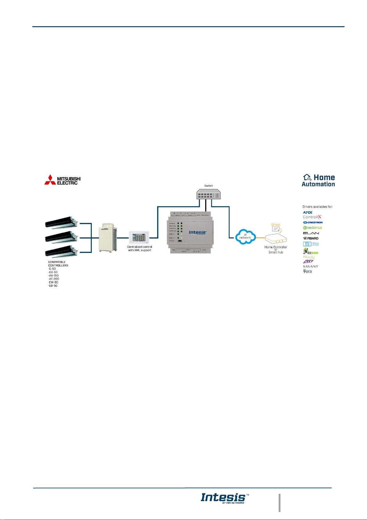
This document describes the integration of Mitsubishi Electric’s City Multi series air conditioning systems into Home
Automation systems using the Home Automation (WMP) to Mitsubishi Electric’s Centralized Controller
communication gateway.
The aim of this integration is to monitor and control Mitsubishi Electric City Multi air conditioning system, remotely,
from a Home Automation system. To do it so, Intesis communicates with Intesis WMP protocol, allowing controlling
and update the signals requested from the Home Automation hub.
Up to 50 indoor unit groups (1 Centralized Controller) or 100 indoor unit groups (2 Centralized Controllers) are
supported, depending on the version of the gateway.
This document assumes that the user is familiar with Home Auotomation (WMP) and Mitsubishi Electric technologies
and their technical terms.
Integration of Mitsubishi's Centralized Controller into
Home Automation (WMP) control systems
Page 6
IntesisTM Home Automation (WMP) – Mitsubishi Electric CC User Man r1.0 EN
© HMS Industrial Networks S.L.U. - All rights reserved
This information is subject to change without notice
URL https://www.intesis.com
6 / 22
1.2. Functionality
IntesisTM continuously monitors all the signals of the Centralized Controller groups for all configured signals and
keeps them updated in its memory available for reading and updating them towards the Home Automation system
via Intesis WMP protocol.
Commands toward the indoor units are permitted.
Each indoor unit is offered as a set of WMP commands.
Element
Max
Notes
Number of MNET Centralized
Controllers
2
Number of independent centralized controllers (if
expansion controllers are present, each expansion
controller counts as a single centralized controller)
Number of City Multi groups
100
50 groups for each centralized controller are supported
Max number of variables per group
8
Number of available signals will vary according to unit type
Max number of variables per Centralized
Controller
401
1 global signal (error signaling) + 8 signals/group x 50
groups
This gateway allows to control IC and FU Mitsubishi Electric units. Any other unit type might be detected for the
gateway, but no control is available for them. This applies to LC, BU, WH, CEh and sc units.
1.3. Capacity of Intesis
Element
Max.
Notes
Number of groups
100*
Number of groups that can be controlled through Intesis
* There are different models of Intesis WMP – Mitsubishi Electric Centralized Controller each one with different
capacity. The table above shows the capacity for the top model (with maximum capacity).
The 2 different models allow integrating respectively: 1 or 2 Centralized Controllers.
Their order codes are:
▪ INMBSMIT050C000, Model supporting up to 50 City Multi groups.
▪ INMBSMIT100C000, Model supporting up to 100 City Multi groups.
Page 7

IntesisTM Home Automation (WMP) – Mitsubishi Electric CC User Man r1.0 EN
© HMS Industrial Networks S.L.U. - All rights reserved
This information is subject to change without notice
URL https://www.intesis.com
7 / 22
2. Intesis WMP interface
In this section, a common description for all Intesis WMP series gateways is given, from the point of view of the
Home Automation system which is called from now on internal system. Connection with the Mitsubishi Electric CC
is also called from now on external system.
There is a specific Home Automation (WMP) manual available about WMP protocol with available examples. Here
is included the specific information regarding to WMP protocol and its integration in this product, for further
explanations, refer to the refered WMP manual available in www.intesis.com.
2.1. HVAC WMP Commands supported
Intesis WMP commands SET/CHN/GET can be used with the different WMP functions.
2.2. HVAC WMP Functions allowed
Depending on the signal, different commands are allowed. WMP protocol uses different functions to refer to different
signals of the HVAC system.
In the table below are listed the available WMP signals for the HVAC control, the function to identify the signal, its
available values and the commands allowed to interact with them.
Consider that Mitsubishi Electric units type LC, BU, WH, Ceh and cs are not controllable by this gateway.
CENTRALIZED CONTROLLERS
Signal description
Function
Values
Commands
Centralized controller communication error
ERROROU
OK/ERR
CHN/GET
INDIVIDUAL UNITS
Signal description
Function
Values
Commands
On/Off
ONOFF
ON/OFF
SET/CHN/GET
Operation Mode
MODE
HEAT/COOL/FAN/DRY/AUTO**
SET/CHN/GET
Fan Speed
FANSP
1/2/3/4/AUTO
SET/CHN/GET
Vane Position*
VANEUD
1/2/3/4/5/AUTO/SWING
SET/CHN/GET
Temperature Setpoint (x10) (ºC)
SETPTEMP
(ºC)
SET/CHN/GET
AC Ambient Temperature (x10) (-35..92,5ºC)
AMBTMP
(ºC)
CHN/GET
Unit Error code (0-No Error,X-Error)
ERRCODE
0/X (see user manual)
CHN/GET
Error IU
ERRSTATUS
OK/ERR
CHN/GET
*FU units have no vane positioning signal available.
**AUTO HEAT and AUTO COOL are reported as AUTO.
2.3. Link with Home Automation system
This gateway supports one IP connection to communicate with the home automation hub or central controller but
allows to communicate with several AC units. To identify the ac unit to control from the Home Automation side, WMP
protocol has implemented the acnum parameter. Basically, this parameter links the home automation side identifying
the AC unit to control in the AC system.
Given an AC unit, all its individual signals have one unique acnum and this number is always different among all the
ac units configured in the gateway. Only in some specific cases, outdoor units might share the acnum with one
indoor unit as the commands are independent between themselves.
Acnum is given in the configuration section. See 4.2.5 MITSUBISHI ELECTRIC CONFIGURATION for more information.
Page 8

IntesisTM Home Automation (WMP) – Mitsubishi Electric CC User Man r1.0 EN
© HMS Industrial Networks S.L.U. - All rights reserved
This information is subject to change without notice
URL https://www.intesis.com
8 / 22
3. Connections
Find below information regarding the Intesis connections available.
Power Supply
Must use NEC Class 2 or Limited Power Source (LPS) and
SELV rated power supply.
If using DC power supply:
Respect polarity applied of terminals (+) and (-). Be sure the
voltage applied is within the range admitted (check table
below). The power supply can be connected to earth but only
through the negative terminal, never through the positive
terminal.
If using AC power supply:
Make sure the voltage applied is of the value admitted (24
Vac). Do not connect any of the terminals of the AC power
supply to earth, and make sure the same power supply is not
supplying any other device.
Ethernet / Home Automation (WMP) / Mitsubishi
Centralized Controller / Console (UDP & TCP)
Connect the cable coming from the IP network to the
connector ETH of the gateway. Use an Ethernet CAT5 cable.
If communicating through the LAN of the building, contact the
network administrator and make sure traffic on the port used
is allowed through all the LAN path (check the gateway user
manual for more information). Default IP is 192.168.100.246.
DHCP is enabled by default.
PortA / Free
PortB / Free
Console Port
Connect a mini-type B USB cable from your computer to the gateway to allow communication between the
Configuration Software and the gateway. Remember that Ethernet connection is also allowed. Check the user
manual for more information.
USB
Connect a USB storage device (not HDD) if required. Check the user manual for more information.
Ensure proper space for all connectors when mounted (see 6 DIMENSIONS).
Ethernet
Mitsubishi CC
Home Automation (WMP)
Page 9

IntesisTM Home Automation (WMP) – Mitsubishi Electric CC User Man r1.0 EN
© HMS Industrial Networks S.L.U. - All rights reserved
This information is subject to change without notice
URL https://www.intesis.com
9 / 22
3.1. Power device
The first step to perform is to power up the device. To do so, a power supply working with any of the voltage range
allowed is needed (check 5 ELECTRICAL & MECHANICAL FEATURES). Once connected the ON led will turn on.
WARNING! To avoid earth loops that can damage the gateway, and/or any other equipment connected to it, we
strongly recommend:
• The use of DC power supplies, floating or with the negative terminal connected to earth. Never use a
DC power supply with the positive terminal connected to earth.
• The use of AC power supplies only if they are floating and not powering any other device.
3.2. Connect to Mitsubishi’s Centralized Controller(s)
Connect the communication cable coming from the network hub, switch or direct from the Centralized Controller to
the Ethernet port (¡Error! No se encuentra el origen de la referencia.) of the gateway. The cable to be used shall
be a straight Ethernet UTP/FTP CAT5 cable.
In case there is no response from Mitsubishi Centralized Controller to the frames sent by the gateway, check that it
is operative and reachable from the network connection used by the gateway. Check the gateway’s Ethernet
interface sending Pings to its IP address using a PC connected to the same Ethernet IP network. If the problem
persists communicating through the LAN of the building, contact the network administrator and make sure traffic on
the port used is allowed through all the LAN path.
Intesis Modbus Server – Mitsubishi Centralized Controller comes with DHCP functionality enabled by default.
3.3. Connection to Home Automation (WMP)
The gateways Ethernet port connection is used for the Home Automation (WMP) TCP communication. Connect the
communication cable coming from the network hub or switch to the Ethernet port of Intesis. The cable to be used
shall be a straight Ethernet UTP/FTP CAT5 cable.
TCP port to use (default 502) and keep alive period must be configured.
IP settings of the gateway (DHCP status, own IP, netmask and default gateway) must be configured as well.
3.4. Connection to PC (Configuration tool)
This action allows the user to have access to configuration and monitoring of the device (more information can be
found in the configuration tool User Manual). Two methods to connect to the PC can be used:
• Ethernet: Using the Ethernet port of Intesis.
• USB: Using the console port of Intesis, connect a USB cable from the console port to the PC.
Page 10
IntesisTM Home Automation (WMP) – Mitsubishi Electric CC User Man r1.0 EN
© HMS Industrial Networks S.L.U. - All rights reserved
This information is subject to change without notice
URL https://www.intesis.com
10 / 22
4. Set-up process and troubleshooting
4.1. Pre-requisites
It is necessary to have the Home Automation system (normally a central hub) operative, configured and properly
connected to the Ethernet port of the gateway and the Mitsubishi Centralized Controller with Ethernet connected to
the gateway.
Connectors, connection cables, PC for the Configuration Tool usage and other auxiliary material, if needed, are not
supplied by Intesis for this standard integration.
Items supplied by HMS Networks for this integration are:
• Intesis gateway.
• Link to download the configuration tool.
• USB Console cable to communicate with Intesis.
• Product documentation.
4.2. Intesis MAPS. Configuration & monitoring tool for Intesis Home Automation (WMP)
series
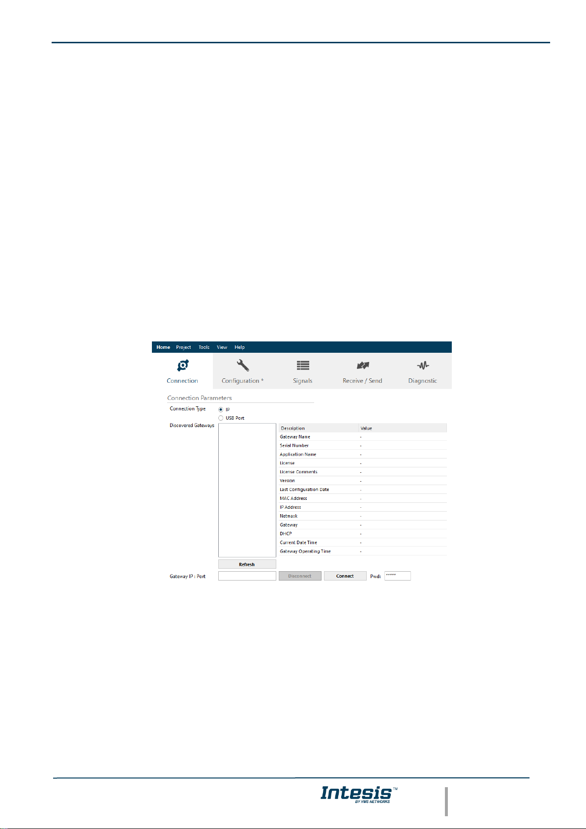
4.2.1. Connection
To configure the Intesis connection parameters press on the Connection button in the menu bar.
Figure 4.1 MAPS connection
Page 11

IntesisTM Home Automation (WMP) – Mitsubishi Electric CC User Man r1.0 EN
© HMS Industrial Networks S.L.U. - All rights reserved
This information is subject to change without notice
URL https://www.intesis.com
11 / 22
4.2.2. Configuration tab
Select the Configuration tab to configure the connection parameters. Three subsets of information are shown in
this window: General (Gateway general parameters), WMP (Home Automation system) and Mitsubishi Electric
(Mitsubishi Electric interface parameters).
Figure 4.2 Intesis MAPS configuration tab
4.2.3. General configuration
These are the general settings of the gateway. Here you can find:
• General configuration
In this section you can include a name and description to identify the gateway.
• Connection
Here are the settings related to the IP address (via DHCP/specific IP address) and the password set for the IP
configuration of the gateway in MAPS.
• USB Host
In this section it is possible to configure the different settings for the USB host port.
4.2.4. Home Automation (WMP) system configuration
These are the settings available for the Home Automation system (WMP communication):
Page 12

IntesisTM Home Automation (WMP) – Mitsubishi Electric CC User Man r1.0 EN
© HMS Industrial Networks S.L.U. - All rights reserved
This information is subject to change without notice
URL https://www.intesis.com
12 / 22
Figure 4.3 Intesis MAPS Home Automation configuration tab
1. Available commands
This is an informative section displaying all commands available for the WMP communication.
2. TCP Configuration.
This section allows to configure the TCP settings for the WMP communication with the Home Automation system.
• Port: WMP TCP communication port setting. Default port 3310.
• Keep Alive. Set the time of inactivity to send a keep Alive message. Default 10 minutes.
4.2.5. Mitsubishi Electric configuration
Set parameters for the connection with Mitsubishi Electric installation.
Figure 4.4 Intesis MAPS Mitsubishi Electric configuration tab
Centralized controller settings
Page 13

IntesisTM Home Automation (WMP) – Mitsubishi Electric CC User Man r1.0 EN
© HMS Industrial Networks S.L.U. - All rights reserved
This information is subject to change without notice
URL https://www.intesis.com
13 / 22
Figure 4.5 Intesis MAPS Centralized Controller setings
Each centralized controller you have available the following settings for its configuration:
• IP. IP address of the centralized controller.
• Description. Descriptive name to easy identification the centralized controller (for example, ‘floors 1-5, etc).
• Controller type: Select if Centralized Controller has direct connection, or it is an Expansion Controller.
Possible values are:
o Controller Direct Connection
o Expansion Controller 1
o Expansion Controller 2
o Expansion Controller 3
• Centralized Controller Model: Select the Centralized Controled model. Possible values are:
o AG-150A, GB-50ADA or older
o EB-50GU
o AE-200, EW-50 or newer
• Old Model Compatibility: Set up if EB-50GU or AE-200 (or newer) Centralized Controller has been setup
in ‘Old Compatibility’ mode.
For each Centralized Controller, it must also be selected the groups that will be monitored/controlled using Intesis.
You can do it manually in ‘Controllers Configuration’ section, by unfolding the corresponding ‘Centralized Controller’
in the list of controllers.
You can also scan for available groups under the IP of the Centralized Controller:
Figure 4.6 Intesis MAPS Selection of active groups in Centralized Controller
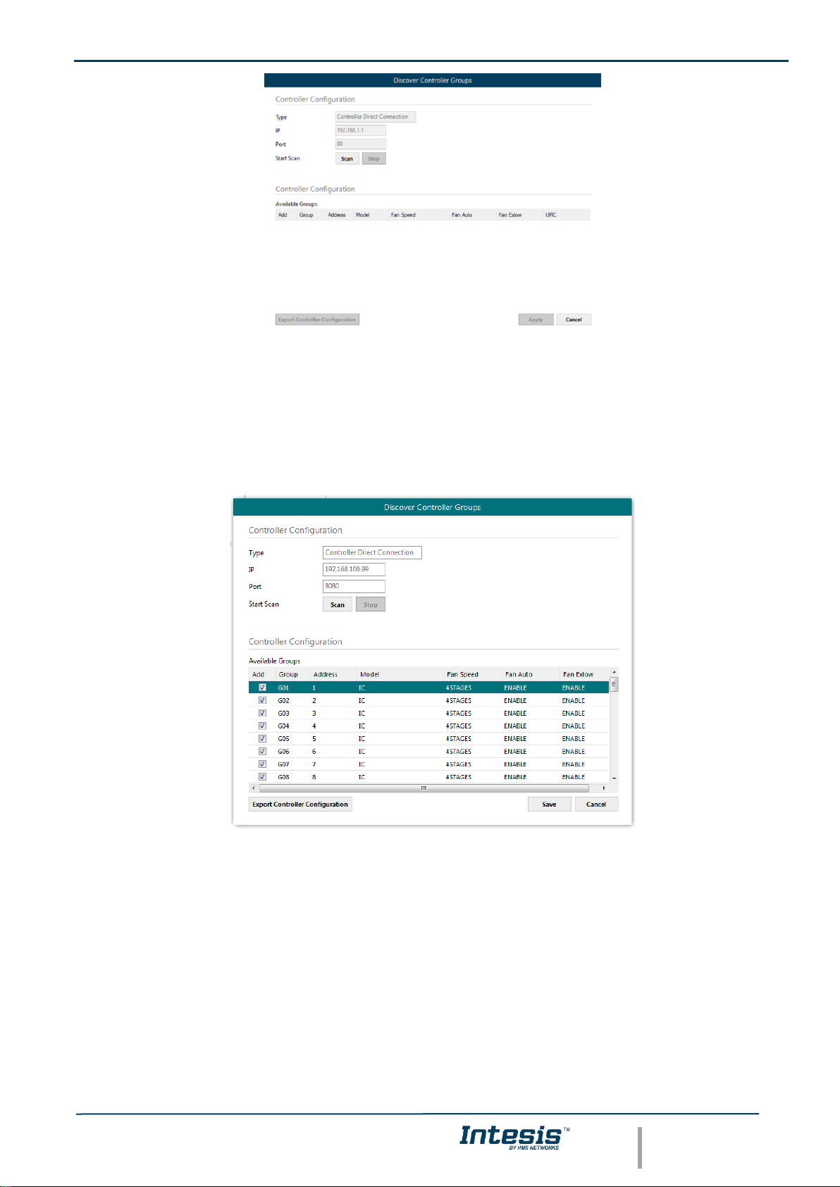
By pressing the ‘Scan’ button, ‘Discover Controller Groups’ window will appear:
Page 14
IntesisTM Home Automation (WMP) – Mitsubishi Electric CC User Man r1.0 EN
© HMS Industrial Networks S.L.U. - All rights reserved
This information is subject to change without notice
URL https://www.intesis.com
14 / 22
Figure 4.7 Discover control groups window
By pressing ‘Scan’ button, configured Centralized Controller will be scanned for available control groups. Error
window will appear if there is a problem in the connection with the Centralized Controller (Ethernet cable not
connected, wrong IP address for Centralized Controller, PC Monitoring license in Centralized Controller is not active,
…).
A progress bar will appear during the scan, which will take a few seconds (up to 1 or 2 minutes). After scan is
completed, detected groups will be shown in the ‘Available Groups’ area, as follows:
Figure 4.8 Scan results window
From available groups, mark the checkbox under column ‘Add’ to select these groups as active and configured in
the Centralized Controller.
By pressing the ‘Save’ button, information will be passed to previous ‘Controllers Configuration’ window in MAPS.
‘Discover Control Groups’ also allows to Export Controller Configuration, which will generate a text file with the active
groups in the controller, for documentation and support purposes.
Group configuration settings
Once the list of active groups is filled, parameters for each group must be configured. For doing so, select each
group in the list:
Page 15

IntesisTM Home Automation (WMP) – Mitsubishi Electric CC User Man r1.0 EN
© HMS Industrial Networks S.L.U. - All rights reserved
This information is subject to change without notice
URL https://www.intesis.com
15 / 22
Figure 4.9 Group configuration settings
Parameters that must be configured for each group are the following:
1. Description: Text description for the control Group
2. Unit Type: Possible values are:
Number
Model
Description
Availability: SCAN only or both (manual
selection + SCAN)
0
IC
Air conditioning indoor unit (VRF, Mseries, P-series and K-control unit)
Both
1
KIC
Indoor unit (K-control unit)
SCAN only
2
AIC
Indoor unit (P-Series)
SCAN only
3
LC
Lossnay
Both
4
FU
Outdoor-Air Processing unit
Both
5
BU
Air to Water Booster unit
Both
6
WH
Air to Water HEX unit
Both
7
CEh
Heat Pump
Both
8
DC
DiDo controller
SCAN only
9
AHC
ALL HVAC CONTROOLER
SCAN only
10
RC
ME remote controller (old type) /
Simple Remote Controller(old type)
SCAN only
11
ME
ME remote controller (new type)
SCAN only
12
CR
Simple Remote Controller (new type)
SCAN only
13
URC
New Remote Controller
SCAN only
14
EGW
EB-50
SCAN only
15
TR
AG-150,GB-50,G-5
SCAN only
16
AN
OnOff remote controller
SCAN only
17
GR
Group rermote controller
SCAN only
18
SR
System remote controller
SCAN only
19
ST
Schedule remote controller
SCAN only
20
SC
other controller
SCAN only
21 -
SCAN only
22
NONE
SCAN only
3. Setpoint type: Select if unit supports different setpoints according to operation mode, or it supports single
setpoint.
4. URC Controller: Select if unit has URC controller
Please note that the scan is taking the configiguration of “Unit Type”, “Num of Fan Speeds” and “URC Controller”
automatically so you might not need to modify these parameters after performing a scan.
Page 16

IntesisTM Home Automation (WMP) – Mitsubishi Electric CC User Man r1.0 EN
© HMS Industrial Networks S.L.U. - All rights reserved
This information is subject to change without notice
URL https://www.intesis.com
16 / 22
Advanced parameter settings
Finally, there is a set of advanced global parameters defining the communication of the Intesis with the centralized
controller. Find them in advanced parameters:
1. Polling Period: Time in milliseconds between each request sent to the Centralized Controller
2. Answer Timeout: Time in seconds that Intesis will wait for a response from Centralized Controller after
sending a single request for information through TCP/IP.
3. Controller Connection Timeout: After Intesis starts TCP/IP socket connection, time that the Intesis will
wait for the Centralized Controller to accept the socket request. For each individual request, Intesis starts a
new socket connection.
Acnum
Acnum is the parameter or number associated to every ac unit. This parameter identifies the ac unit from the home
automation side.
In this gateway, this number corresponds with the Mitsubishi Electric group number. This number cannot be edited
and is automatically generated during the manual or automatic (using SCAN) configuration process.
For the centralized controllers, acnum corresponds with the lowest Mitsubishi Electric group number of its configured
groups.
4.2.6. Signals
All available WMP signals, its corresponding description and other main parmaters are listed in the signals tab. The
acnum of every unit is also displayed in a column in the signals view.
Figure 4.10 Intesis MAPS Signals tab
4.2.7. Sending the configuration to Intesis
When the configuration is finished, follow the next steps.
1.- Save the project (Menu option Project->Save) on your hard disk (more information in Intesis MAPS User
Manual).
2.- Go to tab ‘Receive / Send’ of MAPS, and in Send section, press Send button. Intesis will reboot
automatically once the new configuration is loaded.
Page 17

IntesisTM Home Automation (WMP) – Mitsubishi Electric CC User Man r1.0 EN
© HMS Industrial Networks S.L.U. - All rights reserved
This information is subject to change without notice
URL https://www.intesis.com
17 / 22
Figure 4.11 Intesis MAPS Receive/Send tab
After any configuration change, do not forget to send the configuration file to the Intesis using the
Send button in the Receive / Send section.
4.2.8. Diagnostic
To help integrators in the commissioning tasks and troubleshooting, the Configuration Tool offers some specific
tools and viewers.
To start using the diagnostic tools, connection with the Gateway is required.
The Diagnostic section is composed by two main parts: Tools and Viewers.
• Tools
Use the tools section to check the current hardware status of the box, log communications into
compressed files to be sent to the support, change the Diagnostic panels’ view or send commands
to the gateway.
• Viewers
To check the status, viewer for the Internal and External protocols are available. It is also available
a generic Console viewer for general information about communications and the gateway status
and finally a Signals Viewer to simulate the BMS behavior or to check the current values in the
system.
Figure 4.12 Diagnostic
More information about the Diagnostic section can be found in the Configuraion Tool manual.
4.2.9. Set-up procedure
Page 18

IntesisTM Home Automation (WMP) – Mitsubishi Electric CC User Man r1.0 EN
© HMS Industrial Networks S.L.U. - All rights reserved
This information is subject to change without notice
URL https://www.intesis.com
18 / 22
1. Install Intesis MAPS on your laptop, use the setup program supplied for this and follow the instructions given by
the Installation wizard.
2. Install Intesis in the desired installation site. Installation can be on DIN rail or on a stable not vibrating surface
(DIN rail mounted inside a metallic industrial cabinet connected to ground is recommended).
3. For the Home Automation (WMP) communication, connect the communication cable coming from the Ethernet
port of the WMP TCP installation to the port marked as Ethernet Port of Intesis. More details in 3 CONNECTIONS.
4. Connect the communication cable coming from Mitsubishi Electric’s Centralized Controller network to the port
marked as Ethernet Port of Intesis. More details in 3 CONNECTIONS.
5. Power up Intesis. The supply voltage can be 9 to 36 Vdc or just 24 Vac. Take care of the polarity of the supply
voltage applied.
WARNING! To avoid earth loops that can damage Intesis and/or any other equipment connected to it, we
strongly recommend:
• The use of DC power supplies, floating or with the negative terminal connected to earth. Never use a
DC power supply with the positive terminal connected to earth.
• The use of AC power supplies only if they are floating and not powering any other device.
6. If you want to connect using IP, connect the Ethernet cable from the laptop PC to the port marked as Ethernet
of Intesis. More details in 3 CONNECTIONS.
If you want to connect using USB, connect the USB cable from the laptop PC to the port marked as Console of
Intesis. More details in 3 CONNECTIONS.
7. Open Intesis MAPS, create a new project selecting a copy of the one named IBOX-WMP-ME-Template.
8. Modify the configuration as desired, save it and download the configuration file to Intesis as explained in the
Intesis MAPS user manual.
9. Visit the Diagnostic section, enable COMMS () and check that there is communication activity, some TX frames
and some other RX frames. This means that the communication with the Centralized Controller and Home
Automation hub or controller is OK. In case there is no communication activity between Intesis and Home
Automationhhub or controller and/or the ME centralized controller, check that those are operative: check the
baud rate, the communication cable used to connect all devices and any other communication parameter.
Page 19

IntesisTM Home Automation (WMP) – Mitsubishi Electric CC User Man r1.0 EN
© HMS Industrial Networks S.L.U. - All rights reserved
This information is subject to change without notice
URL https://www.intesis.com
19 / 22
Figure 4.13 Enable COMMS
Page 20

IntesisTM Home Automation (WMP) – Mitsubishi Electric CC User Man r1.0 EN
© HMS Industrial Networks S.L.U. - All rights reserved
This information is subject to change without notice
URL https://www.intesis.com
20 / 22
5. Electrical & Mechanical Features
Enclosure
Plastic, type PC (UL 94 V-0)
Net dimensions (dxwxh): 90x88x56 mm
Recommended space for installation (dxwxh): 130x100x100mm
Color: Light Grey. RAL 7035
Battery
Size: Coin 20mm x 3.2mm
Capacity: 3V / 225mAh
Type: Manganese Dioxide Lithium
Mounting
Wall.
DIN rail EN60715 TH35.
Console Port
Mini Type-B USB 2.0 compliant
1500VDC isolation
Terminal
Wiring
(for power supply
and low-voltage
signals)
Per terminal: solid wires or stranded wires (twisted or with ferrule)
1 core: 0.5mm
2
… 2.5mm
2
2 cores: 0.5mm
2
… 1.5mm
2
3 cores: not permitted
If cables are more than 3.05 meters long, Class 2 cable is required.
USB port
Type-A USB 2.0 compliant
Only for USB flash storage device
(USB pen drive)
Power consumption limited to 150mA
(HDD connection not allowed)
Power
1 x Plug-in screw terminal block (3 poles)
9 to 36VDC +/-10%, Max.: 140mA.
24VAC +/-10% 50-60Hz, Max.: 127mA
Recommended: 24VDC
Push Button
Button A: Not used
Button B: Not used
Operation
Temperature
0°C to +60°C
Ethernet
1 x Ethernet 10/100 Mbps RJ45
2 x Ethernet LED: port link and activity
Operational
Humidity
5 to 95%, no condensation
Port A
2 x Plug-in screw terminal block green (2 poles)
Reserved for future use
Protection
IP20 (IEC60529)
LED
Indicators
10 x Onboard LED indicators
2 x Run (Power)/Error
2 x Ethernet Link/Speed
2 x Port A TX/RX
2 x Port B TX/RX
1 x Button A indicator
1 x Button B indicator
Switch A
(SWA)
1 x DIP-Switch for EIA485 configuration:
Reserved for future use
PORT B
1 x Serial EIA232 (SUB-D9 male connector)
Not used
1 x Serial EIA485 Plug-in screw terminal block (3 poles)
A, B, SGND (Reference ground or shield)
1500VDC isolation from other ports
Switch B
(SWB)
1 x DIP-Switch for serial EIA485 configuration:
Position 1:
ON: 120 Ω termination active
Off: 120 Ω termination inactive (default)
Position 2-3:
ON: Polarization active
Off: Polarization inactive (default)
Page 21

IntesisTM Home Automation (WMP) – Mitsubishi Electric CC User Man r1.0 EN
© HMS Industrial Networks S.L.U. - All rights reserved
This information is subject to change without notice
URL https://www.intesis.com
21 / 22
6. Dimensions
Recommended available space for its installation into a cabinet (wall or DIN rail mounting), with space enough for
external connections
100 mm (h)
100 mm (w)
130 mm (d)
56 mm (h)
88 mm (w)
90 mm (d)
Page 22

IntesisTM Home Automation (WMP) – Mitsubishi Electric CC User Man r1.0 EN
© HMS Industrial Networks S.L.U. - All rights reserved
This information is subject to change without notice
URL https://www.intesis.com
22 / 22
7. AC Unit Types compatibility
The gateway is compatible with Mitsubishi Electric City Multi systems.
 Loading...