

Page 1
Hisense Air Conditioning
Gateway for the integration of Hisense VRF systems into Modbus (RTU and TCP)
systems
USER MANUAL
Issue date: 11/2018 r1.0 ENGLISH
Page 2

IntesisTM Modbus Server – HISENSE VRF User Manual r1.0 EN
© HMS Industrial Networks S.L.U - All rights reserved
This information is subject to change without notice
URL https://www.intesis.com
2 / 30
Important User Information
Disclaimer
The information in this document is for informational purposes only. Please inform HMS Industrial Networks of any
inaccuracies or omissions found in this document. HMS Industrial Networks disclaims any responsibility or liability
for any errors that may appear in this document.
HMS Industrial Networks reserves the right to modify its products in line with its policy of continuous product
development. The information in this document shall therefore not be construed as a commitment on the part of
HMS Industrial Networks and is subject to change without notice. HMS Industrial Networks makes no commitment
to update or keep current the information in this document.
The data, examples and illustrations found in this document are included for illustrative purposes and are only
intended to help improve understanding of the functionality and handling of the product. In view of the wide range
of possible applications of the product, and because of the many variables and requirements associated with any
particular implementation, HMS Industrial Networks cannot assume responsibility or liability for actual use based on
the data, examples or illustrations included in this document nor for any damages incurred during installation of the
product. Those responsible for the use of the product must acquire sufficient knowledge in order to ensure that the
product is used correctly in their specific application and that the application meets all performance and safety
requirements including any applicable laws, regulations, codes and standards. Further, HMS Industrial Networks will
under no circumstances assume liability or responsibility for any problems that may arise as a result from the use of
undocumented features or functional side effects found outside the documented scope of the product. The effects
caused by any direct or indirect use of such aspects of the product are undefined and may include e.g. compatibility
issues and stability issues.
Page 3

IntesisTM Modbus Server – HISENSE VRF User Manual r1.0 EN
© HMS Industrial Networks S.L.U - All rights reserved
This information is subject to change without notice
URL https://www.intesis.com
3 / 30
Gateway for the integration of Hisense VRF systems into
Modbus (RTU and TCP) systems.
ORDER CODE
LEGACY ORDER CODE
INMBSHIS016O000
HS-AC-MBS-16
INMBSHIS064O000
HS-AC-MBS-64
Page 4
IntesisTM Modbus Server – HISENSE VRF User Manual r1.0 EN
© HMS Industrial Networks S.L.U - All rights reserved
This information is subject to change without notice
URL https://www.intesis.com
4 / 30
INDEX
1. Description ............................................................................................................................................................ 5
Introduction ................................................................................................................................................... 5
1.1 Functionality ..................................................................................................................................................... 6
Capacity of Intesis......................................................................................................................................... 7
2. Modbus interface .................................................................................................................................................. 8
Functions supported ..................................................................................................................................... 8
Modbus RTU ................................................................................................................................................. 8
Modbus TCP ................................................................................................................................................. 8
Modbus Address Map ................................................................................................................................... 9
3. Connections ........................................................................................................................................................ 12
Power device .............................................................................................................................................. 13
Connect to Hisense VRF installation .......................................................................................................... 13
Connection to Modbus ................................................................................................................................ 13
1.9.1 Modbus TCP ....................................................................................................................................... 13
1.9.2 Modbus RTU ....................................................................................................................................... 13
Connection to PC (Configuration tool) ........................................................................................................ 14
4. Set-up process and troubleshooting ................................................................................................................... 15
Pre-requisites .............................................................................................................................................. 15
Intesis MAPS. Configuration & monitoring tool for Intesis Modbus series ................................................. 15
1.12.1 Introduction.......................................................................................................................................... 15
1.12.2 Connection .......................................................................................................................................... 15
1.12.3 Configuration tab ................................................................................................................................. 16
1.12.4 Modbus Slave configuration ................................................................................................................ 16
1.12.5 Hisense configuration .......................................................................................................................... 18
1.12.6 Signals ................................................................................................................................................. 20
1.12.7 Sending the configuration to Intesis .................................................................................................... 21
1.12.8 Diagnostic............................................................................................................................................ 21
1.12.9 Set-up procedure ................................................................................................................................ 22
5. Electrical & Mechanical Features ....................................................................................................................... 24
6. Dimensions ......................................................................................................................................................... 25
7. AC Unit Types compatibility................................................................................................................................ 26
8. Error codes for Indoor and Outdoor Units .......................................................................................................... 27
Page 5
IntesisTM Modbus Server – HISENSE VRF User Manual r1.0 EN
© HMS Industrial Networks S.L.U - All rights reserved
This information is subject to change without notice
URL https://www.intesis.com
5 / 30
1. Description
Introduction
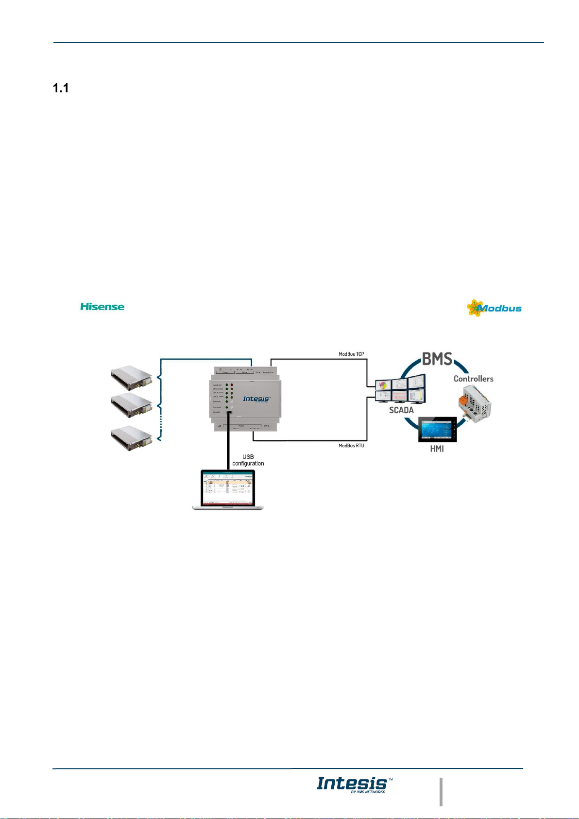
This document describes the integration of Hisense VRF air conditioning systems into Modbus compatible devices
and systems using using gateway the Intesis Modbus Server to Hisense VRF communication gateway.
The aim of this integration is to monitor and control Hisense air conditioning systems, remotely, from a Control
Center using any commercial SCADA or monitoring software that includes a Modbus Master driver (RTU and/or
TCP). To do it so, Intesis performs as a Modbus Server, allowing poll and write requests from any Modbus master
device.
Intesis makes available the Hisense air conditioning system indoor units’ datapoints through independent Modbus
registers.
Up to 64 indoor units supported, depending on product version.
This document assumes that the user is familiar with Modbus and Hisense technologies and their technical terms.
Integration of Hisense’s compatible systems into Modbus systems
Page 6
IntesisTM Modbus Server – HISENSE VRF User Manual r1.0 EN
© HMS Industrial Networks S.L.U - All rights reserved
This information is subject to change without notice
URL https://www.intesis.com
6 / 30
1.1 Functionality
IntesisTM continuously monitors Hisense VRF network for all configured signals and keeps the updated status of all
of them in its memory, ready to be served when requested from the Modbus master.
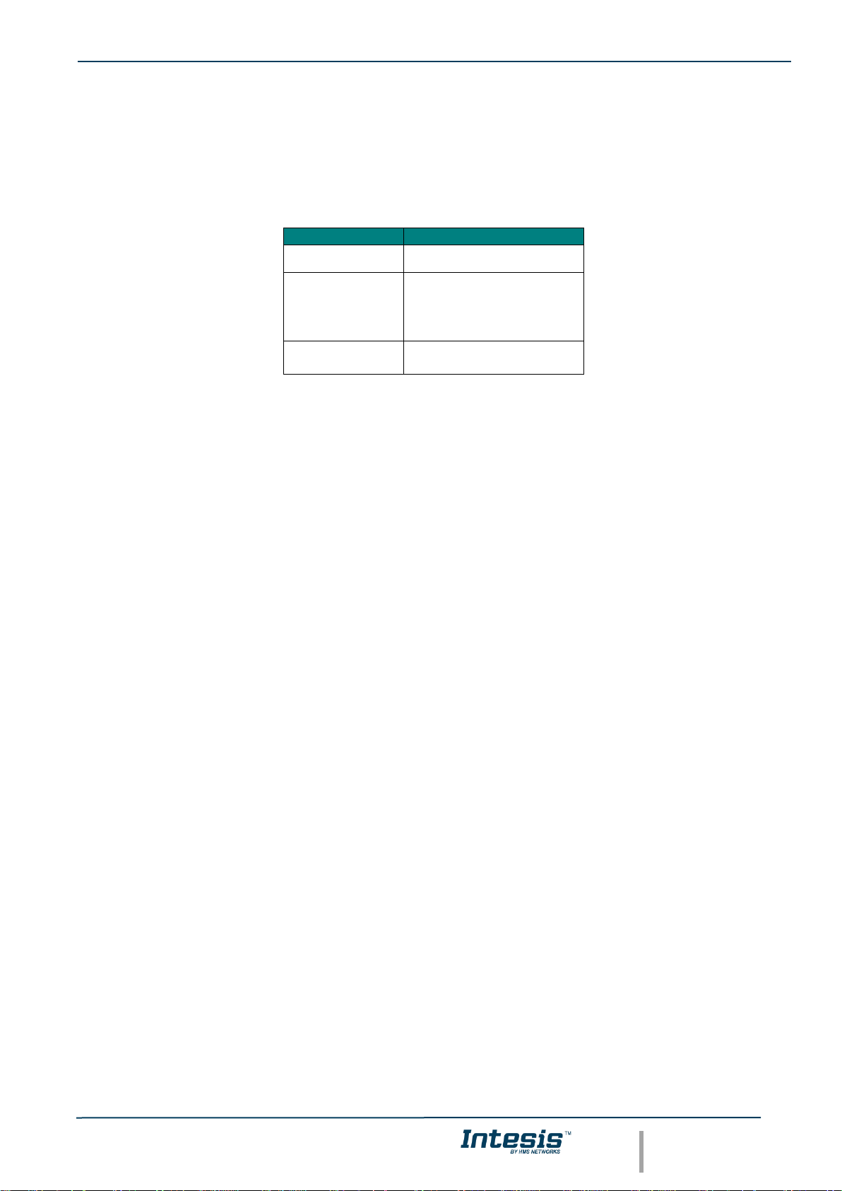
Commands toward the indoor units are permitted.
Each indoor unit is offered as a set of MBS objects.
Element
Object supported
Outdoor Unit
• Status
Indoor Unit
• Status
• Command
• Communication
status
General signals
(all units)
• Command
Page 7

IntesisTM Modbus Server – HISENSE VRF User Manual r1.0 EN
© HMS Industrial Networks S.L.U - All rights reserved
This information is subject to change without notice
URL https://www.intesis.com
7 / 30
Capacity of Intesis
Element
Max.
Notes
Number of indoor units
64 *
Number of indoor units that can be controlled through Intesis
* There are different models of Intesis MBS – Hisense VRF each one with different capacity. The table above shows
the capacity for the top model (with maximum capacity).
Their order codes are:
▪ INMBSHIS016O000: Model supporting up to 16 indoor units
▪ INMBSHIS064O000: Model supporting up to 64 indoor units
Page 8

IntesisTM Modbus Server – HISENSE VRF User Manual r1.0 EN
© HMS Industrial Networks S.L.U - All rights reserved
This information is subject to change without notice
URL https://www.intesis.com
8 / 30
2. Modbus interface
In this section, a common description for all Intesis Modbus series gateways is given, from the point of view of
Modbus system which is called from now on internal system. Connection with the Hisense VRF system is also called
from now on external system.
Functions supported
This part is common for Modbus RTU and TCP.
Modbus functions 03 and 04 (Read Holding Registers and Read Input Registers) can be used to read Modbus
registers.
Modbus functions 06 and 16 (Single Multiple Holding Registers and Write Multiple Holding Registers) can be used
to write Modbus registers.
Configuration of poll records is possible between Modbus addresses 0 and 20000. Addresses that are not defined
in section 2.2 (Modbus map of the device) are read-only and will always report 0.
Modbus error codes are supported, they will be sent whenever a non-valid Modbus address is queried.
All registers are 16-bit signed integer, in standard Modbus Big Endian (MSB/LSB) format.
Intesis supports Modbus RTU and Modbus TCP and both interfaces can be used simultaneously.
Modbus RTU
Both EIA485 and EIA232 physical layers are supported. Only the lines RX, TX and GND of the EIA232 connector
are used (TX and RX for EIA485).
Baud rate can be selected between 1200, 2400, 4800, 9600, 19200, 38400, 56700 and 115200. Parity (none, even
or odd) and stop bits (1 or 2) can be selected as well.
Modbus slave number must be configured and the physical connection (RS232 or RS485) can also be selected
Modbus TCP
TCP port to use (default is 502) and keep alive period must be configured.
IP settings of Intesis (DHCP status, own IP, net mask and default gateway) must be configured as well.
Page 9
IntesisTM Modbus Server – HISENSE VRF User Manual r1.0 EN
© HMS Industrial Networks S.L.U - All rights reserved
This information is subject to change without notice
URL https://www.intesis.com
9 / 30
Modbus Address Map
Modbus address from the formula is expressed in link layer format. This is, first register address is 0.
Modbus Address
First Address is 0
Read
/Write
Register/signal name
Possible values
0
W
On (all the units)
1-Set all the units On
1
W
Off (all the units)
1-Set all the units Off
2
W
Operation Mode Auto (all the units)
1-Set Auto Mode
3
W
Operation Mode Heat (all the units)
1-Set Heat Mode
4
W
Operation Mode Dry (all the units)
1-Set Dry Mode
5
W
Operation Mode Fan (all the units)
1-Set Fan Mode
6
W
Operation Mode Cool (all the units)
1-Set Cool Mode
7
W
Fan Speed Auto
(all the units)
1-Set Fan Speed Auto
8
W
Fan Speed Low
(all the units)
1-Set Fan Speed Low
9
W
Fan Speed Mid (all the units)
1-Set Fan Speed Mid
10
W
Fan Speed High (all the units)
1-Set Fan Speed High
11
W
Fan Speed High+ (all the units)
1-Set Fan Speed High+
12
W
Vane Position Auto (all the units)
1-Set Vane Position Auto
13
W
Vane Position 1 (all the units)
1-Set Vane Position 1
14
W
Vane Position 2 (all the units)
1-Set Vane Position 2
15
W
Vane Position 3 (all the units)
1-Set Vane Position 3
16
W
Vane Position 4 (all the units)
1-Set Vane Position 4
17
W
Vane Position 5 (all the units)
1-Set Vane Position 5
18
W
Vane Position 6 (all the units)
1-Set Vane Position 6
19
W
Vane Position 7 (all the units)
1-Set Vane Position 7
Page 10

IntesisTM Modbus Server – HISENSE VRF User Manual r1.0 EN
© HMS Industrial Networks S.L.U - All rights reserved
This information is subject to change without notice
URL https://www.intesis.com
10 / 30
20
W
Temperature Setpoint (x10ºC) (all units)
Cool: 19..30°C; Heat: 17..30°C
(OU*25)+10000+0
OU stands for Outdoor Unit
address from 1 to 64.
R
Communication Error OU
0-No error, 1-Error
(OU*25)+10000+1
R
Outdoor Air Temp.
-50..99 ºC
(OU*25)+10000+2
R
Comp.Top Temp.
0..200 ºC
(OU*25)+10000+3
R
Total Real Comp. Freq.
0..255 Hz
(OU*25)+10000+4
R
Total Comp. Current
0..255 A
(OU*25)+10000+5
R
Out Exp. Valve 1 Open
0..100 %
(OU*25)+10000+6
R
Discharge Pressure (x10ºC)
-5.0..9.9 MPa
(OU*25)+10000+7
R
Suction Pressure (x10ºC)
-5.0..9.9 MPa
(Ui*100)+0
Ui stands for Unit index number
as found in the Units
Configuration tab and ranges
from 1 to 64.
R/W
On/Off
0-Off, 1-On
(Ui*100)+1
R/W
Operation Mode
0-Auto, 1-Heat, 2-Dry. 3-Fan, 4-Cool
(Ui*100)+2
R/W
Fan Speed
0-Auto, 1-Low, 2-Mid, 3-High, 3-High+
(Ui*100)+3
R/W
Vane Position
0-Auto, 1-Pos1..7-Pos7
(Ui*100)+4
R/W
Temperature Setpoint (x10ºC)
Cool:19..30°C; Heat:17..30°C
(Ui*100)+5
R
Remote Sensor Temp. (x10ºC)
-63..63ºC
(Ui*100)+6
R
Inlet Temp. (x10ºC)
-63..63ºC
(Ui*100)+7
R
Outlet Temp. (x10ºC)
-63..63ºC
(Ui*100)+8
R
GasPipe Temp. (x10ºC)
-63..63ºC
(Ui*100)+9
R
LiquidPipe Temp. (x10ºC)
-63..63ºC
(Ui*100)+10
R
Unit Error code
Error code
(Ui*100)+11
R
Filter Alarm
0-Normal, 1-Alarm
(Ui*100)+12
W
Filter Alarm Reset
1-Reset
(Ui*100)+13
R
Communication Status
0-Not Exit, 1-Exist
Page 11

IntesisTM Modbus Server – HISENSE VRF User Manual r1.0 EN
© HMS Industrial Networks S.L.U - All rights reserved
This information is subject to change without notice
URL https://www.intesis.com
11 / 30
(Ui*100)+14
R/W
Allow On/Off from RC
0-Allow, 1-Not allow
(Ui*100)+15
R/W
Allow Mode from RC
0-Allow, 1-Not allow
(Ui*100)+16
R/W
Allow Setpoint from RC
0-Allow, 1-Not allow
(Ui*100)+17
R/W
Allow Fan from RC
0-Allow, 1-Not allow
(Ui*100)+18
R
Unit Type
0:Not Defined,1-SS,2-FC,3-VRF,4IU,5-ES
(Ui*100)+19
R
Unit Address
1..64
(Ui*100)+20
R
System Address
1..64
(Ui*100)+21
R
Dehumidification
0-Disabled, 1-Enabled
(Ui*100)+22
R/W
Dehumidification Correction
0-0, 1-(-1), 2-(-2)
(Ui*100)+23
R
Compresor Stop Cause
255-Operation Off, Other-See manual
(Ui*100)+24
R
Expansion Valve Open
0..100%
(Ui*100)+25
R
Operation Condition
0-Off, 1-Thermo Off, 2-Thermo On, 3Alarm
(Ui*100)+26
R
RC SW Temperature (x10ºC)
-63..63ºC
(Ui*100)+27
R
RC SW Config
0-Without RCS, 1-With RCS
Page 12

IntesisTM Modbus Server – HISENSE VRF User Manual r1.0 EN
© HMS Industrial Networks S.L.U - All rights reserved
This information is subject to change without notice
URL https://www.intesis.com
12 / 30
3. Connections
Find below information regarding the Intesis connections available.
Power Supply
Must use NEC Class 2 or Limited Power Source (LPS) and
SELV rated power supply.
If using DC power supply:
Respect polarity applied of terminals (+) and (-). Be sure the
voltage applied is within the range admitted (check table
below). The power supply can be connected to earth but
only through the negative terminal, never through the
positive terminal.
If using AC power supply:
Make sure the voltage applied is of the value admitted (24
Vac). Do not connect any of the terminals of the AC power
supply to earth, and make sure the same power supply is
not supplying any other device.
Ethernet / Modbus TCP (TCP) / Console (UDP & TCP)
Connect the cable coming from the IP network to the
connector ETH of the gateway. Use an Ethernet CAT5
cable. If communicating through the LAN of the building,
contact the network administrator and make sure traffic on
the port used is allowed through all the LAN path (check the
gateway user manual for more information). Default IP is
192.168.100.246. DHCP is enabled by default.
PortA / H-Link Hisense
Connect the H-Link terminals (TB2) of Hisense Outdoor Unit to the connectors A3 and A4 of gateway’s PortA.
There is no polarity to be respected.
PortB / Modbus-RTU RS485
Connect the EIA485 bus to connectors B1 (B+), B2 (A-) and B3 (SNGD) of gateway’s PortB. Respect the polarity.
Remember the characteristics of the standard EIA485 bus: maximum distance of 1200 meters, maximum 32 devices
connected to the bus, and in each end of the bus it must be a termination resistor of 120 Ω. Bus biasing and
termination resistor for EIA485 can be enabled for PortB by means of a dedicated DIP:
SW1:
ON: 120 Ω termination active
OFF: 120 Ω termination inactive (Default setting).
SW2+3:
ON: Polarization active
OFF: Polarization inactive (Default setting).
If the gateway is installed in one bus end, make sure that termination is active.
Console Port
Connect a mini-type B USB cable from your computer to the gateway to allow communication between the
Configuration Software and the gateway. Remember that Ethernet connection is also allowed. Check the user
manual for more information.
USB
Connect a USB storage device (not a HDD) if required. Check the user manual for more information.
Ensure proper space for all connectors when mounted (see section 6).
Page 13

IntesisTM Modbus Server – HISENSE VRF User Manual r1.0 EN
© HMS Industrial Networks S.L.U - All rights reserved
This information is subject to change without notice
URL https://www.intesis.com
13 / 30
Power device
The first step to perform is to power up the device. To do so, a power supply working with any of the voltage range
allowed is needed (check section 5). Once connected the ON led will turn on.
WARNING! In order to avoid earth loops that can damage the gateway, and/or any other equipment connected to
it, we strongly recommend:
• The use of DC power supplies, floating or with the negative terminal connected to earth. Never use a
DC power supply with the positive terminal connected to earth.
• The use of AC power supplies only if they are floating and not powering any other device.
Connect to Hisense VRF installation
Use the PortA connector in the top corner of the Intesis device in order to connect H-Link bus to the Intesis.
Remember to follow all safety precautions indicated by Hisense.
Connect the Hisense H-Link/TB2 bus to connectors A3 and A4 of gateway’s PortA. Bus is not sensitive to polarity.
Connection to Modbus
1.9.1 Modbus TCP
The gateways Ethernet port connection is used for Modbus TCP communication. Connect the communication cable
coming from the network hub or switch to the Ethernet port of Intesis. The cable to be used shall be a straight
Ethernet UTP/FTP CAT5 cable.
TCP port to use (default 502) and keep alive period must be configured.
IP settings of the gateway (DHCP status, own IP, netmask and default gateway) must be configured as well.
1.9.2 Modbus RTU
Connect the communication cable coming from the motbus network to the port marked as Port B of the Intesis.
Connect the EIA485 bus to connectors B1 (-), B2 (+) and B3 (SNGD) of gateway’s PortB. Respect the polarity.
Remember the characteristics of the standard EIA485 bus: maximum distance of 1200 meters, maximum 32 devices
(without repeaters) connected to the bus, and in each end of the bus it must be a termination resistor of 120 Ω. The
gateway has an internal bus biasing circuit that incorporates the termination resistor. Bus biasing and termination
resistor for EIA485 can be enabled for PortB by means of a dedicated DIP switch.
Page 14

IntesisTM Modbus Server – HISENSE VRF User Manual r1.0 EN
© HMS Industrial Networks S.L.U - All rights reserved
This information is subject to change without notice
URL https://www.intesis.com
14 / 30
Connection to PC (Configuration tool)
This action allows the user to have access to configuration and monitoring of the device (more information can be
found in the configuration tool User Manual). Two methods to connect to the PC can be used:
• Ethernet: Using the Ethernet port of Intesis.
• USB: Using the console port of Intesis, connect a USB cable from the console port to the PC.
Page 15

IntesisTM Modbus Server – HISENSE VRF User Manual r1.0 EN
© HMS Industrial Networks S.L.U - All rights reserved
This information is subject to change without notice
URL https://www.intesis.com
15 / 30
4. Set-up process and troubleshooting
Pre-requisites
It is necessary to have the Modbus RTU or TCP master/client device (BMS side device) operative and properly
connected to the corresponding port of the gateway and the Hisense VRF installation connected to their
corresponding ports as well.
Connectors, connection cables, PC for the Configuration Tool usage and other auxiliary material, if needed, are not
supplied by Intesis for this standard integration.
Items supplied by HMS Networks for this integration are:
• Intesis gateway.
• Link to download the configuration tool.
• USB Console cable to communicate with Intesis.
• Product documentation.
Intesis MAPS. Configuration & monitoring tool for Intesis Modbus series
1.12.1 Introduction
Intesis MAPS is a Windows® compatible software developed specifically to monitor and configure Intesis new
generation gateways.
The installation procedure and main functions are explained in the Intesis MAPS User Manual. This document can
be downloaded from the link indicated in the installation sheet supplied with the Intesis device or in the product
website at www.intesis.com
In this section, only the specific case of Hisense VRF to Modbus systems will be covered.
Please check the Intesis MAPS User Manual for specific information about the different parameters and how to
configure them.
1.12.2 Connection
To configure the Intesis connection parameters press on the Connection button in the menu bar.
Figure 4.1 MAPS connection
Page 16

IntesisTM Modbus Server – HISENSE VRF User Manual r1.0 EN
© HMS Industrial Networks S.L.U - All rights reserved
This information is subject to change without notice
URL https://www.intesis.com
16 / 30
1.12.3 Configuration tab
Select the Configuration tab to configure the connection parameters. Three subsets of information are shown in
this window: General (Gateway general parameters), Modbus Slave (Modbus interface configuration) and Hisense
(Hisense interface parameters).
Figure 4.2 Intesis MAPS configuration tab
1.12.4 Modbus Slave configuration
Set parameters of Modbus Slave interface of Intesis.
Page 17

IntesisTM Modbus Server – HISENSE VRF User Manual r1.0 EN
© HMS Industrial Networks S.L.U - All rights reserved
This information is subject to change without notice
URL https://www.intesis.com
17 / 30
Figure 4.3 Intesis MAPS Modbus configuration tab
1. Modbus Configuration
1.1. Modbus type selection. Select RTU, TCP or simultaneous RTU and TCP communication.
2. TCP Configuration.
2.1. Modbus TCP Port: Modbus TCP communication port setting. Default port 502.
2.2. Keep Alive. Set the time of inactivity to send a keep Alive message. Default 10 minutes.
3. RTU Configuration.
3.1. RTU bus connection type. Select the RTU connection type serial bus RS485 or 232.
3.2 Baudrate. Set the RTU bus communication speed. Default: 9600 bps.
• Available values: 1200, 2400, 4800, 9600,19200, 38400, 57600, 115200 bps.
3.3 Data Type. Set the Data-bit/parity/stop-bit. Default: 8bit/None/1.
• Available selection: 8bit/None/1, 8bit/Even/1, 8bit/Odd/1, 8bit/None/2.
3.4 Slave Number. Set the Modbus Slave address. Default slave address: 1.
• Valid address: 1..255.
Page 18

IntesisTM Modbus Server – HISENSE VRF User Manual r1.0 EN
© HMS Industrial Networks S.L.U - All rights reserved
This information is subject to change without notice
URL https://www.intesis.com
18 / 30
1.12.5 Hisense configuration
Set parameters for connection with Hisense’s installation.
Figure 4.4 Intesis MAPS Hisense configuration tab
In Units Configuration section you need to enter, for each unit:
• Active. If it’s active (checkbox at Unit xx), ranging from 1 to 64 indoor units that will be integrated (maximum
number of units will depend on Intesis model)
• IU address. Address 1..64 of Unit in Hisense H-Link bus.
• OU address. Address 1..64 of Outdoor Unit in Hisense H-Link bus.
• Description. Descriptive name to easy identification of the unit (for example, ‘living room floor 1 unit’, etc).
Additional to manual entry of each unit, autodiscover of present units in an H-Link installation is possible. To do so,
click button Scan. Following window will appear:
Page 19

IntesisTM Modbus Server – HISENSE VRF User Manual r1.0 EN
© HMS Industrial Networks S.L.U - All rights reserved
This information is subject to change without notice
URL https://www.intesis.com
19 / 30
Figure 4.5 Intesis MAPS Scan Hisense Units window
By pressing Scan button, connected Hisense H-Link bus will be scanned for available units. Error window will appear
if there is a problem in the connection with H-Link bus (units not powered, bus not connected, …).
A progress bar will appear during the scan, which will take up to a few minutes. After scan is complected, detected
units will be shown in available units as follows:
Figure 4.6 Intesis MAPS Scan Hisense Units window with scan results
Page 20

IntesisTM Modbus Server – HISENSE VRF User Manual r1.0 EN
© HMS Industrial Networks S.L.U - All rights reserved
This information is subject to change without notice
URL https://www.intesis.com
20 / 30
Select with its checkbox units to add (or replace) in installation, according to selection Replace Units / Add Units.
After units to be integrated are selected, click button Apply, and changes will appear in previous Units
Configuration window.
Figure 4.7 Intesis MAPS Hisense configuration tab after importing scan results
1.12.6 Signals
All available Modbus registers, its corresponding description and other main parmaters are listed in the signals tab.
Figure 4.8 Intesis MAPS Signals tab
Page 21

IntesisTM Modbus Server – HISENSE VRF User Manual r1.0 EN
© HMS Industrial Networks S.L.U - All rights reserved
This information is subject to change without notice
URL https://www.intesis.com
21 / 30
1.12.7 Sending the configuration to Intesis
When the configuration is finished, follow the next steps.
1.- Save the project (Menu option Project->Save) on your hard disk (more information in Intesis MAPS User
Manual).
2.- Go to tab ‘Receive / Send’ of MAPS, and in Send section, press Send button. Intesis will reboot
automatically once the new configuration is loaded.
Figure 4.9 Intesis MAPS Receive/Send tab
After any configuration change, do not forget to send the configuration file to the Intesis using the
Send button in the Receive / Send section.
1.12.8 Diagnostic
To help integrators in the commissioning tasks and troubleshooting, the Configuration Tool offers some specific
tools and viewers.
In order to start using the diagnostic tools, connection with the Gateway is required.
The Diagnostic section is composed by two main parts: Tools and Viewers.
• Tools
Use the tools section to check the current hardware status of the box, log communications into
compressed files to be sent to the support, change the Diagnostic panels’ view or send commands
to the gateway.
• Viewers
In order to check the current status, viewer for the Internal and External protocols are available. It
is also available a generic Console viewer for general information about communications and the
gateway status and finally a Signals Viewer to simulate the BMS behavior or to check the current
values in the system.
Page 22

IntesisTM Modbus Server – HISENSE VRF User Manual r1.0 EN
© HMS Industrial Networks S.L.U - All rights reserved
This information is subject to change without notice
URL https://www.intesis.com
22 / 30
Figure 4.10 Diagnostic
More information about the Diagnostic section can be found in the Configuraion Tool manual.
1.12.9 Set-up procedure
1. Install Intesis MAPS on your laptop, use the setup program supplied for this and follow the instructions given by
the Installation wizard.
2. Install Intesis in the desired installation site. Installation can be on DIN rail or on a stable not vibrating surface
(DIN rail mounted inside a metallic industrial cabinet connected to ground is recommended).
3. If using Modbus RTU, connect the communication cable coming from the EIA485 port of the Modbus RTU
installation to the port marked as Port B of Intesis (More details in section 3).
If using, Modbus TCP, connect the communication cable coming from the Ethernet port of the Modbus TCP
installation to the port marked as Ethernet Port of Intesis (More details in section 3).
4. Connect the communication cable coming from the Hisense VRF installation to the port marked as Port A of
Intesis (More details in section 3).
5. Power up Intesis. The supply voltage can be 9 to 36 Vdc or just 24 Vac. Take care of the polarity of the supply
voltage applied.
WARNING! In order to avoid earth loops that can damage Intesis and/or any other equipment connected to
it, we strongly recommend:
• The use of DC power supplies, floating or with the negative terminal connected to earth. Never use a
DC power supply with the positive terminal connected to earth.
• The use of AC power supplies only if they are floating and not powering any other device.
Page 23

IntesisTM Modbus Server – HISENSE VRF User Manual r1.0 EN
© HMS Industrial Networks S.L.U - All rights reserved
This information is subject to change without notice
URL https://www.intesis.com
23 / 30
6. If you want to connect using IP, connect the Ethernet cable from the laptop PC to the port marked as Ethernet
of Intesis (More details in section 3).
If you want to connect using USB, connect the USB cable from the laptop PC to the port marked as Console of
Intesis (More details in section 3).
7. Open Intesis MAPS, create a new project selecting a copy of the one named INMBSHIS---O000.
8. Modify the configuration as desired, save it and download the configuration file to Intesis as explained in the
Intesis MAPS user manual.
9. Visit the Diagnostic section, enable COMMS () and check that there is communication activity, some TX frames
and some other RX frames. This means that the communication with the Centralized Controller and Modbus
Master devices is OK. In case there is no communication activity between Intesis and the Centralized Controller
and/or Modbus devices, check that those are operative: check the baud rate, the communication cable used to
connect all devices and any other communication parameter.
Figure 4.11 Enable COMMS
Page 24

IntesisTM Modbus Server – HISENSE VRF User Manual r1.0 EN
© HMS Industrial Networks S.L.U - All rights reserved
This information is subject to change without notice
URL https://www.intesis.com
24 / 30
5. Electrical & Mechanical Features
Enclosure
Plastic, type PC (UL 94 V-0)
Net dimensions (dxwxh): 90x88x56 mm
Recommended space for installation (dxwxh): 130x100x100mm
Color: Light Grey. RAL 7035
Battery
Size: Coin 20mm x 3.2mm
Capacity: 3V / 225mAh
Type: Manganese Dioxide Lithium
Mounting
Wall.
DIN rail EN60715 TH35.
Console Port
Mini Type-B USB 2.0 compliant
1500VDC isolation
Terminal
Wiring
(for power supply
and
low-voltage
signals)
Per terminal: solid wires or stranded wires (twisted or with ferrule)
1 core: 0.5mm
2
… 2.5mm
2
2 cores: 0.5mm
2
… 1.5mm
2
3 cores: not permitted
If cables are more than 3.05 meters long, Class 2 cable is required.
USB port
Type-A USB 2.0 compliant
Only for USB flash storage device
(USB pen drive)
Power consumption limited to 150mA
(HDD connection not allowed)
Power
1 x Plug-in screw terminal block (3 poles)
9 to 36VDC +/-10%, Max.: 140mA.
24VAC +/-10% 50-60Hz, Max.: 127mA
Recommended: 24VDC
Push Button
Button A: Not used
Button B: Not used
Operation
Temperature
0°C to +60°C
Ethernet
1 x Ethernet 10/100 Mbps RJ45
2 x Ethernet LED: port link and activity
Operational
Humidity
5 to 95%, no condensation
Port A
1 x H-Link Plug-in screw terminal block orange (2 poles)
1500VDC isolation from other ports
1 x Plug-in screw terminal block green (2 poles)
Reserved for future use
Protection
IP20 (IEC60529)
LED
Indicators
10 x Onboard LED indicators
2 x Run (Power)/Error
2 x Ethernet Link/Speed
2 x Port A TX/RX
2 x Port B TX/RX
1 x Button A indicator
1 x Button B indicator
Switch A
(SWA)
1 x DIP-Switch for PORTA configuration:
Reserved for future use (leave OFF, default)
PORT B
1 x Serial EIA232 (SUB-D9 male connector)
Pinout from a DTE device
1500VDC isolation from other ports
(except PORT B: EIA485)
1 x Serial EIA485 Plug-in screw terminal block (3 poles)
A, B, SGND (Reference ground or shield)
1500VDC isolation from other ports
(except PORT B: EIA232)
Switch B
(SWB)
1 x DIP-Switch for serial EIA485 configuration:
Position 1:
ON: 120 Ω termination active
Off: 120 Ω termination inactive (default)
Position 2-3:
ON: Polarization active
Off: Polarization inactive (default)
100 mm (h)
100 mm (w)
130 mm (d)
Page 25

IntesisTM Modbus Server – HISENSE VRF User Manual r1.0 EN
© HMS Industrial Networks S.L.U - All rights reserved
This information is subject to change without notice
URL https://www.intesis.com
25 / 30
6. Dimensions
Recommended available space for its installation into a cabinet (wall or DIN rail mounting), with space enough for
external connections
100 mm (h)
100 mm (w)
130 mm (d)
56 mm (h)
88 mm (w)
90 mm (d)
Page 26

IntesisTM Modbus Server – HISENSE VRF User Manual r1.0 EN
© HMS Industrial Networks S.L.U - All rights reserved
This information is subject to change without notice
URL https://www.intesis.com
26 / 30
7. AC Unit Types compatibility
A list of Hisense unit model references compatible with INMBSHIS---O000 and their available features can be found
in:
https://www.intesis.com/docs/compatibilities/inxxxhis001r000_compatibility
Page 27

IntesisTM Modbus Server – HISENSE VRF User Manual r1.0 EN
© HMS Industrial Networks S.L.U - All rights reserved
This information is subject to change without notice
URL https://www.intesis.com
27 / 30
8. Error codes for Indoor and Outdoor Units
This list contains all possible values shown in Modbus register for “Error Code” for each indoor unit and outdoor
unit.
It must be taken into account that Outdoor Units are only able to reflect a single error for each indoor / outdoor unit
in the system. Thus, a unit having two or more active errors from that list will only report a single error code – the
one of the first error that has been detected.
Error
Code
Category
Content of Abnormality
Leading Cause
01
lndoor Unit
Activation of Protection Device (Float
Switch)
Activation of Float Switch
(High Water Level in Drain Pan,
Abnormality of Drain Pipe, Float Switch
or Drain Pan)
02
Outdoor Unit
Activation of Protection
Device (High Pressure
Cut)
Activation of PSH (Pipe
Clogging, Excessive
Refrigerant! lnert Gas
Mixing)
03
Transmission
Abnormality between lndoor and
Outdoor
incorrect Wiring, Loose Terminals,
Disconnect Wire, Blowout of Fuse,
Outdoor Unit Power OFF
04
Abnormality between lnverter PCB
and Outdoor PCB
lnverter PCB - Outdoor PCB
Transmission Failure (Loose
Connector, Wire Breaking,
Blowout of Fuse)
04.
Abnormality between Fan Controller
and Outdoor PCB
Fan Controller - Outdoor PCB
Transmission Failure (Loose
Connector, Wire Breaking,
Blowout of Fuse)
05
Supply Phase
Abnormality Power Source Phases
lncorrect Power
Source, Connection to
Reversed Phase, OpenPhase
06
Voltage
Abnormal lnverter Voltage
Outdoor Voltage Drop, insufficient Power
Capacity
06.
Abnormal Fan Controller Voltage
Outdoor Voltage Drop, lnsufficient Power
Capacity
07
Cycle
Decrease in Discharge Gas Superheat
Excessive Refrigerant! Charge,
Failure of Thermistor, lncorrect
Wiring, lncorrect Piping
Connection, Expansion Valve
Locking at Opened Position
(Disconnect Connector)
08
lncrease in Discharge Gas
Temperature
lnsufficient Refrigerant!
Charge, Pipe Clogging,
Failure of Thermistor,
lncorrect Wiring,
lncorrect Piping Connection,
Expansion Valve Locking at Closed
Page 28

IntesisTM Modbus Server – HISENSE VRF User Manual r1.0 EN
© HMS Industrial Networks S.L.U - All rights reserved
This information is subject to change without notice
URL https://www.intesis.com
28 / 30
Position (Disconnect Connector)
0A
Transmission
Abnormality between Outdoor and
Outdoor
lncorrect Wiring, Breaking Wire, Loose
Terminals
0b
Outdoor Unit
lncorrect Outdoor Unit Address
Setting
Duplication of Address
Setting for Outdoor Units
(Sub Units) in Same
Refrigerant! Cycle System
0c
lncorrect Outdoor Unit Main Unit
Setting
Two (or more) Outdoor Units
Set as "Main Unit" Exist in
Same Refrigerant! Cycle
System
11
Sensoron
lndoor Unit
lnlet Air Thermistor
lncorrect Wiring,
Disconnecting Wiring
Breaking Wire, Short
Circuit
12
Outlet Air Thermistor
13
Freeze Protection Thermistor
14
Gas Piping Thermistor
19
Fan Motor
Activation of Protection Device for
lndoor Fan
Fan Motor Overheat, Locking
21
Sensor on
Outdoor Unit
High Pressure Sensor
lncorrect Wiring,
Disconnecting Wiring
Breaking Wire, Short
Circuit
22
Outdoor Air Thermistor
23
Discharge Gas Thermistor on Top of
Compressor
24
Heat Exchanger Liquid Pipe Thermistor
25
Heat Exchanger Gas Pipe Thermistor
29
Low Pressure Sensor
31
System
lncorrect Capacity Setting of Outdoor
Unit and lndoor Unit
lncorrect Capacity Code Setting of
Combination Excessive or lnsufficient
lndoor Unit Total Capacity Code
35
lncorrect Setting of lndoor Unit No.
Duplication of lndoor Unit No. in same Ref.
Gr.
36
lncorrect of lndoor Unit Combination
lndoor Unit is Designed for R22
38
Abnormality of Picking up Circuit for
Protection in Outdoor Unit
Failure of Protection Detecting Device
(lncorrect Wiring of Outdoor PCB)
39 Compressor
Abnormality Running Current at
Constant! Speed Compressor
Overcurrent, Blowout Fuse, Current Sensor
Failure, instantaneous Power Failure,
Voltage Drop, Abnormal Power Supply
3A
Outdoor Unit
Abnormality of Outdoor Unit Capacity
Outdoor Unit Capacity > 510kBtu/h
3b
lncorrect Setting of Outdoor Unit
Models Combination or Voltage
lncorrect Setting of Main and Sub Unit(s)
Combination or Voltage
Abnormality Transmission between
Main Unit and Sub Unit(s)
lncorrect Wiring, Disconnect Wire, Breaking
Wire, PCB Failure
Page 29

IntesisTM Modbus Server – HISENSE VRF User Manual r1.0 EN
© HMS Industrial Networks S.L.U - All rights reserved
This information is subject to change without notice
URL https://www.intesis.com
29 / 30
3d
43
Protection
Device
Activation of Low Compression Ratio
Protection Device
Defective Compression (Failure of
Compressor of lnverter, Loose Power
Supply Connection)
44
Activation of Low Pressure lncrease
Protection Device
Overload at Cooling, High Temperature at
Heating, Expansion Valve Locking (Loose
Connector)
45
Activation of High Pressure lncrease
Protection Device
Overload Operation (Clogging, Short-Pass),
Pipe Clogging, Excessive Refrigerant!, lnert
Gas Mixing
47
Activation of Low Pressure Decrease
Protection Device (Vacuum Operation
Protection)
lnsuffcient Refrigerant!, Refrigerant! Piping,
Clogging, Expansion Valve Locking at Open
Position (Loose Connector)
48
Activation of lnverter Overcurrent
Protection Device
Overload Operation, Compressor Failure
51
Sensor
Abnormal lnverter Current! Sensor
Current! Sensor Failure
53
lnverter
lnverter Error Signal Detection
Driver IC Error Signal Detection (Protection
for Overcurrent, Low Voltage, Short Circuit)
54
Abnormality of lnverter Fin
Temperature
Abnormal lnverter Fin Thermistor,
Heat Exchanger Clogging, Fan Motor
Failure
55
lnverter Failure
lnverter PCB Failure
57
Fan Controller
Activation of Fan Controller Protection
Driver IC Error Signal Detection (Protection
for Overcurrent, Low Voltage, Short
Circuit), lnstantaneous Overcurrent
5A
Abnormality of Fan Controller Fin
Temperature
Fin Thermistor Failure, Heat Exchanger
Clogging, Fan Motor Failure
5b
Activation of Overcurrent Protection
Fan Motor Failure
5C Abnormality of Fan Controller Sensor
Failure of Current! Sensor (lnstantaneous
Overcurrent,
lncrease of Fin Temperature, Low Voltage,
Earth Fault, Step-Out)
EE Compressor
Compressor Protection Alarm
(lt is cannot be reset from remote
Controller)
This alarm code appears when the
following alarms• occurs three times within
6 hours.
*02, 07, 08, 39, 43 to 45, 47
b1
Outdoor Unit
No. Setting
lncorrect Setting of Unit and
Refrigerant! Cycle No.
Over 64 Number is Set for Address or
Refrigerant! Cycle.
lndoor Unit
No. Setting
More than 17 Non-Corresponding to Hi-
NET Units are Connected to One System.
Page 30

IntesisTM Modbus Server – HISENSE VRF User Manual r1.0 EN
© HMS Industrial Networks S.L.U - All rights reserved
This information is subject to change without notice
URL https://www.intesis.com
30 / 30
b5
lncorrect lndoor Unit Connection
Number Setting
C1
Switch Box
Unit
lncorrect lndoor Unit Connection
2 or more Switch Box Units are connected
between outdoor unit and indoor unit.
C2
lncorrect lndoor Unit Connection No.
Setting
9 or More lndoor Units Connected to
Switch Box Unit
C3 lncorrect lndoor Unit Connection
The indoor units of different refrigerant!
cycle is connected to Switch Box unit.
 Loading...