

Page 1
IntesisBox
®
ASCII Server
KNX
User Manual
r1.0 EN
Issue date: 03/2019
Page 2

IntesisBox® ASCII Server – KNX User Manual r1.0 EN
© Intesis Software S.L.U. - All rights reserved
IntesisBox is a registered trademark of Intesis Software SLU
2/20
email: info@intesisbox.com
web: www.intesisbox.com
phone: +34 938047134
© Intesis Software S.L.U. 2019 All Rights Reserved.
Information in this document is subject to change without notice. The software described in this document is furnished
under a license agreement or nondisclosure agreement. The software may be used only in accordance with the terms
of those agreements. No part of this publication may be reproduced, stored in a retrieval system or transmitted in any
form or any means electronic or mechanical, including photocopying and recording for any purpose other than the
purchaser’s personal use without the written permission of Intesis Software S.L.U.
Intesis Software S.L.U.
Milà i Fontanals, 1 bis
08700 Igualada
Spain
TRADEMARKS
All trademarks and trade names used in this document are acknowledged to be the copyright of their respective holders.
Page 3

IntesisBox® ASCII Server – KNX User Manual r1.0 EN
© Intesis Software S.L.U. - All rights reserved
IntesisBox is a registered trademark of Intesis Software SLU
3/20
email: info@intesisbox.com
web: www.intesisbox.com
phone: +34 938047134
Gateway for the integration of KNX installations into ASCII IP or
ASCII Serial enabled monitoring and control systems.
Order code:
IBASCKNX6000000, 600 points version
IBASCKNX3K00000, 3000 points version
Page 4

IntesisBox® ASCII Server – KNX User Manual r1.0 EN
© Intesis Software S.L.U. - All rights reserved
IntesisBox is a registered trademark of Intesis Software SLU
4/20
email: info@intesisbox.com
web: www.intesisbox.com
phone: +34 938047134
INDEX
1 Description ................................................................................................................................................................. 5
1.1 Introduction ......................................................................................................................................................... 5
1.2 Functionality ....................................................................................................................................................... 6
1.3 Gateway’s capacity ............................................................................................................................................ 6
2 KNX System ............................................................................................................................................................... 7
2.1 Description.......................................................................................................................................................... 7
2.2 Points definition .................................................................................................................................................. 7
3 ASCII interface ........................................................................................................................................................... 8
3.1 Description.......................................................................................................................................................... 8
3.2 ASCII Serial ........................................................................................................................................................ 8
3.3 ASCII TCP .......................................................................................................................................................... 8
3.4 Address Map ...................................................................................................................................................... 8
3.5 Points definition .................................................................................................................................................. 8
3.6 ASCII messages ............................................................................................................................................... 10
4 Connections ............................................................................................................................................................. 11
4.1 Powering the device ......................................................................................................................................... 12
4.2 Connection to ASCII ......................................................................................................................................... 12
4.2.1 ASCII TCP/IP ............................................................................................................................................ 12
4.2.2 ASCII Serial .............................................................................................................................................. 12
4.3 Connection to KNX ........................................................................................................................................... 12
4.4 Connection to the configuration tool ................................................................................................................. 12
5 Set-up process and troubleshooting ........................................................................................................................ 13
5.1 Pre-requisites ................................................................................................................................................... 13
5.2 IntesisBox MAPS. Configuration & monitoring tool for IntesisBox ASCII series .............................................. 13
5.2.1 Introduction ............................................................................................................................................... 13
5.2.2 Connection ................................................................................................................................................ 13
5.2.3 Configuration tab ...................................................................................................................................... 14
5.2.4 Signals ...................................................................................................................................................... 15
5.2.5 Sending the configuration to IntesisBox ................................................................................................... 16
5.2.6 Diagnostic ................................................................................................................................................. 16
5.3 Set-up procedure .............................................................................................................................................. 18
6 Electrical & Mechanical Features ............................................................................................................................. 19
7 Dimensions .............................................................................................................................................................. 20
Page 5
IntesisBox® ASCII Server – KNX User Manual r1.0 EN
© Intesis Software S.L.U. - All rights reserved
IntesisBox is a registered trademark of Intesis Software SLU
5/20
email: info@intesisbox.com
web: www.intesisbox.com
phone: +34 938047134
1 Description
1.1 Introduction
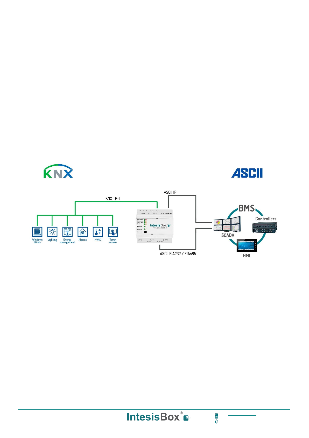
This document describes the integration of KNX installations into ASCII serial (EIA232 or EIA485) or ASCII IP compatible
devices and systems using the IntesisBox ASCII Server – KNX gateway.
The aim of this integration is to make accessible KNX system signals and resources from any system capable to be
programmed to read and write simple text messages through EIA232 or EIA485 serial port or Ethernet TCP/IP port (for
example Extron, LiteTouch systems).
The gateway acts as a KNX device in its KNX interface, reading/writing points of other KNX device(s), and offering this
point's values of KNX device(s) through its ASCII interface using simple ASCII messages.
Configuration is carried out using the configuration software IntesisBox® MAPS.
This document assumes that the user is familiar with ASCII and KNX technologies and their technical terms.
Figure 1.1 Integration of KNX into ASCII IP or ASCII Serial control and monitring systems
ASCII EIA232 / EIA485
Page 6

IntesisBox® ASCII Server – KNX User Manual r1.0 EN
© Intesis Software S.L.U. - All rights reserved
IntesisBox is a registered trademark of Intesis Software SLU
6/20
email: info@intesisbox.com
web: www.intesisbox.com
phone: +34 938047134
1.2 Functionality
From the KNX system point of view, after the start-up process, the gateway reads the points configured to be read at
the start and remains listening for changes of value of group addresses associated with internal data points. Any of
these changes, when detected, are immediately updated in memory and become available to be read by the ASCII
system in any moment.
From the ASCII system point of view, after the start up process of the gateway, IntesisBox waits for any query (ASCII
messages requesting readings of points or ASCII messages requesting writings of points) and acts according to the
message received. See ASCII interface section for details about this ASCII messages.
Each KNX group address from the KNX is associated to an ASCII, with this, all the configured points of the KNX are
seen as a single ASCII point.
When a new value is read from KNX group address, the new value is updated in the gateway's memory and made
accessible at ASCII Server interface.
1.3 Gateway’s capacity
IntesisBox capacity is listed below:
Element
600
version
3000
version
Notes
KNX groups
600
3000
Maximum number of different KNX group
addresses that can be defined.
KNX associations
1200
6000
Maximum number of KNX associtations
supported.
Number of ASCII Registers
600
3000
Maximum number of points that can be defined in
the virtual ASCII Server device inside the gateway
ASCII link layers supported
Serial (EIA485/EIA485)
TCP/IP
Communication with ASCII client with simple
messages through a TCP/IP or serial connection
Page 7

IntesisBox® ASCII Server – KNX User Manual r1.0 EN
© Intesis Software S.L.U. - All rights reserved
IntesisBox is a registered trademark of Intesis Software SLU
7/20
email: info@intesisbox.com
web: www.intesisbox.com
phone: +34 938047134
2 KNX System
In this section, a common description for all IntesisBox KNX series gateways is given, from the point of view of KNX
system which is called from now on internal system The Modbus system is also called from now on external system.
2.1 Description
IntesisBox KNX connects directly to the KNX TP-1 (EIB) bus and behaves as one more devices into the KNX system,
with the same configuration and operational characteristics as other KNX devices.
Internally, the circuit part connected to the KNX bus is opto-isolated from the rest of the electronics.
IntesisBox-KNX receives, manages and sends all the telegrams related to its configuration to the KNX bus.
On receiving telegrams of KNX Groups associated to internal datapoints, the corresponding messages are sent to the
external system (Modbus) to maintain both systems synchronised in every moment.
When a change in a signal of the external system is detected, a telegram is sent to the KNX bus (of the associated KNX
group) to maintain both systems synchronised in every moment.
The status of the KNX bus is checked continuously and, if a bus drops down is detected, due to a failure in the bus
power supply for example, when the KNX bus is restored again, IntesisBox will retransmit the status of all the KNX
groups marked as "T" Transmit. Also, the Updates of the groups marked as "U" Update will be performed. The behaviour
of each individual point into IntesisBox is determined by the flags configured for the point. See details in section 4.
2.2 Points definition
Every internal datapoint to define has the following KNX properties:
Property
Description
Description
Descriptive information about the Communication Object or Signal.
Signal
Signal's Description. Only for informative purposes, allows identifying the signal
comfortably.
DPT
It is the KNX data type used to code the signal's value. It will depend on the type of
signal associated in the external system in every case. In some integrations, it is
selectable, in others it is fixed due to the intrinsic characteristics of the signal.
Group
It is the KNX group to which the point is associated. It is also the group to which the
read (R), write (W), transmit (T) and update (U) flags are applied. Is the sending group.
Listening
addresses
They are the addresses that will actuate on the point, apart of the main Group address.
R
Read. If this flag is activated, read telegrams of this group address will be accepted.
Ri
Read. It this flag is activated, the object will be read on initialization.
W
Write. If this flag is activated, write telegrams of this group address will be accepted.
T
Transmit. If this flag is activated, when the point's value changes, due to a change in
the external system, a write telegram of the group address will be sent to the KNX bus.
U
Update. If this flag is activated, on IntesisBox start-up or after a KNX bus reset detection,
objects will be updated from KNX.
Active
If activated, the point will be active in IntesisBox, if not, the behaviour will be as if the
point is not defined. This allows deactivating points without the need of delete them for
possible future use.
These properties are common for all IntesisBox KNX series gateways. Although each integration may have specific
properties according to the type of signals of the external system.
Page 8

IntesisBox® ASCII Server – KNX User Manual r1.0 EN
© Intesis Software S.L.U. - All rights reserved
IntesisBox is a registered trademark of Intesis Software SLU
8/20
email: info@intesisbox.com
web: www.intesisbox.com
phone: +34 938047134
3 ASCII interface
This section describes the ASCII interface of the IntesisBox, its configuration and functionality.
3.1 Description
The gateway can be connected to any ASCII enabled device using its EIA232 interface (DB9 connector DTE), EIA485
interface or TCP/IP (Ethernet connector) and offers through this interface the possibility of supervision and control of its
internal KNX addresses using simple ASCII messages.
On receiving messages corresponding to write commands in its ASCII interface, the gateway sends the corresponding
write command message to the associated KNX group.
When a new value for a point is received from KNX, the corresponding ASCII message indicating the new value will be
sent through the ASCII interface, but only if the point is configured for sending this "spontaneous messages", if it is not
configured to do so, then the new value will be available to be polled in any moment from the ASCII enabled device
connected to this ASCII interface. This behaviour of sending or not through the ASCII interface the new values received
from KNX is configurable individually per point in the gateway.
3.2 ASCII Serial
Serial communication for the ASCII communication can be configured to match the ASCII master device.
Only the RX, TX and GND lines of the EIA232 connector are used (TX/RX+ and TX/RX- for EIA485).
3.3 ASCII TCP
The TCP port to use can be configured (by default 5000 is used).
The IP address, subnet mask and default router address to use by IntesisBox can be also configured.
3.4 Address Map
The ASCII address map is fully configurable; any point in the IntesisBox can be freely configured with the desired internal
register address. Check the configuration tool manual for more information.
3.5 Points definition
Every point defined in the gateway has the following ASCII features associated to it, which can be configured:
Feature
Description
Signal
Signal or point description. Only for information purposes at user level.
ASCII string
Defines the ASCII string that will be used to access this register
• Max length: 32 characters
Page 9

IntesisBox® ASCII Server – KNX User Manual r1.0 EN
© Intesis Software S.L.U. - All rights reserved
IntesisBox is a registered trademark of Intesis Software SLU
9/20
email: info@intesisbox.com
web: www.intesisbox.com
phone: +34 938047134
Read/Write
Defines the current function (read, write or both) to be used from the ASCII side with this
register. It can’t be configured as it is directly set when selecting the current KNX flags
applying to the communication object.
Function
Read
Write
Read/Write
KNX
communication
object flags
R
T
R T
W
U
W U
Ri U
W Ri U
R W Ri T U
R W T U
W T
Spontaneous
Determines if any change of value for the point received from KNX will generate a
spontaneous ASCII message to send through the ASCII interface informing about the new
value.
A/D
Defines the current variable type for this register from the ASCII side. It can’t be configured as
it is directly set when selecting the current KNX flags applying to the communication object
Type
Analog
Digital
KNX
communication
object
Communication
objects > 1bit
1bit
communication
objects
Page 10

IntesisBox® ASCII Server – KNX User Manual r1.0 EN
© Intesis Software S.L.U. - All rights reserved
IntesisBox is a registered trademark of Intesis Software SLU
10/20
email: info@intesisbox.com
web: www.intesisbox.com
phone: +34 938047134
3.6 ASCII messages
Communication from the ASCII side is carried out thanks to simple ASCII messages. Note that these messages can be
configured from the configuration tool to match the ASCII master device.
The ASCII messages used to read/write points into the gateway through this interface have the following format
• Message to read a point's value:
ASCII_String?\r
Where:
Characters
Description
ASCII_String
String indicating the point's address inside the gateway
?
Character use to indicate that this is a reading message
(configurable from the configuration tool)
\r
Carriage return character (HEX 0x0D, DEC 13)
• Message to write a point's value:
ASCII_String=vv\r
Where:
Characters
Description
ASCII_String
String indicating the point's address inside the gateway
=
Character use to indicate that this is a reading message
(configurable from the configuration tool)
vv
Current point’s value
\r
Carriage return character (HEX 0x0D, DEC 13)
• Message informing about a point's value (sent spontaneously by the gateway when receiving a change
from KNX or sent by the gateway in response to a previous poll for the point):
ASCII_String=vv\r
Where:
Characters
Description
ASCII_String
String indicating the point's address inside the gateway
=
Character use to indicate where point’s data starts
vv
Current point’s value
\r
Carriage return character (HEX 0x0D, DEC 13)
Page 11

IntesisBox® ASCII Server – KNX User Manual r1.0 EN
© Intesis Software S.L.U. - All rights reserved
IntesisBox is a registered trademark of Intesis Software SLU
11/20
email: info@intesisbox.com
web: www.intesisbox.com
phone: +34 938047134
4 Connections
Find below information regarding the IntesisBox connections available.
Power Supply
Must use NEC Class 2 or Limited Power Source (LPS) and SELV
rated power supply.
If using DC power supply:
Respect polarity applied of terminals (+) and (-). Be
sure the voltage applied is within the range admitted
(check table below). The power supply can be
connected to earth but only through the negative
terminal, never through the positive terminal.
If using AC power supply:
Make sure the voltage applied is of the value admitted
(24 Vac). Do not connect any of the terminals of the AC
power supply to earth, and make sure the same power
supply is not supplying any other device.
Ethernet / ASCII IP
Connect the cable coming from the IP network to the connector
ETH of the gateway. Use an Ethernet CAT5 cable. If
communicating through the LAN of the building, contact the
network administrator and make sure traffic on the port used is
allowed through all the LAN path (check the gateway user
manual for more information). With factory settings, after
powering up the gateway, DHCP will be enabled for 30 seconds.
After that time, if no IP is provided by a DHCP server, the default
IP 192.168.100.246 will be set.
PortA / KNX
Connect the KNX TP1 bus to connectors A3 (+) and A4 (-) of gateway’s PortA. Respect the polarity
PortB / ASCII Serial
Connect the EIA485 bus to connectors B1 (B+), B2 (A-) and B3 (SNGD) of gateway’s PortB. Respect the polarity.
Connect the serial cable EIA232 coming from the external serial device to the EIA232 connector of gateway’s PortB.
This is a DB9 male (DTE) connector in which only the lines TX, RX and GND are used. Respect the maximum distance
of 15 meters.
Note: Remember the characteristics of the standard EIA485 bus: maximum distance of 1200 meters, maximum
32 devices connected to the bus, and in each end of the bus it must be a termination resistor of 120 Ω. The port
includes a DIP-Switch for configuration of biasing circuit as well as termination:
SW1:
ON: 120 Ω termination active
OFF: 120 Ω termination inactive (default)
SW2-3:
ON: Polarization active
OFF: Polarization inactive
If the gateway is installed in one bus end make sure that termination is active.
Console Port
Connect a mini-type B USB cable from your computer to the gateway to allow communication between the Configuration
Software and the gateway. Remember that Ethernet connection is also allowed. Check the user manual for more
information.
Power Supply
Ethernet
ASCII IP
USB
storage
Console
Port
ASCII
EIA485
ASCII
EIA232
KNX
Page 12

IntesisBox® ASCII Server – KNX User Manual r1.0 EN
© Intesis Software S.L.U. - All rights reserved
IntesisBox is a registered trademark of Intesis Software SLU
12/20
email: info@intesisbox.com
web: www.intesisbox.com
phone: +34 938047134
USB
Connect a USB storage device (not a HDD) if required. Check the user manual for more information.
Ensure proper space for all connectors when mounted (see section 7).
4.1 Powering the device
A power supply working with any of the voltage range allowed is needed (check section 6). Once connected the RUN
led (Figure above) will turn on.
WARNING! In order to avoid earth loops that can damage the gateway and/or any other equipment connected to it, we
strongly recommend:
• The use of DC power supplies, floating or with the negative terminal connected to earth. Never use a DC
power supply with the positive terminal connected to earth.
• The use of AC power supplies only if they are floating and not powering any other device.
4.2 Connection to ASCII
4.2.1 ASCII TCP/IP
Connect the communication cable coming from the network hub or switch to the ETH port of IntesisBox. The cable to
be used shall be a straight Ethernet UTP/FTP CAT5 cable.
4.2.2 ASCII Serial
Connect the communication cable coming from the ASCII network to the port marked as Port B of IntesisBox. Connect
the EIA485 bus to connectors to connectors B1 (B+), B2 (A-) and B3 (SNGD) of gateway’s PortB. Respect the polarity.
Remember the characteristics of the standard EIA485 bus: maximum distance of 1200 meters, maximum 32 devices
connected to the bus, and in each end of the bus it must be a termination resistor of 120 Ω. Set port switch SW1 to ON
if gateway is installed on one bus end. SW2-3 will generally go OFF (no polarization), as polarization will typically be
provided in the ASCII Serial master device.
4.3 Connection to KNX
Connect the communication cable coming from the KNX bus to the PortA of IntesisBox.
In case there is no response from the KNX installation or KNX devices to the telegrams sent by the IntesisBox, check
that they are operative and reachable from the KNX installation used by IntesisBox.
Check as well if there is a line coupler that it is not filtering the telegrams from/to the IntesisBox.
4.4 Connection to the configuration tool
This action allows the user to have access to configuration and monitoring of the device (more information can be found
in the configuration tool User Manual). Two methods to connect to the PC can be used:
• Ethernet: Using the Ethernet port of IntesisBox.
• USB: Using the console port of IntesisBox, connect a USB cable from the console port to the PC.
Page 13

IntesisBox® ASCII Server – KNX User Manual r1.0 EN
© Intesis Software S.L.U. - All rights reserved
IntesisBox is a registered trademark of Intesis Software SLU
13/20
email: info@intesisbox.com
web: www.intesisbox.com
phone: +34 938047134
5 Set-up process and troubleshooting
5.1 Pre-requisites
It is necessary to have an ASCII IP client or ASCII Serial master operative and well connected to the corresponding
ASCII port of IntesisBox as well as the KNX devices connected to their corresponding ports as well.
Connectors, connection cables, PC to use the configuration tool and other auxiliary material, if needed, are not supplied
by Intesis Software SLU for this standard integration.
Items supplied by Intesis Software for this integration are:
• IntesisBox gateway.
• Mini-USB cable to connect to PC
• Link to download the configuration tool.
• Product documentation.
5.2 IntesisBox MAPS. Configuration & monitoring tool for IntesisBox ASCII series
5.2.1 Introduction
IntesisBox MAPS is a Windows® compatible software developed specifically to monitor and configure IntesisBox ASCII
series.
The installation procedure and main functions are explained in the IntesisBox MAPS User Manual for ASCII. This
document can be downloaded from the link indicated in the installation sheet supplied with the IntesisBox device or in
the product website at www.intesisbox.com
In this section, only the specific case of KNX to ASCII systems will be covered.
Please check the IntesisBox MAPS user manual for specific information about the different parameters and how to
configure them.
5.2.2 Connection
To configure the IntesisBox connection parameters press on the Connection button in the menu bar.
Figure 5.1 MAPS connection
Page 14

IntesisBox® ASCII Server – KNX User Manual r1.0 EN
© Intesis Software S.L.U. - All rights reserved
IntesisBox is a registered trademark of Intesis Software SLU
14/20
email: info@intesisbox.com
web: www.intesisbox.com
phone: +34 938047134
5.2.3 Configuration tab
Select the Configuration tab to configure the connection parameters. Three subsets of information are shown in this
window: General (Gateway general parameters), ASCII (ASCII interface configuration) and KNX (KNX TP-1 interface
configuration).
Figure 5.2 IntesisBox MAPS configuration tab
General parameters are explained in IntesisBox MAPS user manual for IntesisBox ASCII Server Series.
5.2.3.1 ASCII Configuration
Set the parameters for connection to ASCII device.
Figure 5.3 IntesisBox MAPS configuration tab for ASCII Server
Page 15

IntesisBox® ASCII Server – KNX User Manual r1.0 EN
© Intesis Software S.L.U. - All rights reserved
IntesisBox is a registered trademark of Intesis Software SLU
15/20
email: info@intesisbox.com
web: www.intesisbox.com
phone: +34 938047134
• Communication type: Select if ASCII communication will be through TCP/IP, serial (EIA232 or EIA485) or
both.
• Notification on ASCII Value: Gateway will allow sending spontaneous messages to the ASCII bus when a
change of value is received in the KNX side.
• Answer required for write commands: If enabled, the gateway will send back an OK message to the ASCII
master device.
• Define custom string commands: Define the special character to be used to read or write the internal gateway
datapoint.
• Port: TCP port to be used for the ASCII communication. By default, it is set to 5000.
• Keep Alive: Time of inactivity before sending a keep alive message.
o 0: Disabled
o 1…1440: Possible values expressed in minutes. By default, it is set to 10.
• Connection type: Physical connection, between EIA232 and EIA485 can be selected.
• Baud rate: Selectable from 1200, 2400, 4800, 9600, 19200, 38400, 56700 and 115200.
• Data type:
o Data Bits: 8
o Parity can be selected from: none, even, odd.
o Stop Bits:1 and 2
5.2.4 Signals
All available objects, Object Instances, its corresponding ASCII register and other main parmaters are listed in the
signals tab. More information on each parameter and how to configure it can be found in the IntesisBox MAPS user
manual for ASCII.
Figure 5.4 IntesisBox MAPS Signals tab
Page 16

IntesisBox® ASCII Server – KNX User Manual r1.0 EN
© Intesis Software S.L.U. - All rights reserved
IntesisBox is a registered trademark of Intesis Software SLU
16/20
email: info@intesisbox.com
web: www.intesisbox.com
phone: +34 938047134
5.2.5 Sending the configuration to IntesisBox
When the configuration is finished, follow the next steps.
1.- Save the project (Menu option Project->Save) on your hard disk (more information in IntesisBox MAPS User
Manual).
2.- Go to tab ‘Receive / Send’ of MAPS, and in Send section, press Send button. IntesisBox will reboot
automatically once the new configuration is loaded.
Figure 5.5 IntesisBox MAPS Receive/Send tab
After any configuration change, do not forget to send the configuration file to the IntesisBox using the
Send button in the Receive / Send section.
5.2.6 Diagnostic
To help integrators in the commissioning tasks and troubleshooting, the Configuration Tool offers some specific tools
and viewers.
In order to start using the diagnostic tools, connection with the Gateway is required.
The Diagnostic section is composed by two main parts: Tools and Viewers.
• Tools
Use the tools section to check the current hardware status of the box, log communications into
compressed files to be sent to the support, change the Diagnostic panels’ view or send commands to
the gateway.
• Viewers
In order to check the current status, viewer for the Internal and External protocols are available. It is
also available a generic Console viewer for general information about communications and the gateway
status and finally a Signals Viewer to simulate the BMS behavior or to check the current values in the
system.
Page 17

IntesisBox® ASCII Server – KNX User Manual r1.0 EN
© Intesis Software S.L.U. - All rights reserved
IntesisBox is a registered trademark of Intesis Software SLU
17/20
email: info@intesisbox.com
web: www.intesisbox.com
phone: +34 938047134
Figure 5.6 Diagnostic
More information about the Diagnostic section can be found in the Configuraion Tool manual.
Page 18

IntesisBox® ASCII Server – KNX User Manual r1.0 EN
© Intesis Software S.L.U. - All rights reserved
IntesisBox is a registered trademark of Intesis Software SLU
18/20
email: info@intesisbox.com
web: www.intesisbox.com
phone: +34 938047134
5.3 Set-up procedure
1. Install IntesisBox MAPS on your laptop, use the setup program supplied for this and follow the instructions given by
the Installation wizard.
2. Install IntesisBox in the desired installation site. Installation can be on DIN rail or on a stable not vibrating surface
(DIN rail mounted inside a metallic industrial cabinet connected to ground is recommended).
3. If using, ASCII Serial, connect the communication cable coming from the EIA485 port or the EIA232 port of the
ASCII installation to the port marked as Port B of IntesisBox (More details in section 2).
If using, ASCII TCP/IP, connect the communication cable coming from the Ethernet port of the ASCII installation to
the port marked as Ethernet of IntesisBox (More details in section 2).
4. Connect the KNX communication cable coming from the KNX network to the port marked as Port A on IntesisBox
(More details in section 2).
5. Power up IntesisBox. The supply voltage can be 9 to 30 Vdc or just 24 Vac. Take care of the polarity of the supply
voltage applied.
WARNING! In order to avoid earth loops that can damage IntesisBox and/or any other equipment connected to
it, we strongly recommend:
• The use of DC power supplies, floating or with the negative terminal connected to earth. Never use a DC
power supply with the positive terminal connected to earth.
• The use of AC power supplies only if they are floating and not powering any other device.
6. If you want to connect using IP, connect the Ethernet cable from the laptop PC to the port marked as Ethernet of
IntesisBox (More details in section 2). Using a hub or switch may be required.
If you want to connect using USB, connect the Ethernet cable from the laptop PC to the port marked as USB of
IntesisBox (More details in section 2).
7. Open IntesisBox MAPS, create a new project selecting a template for IBOX-ASCII-KNX.
8. Modify the configuration as desired, save it and download the configuration file to IntesisBox as explained in the
IntesisBox MAPS user manual.
9. Visit the Diagnostic section, enable COMMS and check that there is communication activity, some TX frames and
some other RX frames. This means that the communication with the Centralized Controller and ASCII Master
devices is OK. In case there is no communication activity between IntesisBox and the Centralized Controller and/or
ASCII devices, check that those are operative: check the baud rate, the communication cable used to connect all
devices and any other communication parameter.
Figure 5.7 Enable COMMS
Page 19

IntesisBox® ASCII Server – KNX User Manual r1.0 EN
© Intesis Software S.L.U. - All rights reserved
IntesisBox is a registered trademark of Intesis Software SLU
19/20
email: info@intesisbox.com
web: www.intesisbox.com
phone: +34 938047134
6 Electrical & Mechanical Features
Enclosure
Plastic, type PC (UL 94 V-0)
Net dimensions (dxwxh): 90x88x56 mm
Recommended space for installation (dxwxh): 130x100x100mm
Color: Light Grey. RAL 7035
Battery
Size: Coin 20mm x 3.2mm
Capacity: 3V / 225mAh
Type: Manganese Dioxide Lithium
Mounting
Wall.
DIN rail EN60715 TH35.
Console Port
Mini Type-B USB 2.0 compliant
1500VDC isolation
Terminal Wiring
(for power supply and
low-voltage signals)
Per terminal: solid wires or stranded wires (twisted or with ferrule)
1 core: 0.5mm2… 2.5mm2
2 cores: 0.5mm2… 1.5mm2
3 cores: not permitted
USB port
Type-A USB 2.0 compliant
Only for USB flash storage device
(USB pen drive)
Power consumption limited to 150mA
(HDD connection not allowed)
Power
1 x Plug-in screw terminal block (3 poles)
9 to 36VDC +/-10%, Max.: 140mA.
24VAC +/-10% 50-60Hz, Max.: 127mA
Recommended: 24VDC
Push Button
Button A: Reserved for future use
Button B: Reserved for future use
Operation
Temperature
0°C to +60°C
Ethernet
1 x Ethernet 10/100 Mbps RJ45
2 x Ethernet LED: port link and activity
Operational
Humidity
5 to 95%, no condensation
Port A
1 x KNX TP-1 Plug-in screw terminal block orange (2 poles)
2500VDC isolation from other ports
KNX power consumption: 5mA
Voltage rating: 29VDC
1 x Plug-in screw terminal block green (2 poles)
Reserved for future use
Protection
IP20 (IEC60529)
LED
Indicators
10 x On board LED indicators
1 x Error LED
1 x Power LED
2 x Ethernet Link/Speed
2 x Port A TX/RX
2 x Port B TX/RX
1 x Button A indicator
1 x Button B indicator
Switch A
(SWA)
1 x DIP-Switch for PORT A configuration:
Reserved for future use
PORT B
1 x Serial EIA232 (SUB-D9 male connector)
Pinout from a DTE device
1500VDC isolation from other ports
(except PORT B: EIA485)
1 x Serial EIA485 Plug-in screw terminal block (3 poles)
A, B, SGND (Reference ground or shield)
1500VDC isolation from other ports
(except PORT B: EIA232)
Switch B
SWB)
1 x DIP-Switch for serial EIA485 configuration:
Position 1:
ON: 120 Ω termination active
Off: 120 Ω termination inactive (default)
Position 2-3:
ON: Polarization active
Off: Polarization inactive (default)
100 mm
Page 20

IntesisBox® ASCII Server – KNX User Manual r1.0 EN
© Intesis Software S.L.U. - All rights reserved
IntesisBox is a registered trademark of Intesis Software SLU
20/20
email: info@intesisbox.com
web: www.intesisbox.com
phone: +34 938047134
7 Dimensions
Recommended available space for its installation into a cabinet (wall or DIN rail mounting), with space enough for
external connections
100 mm (h)
100 mm (w)
130 mm (d)
56 mm (h)
88 mm (w)
90 mm (d)
 Loading...