

Page 1

Compatible with Digital Inverter & VRF lines
USER MANUAL
Issue date: 04/2019 r2.7 ENGLISH
Page 2

Intesis
TM
INMBSTOS001R000
User’s Manual r2.7 EN
© HMS Industrial Networks S.L.U. - All rights reserved
This information is subject to change without notice
URL https://www.intesis.com
2 / 28
Modbus RTU (EIA-485) Interface for Toshiba air
conditioners
Compatible with Digital Inverter & VRF lines
ORDER CODE
LEGACY ORDER CODE
INMBSTOS001R000
TO-RC-MBS-1
Page 3

Intesis
TM
INMBSTOS001R000
User’s Manual r2.7 EN
© HMS Industrial Networks S.L.U. - All rights reserved
This information is subject to change without notice
URL https://www.intesis.com
3 / 28
Important User Information
Disclaimer
The information in this document is for informational purposes only. Please inform HMS Industrial Networks
of any inaccuracies or omissions found in this document. HMS Industrial Networks disclaims any responsibility
or liability for any errors that may appear in this document.
HMS Industrial Networks reserves the right to modify its products in line with its policy of continuous product
development. The information in this document shall therefore not be construed as a commitment on the
part of HMS Industrial Networks and is subject to change without notice. HMS Industrial Networks makes no
commitment to update or keep current the information in this document.
The data, examples and illustrations found in this document are included for illustrative purposes and are only
intended to help improve understanding of the functionality and handling of the product. In view of the wide
range of possible applications of the product, and because of the many variables and requirements associated
with any particular implementation, HMS Industrial Networks cannot assume responsibility or liability for
actual use based on the data, examples or illustrations included in this document nor for any damages incurred
during installation of the product. Those responsible for the use of the product must acquire sufficient
knowledge in order to ensure that the product is used correctly in their specific application and that the
application meets all performance and safety requirements including any applicable laws, regulations, codes
and standards. Further, HMS Industrial Networks will under no circumstances assume liability or responsibility
for any problems that may arise as a result from the use of undocumented features or functional side effects
found outside the documented scope of the product. The effects caused by any direct or indirect use of such
aspects of the product are undefined and may include e.g. compatibility issues and stability issues.
Page 4

Intesis
TM
INMBSTOS001R000
User’s Manual r2.7 EN
© HMS Industrial Networks S.L.U. - All rights reserved
This information is subject to change without notice
URL https://www.intesis.com
4 / 28
INDEX
1. Presentation .......................................................................................................... 5
2. Connection ............................................................................................................ 6
2.1 Connect to the AC indoor unit ............................................................................... 6
2.2 Connection to the EIA-485 bus ............................................................................. 6
3. Quick Start Guide ................................................................................................... 7
4. Modbus Interface Specification ................................................................................ 8
4.1 Modbus physical layer.......................................................................................... 8
4.2 Modbus Registers ................................................................................................ 8
4.2.1 Control and status registers ........................................................................... 8
4.2.2 Configuration Registers................................................................................ 10
4.3 Modbus Registers for Advanced Functions ............................................................ 10
4.3.1 Advanced registers for Indoor Unit status ...................................................... 10
4.3.2 Advanced registers for Outdoor Unit Status on VRF-SMMSi Systems .................. 11
4.3.3 Advanced registers for Outdoor Unit Status on VRF-SHRM/SMMS Systems ...... 13
4.3.4 Advanced registers for Outdoor Unit Status on RAV Systems ............................ 14
4.3.5 Advanced registers for Indoor Unit Type and Refresh Time adjustment .............. 15
4.3.6 Considerations on Temperature Registers ...................................................... 16
4.4 DIP-switch Configuration Interface ...................................................................... 18
4.5 Implemented Functions ..................................................................................... 21
4.6 Device LED indicator ......................................................................................... 21
4.7 EIA-485 bus. Termination resistors and Fail-Safe Biasing mechanism ...................... 22
5. Electrical and Mechanical features .......................................................................... 23
6. List of supported AC Unit Types. ............................................................................ 24
7. Error Codes ......................................................................................................... 25
Page 5

Intesis
TM
INMBSTOS001R000
User’s Manual r2.7 EN
© HMS Industrial Networks S.L.U. - All rights reserved
This information is subject to change without notice
URL https://www.intesis.com
5 / 28
1. Presentation
The INMBSTOS001R000 interfaces allow a complete and natural
integration of Toshiba air conditioners into Modbus RTU (EIA-485)
networks.
Compatible with Digital Inverter & VRF lines.
Reduced dimensions. 93 x 53 x 58 mm
3.7” x 2.1” x 2.3”
• Quick and easy installation.
Mountable on DIN rail, wall, or even inside the indoor unit of AC.
• External power not required.
• Direct connection to Modbus RTU (EIA-485) networks. Up to 63 INMBSTOS001R000 devices
can be connected in the same network.
INMBSTOS001R000 is a Modbus slave device.
• Direct connection to the AC indoor unit. Up to 16 AC indoor units can be connected to
INMBSTOS001R000, controlling them as one (not individually).
• Configuration from both on-board DIP-switches and Modbus RTU.
• Total Control and Supervision.
• Real states of the AC unit's internal variables.
• Allows simultaneous use of the AC’s remote controls and Modbus RTU.
* Up to 63 Intesis devices can be installed in the same Modbus RTU bus. However, depending on the configured speed, the installation
of Modbus Repeaters may be required
• SCADA
• PLC
• DDC
• BMS
• HMI
• Controller
• etc
Up to 63
AC indoor
units*
Modbus RTU
EIA-485 network
Modbus RTU
Master
device
INMBSTOS001R000
INMBSTOS001R000
INMBSTOS001R000
Page 6
Intesis
TM
INMBSTOS001R000
User’s Manual r2.7 EN
© HMS Industrial Networks S.L.U. - All rights reserved
This information is subject to change without notice
URL https://www.intesis.com
6 / 28
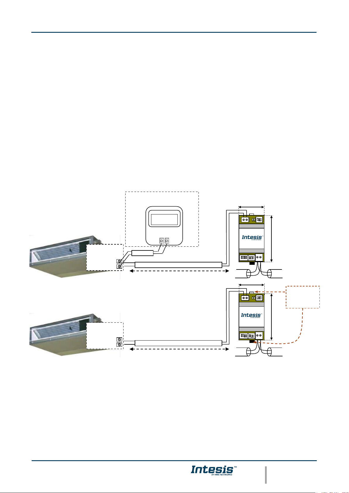
2. Connection
The interface comes with a plug-in terminal block of 2 poles to establish direct connection with
the AC indoor unit. It comes as well with a plug-in terminal block of 2 poles to establish direct
connection with the Modbus RTU EIA-485 network.
2.1 Connect to the AC indoor unit
The INMBSTOS001R000 connects directly to the Toshiba AB Bus, which is not provided within
the interface. The recommended connection’ methods are the following ones (details in Figure
2. 1):
• Wired remote control available.
• No remote control available
Maximum AB bus length is 500 m / 1,640.42 ft. The bus has no polarity sensitivity.
Important: If a wired remote controller of the AC manufacturer is connected in the same bus,
communication may shut down.
2.2 Connection to the EIA-485 bus
Connect the EIA-485 bus wires to the plug-in terminal block of INMBSTOS001R000 and keep
the polarity on this connection (A+ and B-). Make sure that the maximum distance to the bus is
1,200 meters (3,937 ft). Loop or star typologies are not allowed in the case of the EIA-485 bus.
A terminator resistor of 120Ω must be present at each end of the bus to avoid signal reflections.
The bus needs a fail-safe biasing mechanism (see section 4.7 for more details).
Max 500 m / 1,640.42 ft
Max 500 m / 1,640.42 ft
B
A
MODBUS RTU
EIA-485
Bus
EIA485
A+ B-
A B
AC Unit
B A
AC Indoor Unit
(It is not mandatory to have it in the network)
Internal
electronic
control board
Remote Controller
Toshiba
B
A
MODBUS RTU
EIA-485
Bus
EIA485
A+ B-
A B
AC Unit
AC Indoor Unit
Internal
electronic
control board
53 mm / 2.1”
90 mm / 3.5”
90 mm / 3.5”
53 mm / 2.1”
For wall mounting
extract the upper
and down staples
until you hear the
"click".
Figure 2. 1 INMBSTOS001R000 connection diagram
Page 7

Intesis
TM
INMBSTOS001R000
User’s Manual r2.7 EN
© HMS Industrial Networks S.L.U. - All rights reserved
This information is subject to change without notice
URL https://www.intesis.com
7 / 28
3. Quick Start Guide
1. Disconnect the air conditioning from the Mains Power.
2. Attach the interface next to the AC indoor unit (wall mounting) following the instructions
of the diagram below or install it inside the AC indoor unit (respect the safety
instructions given).
3. Connect the AB bus between the interface and the AC indoor unit following the
instructions of the diagram. Screw each bare cable end in the corresponding AB
terminals of each device.
4. Connect the EIA-485 bus to the connector EIA485 of the interface.
5. Close the AC indoor unit.
6. Check the DIP-Switch configuration of the Intesis interface and make sure it matches the
current installation’s parameters (see section 4.4).
By default, the interface is set to:
▪ Modbus Slave Address ➔ 1
▪ Modbus baud rate ➔ 9600 bps
These parameters can be modified from SW4 and SW3 DIP-Switches.
All other switch positions are set at low level (Off position ) by default.
NOTE: All changes on the DIP-Switch configuration require a system power cycle to be
applied.
7. Connect the AC system to Mains Power.
IMPORTANT: The Intesis interface requires to be connected to the AC unit (powered) to
start communicating.
ON
ON
SW3
SW4
Page 8

Intesis
TM
INMBSTOS001R000
User’s Manual r2.7 EN
© HMS Industrial Networks S.L.U. - All rights reserved
This information is subject to change without notice
URL https://www.intesis.com
8 / 28
4. Modbus Interface Specification
4.1 Modbus physical layer
INMBSTOS001R000 implements a Modbus RTU (Slave) interface, to be connected to an EIA-485
line. It performs 8N2 communication (8 data bits, no parity and 2 stop bit) with several
available baud rates (2400 bps, 4800 bps, 9600 bps -default-, 19200 bps, 38400 bps, 57600
bps, 76800 bps and 115200 bps). It also supports 8N1 communication (8 data bits, no parity
and 1 stop bit).
4.2 Modbus Registers
All registers are type “16-bit unsigned Holding Register” and they use the Modbus big endian
notation.
4.2.1 Control and status registers
Register Address
(protocol address)
Register Address
(PLC address)
R/W
Description
0
1
R/W
AC unit On/Off
▪ 0: Off
▪ 1: On
1
2
R/W
AC unit Mode 1
▪ 0: Auto
▪ 1: Heat
▪ 2: Dry
▪ 3: Fan
▪ 4: Cool
2
3
R/W
AC unit Fan Speed 1
▪ 0: Auto
▪ 1: Low
▪ 2: Mid
▪ 3: High
3
4
R/W
AC unit Vane Position 1
▪ 1: POS1 (Horizontal)
▪ 2: POS2 (Horizontal)
▪ 3: POS3 (Medium)
▪ 4: POS4 (Vertical)
▪ 5: POS5 (Vertical)
▪ 6: POS6
▪ 7: POS7
▪ 10: Swing
4
5
R/W
AC unit Temperature Setpoint
1,2,3
▪ -32768 (Initialization value)
▪ 16..32ºC (ºC/x10ºC)
▪ 61..90ºF
1
Available values will depend on the AC unit mode. Check the AC unit model functions in its user manual to know the possible values for
this register.
2
Magnitude for this register can be adjusted to Celsius x 1ºC, Celsius x 10ºC (default) or Fahrenheit. See section 4.3.6 for more
information.
3
It is not possible turn to x10 the value shown in Fahrenheit.
Page 9

Intesis
TM
INMBSTOS001R000
User’s Manual r2.7 EN
© HMS Industrial Networks S.L.U. - All rights reserved
This information is subject to change without notice
URL https://www.intesis.com
9 / 28
Register Address
(protocol address)
Register Address
(PLC address)
R/W
Description
5
6
R/W
AC unit Temperature reference
1,2,3
▪ -32768: Initial value. Value invalid, which
comes from the IU’s sensor. If the value that
is shown in register 22 (23 PLC) is valid, the
address is going to take this value.
▪ Ranges are specific from Manufacturer
(ºC/x10ºC/ºF)
6
7
R/W
Window Contact
▪ 0: Closed (Default)
▪ 1: Open
7
8
R/W
INMBSTOS001R000 Disablement 4
▪ 0: INMBSTOS001R000 enabled (Default)
▪ 1: INMBSTOS001R000 disabled
8
9
R/W
AC Remote Control Disablement 4
▪ 0: Remote Control enabled (Default)
▪ 1: Remote Control disabled
9
10
R/W
AC unit Operation Time 4
▪ 0..65535 (hours). Counts the time the AC
unit is in “On” state.
10
11
R
AC unit Alarm Status
▪ 0: No alarm condition
▪ 1: Alarm condition
11
12
R
Error Code 5
▪ 0: No Error active
▪ 65535 (-1): Error in the communication of
INMBSTOS001R000 with the AC indoor unit.
▪ Any other error present, see the table at the
end of this document.
22
23
R/W
Indoor unit´s ambient temperature from
external sensor (at Modbus side)
1,2,3,6
▪ -32768: Initialization value. No temperature
is being provided from an input sensor.
There’s no input sensor.
▪ Any other: (ºC/x10ºC/ºF)
23
24
R
AC Real temperature setpoint
1,2,3,6
▪ There’s no Virtual Temperature. The value
equals to the value of register 5 (6 PLC). The
value which is introduced by the user is the
one that the machine uses (the external
sensor is able to write directly over the
machine to do this operation).
▪ Ranges are specific from Manufacturer
(ºC/x10ºC/ºF)
97
98
R/W
Block Periodic Sendings
4,7,8
▪ 0: Non-blocked (Default value)
▪ 1: Blocked
4
This value is stored in non-volatile memory
5
See section 7 for possible error codes and their explanation
6
See section 4.3.6 for more information
7
If the register is configured as “0:Non-blocked”, all commands received from Modbus will be sent to the AC system. If “1: Blocked”,
commands from Modbus will only be sent to the AC system if they differ from the previous value.
8
This register applies to firmware version 2.3 onwards
Page 10

Intesis
TM
INMBSTOS001R000
User’s Manual r2.7 EN
© HMS Industrial Networks S.L.U. - All rights reserved
This information is subject to change without notice
URL https://www.intesis.com
10 / 28
4.2.2 Configuration Registers
Register Address
(protocol address)
Register Address
(PLC address)
R/W
Description
13
14
R/W
“Open Window” switch-off timeout 9
▪ 0..30 (minutes)
▪ Factory setting: 30 (minutes)
14
15
R
Modbus RTU baud-rate 10
▪ 2400bps
▪ 4800bps
▪ 9600bps (Default)
▪ 19200bps
▪ 38400bps
▪ 57600bps
▪ 76800bps
▪ 115200bps
15
16
R
Modbus Slave Address
▪ 1..63
21
22
R
Max number of fan speeds
49
50
R
Device ID: 0x1F00
50
51
R
Software version
While the initialization is ongoing, some Modbus registers indicate an undetermined value. Once
the normal operation starts, they acquire its corresponding value. It is important to keep in
mind that any change done during the initialization process will not have effect until it has been
finished.
4.3 Modbus Registers for Advanced Functions
4.3.1 Advanced registers for Indoor Unit status
These registers are only available when the indoor unit’s type selected on SW1 is different from
the default value. Please, check the Section 4.4 for more information.
NOTE: IU stands for Indoor Unit’s index
Register Address
(Protocol address)
Register Address
(PLC address)
R/W
Description
Priority
(IU – 1) * 25 + 4000
(IU – 1) * 25 + 4001
R
Indoor Unit exist
▪ 0: Doesn’t exist
▪ 1: Exist
0
(IU – 1) * 25 + 4001
(IU – 1) * 25 + 4002
R
Indoor Unit address
▪ MSB – OU address ; LSB – IU
address
0
(IU – 1) * 25 + 4002
(IU – 1) * 25 + 4003
R
Indoor Unit duty
▪ 0..15
1
(IU – 1) * 25 + 4003
(IU – 1) * 25 + 4004
R
Indoor Unit defrost
▪ 0: Off
▪ 1: On
1
9
Once window contact is open, a count-down to switch off the AC Unit will start from this configured value.
10
The range 38400bps-115200bps applies to firmware version 2.3 onwards
Page 11

Intesis
TM
INMBSTOS001R000
User’s Manual r2.7 EN
© HMS Industrial Networks S.L.U. - All rights reserved
This information is subject to change without notice
URL https://www.intesis.com
11 / 28
Register Address
(Protocol address)
Register Address
(PLC address)
R/W
Description
Priority
(IU – 1) * 25 + 4004
(IU – 1) * 25 + 4005
R
Indoor Unit filter alarm
▪ 0: No alarm
▪ 1: Alarm
1
(IU – 1) * 25 + 4005
(IU – 1) * 25 + 4006
R
Indoor Unit 11hermos ON.
▪ 0: Cool
▪ 1: Heat
1
(IU – 1) * 25 + 4010
(IU – 1) * 25 + 4011
R
Room temperature (During
Control)
▪ x1 ºC
2
(IU – 1) * 25 + 4011
(IU – 1) * 25 + 4012
R
Room temperature (Remote
Controller)
▪ x1 ºC
2
(IU – 1) * 25 + 4012
(IU – 1) * 25 + 4013
R
Indoor suction temperature (TA)
▪ x1 ºC
1
(IU – 1) * 25 + 4013
(IU – 1) * 25 + 4014
R
Indoor fan coil temperature (TCJ)
▪ x1 ºC
1
(IU – 1) * 25 + 4014
(IU – 1) * 25 + 4015
R
Indoor fan coil temperature
(TC2)
▪ x1 ºC
1
(IU – 1) * 25 + 4015
(IU – 1) * 25 + 4016
R
Indoor fan coil temperature
(TC1)
▪ x1 ºC
1
(IU – 1) * 25 + 4016
(IU – 1) * 25 + 4017
R
Indoor discharge temperature
(TF)
▪ x1 ºC
▪ Only for VRF systems
0
(IU – 1) * 25 + 4017
(IU – 1) * 25 + 4018
R
Revolutions indoor fan
▪ RPS
▪ Only for RAV systems
0
(IU – 1) * 25 + 4018
(IU – 1) * 25 + 4019
R
Indoor PMV opening
▪ x1, x10 Pulses
▪ Only for VRF systems
1
(IU – 1) * 25 + 4019
(IU – 1) * 25 + 4020
R
Running hours indoor fan
▪ x100 hours
▪ Only for RAV systems
0
(IU – 1) * 25 + 4020
(IU – 1) * 25 + 4021
R
Time filtersign
▪ Hours
▪ Only for RAV systems
0
(IU – 1) * 25 + 4021
(IU – 1) * 25 + 4022
R
Estimated supply air temperature
▪ x1 ºC
▪ Only for RAV systems
0
4.3.2 Advanced registers for Outdoor Unit Status on VRF-SMMSi Systems
These registers are only available when the indoor unit’s type selected on SW1 is different from
the default value. Please, check section 4.4 for more information.
Register Address
(protocol address)
Register Address
(PLC address)
R/W
Description
Priority
4200
4201
R
Outdoor Unit duty
▪ 15
1
Page 12

Intesis
TM
INMBSTOS001R000
User’s Manual r2.7 EN
© HMS Industrial Networks S.L.U. - All rights reserved
This information is subject to change without notice
URL https://www.intesis.com
12 / 28
Register Address
(protocol address)
Register Address
(PLC address)
R/W
Description
Priority
4210
4211
R
High-pressure sensor detention
pressure (Pd)
▪ X100 Mpa
2
4211
4212
R
Low-pressure sensor detention
pressure (Ps)
▪ X100 Mpa
2
4212
4213
R
Compressor 1 discharge
temperature (Td1)
▪ x1 ºC
2
4213
4214
R
Compressor 2 discharge
temperature (Td2)
▪ x1 ºC
2
4214
4215
R
Compressor 3 discharge
temperature (Td3)
▪ x1 ºC
2
4215
4216
R
Suction temperature (TS)
▪ x1 ºC
2
4216
4217
R
Outdoor fan coil temperature 1
(TE1)
▪ x1 ºC
2
4217
4218
R
Outdoor fan coil temperature 2
(TE2)
▪ x1 ºC
1
4218
4219
R
Temperature at liquid side (TL)
▪ x1 ºC
2
4219
4220
R
Outside ambient temperature
(TO)
▪ x1 ºC
1
4220
4221
R
PMV1 + 2 opening
▪ x1 Pulse
2
4221
4222
R
PMV4 opening
▪ x1 Pulse
2
4222
4223
R
Compressor 1 current (I1)
▪ x10 A
1
4223
4224
R
Compressor 2 current (I2)
▪ x10 A
2
4224
4225
R
Compressor 3 current (I3)
▪ x10 A
2
4225
4226
R
Outdoor fan current (Ifan)
▪ x10 A
2
4226
4227
R
Compressor 1 revolutions
▪ x10 RPS
2
4227
4228
R
Compressor 2 revolutions
▪ x10 RPS
2
4228
4229
R
Compressor 3 revolutions
▪ x10 RPS
2
4229
4230
R
Outdoor fan mode
▪ x1 mode
2
4230
4231
R
Compressor IPDU 1 heat sink
temperature
▪ x1 ºC
2
4231
4232
R
Compressor IPDU 2 heat sink
temperature
▪ x1 ºC
2
4232
4233
R
Compressor IPDU 3 heat sink
temperature
▪ x1 ºC
2
Page 13

Intesis
TM
INMBSTOS001R000
User’s Manual r2.7 EN
© HMS Industrial Networks S.L.U. - All rights reserved
This information is subject to change without notice
URL https://www.intesis.com
13 / 28
Register Address
(protocol address)
Register Address
(PLC address)
R/W
Description
Priority
4233
4234
R
Outdoor fan IPDU heat sink
temperature
▪ x1 ºC
2
4234
4235
R
Heating/cooling recovery
controlled ∗5
▪ 0: Normal
▪ 1: Recovery controlled
2
4235
4236
R
Pressure release ∗5
▪ 0: Normal
▪ 1: Recovery controlled
2
4236
4237
R
Discharge temperature release ∗5
▪ 0: Normal
▪ 1: Recovery controlled
2
4237
4238
R
Follower unit release (U2/U2/U4
outdoor units) ∗5
▪ 0: Normal
▪ 1: Recovery controlled
2
4238
4239
R
Outdoor unit horsepower
▪ x1 HP
0
4.3.3 Advanced registers for Outdoor Unit Status on VRF-SHRM/SMMS
Systems
These registers are only available when the indoor unit’s type selected on SW1 is different from
the default value. Please, check section 4.4 for more information
Register Address
(protocol address)
Register Address
(PLC address)
R/W
Description
Priority
4200
4201
R
Outdoor Unit duty
▪ 15
1
4210
4211
R
Td1-Compressor 1 Discharge
Temp.
▪ x1 ºC
2
4211
4212
R
Td2-Compressor 2 Discharge
Temp.
▪ x1 ºC
2
4212
4213
R
Pd – High Pressure Sensor
▪ Mpa
2
4213
4214
R
Ps – Low Pressure Sensor
▪ Mpa
2
4214
4215
R
TS – Suction Temp.
▪ x1 ºC
2
4215
4216
R
TE – Outdoor Heat Exchanger
Temp.
▪ x1 ºC
2
4216
4217
R
TL – Liquid Temp.
▪ x1 ºC
2
4217
4218
R
TO – Outside ambient
temperature
▪ x1 ºC
1
4218
4219
R
TU – Low Pressure Saturated
Temp.
▪ x1 ºC
2
Page 14

Intesis
TM
INMBSTOS001R000
User’s Manual r2.7 EN
© HMS Industrial Networks S.L.U. - All rights reserved
This information is subject to change without notice
URL https://www.intesis.com
14 / 28
Register Address
(protocol address)
Register Address
(PLC address)
R/W
Description
Priority
4219
4220
R
Compressor 1 Current
▪ A
1
4220
4211
R
Compressor 2 Current
▪ A
2
4221
4222
R
PMV1 + 2 Opening
▪ 0..100
2
4223
4224
R
Compressor 1, 2
▪ 0: Off
▪ 1: On
2
4224
4225
R
Outdoor Fan Mode
▪ 0..31
2
4225
4226
R
Outdoor Unit Size
▪ HP
2
4.3.4 Advanced registers for Outdoor Unit Status on RAV Systems
These registers are only available when the indoor unit’s type selected on SW1 is different from
the default value. Please, check section 4.4 for more information
Register Address
(protocol address)
Register Address
(PLC address)
R/W
Description
Priority
4400
4401
R
Outdoor Unit duty
▪ 0..15
1
4410
4411
R
TE temperature (evaporator)
▪ x1 ºC
2
4411
4412
R
TO temperature outdoor
▪ x1 ºC
1
4412
4413
R
Compressor discharge
temperature
▪ x1 ºC
2
4413
4414
R
Suction temperature TS
▪ x1 ºC
2
4414
4415
R
Temperature thyristor THS
▪ x1 ºC
0
4415
4416
R
Compressor current
▪ A
1
4416
4417
R
Temperature at liquid side TL
▪ x1 ºC
2
4417
4418
R
Compressor revolutions
▪ RPS
2
4418
4419
R
Revolutions lowest Fan
▪ RPS
0
4419
4420
R
Revolutions upper Fan
▪ RPS
0
4420
4221
R
Running hours compressor
▪ x100 hours
2
Page 15

Intesis
TM
INMBSTOS001R000
User’s Manual r2.7 EN
© HMS Industrial Networks S.L.U. - All rights reserved
This information is subject to change without notice
URL https://www.intesis.com
15 / 28
4.3.5 Advanced registers for Indoor Unit Type and Refresh Time adjustment
Register Addr
(protocol address)
Register Addr
(PLC address)
R/W
Description
Priority
4450
4451
R
Indoor Unit Type
▪ 0: Not defined (extra signals
disabled)
▪ 1: RAV
▪ 2: VRF (SMMSi)
▪ 3: VRF (SHRM/SMMS)
0
4451
4452
R/W
Refresh Time Adjust
▪ 1..4
-
Refresh Time Adjust
This parameter indicates the cadence when reading priority signals.
Priorities are defined as follows and can’t be modified:
0: Update on start-up
1: High priority
2: Low priority
The higher the value, the fastest the priority signals are going to update.
The cadence is defined by:
1: One high priority signal and one low priority signal’s poll.
2: Two high priority signals and one low priority signal’s poll.
3: Three high priority signals and one low priority signal’s poll.
4: Four high priority signals and one low priority signal’s poll.
Page 16

Intesis
TM
INMBSTOS001R000
User’s Manual r2.7 EN
© HMS Industrial Networks S.L.U. - All rights reserved
This information is subject to change without notice
URL https://www.intesis.com
16 / 28
4.3.6 Considerations on Temperature Registers
• AC unit temperature setpoint (R/W)
(register 4 – in Protocol address / register 5 – in PLC address):
This is the adjustable temperature setpoint value that must be required by the user.
This register can be read (Modbus function 3 or 4) or written (Modbus functions 6 or 16).
A remote controller connected to the Toshiba indoor unit will report the same
temperature setpoint value as this register.
• AC unit temperature reference (R)
(register 5 – in Protocol address / register 6 – in PLC address):
This register reports the temperature that is currently used by the Toshiba indoor unit as
the reference of its own control loop.
If the value on the register 22 is valid (different from 0x8000), it will report the value
from this register. If not, it will show the indoor unit reference temperature.
It is a read-only register (Modbus functions 3 or 4).
Depending on the mode selected, the register shows a different value:
Heat Mode:
Temperature reference = Ambient temperature +0.5ºC
Dry Mode / Fan Mode / Cool mode:
Temperature reference = Ambient temperature -0.5ºC
When the mode changes from Heat to anyone else, or from anyone else to Heat, the
register updates the value using the intervals +0.5ºC/-0.5ºC
• AC unit external temperature reference (Modbus) (R/W)
(register 22 – in Protocol address / register 23 – in PLC address):
This register reports the temperature from an external sensor in the Modbus side. If
valid value is received, the Modbus register will indicate a 0x8000 value.
This register can be read (Modbus function 3 or 4) or written (Modbus functions 6 or 16).
• AC Real temperature setpoint (R)
(register 23 – In Protocol address / register 24 – in PLC address):
This register will show the same value as in register 4 (protocol address). The reference
temperature from the remote controller is sent directly to the AC unit to be applied in the
control loop.
It is a read-only register (Modbus functions 3 or 4).
Moreover, notice that temperature’s values of all these four registers are expressed according to
the temperature´s format configured through its onboard DIP-Switches (See “4.4 -
Page 17

Intesis
TM
INMBSTOS001R000
User’s Manual r2.7 EN
© HMS Industrial Networks S.L.U. - All rights reserved
This information is subject to change without notice
URL https://www.intesis.com
17 / 28
DIP-switch Configuration Interface”). These following formats are possible:
• Celsius value: Value in Modbus register is the temperature value in Celsius (i.e. a
value “22” in the Modbus register must be interpreted as 22ºC)
• Decicelsius value: Value in Modbus register is the temperature value in
decicelsius (i.e. a value “220” in the Modbus register must be interpreted as
22.0ºC)
• Fahrenheit value: Value in Modbus register is the temperature value in
Fahrenheit (i.e. a value “72” in the Modbus register must be interpreted as 72 ºF
(~22ºC).
Page 18

Intesis
TM
INMBSTOS001R000
User’s Manual r2.7 EN
© HMS Industrial Networks S.L.U. - All rights reserved
This information is subject to change without notice
URL https://www.intesis.com
18 / 28
4.4 DIP-switch Configuration Interface
All the configuration values on INMBSTOS001R000 can be written and read from Modbus
interface. Otherwise, some of them can also be setup from its on-board DIP-switch interface.
The device has DIP-switches SW1, SW3 and SW4 on the following locations:
The following tables apply to the interface´s configuration through DIP-switches:
SW1 – AC indoor unit’s features
SW1-P1..2
Description
Indoor Unit type not defined (Default value)
Machine type: VRF-SMMSi
Machine type: RAV
Machine type: VRF-SMMS/SHRM
Not used (Default value)
Not used
Esclavo del bus A B (Valor por defecto)- Debe existir un mando Toshiba configurado como Header
en el bus AB
Slave of bus A B (Default value) – A Toshiba Controller must be present in the AB bus, configured
as Header.
Maestro del bus A B - No es necesario un mando Toshiba en bus AB. Si lo hay, debe ser configurado
como Follower.
Master of bus A B –Toshiba Remote Controller is not necessary to have it in the bus AB. If it exists, it
must be configured as Follower.
Table 4.1 SW1: AC indoor unit´s features
SW3
SW4
EIA485
A+ B-
A B
AC Unit
SW1
SW1
SW4
ON
1 2 3 4
ON
SW3
1 2 3 4
1 2 3 4 5 6 7 8
ON
ON
ON
ON
ON
ON
ON
ON
ON
Page 19

Intesis
TM
INMBSTOS001R000
User’s Manual r2.7 EN
© HMS Industrial Networks S.L.U. - All rights reserved
This information is subject to change without notice
URL https://www.intesis.com
19 / 28
SW3/SW4 – Baud rate configuration
SW3-P7..8
SW4-P3
Description
2400bps
4800bps
9600bps (Default value)
19200bps
38400bps
57600bps
76800bps
115200bps
Table 4.2 SW3-SW4: Modbus baud rate
SW4 – Degrees/Decidegrees (x10), temperature magnitude (ºC/ºF) and EIA-485 termination
resistor.
Table 4.3 SW4: Temperature and termination resistor configuration
SW4-P1..2-4
Description
Temperature values in Modbus register are represented in degrees (x1) (Default value)
Temperature values in Modbus register are represented in Decidegrees (x10)
Temperature values in Modbus register are represented in Celsius degrees (Default value)
Temperature values in Modbus register are represented in Fahrenheit degrees
EIA-485 bus without termination resistor (Default value)
Internal termination resistor of 120Ω connected to EIA-485 bus
ON
ON
ON
ON
ON
ON
ON
ON
ON
ON
ON
ON
ON
ON
ON
ON
ON
ON
ON
ON
ON
ON
Page 20

Intesis
TM
INMBSTOS001R000
User’s Manual r2.7 EN
© HMS Industrial Networks S.L.U. - All rights reserved
This information is subject to change without notice
URL https://www.intesis.com
20 / 28
SW3 – Modbus Slave address
Table 4.4 SW3: Modbus slave address
Add SW3-P1..6
Add
SW3-P1..6
Add
SW3-P1..6
Add
SW3-P1..6
Add
SW3-P1..6
0
13
26
39
52
1
14
27
40
53
2
15
28
41
54
3
16
29
42
55
4
17
30
43
56
5
18
31
44
57
6
19
32
45
58
7
20
33
46
59
8
21
34
47
60
9
22
35
48
61
10
23
36
49
62
11 24 37 50 63
12 25 38 51
ON
ON
ON
ON
ON
ON
ON
ON
ON
ON
ON
ON
ON
ON
ON
ON
ON
ON
ON
ON
ON
ON
ON
ON
ON
ON
ON
ON
ON
ON
ON
ON
ON
ON
ON
ON
ON
ON
ON
ON
ON
ON
ON
ON
ON
ON
ON
ON
ON
ON
ON
ON
ON
ON
ON
ON
ON
ON
ON
ON
ON
ON
ON
ON
Page 21

Intesis
TM
INMBSTOS001R000
User’s Manual r2.7 EN
© HMS Industrial Networks S.L.U. - All rights reserved
This information is subject to change without notice
URL https://www.intesis.com
21 / 28
4.5 Implemented Functions
INMBSTOS001R000 implements the following standard Modbus functions:
▪ 3: Read Holding Registers
▪ 4: Read Input Registers
▪ 6: Write Single Register
▪ 16: Write Multiple Registers (Despite this function is allowed, the interface does not
allow to write operations on more than 1 register with the same request, this means that
length field should be always be 1 when this function is being used in case of writing)
4.6 Device LED indicator
The device includes two LED indicators to show all the possible operational states. In the
following table there are written the indicators which can be performed and their meaning.
L1 (green LED)
Device status
LED indication
ON / OFF Period
Description
During not normal
operation
LED blinking
500ms ON / 500ms OFF
Communication error
During normal
operation
LED flashing
100ms ON / 1900ms OFF
Normal operation (configured and
working properly)
L2 (red LED)
Device status
LED indication
ON / OFF Period
Description
During not normal
operation
LED Pulse
3sec ON / --- OFF
Under voltage
L1 (green LED) & L2 (red LED)
Device status
LED indication
ON / OFF Period
Description
During normal
operation
LED Pulse
5sec ON / --- OFF
Device Start-up
During not normal
operation
LED alternatively
blinking
500ms ON / 500ms OFF
EEPROM failure
Page 22

Intesis
TM
INMBSTOS001R000
User’s Manual r2.7 EN
© HMS Industrial Networks S.L.U. - All rights reserved
This information is subject to change without notice
URL https://www.intesis.com
22 / 28
4.7 EIA-485 bus. Termination resistors and Fail-Safe Biasing
mechanism
EIA-485 bus requires a 120Ω terminator resistor at each end of the bus to avoid signal
reflections.
In order to prevent fail status detected by the receivers, which are “listening” the bus, when all
the transmitters’ outputs are in three-state (high impedance), it is also required a fail-safe
biasing mechanism. This mechanism provides a safe status (a correct voltage level) in the bus
when all the transmitters’ outputs are in three-state. This mechanism must be supplied by the
Modbus Master.
The INMBSTOS001R000 device includes an on-board terminator resistor of 120Ω that can be
connected to the EIA-485 bus by using DIP-switch SW4.
Some Modbus RTU EIA-485 Master devices can provide also internal 120Ω terminator resistor
and/or fail-safe biasing mechanism (Check the technical documentation of the Master device
connected to the EIA-485 network in each case).
Page 23

Intesis
TM
INMBSTOS001R000
User’s Manual r2.7 EN
© HMS Industrial Networks S.L.U. - All rights reserved
This information is subject to change without notice
URL https://www.intesis.com
23 / 28
5. Electrical and Mechanical features
Enclosure
Plastic, type PC (UL 94 V-0)
Net dimensions (dxwxh):
93 x 53 x 58 mm / 3.7” x 2.1” x 2.3”
Color: Light Grey. RAL 7035
Operation
Temperature
0ºC to +60ºC
Weight
85 g.
Stock
Temperature
-20ºC to +85ºC
Mounting
Wall
DIN rail EN60715 TH35.
Operational
Humidity
<95% RH, non-condensing
Terminal Wiring
(for low-voltage
signals)
For terminal: solid wires or stranded wires
(twisted or with ferrule)
1 core: 0.5mm2… 2.5mm2
2 cores: 0.5mm2… 1.5mm2
3 cores: not permitted
Stock Humidity
<95% RH, non-condensing
Modbus RTU
port
1 x Serial EIA485 Plug-in screw terminal
block (2 poles):
A, B
Compatible with Modbus RTU EIA-485
networks
Isolation voltage
1500 VDC
AC unit port
1 x AB bus Plug-in screw terminal block
(2 poles):
A, B
Compatible with Toshiba networks
Isolation
resistance
1000 MΩ
Switch 1
(SW1)
1 x DIP-Switch for AC features
Protection
IP20 (IEC60529)
Switch 3
(SW3)
1 x DIP-Switch for Modbus RTU settings
LED indicators
2 x Onboard LED - Operational
status
Switch 4
(SW4)
1 x DIP-Switch for extra functions
EIA-485
Port
AC Unit
connection
DIP
Switch SW3
DIP
Switch SW1
LED
Indicators
DIP
Switch SW4
Page 24

Intesis
TM
INMBSTOS001R000
User’s Manual r2.7 EN
© HMS Industrial Networks S.L.U. - All rights reserved
This information is subject to change without notice
URL https://www.intesis.com
24 / 28
6. List of supported AC Unit Types.
A list of Toshiba indoor unit model references compatible with INMBSTOS001R000 and their
available features can be found in:
https://www.intesis.com/docs/compatibilities/inxxxtos001rx00_compatibility
Page 25

Intesis
TM
INMBSTOS001R000
User’s Manual r2.7 EN
© HMS Industrial Networks S.L.U. - All rights reserved
This information is subject to change without notice
URL https://www.intesis.com
25 / 28
7. Error Codes
Error
Code
Decimal
Error
Code
Hex
Error in
Remote
Controller
Error category
Error Description
0 0 N/A
INMBSTOS001R000
No active error
33
21
C01
Central Controller
Issues
Duplicated setting of control address
34
22
C02
Central control number of units mis-matched
35
23
C03
Incorrect wiring of central control
36
24
C04
Incorrect connection of central control
System Controller fault, error in transmitting
comms signal, i/door or o/door unit not
working, wiring fault
37
25
C05
38
26
C06
System Controller fault, error in receiving
comms signal, i/door or o/door unit not
working, wiring fault, CN1 not connected
correctly
44
2C
C12
Batch alarm by local controller
48
30
C16
Transmission error from adaptor to unit
49
31
C17
Reception error to adaptor from unit
50
32
C18
Duplicate central address in adaptor
51
33
C19
Duplicate adaptor address
52
34
C20
Mix of PAC & GHP type units on adaptor
53
35
C21
Memory fault in adaptor
54
36
C22
Incorrect address setting in adaptor
55
37
C23
Host terminal software failure
56
38
C24
Host terminal hardware failure
57
39
C25
Host terminal processing failure
58
3A
C26
Host terminal communication failure
60
3C
C28
Reception error of S-DDC from host terminal
61
3D
C29
Initialization failure of S-DDC
63
3F
C31
Configuration change detected by adaptor
65
41
E01
Addressing and
Communication
Problems
Remote control detecting error from indoor unit,
Address not set/Auto address failed. Check
interconnecting wiring etc. Re-address system.
66
42
E02
Remote detecting error from indoor unit,
67
43
E03
Indoor unit detecting error from remote,
68
44
E04
Indoor seeing error from outdoor. Qty of i/d
units connected are less than qty set. Check; all
i/d units are ON, reset turn off all units wait
5min power up
69
45
E05
Indoor unit detecting error from outdoor unit,
Error in sending comms signal
70
46
E06
Outdoor unit detecting error from indoor unit,
Error in receiving comms signal
71
47
E07
Outdoor unit detecting error from indoor unit,
Error in sending comms signal
72
48
E08
Incorrect setting indoor/controller, Indoor
address duplicated
73
49
E09
Incorrect setting indoor/controller, Remote
address duplicated or IR wireless controller not
disabled
74
4A
E10
Indoor unit detecting error from ‘option’ plug,
Error in sending comms signal
75
4B
E11
Indoor unit detecting error from ‘option’ plug,
Error in receiving comms signal
76
4C
E12
Auto addressing failed, Auto address connector
CN100 shorted during auto addressing
77
4D
E13
Indoor unit failed to send signal to remote
Page 26

Intesis
TM
INMBSTOS001R000
User’s Manual r2.7 EN
© HMS Industrial Networks S.L.U. - All rights reserved
This information is subject to change without notice
URL https://www.intesis.com
26 / 28
controller
78
4E
E14
Setting Failure, Duplication of master indoor
units
79
4F
E15
Auto addressing failed, Number of indoor units
connected are less than number set
80
50
E16
Auto addressing failed, Number of indoor units
connected are more than number set
81
51
E17
Addressing and
Communication
Problems
Group control wiring error, Main indoor unit not
sending signal for sub indoor units
82
52
E18
Group control wiring error, Main indoor unit not
receiving signal for sub indoor units
83
53
E19
Outdoor header units quantity error
84
54
E20
Auto addressing failed, No indoor units
connected
87
57
E23
Sending error in communication between
outdoor units
88
58
E24
Auto addressing failed, Error on sub outdoor
unit
89
59
E25
Auto addressing failed, Error on outdoor unit
address setting
90
5A
E26
Auto addressing failed, Quantity of main and
sub outdoor units do not correspond to the
number set on main outdoor unit P.C.B.
92
5C
E28
Follower outdoor unit error
93
5D
E29
Auto addressing failed, Sub outdoor unit not
receiving comms for main outdoor unit
95
5F
E31
Between units, Comms failure with MDC, does
E31 remain after power is re-instated? If so
replace PCB. & power PCB
97
61
F01
Sensor Faults
Indoor Heat Exch inlet temp sensor failure (E1)
98
62
F02
Indoor Heat Exch freeze temp sensor failure
(E2)
99
63
F03
Indoor Heat Exch outlet temp sensor failure
(E3)
100
64
F04
Outdoor Discharge temp sensor failure (TD) or
(DISCH1)
101
65
F05
Outdoor Discharge temp sensor failure
(DISCH2)
102
66
F06
Outdoor Heat Exch temp sensor failure (C1) or
(EXG1)
103
67
F07
Outdoor Heat Exch temp sensor failure (C2) or
(EXL1)
104
68
F08
Outdoor Air temp sensor failure (TO)
106
6A
F10
Indoor inlet temp sensor failure
107
6B
F11
Indoor outlet temp sensor failure
108
6C
F12
Outdoor Intake sensor failure (TS)
109
6D
F13
GHP – Cooling water temperature sensor failure
111
6F
F15
Outdoor temp. sensor misconnection (TE1,TL)
112
70
F16
Outdoor High pressure sensor failure
113
71
F17
GHP - Cooling water temperature sensor fault
114
72
F18
GHP - Exhaust gas temperature sensor fault
116
74
F20
GHP Clutch coil temperature fault
119
77
F23
Outdoor Heat Exch temp sensor failure (EXG2)
120
78
F24
Outdoor Heat Exch temp sensor failure (EXL2)
125
7D
F29
Indoor EEPROM error
126
7E
F30
Clock Function (RTC) fault
127
7F
F31
Outdoor EEPROM error
129
81
H01
Compressor Issues
Compressor Fault, Over current (Comp1)
130
82
H02
Compressor Fault, Locked rota current detected
(Comp1)
131
83
H03
Compressor Fault, No current detected (Comp1)
Page 27

Intesis
TM
INMBSTOS001R000
User’s Manual r2.7 EN
© HMS Industrial Networks S.L.U. - All rights reserved
This information is subject to change without notice
URL https://www.intesis.com
27 / 28
132
84
H04
Comp-1 case thermo operation
133
85
H05
Compressor Fault, Discharge temp not detected
(Comp1)
134
86
H06
Compressor Fault, Low Pressure trip
135
87
H07
Compressor Fault, Low oil level
136
88
H08
Compressor Fault, Oil sensor Fault (Comp1)
139
8B
H11
Compressor Fault, Over current (Comp2)
140
8C
H12
Compressor Fault, Locked rota current detected
(Comp2)
141
8D
H13
Compressor Fault, No current detected (Comp2)
142
8E
H14
Comp-2 case thermo operation
143
8F
H15
Compressor Fault, Discharge temp not detected
(Comp2)
144
90
H16
Oil level detection circuit error / Magnet switch
error /
Overcurrent relay error
149
95
H21
Compressor Fault, Over current (Comp3)
150
96
H22
Compressor Fault, Locked rota current detected
(c.3)
151
97
H23
Compressor Issues
Compressor Fault, No current detected (Comp3)
153
99
H25
Compressor Fault, Discharge temp not detected
(Comp3)
155
9B
H27
Compressor Fault, Oil sensor fault (Comp2)
156
9C
H28
Compressor Fault. Oil sensor (connection
failure)
159
9F
H31
Compressor Fault. IPM trip (IMP current on
temperature)
193
C1
L01
Incorrect Settings
Setting Error, Indoor unit group setting error
194
C2
L02
Setting Error, Indoor/outdoor unit type/model
miss-matched
195
C3
L03
Duplication of main indoor unit address in group
control
196
C4
L04
Duplication of outdoor unit system address
197
C5
L05
2 or more controllers have been set as 'priority'
in one system - shown on controllers set as
'priority'
198
C6
L06
2 or more controllers have been set as 'priority'
in one system - shown on controllers not set as
'priority'
199
C7
L07
Group wiring connected on and individual indoor
unit
200
C8
L08
Indoor unit address/group not set
201
C9
L09
Indoor unit capacity code not set
202
CA
L10
Outdoor unit capacity code not set
203
CB
L11
Group control wiring incorrect
205
CD
L13
Indoor unit type setting error, capacity
207
CF
L15
Indoor unit paring fault
208
D0
L16
Water heat exch. unit setting failure
209
D1
L17
Miss-match of outdoor unit with different
refrigerant
210
D2
L18
4-way valve failure
211
D3
L19
Water heat exch. unit duplicated address
212
D4
L20
Duplicated central control addresses
213
D5
L21
Gas type setup failure
220
DC
L28
Maximum number of outdoor units exceeded
221
DD
L29
No. of IPDU error
222
DE
L30
Auxiliary interlock in indoor unit
223
DF
L31
IC error
225
E1
P01
Indoor Unit
Problems
Indoor unit fault, Fan motor thermal overload
226
E2
P02
Outdoor unit fault, Compressor motor thermal
overload, over or under voltage
Page 28

Intesis
TM
INMBSTOS001R000
User’s Manual r2.7 EN
© HMS Industrial Networks S.L.U. - All rights reserved
This information is subject to change without notice
URL https://www.intesis.com
28 / 28
227
E3
P03
Outdoor unit fault, Compressor discharge
temperature too high (Comp1) over 111 ºC.
Low on ref gas, exp. valve, pipework damage.
228
E4
P04
Outdoor unit fault, High pressure trip
229
E5
P05
Outdoor unit fault, Open phase on power
supply. Check power on each phase, inverter
PCB, control PCB
231
E7
P07
Heat sink overheat error
233
E9
P09
Indoor unit fault, Ceiling panel incorrectly wired
234
EA
P10
Indoor unit fault, Condensate float switch
opened
235
EB
P11
GHP - Water Heat exch. low temp (frost
protection) fault
236
EC
P12
Indoor unit fault, Fan DC motor fault
237
ED
P13
Outdoor liquid back detection error
238
EE
P14
Input from leak detector (If fitted)
239
EF
P15
Refrigerant loss, high discharge temp and EEV
wide open and low compressor current draw.
240
F0
P16
Outdoor unit fault, Open phase on compressor
power supply
241
F1
P17
Outdoor unit fault, Compressor discharge
temperature too high (Comp2) over 111ºC. Low
on ref gas, exp. valve, pipework damage.
242
F2
P18
Outdoor unit fault, By-pass valve failure
243
F3
P19
Outdoor unit fault, 4 way valve failure, i/door
temp rises in cooling or fills in heating. Check
wiring, coil, PCB output, valve operation.
244
F4
P20
Ref gas, high temp/pressure fault, heat exch.
temp high C2, 55-60 ºC, cooling over-load,
sensor fault.
246
F6
P22
Outdoor unit fan motor fault, fan blade
jammed, check connections, does fan turn
freely, motor resistance 30-40ohm on each
pair, no fan fault, yes PCB fault.
250
FA
P26
Outdoor unit fault, Compressor overcurrent check winding resistance, Inverter failure check internal resistance term HIC + & - to
UVW 200-300Kohm or more
252
FC
P29
Outdoor unit fault, Inverter circuit fault - Motorcurrent Detection Circuit (MDC) fault, check
comp windings, sensors C1 & TS, if ok possible
PCB failure.
253
FD
P30
Indoor unit fault, System controller detected
fault on sub indoor unit
255
FF
P31
Simultaneous operation multi control fault,
Group controller fault
65535
(-1)
N/A
INMBSTOS001R000
Error in the communication of
INMBSTOS001R000 with the AC unit
In case to detect an error code not listed, contact your closest Toshiba technical support
service.
 Loading...