

Page 1

Compatible with NASA commercial air conditioners commercialized by Samsung
USER MANUAL
Issue date: 04/2019 r1.2 ENGLISH
Page 2
IntesisTM INMBSSAM001R100 (Samsung NASA)
User’s Manual r1.2 EN
© HMS Industrial Networks S.L.U - All rights reserved
This information is subject to change without notice
URL https://www.intesis.com
2 / 21
Compatible with NASA commercial air conditioners commercialized by Samsung
ORDER CODE
LEGACY ORDER CODE
INMBSSAM001R100
SM-RC2-MBS-1
Page 3

IntesisTM INMBSSAM001R100 (Samsung NASA)
User’s Manual r1.2 EN
© HMS Industrial Networks S.L.U - All rights reserved
This information is subject to change without notice
URL https://www.intesis.com
3 / 21
Important User Information
Disclaimer
The information in this document is for informational purposes only. Please inform HMS Industrial Networks
of any inaccuracies or omissions found in this document. HMS Industrial Networks disclaims any responsibility
or liability for any errors that may appear in this document.
HMS Industrial Networks reserves the right to modify its products in line with its policy of continuous product
development. The information in this document shall therefore not be construed as a commitment on the
part of HMS Industrial Networks and is subject to change without notice. HMS Industrial Networks makes no
commitment to update or keep current the information in this document.
The data, examples and illustrations found in this document are included for illustrative purposes and are only
intended to help improve understanding of the functionality and handling of the product. In view of the wide
range of possible applications of the product, and because of the many variables and requirements associated
with any particular implementation, HMS Industrial Networks cannot assume responsibility or liability for
actual use based on the data, examples or illustrations included in this document nor for any damages incurred
during installation of the product. Those responsible for the use of the product must acquire sufficient
knowledge in order to ensure that the product is used correctly in their specific application and that the
application meets all performance and safety requirements including any applicable laws, regulations, codes
and standards. Further, HMS Industrial Networks will under no circumstances assume liability or responsibility
for any problems that may arise as a result from the use of undocumented features or functional side effects
found outside the documented scope of the product. The effects caused by any direct or indirect use of such
aspects of the product are undefined and may include e.g. compatibility issues and stability issues.
Page 4

IntesisTM INMBSSAM001R100 (Samsung NASA)
User’s Manual r1.2 EN
© HMS Industrial Networks S.L.U - All rights reserved
This information is subject to change without notice
URL https://www.intesis.com
4 / 21
INDEX
1. Presentation .......................................................................................................... 5
2. Connection ............................................................................................................ 6
2.1 Connect to the AC indoor unit ............................................................................... 6
2.2 Connection to the EIA-485 bus ............................................................................. 7
3. Quick Start Guide ................................................................................................... 7
4. Modbus Interface Specification ................................................................................ 8
4.1 Modbus physical layer.......................................................................................... 8
4.2 Modbus Registers ................................................................................................ 8
4.2.1 Control and status registers ........................................................................... 8
4.2.2 Configuration Registers................................................................................ 10
4.2.3 Considerations on Temperature Registers ...................................................... 11
4.3 DIP-switch Configuration Interface ...................................................................... 13
4.4 Implemented Functions ..................................................................................... 16
4.5 Device LED indicator ......................................................................................... 16
4.6 EIA-485 bus. Termination resistors and Fail-Safe Biasing mechanism ...................... 17
5. Electrical and Mechanical features .......................................................................... 18
6. List of supported AC Unit Types. ............................................................................ 19
7. Error Codes ......................................................................................................... 20
Page 5
IntesisTM INMBSSAM001R100 (Samsung NASA)
User’s Manual r1.2 EN
© HMS Industrial Networks S.L.U - All rights reserved
This information is subject to change without notice
URL https://www.intesis.com
5 / 21
1. Presentation
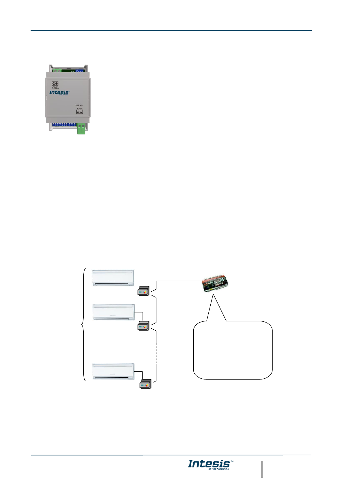
The INMBSSAM001R100 interfaces allow a complete and natural
integration of Samsung NASA air conditioners into Modbus RTU (EIA-
485) networks.
Reduced dimensions. 93 x 53 x 58 mm / 3.7” x 2.1” x 2.3”
Quick and easy installation.
Mountable on DIN rail, wall, or even inside the indoor unit of AC.
• External power not required.
• Direct connection to Modbus RTU (EIA-485) networks. Up to 63 INMBSSAM001R100 devices
can be connected in the same network.
INMBSSAM001R100 is a Modbus slave device.
• Direct connection to the AC unit.
• Configuration from both on-board DIP-switches and Modbus RTU.
• Total Control and Supervision.
• Real states of the AC unit's internal variables.
• Allows simultaneous use of the AC’s remote controls and Modbus RTU.
* Up to 63 Intesis devices can be installed in the same Modbus RTU bus. However, depending on the configured speed, the installation
of Modbus Repeaters may be required
• SCADA
• PLC
• DDC
• BMS
• HMI
• Controller
• etc
Up to 63
AC indoor
units*
Modbus RTU
EIA-485 network
Modbus RTU
Master
device
INMBSSAM001R100
INMBSSAM001R100
INMBSSAM001R100
Page 6
IntesisTM INMBSSAM001R100 (Samsung NASA)
User’s Manual r1.2 EN
© HMS Industrial Networks S.L.U - All rights reserved
This information is subject to change without notice
URL https://www.intesis.com
6 / 21
2. Connection
The interface comes with 1 plug-in terminal block of 2 poles to establish direct connection with
the AC indoor unit. It comes as well with a plug-in terminal block of 2 poles to establish direct
connection with the Modbus RTU EIA-485 network.
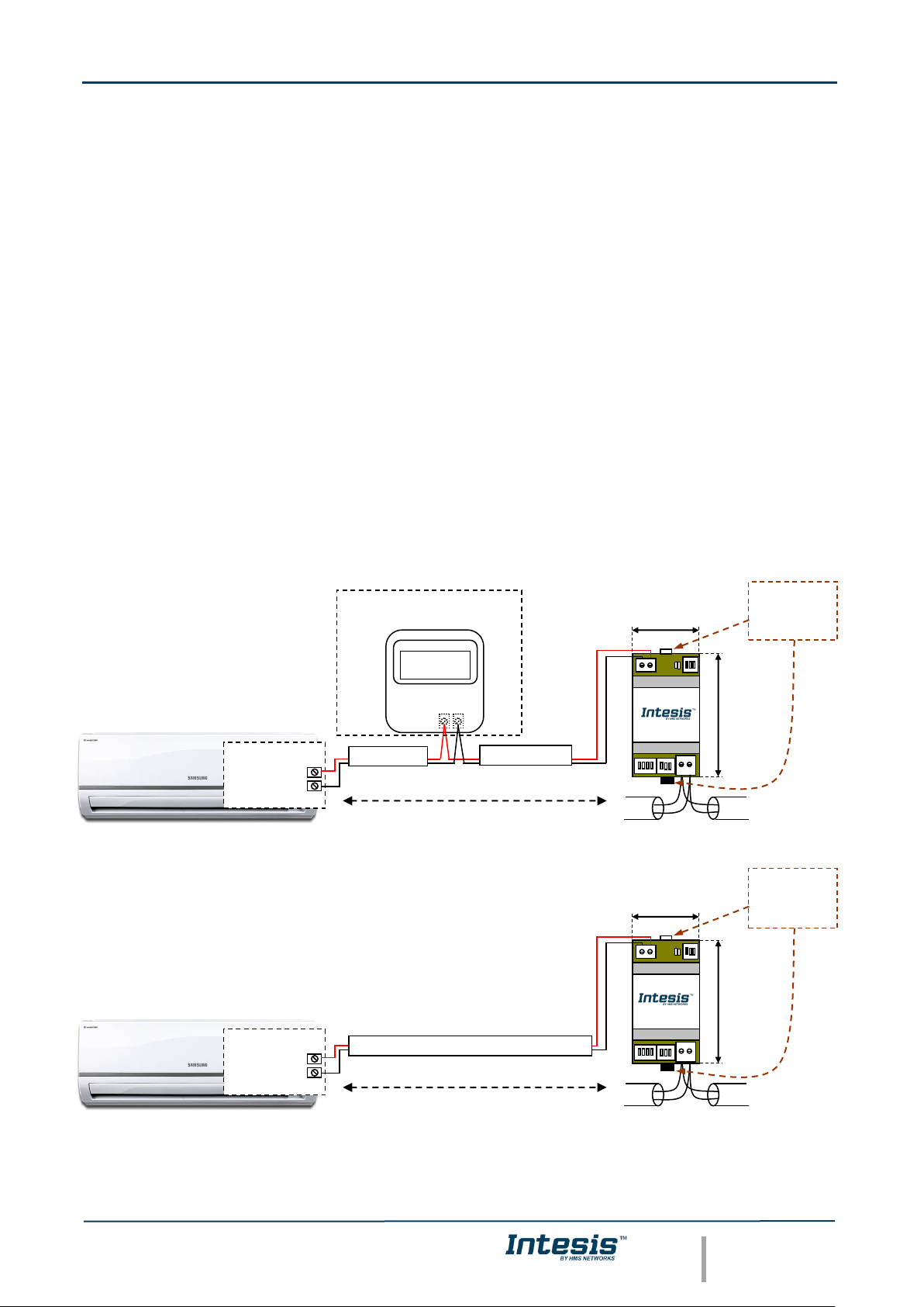
2.1 Connect to the AC indoor unit
The INMBSSAM001R100 connects directly to the Samsung Remote Controller Bus (F3F4
Connector). Depending on which controllers are available, the recommended connection’
methods are the following ones (details in Figure 2. 1):
• Wired remote control available. Connect the gateway as Slave in parallel with the
wired Remote Controllers (Remote Controller acts as Master).
• No remote control available Connect the gateway directly to the F3F4 bus of the
indoor unit as Master. There’s no Samsung Remote Controller.
Maximum F3F4 bus length is 100 m (328.08 ft). The communication F3F4 bus has polarity
sensitivity.
Important: If a wired remote controller of the AC manufacturer is connected in the same bus,
communication may shut down.
Figure 2. 1 INMBSSAM001R100 connection diagram
90 mm / 3.5”
MODBUS RTU
EIA-485
Bus
EIA485
A+ B-
F3 F4
AC Unit
53 mm / 2.1”
For wall mounting
extract the upper
and down staples
until you hear the
"click".
F4 F3
AC Indoor Unit
(It is not mandatory to have it in the network)
Connection to F3F4 bus.
Two wire cable.
Remote Controller
Samsung
F4
F3
Internal
Electronic
control board
Max. 100 m / 328.08 ft
90 mm / 3.5”
MODBUS RTU
EIA-485
Bus
EIA485
A+ B-
F3 F4
AC Unit
53 mm / 2.1”
For wall mounting
extract the upper
and down staples
until you hear the
"click".
AC Indoor Unit
Connection to F3F4 bus.
Two wire cable.
F4
F3
Internal
Electronic
control board
Max. 100 m / 328.08 ft
Page 7

IntesisTM INMBSSAM001R100 (Samsung NASA)
User’s Manual r1.2 EN
© HMS Industrial Networks S.L.U - All rights reserved
This information is subject to change without notice
URL https://www.intesis.com
7 / 21
2.2 Connection to the EIA-485 bus
Connect the EIA-485 bus wires to the plug-in terminal block (the one labeled as EIA485) of
INMBSSAM001R100 and keep the polarity on this connection (A+ and B-). Make sure that the
maximum distance to the bus is 1,200 meters (3,937 ft). Loop or star typologies are not
allowed in the case of the EIA-485 bus. A terminator resistor of 120Ω must be present at each
end of the bus to avoid signal reflections. The bus needs a fail-safe biasing mechanism (see
section 4.6 for more details).
3. Quick Start Guide
1. Disconnect the air conditioning from the Mains Power.
2. Attach the interface next to the AC indoor unit (wall mounting) following the instructions
of the diagram below or install it inside the AC indoor unit (respect the safety
instructions given).
3. Connect the F3F4 bus between the interface and the AC indoor unit following the
instructions of the diagram. Screw each bare cable end in the corresponding F3F4
terminals.
4. Connect the EIA-485 bus to the connector EIA485 of the interface.
5. Close the AC indoor unit.
6. Check the DIP-Switch configuration of the Intesis interface and make sure it matches the
current installation’s parameters (see section 4.3).
By default, the interface is set to:
▪ Modbus Slave Address ➔ 1
▪ Modbus baud rate ➔ 9600 bps
These parameters can be modified from SW4 and SW3 DIP-Switches.
All other switch positions are set at low level (Off position ) by default.
NOTE: All changes on the DIP-Switch configuration require a system power cycle to be
applied.
7. Connect the AC system to Mains Power.
IMPORTANT: The Intesis interface requires to be connected to the AC unit (powered) to
start communicating.
ON
ON
SW3
SW4
Page 8

IntesisTM INMBSSAM001R100 (Samsung NASA)
User’s Manual r1.2 EN
© HMS Industrial Networks S.L.U - All rights reserved
This information is subject to change without notice
URL https://www.intesis.com
8 / 21
4. Modbus Interface Specification
4.1 Modbus physical layer
INMBSSAM001R100 implements a Modbus RTU (Slave) interface, to be connected to an EIA485 line. It performs 8N2 communication (8 data bits, no parity and 2 stop bit) with several
available baud rates (2400 bps, 4800 bps, 9600 bps -default-, 19200 bps, 38400 bps, 57600
bps, 76800 bps and 115200 bps). It also supports 8N1 communication (8 data bits, no parity
and 1 stop bit).
4.2 Modbus Registers
All registers are type “16-bit unsigned Holding Register” and they use the Modbus big endian
notation.
4.2.1 Control and status registers
Register Address
(protocol address)
Register Address
(PLC address)
R/W
Description
0
1
R/W
AC unit On/Off
▪ 0: Off
▪ 1: On
1
2
R/W
AC unit Mode 1
▪ 0: Auto
▪ 1: Heat
▪ 2: Dry
▪ 3: Fan
▪ 4: Cool
2
3
R/W
AC unit Fan Speed 1
▪ 0: Auto
▪ 1: Low
▪ 2: Mid
▪ 3: High
▪ 4: Turbo
3
4
R/W
AC unit Vane UD Position 1
▪ 0: Swing Off (Auto)
▪ 10: Swing On
4
5
R/W
AC unit Temperature setpoint
1,2,3
▪ -32768 (Initialization value)
▪ Cool: 18..30ºC (ºC/x10ºC) / 65..86ºF
▪ Heat: 16..30ºC (ºC/x10ºC) / 63..86ºF
5
6
R
AC unit Temperature reference
1,2,3
▪ -32768 (Initialization value)
▪ -41..38ºC (ºC/x10ºC)
▪ -106..212ºF
6
7
R/W
Window Contact
▪ 0: Closed (Default)
▪ 1: Open
1
Available values will depend on the AC unit mode. Check the AC unit model functions in its user manual to know the possible values for
this register.
2
Magnitude for this register can be adjusted to Celsius x 1ºC, Celsius x 10ºC (default) or Fahrenheit. See section 4.2.3 for more
information.
3
It is not possible turn to x10 the value shown in Fahrenheit.
Page 9

IntesisTM INMBSSAM001R100 (Samsung NASA)
User’s Manual r1.2 EN
© HMS Industrial Networks S.L.U - All rights reserved
This information is subject to change without notice
URL https://www.intesis.com
9 / 21
Register Address
(protocol address)
Register Address
(PLC address)
R/W
Description
7
8
R/W
INMBSSAM001R100 Disablement 4
▪ 0: INMBSSAM001R100 enabled (Default)
▪ 1: INMBSSAM001R100 disabled
8
9
R/W
AC Remote Control Disablement 4
▪ 0: Remote Controller enabled (Default)
▪ 1: Remote Controller disabled
9
10
R/W
AC unit Operation Time 4
▪ 0..65535 (hours). Counts the time the AC
unit is in “On” state.
10
11
R
AC unit Alarm Status
▪ 0: No alarm condition
▪ 1: Alarm condition
11
12
R
Error Code 5
▪ 0: No error present
▪ 65535(-1 if it is read as signed value): Error
in the communication of INMBSSAM001R100
with the AC indoor unit.
▪ Any other error present, see the table at the
end of this document.
22
23
R/W
Indoor unit´s ambient temperature from
external sensor (at Modbus side)
1,2,3,6
▪ -32768: (Initialization value). No
temperature is being provided from an
external sensor.
▪ Any other: (ºC/x10ºC/ºF)
23
24
R
AC Real temperature setpoint
1,2,3,6
▪ When no external temperature is provided,
this read-only register will have the same
value as register 5 (PLC addressing). In all
cases, it will show the current setpoint in the
indoor unit.
▪ 16..31ºC (ºC/x10ºC)
▪ 60..92ºF
26
27
R/W
AC unit Left/Right Vane Position
▪ 0: Swing Off (Auto)
▪ 10: Swing On
40
41
R
Window contact ON/OFF Disablement
▪ 0: Window contact is not disabling option
On/Off at this moment (Default value)
▪ 1: Window contact is disabling option On/Off
at this moment
44
45
R
Filter status
▪ 0: OK
▪ 1: Filter cleaning
66
67
R
Return path Temperature
1,2,3
▪ -32768 (Initialization value)
▪ Ranges determined by the Manufacturer of
the AC indoor unit: (ºC/x10ºC/ºF)
97
98
R/W
Block Periodic Sendings
4,7,8
▪ 0: Non-blocked (Default value)
▪ 1: Blocked
4
This value is stored in non-volatile memory
5
See section 7 for possible error codes and their explanation
6
See section 4.2.3 for more information
7
If the register is configured as “0: Non-blocked”, all commands received from Modbus will be sent to the AC system. If “1: Blocked”,
commands from Modbus will only be sent to the AC system if they differ from the previous value (values sent on change).
8
This register applies to firmware version 0.1 onwards
Page 10

IntesisTM INMBSSAM001R100 (Samsung NASA)
User’s Manual r1.2 EN
© HMS Industrial Networks S.L.U - All rights reserved
This information is subject to change without notice
URL https://www.intesis.com
10 / 21
4.2.2 Configuration Registers
Register Address
(protocol address)
Register Address
(PLC address)
R/W
Description
13
14
R/W
“Open Window” switch-off timeout 9
▪ 0..30 (minutes)
▪ Factory setting: 30 (minutes)
14
15
R
Modbus RTU baud-rate
▪ 2400bps
▪ 4800bps
▪ 9600bps (Default)
▪ 19200bps
▪ 38400bps
▪ 57600bps
▪ 76800bps
▪ 115200bps
15
16
R
Modbus Slave Address
▪ 1..63
43
44
W
Filter reset
▪ 1: Filter reset
49
50
R
Device ID: 0x2E00
50
51
R
Software version
67
68
R
Number of IUs connected
▪ Indicates the number of indoor units
connected to the same RC bus.
68
69
R/W
Internal IU address
▪ All indoor units connected in the RC bus are
listed in an Internal array in address
ascending order. This register indicates the
position in the array of the current indoor
unit status reported.
69
70
R
IU Address status reported
▪ Address of the indoor unit that reports the
status in case there is more than one
indoor unit connected in the RC bus.
99
100
W
Reset/Reboot device
▪ 1: Reset
9
Once window contact is open, a count-down to switch off the AC Unit will start from this configured value.
Page 11

IntesisTM INMBSSAM001R100 (Samsung NASA)
User’s Manual r1.2 EN
© HMS Industrial Networks S.L.U - All rights reserved
This information is subject to change without notice
URL https://www.intesis.com
11 / 21
4.2.3 Considerations on Temperature Registers
• AC unit temperature setpoint (R/W)
(register 4 – in Protocol address / register 5 – in PLC address):
This is the adjustable temperature setpoint value that must be required by the user. This
register can be read (Modbus function 3 or 4) or written (Modbus functions 6 or 16). A
remote controller connected to the Samsung indoor unit will report the same
temperature setpoint value as this register.
• AC unit temperature reference (R)
(register 5 – in Protocol address / register 6 – in PLC address):
This register reports the temperature that is currently used by the Samsung indoor unit
as the reference of its own control loop. Depending on the configuration of the indoor
unit, this value can be: the temperature reported by the sensor of the return path of the
Samsung indoor unit, the temperature provided by the sensor of its remote controller or
the temperature provided by Modbus (external temperature). It is a read-only register
(Modbus functions 3 or 4).
• AC unit external temperature reference (Modbus) (R/W)
(register 22 – in Protocol address / register 23 – in PLC address):
This register allows us to provide an external temperature’s sensor from the Modbus
side. If a valid value is written in this register, this will be sent to the Samsung Remote
Controller bus (RC). Notice that in order to apply this setting, the system shall be set so
that the Indoor Unit is configured to use the ambient temperature from the Remote
Controller as the reference of its own control loop.
Please, check Samsung’s User Manual or Samsung’s Installation Manual to see how the
reference temperature source can be changed from the own return path to the reference
temperature.
After the startup, the value for “external temperature’s reference” (register 22/23) has a
value -32768 (0x8000). This value means that no external temperature reference is
being provided through INMBSSAM001R100. In this scenario, the AC indoor unit will use
its own return path temperature sensor as reference for its control loop or the remote
controller’s one (if connected and configured to do so).
This register can be read (Modbus function 3 or 4) or written (Modbus functions 6 or 16)
• AC temperature Real setpoint (R)
(register 23 – In Protocol address / register 24 – in PLC address):
As it has been detailed on the previous point, the real temperature setpoint in the indoor
unit and the temperature setpoint requested from INMBSSAM001R100 might differ
(when a value in register 22/23 – “external temperature reference” is entered). This
register always informs about the current temperature setpoint which is being used by
the indoor unit – it is also includes the temperature setpoint that will be shown by an
additional remote controller from Samsung connected to the indoor unit, if it is present
on the system.
This register can be read (Modbus function 3 or 4)
Page 12

IntesisTM INMBSSAM001R100 (Samsung NASA)
User’s Manual r1.2 EN
© HMS Industrial Networks S.L.U - All rights reserved
This information is subject to change without notice
URL https://www.intesis.com
12 / 21
• Return path Temperature (R)
(register 66 – in Protocol address / register 67 – in PLC address):
This register shows the temperature value reported by the sensor of the own return path
of the Samsung indoor unit. It is a read-only register (Modbus functions 3 or 4).
Moreover, notice that temperature’s values of all these four registers are expressed according to
the temperature´s format configured through its onboard DIP-Switches (See section 4.3).
These following formats are possible:
• Celsius value: Value in Modbus register is the temperature value in Celsius (i.e. a
value “22” in the Modbus register must be interpreted as 22ºC).
• Decicelsius value: Value in Modbus register is the temperature value in
decicelsius (i.e. a value “220” in the Modbus register must be interpreted as
22.0ºC).
• Fahrenheit value: Value in Modbus register is the temperature value in
Fahrenheit (i.e. a value “72” in the Modbus register must be interpreted as 72ºF
(~22ºC).
Page 13

IntesisTM INMBSSAM001R100 (Samsung NASA)
User’s Manual r1.2 EN
© HMS Industrial Networks S.L.U - All rights reserved
This information is subject to change without notice
URL https://www.intesis.com
13 / 21
4.3 DIP-switch Configuration Interface
All the configuration values on INMBSSAM001R100 can be written and read from Modbus
interface. Otherwise, some of them can also be setup from its on-board DIP-switch interface.
The device has DIP-switches SW1, SW3 and SW4 on the following locations:
The following tables apply to the interface´s configuration through DIP-switches:
SW3/SW4 – Baud rate configuration
SW3-P7..8
SW4-P3
Description
2400bps
4800bps
9600bps (Default value)
19200bps
38400bps
57600bps
76800bps
115200bps
Table 4.1 SW3-SW4: Modbus baud rate
EIA485
A+ B-
F3 F4
AC Unit
SW1*
SW1*
SW4
ON
1 2 3 4
ON
SW3
1 2 3 4
1 2 3 4 5 6 7 8
ON
ON
ON
ON
ON
ON
ON
ON
ON
ON
ON
ON
ON
ON
ON
ON
ON
SW3
SW4
* DIP-Switch SW1 is
not used by the
current version of
INMBSSAM001R100
Page 14

IntesisTM INMBSSAM001R100 (Samsung NASA)
User’s Manual r1.2 EN
© HMS Industrial Networks S.L.U - All rights reserved
This information is subject to change without notice
URL https://www.intesis.com
14 / 21
SW4 – Degrees/Decidegrees (x10), temperature magnitude (ºC/ºF) and EIA-485 termination
resistor.
Table 4.2 SW4: Temperature and termination resistor configuration
SW4-P1..2-4
Description
Temperature values in Modbus register are represented in degrees (x1) (Default value)
Temperature values in Modbus register are represented in decidegrees (x10)
Temperature values in Modbus register are represented in Celsius degrees (Default value)
Temperature values in Modbus register are represented in Fahrenheit degrees
EIA-485 bus without termination resistor (Default value)
Internal termination resistor of 120Ω connected to EIA-485 bus
ON
ON
ON
ON
ON
ON
Page 15

IntesisTM INMBSSAM001R100 (Samsung NASA)
User’s Manual r1.2 EN
© HMS Industrial Networks S.L.U - All rights reserved
This information is subject to change without notice
URL https://www.intesis.com
15 / 21
SW3 – Modbus Slave address
Table 4.3 SW3: Modbus slave address
Add SW3-P1..6
Add SW3-P1..6
Add SW3-P1..6
Add
SW3-P1..6
Add
SW3-P1..6
0
13
26
39
52
1
14
27
40
53
2
15
28
41
54
3
16
29
42
55
4
17
30
43
56
5
18
31
44
57
6
19
32
45
58
7
20
33
46
59
8
21
34
47
60
9
22
35
48
61
10
23
36
49
62
11 24 37 50 63
12 25 38 51
ON
ON
ON
ON
ON
ON
ON
ON
ON
ON
ON
ON
ON
ON
ON
ON
ON
ON
ON
ON
ON
ON
ON
ON
ON
ON
ON
ON
ON
ON
ON
ON
ON
ON
ON
ON
ON
ON
ON
ON
ON
ON
ON
ON
ON
ON
ON
ON
ON
ON
ON
ON
ON
ON
ON
ON
ON
ON
ON
ON
ON
ON
ON
ON
Page 16

IntesisTM INMBSSAM001R100 (Samsung NASA)
User’s Manual r1.2 EN
© HMS Industrial Networks S.L.U - All rights reserved
This information is subject to change without notice
URL https://www.intesis.com
16 / 21
4.4 Implemented Functions
INMBSSAM001R100 implements the following standard Modbus functions:
▪ 3: Read Holding Registers
▪ 4: Read Input Registers
▪ 6: Write Single Register
▪ 16: Write Multiple Registers (Despite this function is allowed, the interface does not
allow to write operations on more than 1 register with the same request, this means that
length field should be always be 1 when this function is being used in case of writing).
The maximum of registers that can be read in a single request is 100.
4.5 Device LED indicator
The device includes two LED indicators to show all the possible operational states. In the
following table there are written the indicators which can be performed and their meaning.
L1 (green LED)
Device status
LED indication
ON / OFF Period
Description
During not normal
operation
LED blinking
500ms ON / 500ms OFF
Communication error
During normal
operation
LED flashing
100ms ON / 1900ms OFF
Normal operation (configured and
working properly)
L2 (red LED)
Device status
LED indication
ON / OFF Period
Description
During not normal
operation
LED Pulse
3sec ON / --- OFF
Under voltage
L1 (green LED) & L2 (red LED)
Device status
LED indication
ON / OFF Period
Description
During normal
operation
LED Pulse
5sec ON / --- OFF
Device Start-up
During not normal
operation
LED alternatively
blinking
500ms ON / 500ms OFF
Flash checksum not OK
Page 17

IntesisTM INMBSSAM001R100 (Samsung NASA)
User’s Manual r1.2 EN
© HMS Industrial Networks S.L.U - All rights reserved
This information is subject to change without notice
URL https://www.intesis.com
17 / 21
4.6 EIA-485 bus. Termination resistors and Fail-Safe Biasing
mechanism
EIA-485 bus requires a 120Ω terminator resistor at each end of the bus to avoid signal
reflections.
In order to prevent fail status detected by the receivers, which are “listening” the bus, when all
the transmitters’ outputs are in three-state (high impedance), it is also required a fail-safe
biasing mechanism. This mechanism provides a safe status (a correct voltage level) in the bus
when all the transmitters’ outputs are in three-state. This mechanism must be supplied by the
Modbus Master.
The INMBSSAM001R100 device includes an on-board terminator resistor of 120Ω that can be
connected to the EIA-485 bus by using DIP-switch SW4.
Some Modbus RTU EIA-485 Master devices can provide also internal 120Ω terminator resistor
and/or fail-safe biasing mechanism (Check the technical documentation of the Master device
connected to the EIA-485 network in each case).
Page 18

IntesisTM INMBSSAM001R100 (Samsung NASA)
User’s Manual r1.2 EN
© HMS Industrial Networks S.L.U - All rights reserved
This information is subject to change without notice
URL https://www.intesis.com
18 / 21
5. Electrical and Mechanical features
Enclosure
Plastic, type PC (UL 94 V-0)
Net dimensions (dxwxh):
93 x 53 x 58 mm / 3.7” x 2.1” x 2.3”
Color: Light Grey. RAL 7035
Operation
Temperature
0ºC to +60ºC
Weight
85 g.
Stock
Temperature
-20ºC to +85ºC
Mounting
Wall
DIN rail EN60715 TH35.
Operational
Humidity
<95% RH, non-condensing
Terminal Wiring
(for low-voltage
signals)
For terminal: solid wires or stranded wires
(twisted or with ferrule)
1 core: 0.5mm2… 2.5mm2
2 cores: 0.5mm2… 1.5mm2
3 cores: not permitted
Stock Humidity
<95% RH, non-condensing
Modbus RTU
port
1 x Serial EIA485 Plug-in screw terminal
block (2 poles):
A, B
Compatible with Modbus RTU EIA-485
networks
Isolation voltage
1500 VDC
AC unit port
1 x F3F4 bus Plug-in screw terminal block
(2 poles):
F3, F4
Isolation
resistance
1000 MΩ
Switch 1
(SW1)
1 x DIP-Switch
Protection
IP20 (IEC60529)
Switch 3
(SW3)
1 x DIP-Switch for Modbus RTU settings
LED indicators
2 x Onboard LED - Operational
status
Switch 4
(SW4)
1 x DIP-Switch for extra functions
EIA-485
Port
AC Unit
connection
DIP
Switch SW3
DIP
Switch SW1
LED
Indicators
DIP
Switch SW4
Page 19

IntesisTM INMBSSAM001R100 (Samsung NASA)
User’s Manual r1.2 EN
© HMS Industrial Networks S.L.U - All rights reserved
This information is subject to change without notice
URL https://www.intesis.com
19 / 21
6. List of supported AC Unit Types.
A list of Samsung indoor unit model’s references compatible with INMBSSAM001R100 and its
available features can be found on this link:
https://www.intesis.com/docs/compatibilities/inxxxsam001r100_compatibility
Page 20

IntesisTM INMBSSAM001R100 (Samsung NASA)
User’s Manual r1.2 EN
© HMS Industrial Networks S.L.U - All rights reserved
This information is subject to change without notice
URL https://www.intesis.com
20 / 21
7. Error Codes
Error Code
Modbus
Error in
Remote
Controller
Error category
Error Description
0
N/A
INMBSSAM001R100
No active error
101
101
Communication error
Indoor unit communication error
102
102
Communication error
Indoor unit/outdoor unit communication time-out
error; errors in more than 6 packets.
121
121
Indoor sensor error
Indoor temperature sensor (open/short).
122
122
Indoor sensor error
Indoor unit evaporator-in sensor (open/short)
128
128
Indoor sensor error
Indoor unit evaporator-in disconnection. (sensor
displacement)
129
129
Indoor sensor error
Indoor unit evaporator-out separation.
153
153
Drain diagnostic error
Indoor floating switch secondary detection
201
201
Configuration error
Unit Miss Match indoor/outdoor
202
202
Communication error
Indoor/outdoor communication error (1 min)
203
203
Communication error
Comm. error between indoor/outdoor
INV<>MAIN MICOM (1 min)
221
221
Outdoor sensor error
Outdoor temperature sensor error
231
231
Outdoor sensor error
Condenser temperature sensor error
237
237
Outdoor sensor error
Condenser temperature error
251
251
Outdoor sensor error
Inverter Emission temperature sensor error
320
320
Outdoor sensor error
OPL sensor error
402
402
Outdoor sensor error
Detection of outdoor freezing when compressor
stop
404
404
Outdoor unit error
Overload Protection of Outdoor when compressor
stop
419
419
Control error
EEV Open error (Electronic Evaporation Valve)
422
422
Control error
EEV Close error
425
425
Installation error
Power Cable Miss connection
440
440
Self-diagnostic error
Heating operation blocked
441
441
Self-diagnostic error
Cooling operation blocked
461
461
ODU protection error
Inverter Compressor startup error
462
462
ODU protection error
Inverter total current error / PFC over current
error
463
463
ODU protection error
OLP Heat Sink error
464
464
ODU protection error
Inverter IPM over current error
465
465
ODU protection error
Compressor V limit error
466
466
ODU protection error
DC LINK over/low voltage error
467
467
ODU protection error
Inverter compressor rotation error
468
468
ODU protection error
Inverter current sensor error
469
469
ODU protection error
Inverter DC LINK voltage sensor error
471
471
ODU protection error
Inverter OTP error / Inverter EEPROM read/write
error
472
472
ODU protection error
AC Zero crossing signal out error
473
473
ODU protection error
Compressor Lock error
474
474
ODU protection error
Heat Sink sensor error
475
475
Self-diagnostic error
Outdoor Fan 2 error
484
484
ODU protection error
PFC Overload error
485
485
ODU protection error
Input current sensor error
500
500
ODU protection error
Heat Sink Over Heat error
554
554
Self-diagnostic error
Gas leak detector
556
556
Configuration error
Outdoor unit Capacity Setup option error
557
557
Configuration error
Option Code Miss match indoor units
601
601
Communication error
Communication error between wired remote and
Page 21

IntesisTM INMBSSAM001R100 (Samsung NASA)
User’s Manual r1.2 EN
© HMS Industrial Networks S.L.U - All rights reserved
This information is subject to change without notice
URL https://www.intesis.com
21 / 21
indoor unit. (When communication has stopped
for 3 minutes after detecting indoor unit and
wired remote control)
602
602
Communication error
Communication error between the Master and
Slave wired remote controller. (Only one Master
and one Slave can exist).
604
604
Communication error
Tracking 10 or more errors between wired
remote control and indoor unit.
606
606
Installation error
-COM1, Com2 crossing connection error.
-When wired remote is connected to indoor unit
COM1 (F1, F2) terminals.
607
607
Configuration error
-Multiple Master error. (When using Master
remote control).
-Error occurs when two wired remotes are both
set as Master in one COM line.
609
609
Configuration error
Indoor unit is not installed. (when the indoor unit
is not detected after outside gearing option
setting and tracking are finished). In case of
using outside gear control.
618
618
Configuration error
-Exceeded maximum no. of installation for indoor
units.
-A reset is required after checking the number of
indoor unit.
619
619
Configuration error
-Mixed installations for °C/F° indoor unit. (Only
detected on master wired remote control).
-Error occurs when mixed indoor units of °C and
°F settings are installed.
620
620
Configuration error
-Wired remote control °C/°F setting error.
-This error occurs if the indoor unit is set in °C
while the wired remote is set in °F or vice versa.
621
621
Configuration error
This error occurs when the option setting of the
Master and Slave wired remote controls are
different from each other.
627
627
Configuration error
Slave wired remote control installation error
(when two Slave wired remote controls are
installed).
EA
EA
Configuration error
Wired remote controller COM2 option setting
error.
65535
(-1)
N/A
INMBSSAM001R100
Error in the communication of
INMBSSAM001R100 with the AC unit.
In case to detect an error code not listed, contact your closest Samsung technical support
service.
 Loading...