

Page 1

Compatible with Etherea line air conditioners commercialized by Panasonic
USER MANUAL
Issue date: 12/2017 r1.2 ENGLISH
Page 2

IntesisTM INMBSPAN001I100
User’s Manual r1.2 EN
© HMS Industrial Networks S.L.U - All rights reserved
This information is subject to change without notice
URL https://www.intesis.com
2 / 22
Modbus RTU (EIA-485) Interface for Panasonic air
conditioners
Compatible with Etherea line air conditioners
commercialized by Panasonic
ORDER CODE
LEGACY ORDER CODE
INMBSPAN001I100
PA-AC-MBS-1
Page 3

IntesisTM INMBSPAN001I100
User’s Manual r1.2 EN
© HMS Industrial Networks S.L.U - All rights reserved
This information is subject to change without notice
URL https://www.intesis.com
3 / 22
Important User Information
Disclaimer
The information in this document is for informational purposes only. Please inform HMS Industrial Networks
of any inaccuracies or omissions found in this document. HMS Industrial Networks disclaims any responsibility
or liability for any errors that may appear in this document.
HMS Industrial Networks reserves the right to modify its products in line with its policy of continuous product
development. The information in this document shall therefore not be construed as a commitment on the
part of HMS Industrial Networks and is subject to change without notice. HMS Industrial Networks makes no
commitment to update or keep current the information in this document.
The data, examples and illustrations found in this document are included for illustrative purposes and are only
intended to help improve understanding of the functionality and handling of the product. In view of the wide
range of possible applications of the product, and because of the many variables and requirements associated
with any particular implementation, HMS Industrial Networks cannot assume responsibility or liability for
actual use based on the data, examples or illustrations included in this document nor for any damages incurred
during installation of the product. Those responsible for the use of the product must acquire sufficient
knowledge in order to ensure that the product is used correctly in their specific application and that the
application meets all performance and safety requirements including any applicable laws, regulations, codes
and standards. Further, HMS Industrial Networks will under no circumstances assume liability or responsibility
for any problems that may arise as a result from the use of undocumented features or functional side effects
found outside the documented scope of the product. The effects caused by any direct or indirect use of such
aspects of the product are undefined and may include e.g. compatibility issues and stability issues.
Page 4

IntesisTM INMBSPAN001I100
User’s Manual r1.2 EN
© HMS Industrial Networks S.L.U - All rights reserved
This information is subject to change without notice
URL https://www.intesis.com
4 / 22
INDEX
1. Presentation .......................................................................................................... 5
2. Connection ............................................................................................................ 6
2.1 Connect to the AC indoor unit ............................................................................... 6
2.2 Connection to the EIA-485 bus ............................................................................. 6
3. Quick Start Guide ................................................................................................... 7
4. Modbus Interface Specification ................................................................................ 8
4.1 Modbus physical layer.......................................................................................... 8
4.2 Modbus Registers ................................................................................................ 8
4.2.1 Control and status registers ........................................................................... 8
4.2.2 Configuration Registers................................................................................ 12
4.2.3 Considerations on Temperature Registers ...................................................... 12
4.3 DIP-switch Configuration Interface ...................................................................... 15
4.4 Implemented Functions ..................................................................................... 18
4.5 Device LED indicator ......................................................................................... 18
4.6 EIA-485 bus. Termination resistors and Fail-Safe Biasing mechanism ...................... 18
5. Electrical and Mechanical features .......................................................................... 19
6. List of supported AC Unit Types. ............................................................................ 20
7. Error Codes ......................................................................................................... 21
Page 5
IntesisTM INMBSPAN001I100
User’s Manual r1.2 EN
© HMS Industrial Networks S.L.U - All rights reserved
This information is subject to change without notice
URL https://www.intesis.com
5 / 22
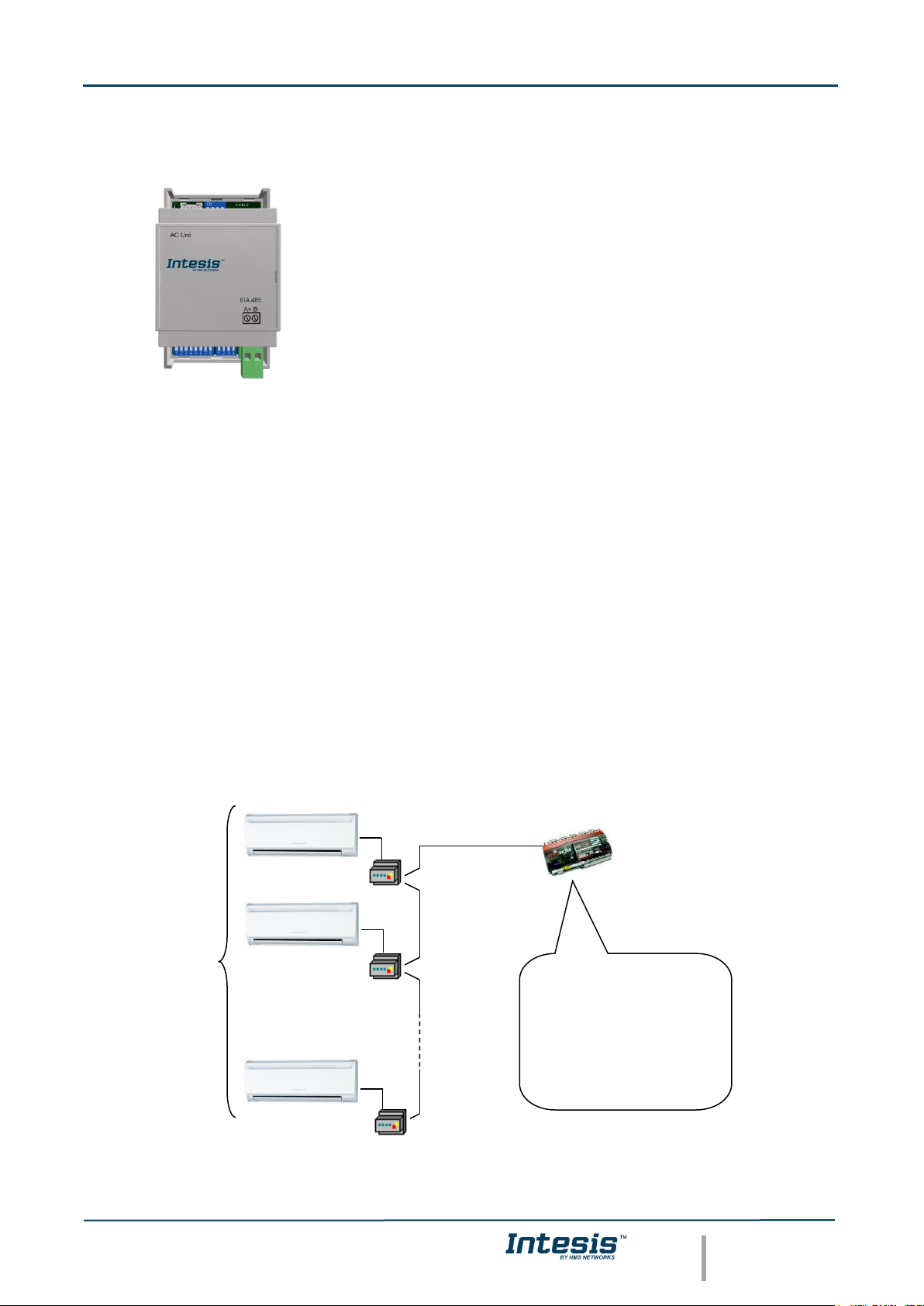
1. Presentation
The INMBSPAN001I100 interfaces allow a complete and natural
integration of Panasonic air conditioners into Modbus RTU (EIA-
485) networks.
Compatible with all models of Etherea line. Check the section 6 for
more information.
Reduced dimensions. 93 x 53 x 58 mm // 3.7” x 2.1” x 2.3”
• Quick and easy installation.
Mountable on DIN rail, wall, or even inside the indoor unit on some models of AC.
• External power not required.
• Direct connection to Modbus RTU (EIA-485) networks. Up to 63 INMBSPAN001I100 devices
can be connected on the same network.
INMBSPAN001I100 is a Modbus slave device.
• Direct connection to the AC indoor unit. Up to 1 AC indoor units can be connected to
INMBSPAN001I100. The cable for this connection is also supplied.
• Configuration from both on-board DIP-switches and Modbus RTU.
• Total Control and Supervision.
• Real states of the AC unit's internal variables.
• Allows simultaneous use of the AC’s remote controls and Modbus RTU.
* Up to 63 Intesis devices can be installed in the same Modbus RTU bus. However, depending on the configured speed, the installation
of Modbus Repeaters may be required
• SCADA
• PLC
• DDC
• BMS
• HMI
• Controller
• etc
Up to 63
AC indoor
units*
Modbus RTU
EIA-485 network
Modbus RTU
Master
device
INMBSPAN001I100
INMBSPAN001I100
INMBSPAN001I100
Page 6
IntesisTM INMBSPAN001I100
User’s Manual r1.2 EN
© HMS Industrial Networks S.L.U - All rights reserved
This information is subject to change without notice
URL https://www.intesis.com
6 / 22
2. Connection
The interface comes with a specific cable and connectors to establish direct connection with the
AC indoor unit. It comes as well with a plug-in terminal block of 2 poles to establish direct
connection with the Modbus RTU EIA-485 network.
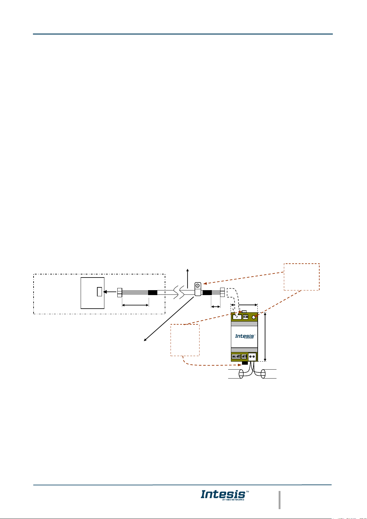
2.1 Connect to the AC indoor unit
To connect the INMBSPAN001I100 interface with the AC indoor unit you must follow these
steps:
Disconnect Mains Power from the AC unit. Open the front cover of the indoor unit to have
access to the electronic circuit. Once you arrive at the electronic circuit, locate the socket
connector marked as CN-CNT.
Take the cable that comes with the interface, insert one of its connectors (the one installed in
the shortest uncovered part) into the socket of the INMBSPAN001I100, and the other connector
(the one installed in the largest uncovered part) to the socket CN-CNT of the AC unit's
electronic circuit. You can place the INMBSPAN001I100 inside or outside the AC indoor unit
depending on your needs. Remember that the INMBSPAN001I100 must also be connected to
the Modbus RTU EIA-485 network. Close the AC indoor unit's front cover again to finish the
connection.
Do not modify the length of the cable supplied with the interface, it may affect the correct
interface´s operation.
2.2 Connection to the EIA-485 bus
Connect the EIA-485 bus wires to the plug-in terminal block (the one of two poles) of
INMBSPAN001I100 and keep the polarity on this connection (A+ and B-). Make sure that the
maximum distance to the bus is 1,200 meters (3,937 ft). Loop or star typologies are not allowed
in the case of the EIA-485 bus. A terminator resistor of 120Ω must be present at each end of
the bus to avoid signal reflections. The bus needs a fail-safe biasing mechanism (see section 4.6
for more details).
CN-CNT
AC indoor unit
Electronic control board
200 mm / 7.9”
40 mm / 1.6”
Connection cable
provided with the
interface
90 mm / 3.5”
Modbus RTU
EIA-485
Bus
EIA485
A B
AC Unit
53 mm / 2.1”
Use this hole to
attach the cable
using the staple
and the screw
provided with the
interface
For wall
mounting,
extract the
upper and
lower staples
until you listen
the "click".
Fixing screw
Page 7

IntesisTM INMBSPAN001I100
User’s Manual r1.2 EN
© HMS Industrial Networks S.L.U - All rights reserved
This information is subject to change without notice
URL https://www.intesis.com
7 / 22
3. Quick Start Guide
1. Disconnect the air conditioning from the Mains Power.
2. Attach the interface next to the AC indoor unit (wall mounting) following the instructions
of the diagram below or install it inside the AC indoor unit (respect the safety
instructions given).
3. Connect the connection cable included with the interface between the interface and the
AC indoor unit following the instructions of the diagram.
4. Connect the EIA-485 bus to the connector EIA485 of the interface.
5. Close the AC indoor unit.
6. Check the DIP-Switch configuration of the Intesis interface and make sure it matches the
current installation’s parameters (see section 4.3).
By default, the interface is set to:
▪ Modbus Slave Address ➔ 1
▪ Modbus baud rate ➔ 9600 bps
These parameters can be modified from SW4 and SW3 DIP-Switches.
All other switch positions are set at low level (Off position ) by default.
NOTE: All changes on the DIP-Switch configuration require a system power cycle to be
applied.
7. Connect the AC system to Mains Power.
IMPORTANT: The Intesis interface requires to be connected to the AC unit (powered) to
start communicating.
ON
ON
SW3
SW4
Page 8

IntesisTM INMBSPAN001I100
User’s Manual r1.2 EN
© HMS Industrial Networks S.L.U - All rights reserved
This information is subject to change without notice
URL https://www.intesis.com
8 / 22
4. Modbus Interface Specification
4.1 Modbus physical layer
INMBSPAN001I100 implements a Modbus RTU (Slave) interface, to be connected to an EIA-485
line. It performs 8N2 communication (8 data bits, no parity and 2 stop bit) with several
available baud rates (2400 bps, 4800 bps, 9600 bps, 19200 bps, 38400 bps, 57600 bps, 76800
bps and 115200 bps). It also supports 8N1 communication (8 data bits, no parity and 1 stop
bit).
4.2 Modbus Registers
All registers are type “16-bit unsigned Holding Register” and they use the standard Modbus big
endian notation.
4.2.1 Control and status registers
Register Address
(protocol address)
Register Address
(PLC address)
R/W
Description
0
1
R/W
AC unit On/Off
▪ 0: Off
▪ 1: On
1
2
R/W
AC unit Mode 1
▪ 0: Auto
▪ 1: Heat
▪ 2: Dry
▪ 3: Fan
▪ 4: Cool
2
3
R/W
AC unit Fan Speed 1
▪ 0: Auto
▪ 1: Low
▪ 2: Mid-1
▪ 3: Mid-2
▪ 4: Mid-3
▪ 5: High
3
4
R/W
AC unit Vertical Vane Position 1
▪ 0: Auto
▪ 1: Horizontal
▪ 2: Position-2
▪ 3: Position-3
▪ 4: Position-4
▪ 5: Vertical
▪ 6: Swing
4
5
R/W
AC unit Temperature setpoint
1,2,3
▪ -32768 (Initialization value)
▪ 16..30ºC (ºC/x10ºC)
▪ 61..88ºF
1
Available values will depend on the AC unit mode. Check the AC unit model functions in its user manual to know the possible values for
this register.
2
Magnitude for this register can be adjusted to Celsius x 1ºC, Celsius x 10ºC (default) or Fahrenheit. See section 4.2.3 for more
information.
3
It is not possible turn to x10 the value shown in Fahrenheit.
Page 9

IntesisTM INMBSPAN001I100
User’s Manual r1.2 EN
© HMS Industrial Networks S.L.U - All rights reserved
This information is subject to change without notice
URL https://www.intesis.com
9 / 22
Register Address
(protocol address)
Register Address
(PLC address)
R/W
Description
5
6
R
AC unit Temperature reference
1,2,3,4
▪ -32768 (Initialization value)
▪ 10..42ºC (ºC/x10ºC)
▪ 50..108ºF
6
7
R/W
Window Contact
▪ 0: Closed (Default value)
▪ 1: Open
7
8
R/W
INMBSPAN001I100 Disablement 5
▪ 0: INMBSPAN001I100 enabled (Default)
▪ 1: INMBSPAN001I100 disabled
8
9
R/W
AC Remote Control Disablement 5
▪ 0: Remote control enabled (Default)
▪ 1: Remote control disabled
9
10
R/W
AC unit Operation Time 5
▪ 0..65535 (hours). Counts the time the AC
unit is in “On” state.
10
11
R
AC unit Alarm Status
▪ 0: No alarm condition
▪ 1: Alarm condition
11
12
R
Error Code 6
▪ 0: No error present
▪ 65535 (-1 if read as a signed value): Error in
the communication of INMBSPAN001I100
with the AC unit.
▪ Any other error present, see the table at the
end of this document.
22
23
R/W
Indoor unit´s ambient temperature from
external sensor (at Modbus side)
1,2,3,7
▪ -32768: (Initialization value). No
temperature is being provided from an
external sensor.
▪ Any other: (ºC/x10ºC/ºF)
23
24
R
AC Real temperature setpoint
1,2,3,7
▪ When no external temperature is provided,
this read-only register will have the same
value as register 5 (PLC addressing). In all
cases, it will show the current setpoint in the
indoor unit.
▪ 16..31ºC (ºC/x10ºC)
▪ 60..92ºF
24
25
R
Current AC max. setpoint
1,2,3
▪ -32768 (Initialization value)
▪ 30ºC (ºC/x10ºC)
▪ 86ºF
25
26
R
Current AC min. setpoint
1,2,3
▪ -32768 (Initialization value)
▪ 16ºC (ºC/x10ºC)
▪ 61ºF
4
Feature only available on 2013 models (PKE series) and onwards.
5
This value is stored in non-volatile memory
6
See section 7 for possible error codes and their explanation
7
See section 4.2.3 for more information
Page 10

IntesisTM INMBSPAN001I100
User’s Manual r1.2 EN
© HMS Industrial Networks S.L.U - All rights reserved
This information is subject to change without notice
URL https://www.intesis.com
10 / 22
Register Address
(protocol address)
Register Address
(PLC address)
R/W
Description
26
27
R/W
AC unit Horizontal Vane Position 1
▪ 0: Auto
▪ 1: Horizontal
▪ 2: Position-2
▪ 3: Position-3
▪ 4: Position-4
▪ 5: Vertical
37
38
R
Auto mode
▪ 0: Auto (Default value)
▪ 1: Heat
▪ 2: Dry
▪ 3: Fan
▪ 4: Cool
38
39
R/W
Powerful
▪ 0: Off (Default value)
▪ 1: On
39
40
R/W
Quiet
▪ 0: Off (Default value)
▪ 1: On
53
54
R
Compressor Status
▪ 0: Off (Default value)
▪ 1: To off
▪ 2: To on
▪ 3: On
54
55
R/W
Compressor On Time 5
▪ 0..65535 (hours)
55
56
R/W
Under voltage Count
▪ 0..300
56
57
R/W
Heat 8/10 ºC Mode
1,8
▪ 0: Off (Default value)
▪ 1: On
57
58
R/W
ECO Mode 4
▪ 0: Off (Default value)
▪ 1: ECONAVI
▪ Auto Comfort
58
59
R
Demand Response (DRM level) 4
▪ 0: Normal (Default value)
▪ 1: Comp OFF (DRM1)
▪ 2: 50% (DRM2)
▪ 3: 75% (DRM3)
59
60
R
Human Activity
4
▪ 0: Exist (Default value)
▪ 1: Not Exist
60
61
R
Outdoor intake temperature
1,2,3,4
▪ -32768: (initialization value) No
temperature’s value is being provided from
an external sensor.
▪ Any other: (ºC/x10ºC/ºF)
61
62
R
Power Consumption
4,9
▪ Value expressed in W
62
63
R
Operation Current
4,9
▪ Value expressed in mA
8
When the value is 1 means that the value goes between 5ºC and 8ºC.
9
The reading of this register equals to the consumption of the full AC system, not the consumption from one single unit.
Page 11

IntesisTM INMBSPAN001I100
User’s Manual r1.2 EN
© HMS Industrial Networks S.L.U - All rights reserved
This information is subject to change without notice
URL https://www.intesis.com
11 / 22
Register Address
(protocol address)
Register Address
(PLC address)
R/W
Description
63
64
R
Power Consumption (Slow)
4,9
▪ Value expressed in W. The frequency of the
updates is lower than the one of register 61
(62 PLC)
65
66
R
Input reference temperature 4
▪ -32768: (initialization value) No
temperature’s value is being provided from
an external sensor.
▪ Any other: (ºC/x10ºC/ºF)
66
67
R
Return path temperature
1,2,3
▪ Temperature on the air return of the AC unit
(ºC/x10ºC/ºF).
72
73
R
Today Energy – MSW
4,10
▪ 0..65535 (hours). Value expressed in Watt-
hour (Energy consumption throughout the
day).
73
74
R
Today Energy – lsw
4,10
▪ 0..65535 (hours). Value expressed in Watt-
hour (Energy consumption throughout the
day).
74
75
R
Yesterday Energy – MSW
4,10
▪ 0..65535 (hours). Value expressed in Watt-
hour (Energy consumption throughout the
previous day).
75
76
R
Yesterday Energy – lsw
4,10
▪ 0..65535 (hours). Value expressed in Watt-
hour (Energy consumption throughout the
previous day).
76
77
R/W
Total Energy – MSW
4,10
▪ 0..65535 (hours). Value expressed in Watt-
hour
77
78
R/W
Total Energy – lsw
4,10
▪ 0..65535 (hours). Value expressed in Watt-
hour
97
98
R/W
Block Periodic Sendings
11,12
▪ 0: Non-blocked (Default value)
▪ 1: Blocked
10
MSW is related to the concept Most Significant word and lsw is related to the concept Least Significant word.
11
If the register is configured as “0:Non-blocked”, all commands received from Modbus will be sent to the AC system. If “1: Blocked”, all
commands received from Modbus will be sent to the AC system if they differ from the previous value.
12
This register applies to firmware version 2.3 onwards
Page 12

IntesisTM INMBSPAN001I100
User’s Manual r1.2 EN
© HMS Industrial Networks S.L.U - All rights reserved
This information is subject to change without notice
URL https://www.intesis.com
12 / 22
4.2.2 Configuration Registers
Register Address
(protocol address)
Register Address
(PLC address)
R/W
Description
13
14
R/W
“Open Window” switch-off timeout 13
▪ 0..30 (minutes)
▪ Factory setting: 30 (minutes)
14
15
R
Modbus RTU baud-rate
▪ 2400bps
▪ 4800bps
▪ 9600bps (Default)
▪ 19200bps
▪ 38400bps
▪ 57600bps
▪ 76800bps
▪ 115200bps
15
16
R
Device's Modbus Slave address
▪ 1..63
21
22
R
Max. number of fan speeds
49
50
R
Device ID: 0x0C00
50
51
R
Software version
78
79
R/W
Today: Year 4
▪ 2000: Default value
▪ Value expressed without units (It shows the
year configured).
79
80
R/W
Today: Month 4
▪ 1: Default value
▪ Value expressed without units (It shows the
month configured).
80
81
R/W
Today: Day 4
▪ 0: Default value
▪ Value expressed without units (It shows the
day configured).
4.2.3 Considerations on Temperature Registers
• AC unit temperature setpoint (R/W)
(register 4 – in Protocol address / register 5 – in PLC address):
This is the adjustable temperature setpoint value that must be required by the user. This
register can be read (Modbus function 3 or 4) or written (Modbus functions 6 or 16). A
remote controller connected to the Panasonic indoor unit will report the same
temperature setpoint value as this register, but only will happen when no AC unit´s
external reference is provided from INMBSPAN001I100 (see detail for register 22/23
below).
• AC unit temperature reference (R)
(register 5 – in Protocol address / register 6 – in PLC address):
This register reports the temperature that is currently used by the Panasonic indoor unit
as the reference of its own control loop. Depending on the configuration of the indoor
unit, this value can be the temperature reported by the sensor on the return path of the
Panasonic indoor unit or the sensor of its remote controller. It is a read-only register
(Modbus functions 3 or 4).
13
Once window contact is open, a count-down to switch off the AC Unit will start from this configured value.
Page 13

IntesisTM INMBSPAN001I100
User’s Manual r1.2 EN
© HMS Industrial Networks S.L.U - All rights reserved
This information is subject to change without notice
URL https://www.intesis.com
13 / 22
• AC unit external temperature reference (Modbus) (R/W)
(register 22 – in Protocol address / register 23 – in PLC address):
This register allows us to provide an external temperature reference from the Modbus
side. Panasonic indoor unit does not allow on devices like INMBSPAN001I100 to provide
directly temperature to be used as a reference of the control loop of the AC indoor unit.
In order to overcome this limitation and enable the usage of an external temperature
sensor (i.e. in Modbus side), INMBSPAN001I100 applies the following mechanism (only if
“external temperature’s reference” is being used):
o After a couple of values have been entered in the “AC unit external temperature’s
reference” (register 22/23) and “AC unit temperature set point” (register 4/5),
INMBSPAN001I100 is going to estimate the temperature chosen implied (e.g. if a
“temperature setpoint (register 4/5)” of 22ºC, and an “external temperature
reference (register 22/23)” of 20ºC are entered, INMBSPAN001I100 will assume
that the user is demanding a +2ºC increase in temperature).
o By knowing at any time the ambient temperature currently used by the indoor
unit to control its own operation (register 5/6), INMBSPAN001I100 can calculate
the required temperature setpoint needed to apply the decrease/increase on the
real temperature and reach the temperature chosen by the user (following the
example above, if INMBSPAN001I100 reads an “ambient temperature” (register
5/6) of 24ºC in the indoor unit, it will apply a final setpoint of 24ºC + 2ºC =
26ºC).
o At this moment, each time that INMBSPAN001I100 detects a change on the
ambient temperature reported by the indoor unit (register 5/6), it will also change
the required setpoint, in order to keep the temperature required by the user at
any time. If we follow the last example, if INMBSPAN001I100 receives a new
temperature´s value coming from the indoor unit of 25ºC, INMBSPAN001I100 will
automatically adjust the temperature setpoint required of the AC indoor unit to
25ºC + 2ºC = 27ºC).
o In general, INMBSPAN001I100 is constantly applying the “Virtual Temperature”
formula:
SAC = Su – ( Tu – T
AC
)
Where:
SAC - setpoint value currently applied to the indoor unit
Su - setpoint value written at Modbus side (register 4/5)
Tu - external temperature reference written at Modbus side (register 22/23)
TAC - ambient temperature that the indoor unit is using as the reference of its
own control loop (register 5/6)
When INMBSPAN001I100 detects a change in any of the values of
{ Su , Tu , TAC }, it will send the new setpoint (SAC) to the indoor unit.
o After the startup, the value for “external temperature’s reference” (register
22/23) has a value -32768 (0x8000). This value means that no external
temperature reference is being provided through INMBSPAN001I100. In this
scenario, the setpoint value shown in register 4/5 will always be the same as the
current setpoint value of the indoor unit.
o Notice that, the use of the “external temperature reference” (register 22/23)
(e.g., writing a value different from -32768 / 0x8000 in it) has the following
relevant consequences:
Page 14

IntesisTM INMBSPAN001I100
User’s Manual r1.2 EN
© HMS Industrial Networks S.L.U - All rights reserved
This information is subject to change without notice
URL https://www.intesis.com
14 / 22
▪ The mechanism of “Virtual Temperature” is applied. The temperature
setpoint’s value shown by the Remote Controller or other Control System
from Panasonic connected to the indoor unit may show a different value
from the value shown in register 4/5.
▪ The User is not be able to change the setpoint using any Remote Controller
from Panasonic, as setpoint of the indoor unit becomes exclusively
controlled by the “Virtual Temperature” mechanism.
• AC Real temperature setpoint (R)
(register 23 – In Protocol address / register 24 – in PLC address):
As it has been detailed on the previous point, the real temperature setpoint in the indoor
unit and the temperature setpoint requested from INMBSPAN001I100 might differ (when
a value in register 22/23 – “external temperature reference” is entered). This register
always informs about the current temperature setpoint which is being used by the indoor
unit – it is also includes the temperature setpoint that will be shown by an additional
remote controller from Panasonic connected to the indoor unit, if it is present on the
system.
Moreover, notice that temperature’s values of all these four registers are expressed according to
the temperature´s format configured through its onboard DIP-Switches (See “4.3 - DIP-switch
Configuration Interface”). These following formats are possible:
• Celsius value: Value in Modbus register is the temperature value in Celsius (i.e. a
value “22” in the Modbus register must be interpreted as 22ºC).
• Decicelsius value: Value in Modbus register is the temperature value in
decicelsius (i.e. a value “220” in the Modbus register must be interpreted as
22.0ºC).
• Fahrenheit value: Value in Modbus register is the temperature value in
Fahrenheit (i.e. a value “72” in the Modbus register must be interpreted as 72ºF
(~22ºC).
Page 15

IntesisTM INMBSPAN001I100
User’s Manual r1.2 EN
© HMS Industrial Networks S.L.U - All rights reserved
This information is subject to change without notice
URL https://www.intesis.com
15 / 22
4.3 DIP-switch Configuration Interface
All the configuration values on INMBSPAN001I100 can be written and read from Modbus
interface. Otherwise, some of them can also be setup from its on-board DIP-switch interface.
The device has DIP-switches SW1, SW3 and SW4 on the following locations:
The following tables apply to the interface´s configuration through DIP-switches:
SW1 – AC indoor unit’s configuration
SW1-P1..4
Description
AC unit does not have FAN mode (Panasonic AC unit does not have FAN mode available).
AC unit has FAN mode (Default mode) (Panasonic AC unit has FAN mode available).
AC unit does not have horizontal vanes.
AC unit has horizontal vanes (Default value).
Keep the switch into this position (Default value).
Do not turn the switch into this position (not applicable).
Keep the switch into this position (Default value).
Do not turn the switch into this position (not applicable).
SW3
SW4
K1
FIXING
CABLE
EIA485
A B
AC Unit
SW1
SW1
SW4
ON SAB
1 2 3 4
SW3
1 2 3 4
1 2 3 4 5 6 7 8
ON SAB
ON SAB
ON SAB
ON SAB
ON SAB
ON SAB
ON SAB
ON SAB
ON SAB
ON SAB
Page 16

IntesisTM INMBSPAN001I100
User’s Manual r1.2 EN
© HMS Industrial Networks S.L.U - All rights reserved
This information is subject to change without notice
URL https://www.intesis.com
16 / 22
Table 4.1 SW1: AC indoor unit’s configuration
SW3/SW4 – Baud rate configuration
SW3-P7..8
SW4-P3
Description
2400bps
4800bps
9600bps (Default)
19200bps
38400bps
57600bps
76800bps
115200bps
Table 4.2 SW3-SW4: Modbus baud rate
SW4 – Degrees/Decidegrees (x10), temperature magnitude (ºC/ºF) and EIA-485 termination
resistor.
Table 4.3 SW4: Temperature and termination resistor configuration
SW4-P1..2-4
Description
Temperature values in Modbus register are represented in degrees (x1) (Default value)
Temperature values in Modbus register are represented in decidegrees (x10)
Temperature values in Modbus register are represented in Celsius degrees (Default value)
Temperature values in Modbus register are represented in Fahrenheit degrees
EIA-485 bus without termination resistor (Default value)
Internal termination resistor of 120Ω connected to EIA-485 bus
ON SAB
ON SAB
ON SAB
ON SAB
ON SAB
ON SAB
ON SAB
ON SAB
ON SAB
ON SAB
ON SAB
ON SAB
ON SAB
ON SAB
ON SAB
ON SAB
ON SAB
ON SAB
ON SAB
ON SAB
ON SAB
ON SAB
Page 17

IntesisTM INMBSPAN001I100
User’s Manual r1.2 EN
© HMS Industrial Networks S.L.U - All rights reserved
This information is subject to change without notice
URL https://www.intesis.com
17 / 22
SW3 – Modbus Slave address
Table 4.4 SW3: Modbus slave address
Add SW3-P1..6
Add SW3-P1..6
Add SW3-P1..6
Add
SW3-P1..6
Add
SW3-P1..6
0
13
26
39
52
1
14
27
40
53
2
15
28
41
54
3
16
29
42
55
4
17
30
43
56
5
18
31
44
57
6
19
32
45
58
7
20
33
46
59
8
21
34
47
60
9
22
35
48
61
10
23
36
49
62
11 24 37 50 63
12 25 38 51
ON SAB
ON SAB
ON SAB
ON SAB
ON SAB
ON SAB
ON SAB
ON SAB
ON SAB
ON SAB
ON SAB
ON SAB
ON SAB
ON SAB
ON SAB
ON SAB
ON SAB
ON SAB
ON SAB
ON SAB
ON SAB
ON SAB
ON SAB
ON SAB
ON SAB
ON SAB
ON SAB
ON SAB
ON SAB
ON SAB
ON SAB
ON SAB
ON SAB
ON SAB
ON SAB
ON SAB
ON SAB
ON SAB
ON SAB
ON SAB
ON SAB
ON SAB
ON SAB
ON SAB
ON SAB
ON SAB
ON SAB
ON SAB
ON SAB
ON SAB
ON SAB
ON SAB
ON SAB
ON SAB
ON SAB
ON SAB
ON SAB
ON SAB
ON SAB
ON SAB
ON SAB
ON SAB
ON SAB
ON SAB
Page 18

IntesisTM INMBSPAN001I100
User’s Manual r1.2 EN
© HMS Industrial Networks S.L.U - All rights reserved
This information is subject to change without notice
URL https://www.intesis.com
18 / 22
4.4 Implemented Functions
INMBSPAN001I100 implements the following standard Modbus functions:
▪ 3: Read Holding Registers
▪ 4: Read Input Registers
▪ 6: Write Single Register
▪ 16: Write Multiple Registers (Despite this function is allowed, the interface does not
allow to write operations on more than 1 register with the same request, this means that
length field should be always be 1 when this function is being used in case of writing)
4.5 Device LED indicator
The device includes a LED indicator to show all the possible operational states. In the following
table there are written the indicators which can be performed and its meaning.
Device status
LED indication
ON / OFF Period
Description
On power-up
LED pulse
ON for 5 seconds / OFF after
Device reset / power-up
During normal
operation
LED flashing
200ms ON / 2s OFF
Device correctly configured and
working
During normal
operation
LED OFF
OFF continuously
No Modbus Slave address configured
During normal
operation
LED blinking
200ms ON / 200ms OFF
Communication Error with the AC
unit
4.6 EIA-485 bus. Termination resistors and Fail-Safe Biasing
mechanism
EIA-485 bus requires a 120Ω terminator resistor at each end of the bus to avoid signal
reflections.
In order to prevent fail status detected by the receivers, which are “listening” the bus, when all
the transmitters’ outputs are in three-state (high impedance), it is also required a fail-safe
biasing mechanism. This mechanism provides a safe status (a correct voltage level) in the bus
when all the transmitters’ outputs are in three-state. This mechanism must be supplied by the
Modbus Master.
The INMBSPAN001I100 device includes an on-board terminator resistor of 120Ω that can be
connected to the EIA-485 bus by using DIP-switch SW4 (see below).
Some Modbus RTU EIA-485 Master devices can provide also internal 120Ω terminator resistor
and/or fail-safe biasing (check the technical documentation of the Master device connected to
the EIA-485 network in each case).
Page 19

IntesisTM INMBSPAN001I100
User’s Manual r1.2 EN
© HMS Industrial Networks S.L.U - All rights reserved
This information is subject to change without notice
URL https://www.intesis.com
19 / 22
5. Electrical and Mechanical features
Enclosure
Plastic, type PC (UL 94 V-0)
Net dimensions (dxwxh):
93 x 53 x 58 mm / 3.7” x 2.1” x 2.3”
Color: Light Grey. RAL 7035
Operation
Temperature
0ºC to +60ºC
Weight
85 g.
Stock
Temperature
-20ºC to +85ºC
Mounting
Wall
DIN rail EN60715 TH35.
Operational
Humidity
<95% RH, non-condensing
Terminal Wiring
(for low-voltage
signals)
For terminal: solid wires or stranded wires
(twisted or with ferrule)
1 core: 0.5mm2… 2.5mm2
2 cores: 0.5mm2… 1.5mm2
3 cores: not permitted
Stock Humidity
<95% RH, non-condensing
Modbus RTU
port
1 x Serial EIA485 Plug-in screw terminal
block (2 poles)
A, B
Compatible with Modbus RTU EIA-485
networks
Isolation voltage
1500 VDC
AC unit port
1 x Specific connector
Specific cable included
Isolation
resistance
1000 MΩ
Switch 1
(SW1)
1 x DIP-Switch for AC features
Protection
IP20 (IEC60529)
Switch 3
(SW3)
1 x DIP-Switch for Modbus RTU settings
LED indicators
1 x Onboard LED - Operational
status
Switch 4
(SW4)
1 x DIP-Switch for extra functions
EIA-485 Port
AC Unit
connection
DIP
Switch SW3
DIP
Switch SW1
LED
Indicator
DIP
Switch SW4
Page 20

IntesisTM INMBSPAN001I100
User’s Manual r1.2 EN
© HMS Industrial Networks S.L.U - All rights reserved
This information is subject to change without notice
URL https://www.intesis.com
20 / 22
6. List of supported AC Unit Types.
A list of Panasonic indoor unit model’s references compatible with INMBSPAN001I100 and its
available features can be found on this link:
http://www.intesis.com/docs/compatibilities/inxxxpan001ix00_compatibility
Page 21

IntesisTM INMBSPAN001I100
User’s Manual r1.2 EN
© HMS Industrial Networks S.L.U - All rights reserved
This information is subject to change without notice
URL https://www.intesis.com
21 / 22
7. Error Codes
Error
Code
Modbus
Error
in RC
Abnormality /
Protection control
Abnormality
Judgment
Problem
Check Location
0
N/A
— —
No error active —
65535
(-1)
N/A
— —
Error in the communication
of INMBSPAN001I100 with
the AC unit
• Indoor/gateway connection wire
8209
H11
Indoor/outdoor
abnormal
communication
After operation for
1 minute
Indoor/outdoor
communication not
establish
• Indoor/outdoor wire terminal
• Indoor/outdoor PCB
• Indoor/outdoor connection wire
8210
H12
Indoor unit capacity
unmatched
90s after power
supply
Total indoor capability more
than maximum limit or less
than minimum limit, or
number of indoor unit less
than two.
• Indoor/outdoor connection wire
• Indoor/outdoor PCB
• Specification and combination
table in catalogue
8212
H14
Indoor intake air
temperature sensor
abnormality
Continuous for 5s
Indoor intake air
temperature sensor open
or short circuit
• Indoor intake air temperature
sensor lead wire and connector
8213
H15
Compressor temperature
sensor abnormality
Continuous for 5s
Compressor temperature
sensor open or short circuit
• Compressor temperature sensor
lead wire and connector
8214
H16
Outdoor current
transformer (CT)
abnormality
—
Current transformer faulty
or compressor faulty
• Outdoor PCB faulty or
compressor faulty
8217
H19
Indoor fan motor
mechanism lock
Continuous
happen for 7 times
Indoor fan motor lock or
feedback abnormal
• Fan motor lead wire and
connector
• Fan motor lock or block
8227
H23
Indoor heat exchanger
temperature sensor
abnormality
Continuous for 5s
Indoor heat exchanger
temperature sensor open
or short circuit
• Indoor heat exchanger temperature
sensor lead wire and connector
8229
H25
Indoor E-Ion abnormality
Port is ON for 10s
during E-Ion off
—
• E-Ion PCB
8231
H27
Outdoor air temperature
sensor abnormality
Continuous for 5s
Outdoor air temperature
sensor open or short circuit
• Outdoor air temperature sensor
lead wire and connector
8232
H28
Outdoor heat
exchanger
temperature sensor 1
abnormality
Continuous for 5s
Outdoor heat exchanger
temperature sensor 1 open
or short circuit
• Outdoor heat exchanger
temperature sensor 1 lead wire
and connector
8240
H30
Outdoor discharge pipe
temperature sensor
abnormality
Continuous for 5s
Outdoor discharge pipe
temperature sensor open
or short circuit
• Outdoor discharge pipe
temperature sensor lead wire and
connector
8242
H32
Outdoor heat
exchanger
temperature sensor 2
abnormality
Continuous for 5s
Outdoor heat exchanger
temperature sensor 2 open
or short circuit
• Outdoor heat exchanger
temperature sensor 2 lead wire
and connector
8243
H33
Indoor / outdoor
misconnection
abnormality
—
Indoor and outdoor rated
voltage different
• Indoor and outdoor units check
8244
H34
Outdoor heat sink
temperature sensor
abnormality
Continuous for 2s
Outdoor heat sink
temperature sensor open
or short circuit
• Outdoor heat sink sensor
8246
H36
Outdoor gas pipe
temperature sensor
abnormality
Continuous for 5s
Outdoor gas pipe
temperature sensor open
or short circuit
• Outdoor gas pipe temperature
sensor lead wire and connector
8247
H37
Outdoor liquid pipe
temperature sensor
abnormality
Continuous for 5s
Outdoor liquid pipe
temperature sensor open
or short circuit
• Outdoor liquid pipe temperature
sensor lead wire and connector
8248
H38
Indoor/Outdoor
mismatch (brand code)
—
Brand code not match
• Check indoor unit and outdoor
unit.
Page 22

IntesisTM INMBSPAN001I100
User’s Manual r1.2 EN
© HMS Industrial Networks S.L.U - All rights reserved
This information is subject to change without notice
URL https://www.intesis.com
22 / 22
8249
H39
Abnormal indoor
operating unit or standby
units
3 times happen
within 40 minutes
Wrong wiring and
connecting pipe, expansion
valve abnormality, indoor
heat exchanger sensor
open circuit
• Check indoor/outdoor connection
wire and connection pipe
• Indoor heat exchanger sensor
lead wire and connector
• Expansion valve and lead wire
and connector
8257
H41
Abnormal wiring or piping
connection
—
Wrong wiring and
connecting pipe, expansion
valve abnormality
• Check indoor/outdoor connection
wire and connection pipe
• Expansion valve and lead wire
and connector.
8280
H58
Indoor gas sensor
abnormality
Continuous for 6
hours
Indoor gas sensor open or
short circuit
• Indoor gas sensor
• Indoor PCB
8281
H59
ECO patrol sensor
abnormality
Continuous for
70s
ECO patrol sensor open or
short circuit
• ECO patrol sensor
• ECO patrol and Indoor PCB
8292
H64
Outdoor high pressure
sensor abnormality
Continuous for 1
minutes
High pressure sensor open
circuit during compressor
stop
• High pressure sensor
• Lead wire and connector
8343
H97
Outdoor fan motor
mechanism lock
2 times happen
within 30 minutes
Outdoor fan motor lock or
feedback abnormal
• Outdoor fan motor lead wire and
connector
• Fan motor lock or block
8344
H98
Indoor high pressure
protection
—
Indoor high pressure
protection (Heating)
• Check indoor heat exchanger
• Air filter dirty
• Air circulation short circuit
8345
H99
Indoor operating unit
freeze protection
—
Indoor freeze protection
(Cooling)
• Check indoor heat exchanger
• Air filter dirty
• Air circulation short circuit
12305
F11
4-way valve switching
abnormality
4 times happen
within 30 minutes
4-way valve switching
abnormal
• 4-way valve
• Lead wire and connector.
12311
F17
Indoor standby units
freezing abnormality
3 times happen
within 40 minutes
Wrong wiring and
connecting pipe, expansion
valve leakage, indoor heat
exchanger sensor open
circuit
• Check indoor/outdoor connection
wire and pipe
• Indoor heat exchanger sensor
lead wire and connector
• Expansion valve lead wire and
connector.
12432
F90
Power factor correction
(PFC) circuit protection
4 times happen
within 10 minutes
Power factor correction
circuit abnormal
• Outdoor PCB faulty
12433
F91
Refrigeration cycle
abnormality
2 times happen
within 20 minutes
Refrigeration cycle
abnormal
• Insufficient refrigerant or valve
close
12435
F93
Compressor abnormal
revolution
4 times happen
within 20 minutes
Compressor abnormal
revolution
• Power transistor module faulty or
compressor lock
12436
F94
Compressor discharge
pressure overshoot
protection
4 times happen
within 30 minutes
Compressor discharge
pressure overshoot
• Check refrigeration system
12437
F95
Outdoor cooling high
pressure protection
4 times happen
within 20 minutes
Cooling high pressure
protection
• Check refrigeration system
• Outdoor air circuit
12438
F96
Power transistor
module
overheating protection
4 times happen
within 30 minutes
Power transistor module
overheat
• PCB faulty
• Outdoor air circuit (fan motor)
12439
F97
Compressor overheating
protection
3 times happen
within 30 minutes
Compressor overheat
• Insufficient refrigerant
12440
F98
Total running current
protection
3 times happen
within 20 minutes
Total current protection
• Check refrigeration system
• Power source or compressor lock
12441
F99
Outdoor direct current
(DC) peak detection
Continuous
happen for 7 times
Power transistor module
current protection
• Power transistor module faulty or
compressor lock
In case to detect an error code not listed, contact your closest Panasonic technical support
service.
 Loading...