

Page 1
M-Bus
USER MANUAL
Issue date: 08/2019 r1.4 ENGLISH
Page 2

IntesisTM Modbus Server – M-Bus User Manual r1.4 EN
© HMS Industrial Networks S.L.U - All rights reserved
This information is subject to change without notice
URL https://www.intesis.com
2 / 20
Important User Information
Disclaimer
The information in this document is for informational purposes only. Please inform HMS Industrial Networks of any
inaccuracies or omissions found in this document. HMS Industrial Networks disclaims any responsibility or liability for
any errors that may appear in this document.
HMS Industrial Networks reserves the right to modify its products in line with its policy of continuous product
development. The information in this document shall therefore not be construed as a commitment on the part of
HMS Industrial Networks and is subject to change without notice. HMS Industrial Networks makes no commitment
to update or keep current the information in this document.
The data, examples and illustrations found in this document are included for illustrative purposes and are only
intended to help improve understanding of the functionality and handling of the product. In view of the wide range
of possible applications of the product, and because of the many variables and requirements associated with any
particular implementation, HMS Industrial Networks cannot assume responsibility or liability for actual use based on
the data, examples or illustrations included in this document nor for any damages incurred during installation of the
product. Those responsible for the use of the product must acquire sufficient knowledge in order to ensure that the
product is used correctly in their specific application and that the application meets all performance and safety
requirements including any applicable laws, regulations, codes and standards. Further, HMS Industrial Networks will
under no circumstances assume liability or responsibility for any problems that may arise as a result from the use of
undocumented features or functional side effects found outside the documented scope of the product. The effects
caused by any direct or indirect use of such aspects of the product are undefined and may include e.g. compatibility
issues and stability issues.
Page 3

IntesisTM Modbus Server – M-Bus User Manual r1.4 EN
© HMS Industrial Networks S.L.U - All rights reserved
This information is subject to change without notice
URL https://www.intesis.com
3 / 20
Gateway for the integration of M-Bus meters into Modbus RTU
and/or Modbus TCP monitoring and control systems.
ORDER CODE
LEGACY ORDER CODE
INMBSMEB0100000
IBMBSMEB0100000
INMBSMEB0200000
IBMBSMEB0200000
INMBSMEB0600000
IBMBSMEB0600000
INMBSMEB1200000
IBMBSMEB1200000
Page 4

IntesisTM Modbus Server – M-Bus User Manual r1.4 EN
© HMS Industrial Networks S.L.U - All rights reserved
This information is subject to change without notice
URL https://www.intesis.com
4 / 20
INDEX
1 Description ............................................................................................................................................... 5
Introduction ....................................................................................................................................... 5
Functionality ..................................................................................................................................... 6
Gateway’s capacity .......................................................................................................................... 7
2 M-Bus System .......................................................................................................................................... 8
Description ........................................................................................................................................ 8
M-Bus interface ................................................................................................................................ 8
M-Bus signals ................................................................................................................................... 8
3 Modbus interface of Intesis .................................................................................................................... 10
Description ...................................................................................................................................... 10
Functions supported ....................................................................................................................... 10
Modbus RTU .................................................................................................................................. 10
Modbus TCP ................................................................................................................................... 10
Address Map .................................................................................................................................. 10
Points definition .............................................................................................................................. 11
4 Connections ........................................................................................................................................... 12
Powering the device ....................................................................................................................... 13
Connection to M-Bus ...................................................................................................................... 13
Connection to Modbus ................................................................................................................... 13
4.3.1 Modbus TCP ........................................................................................................................... 13
4.3.2 Modbus RTU ........................................................................................................................... 13
Connection to the configuration tool ............................................................................................... 13
5 Set-up process and troubleshooting ...................................................................................................... 14
Pre-requisites ................................................................................................................................. 14
Intesis MAPS. Configuration & monitoring tool for Intesis Modbus series ..................................... 14
5.2.1 Introduction ............................................................................................................................. 14
5.2.2 Connection .............................................................................................................................. 14
5.2.3 Configuration tab .................................................................................................................... 15
5.2.4 Signals .................................................................................................................................... 15
5.2.5 Sending the configuration to Intesis ....................................................................................... 16
5.2.6 Diagnostic ............................................................................................................................... 16
Set-up procedure ............................................................................................................................ 18
6 Electrical & Mechanical Features ........................................................................................................... 19
7 Dimensions ............................................................................................................................................ 20
Page 5
IntesisTM Modbus Server – M-Bus User Manual r1.4 EN
© HMS Industrial Networks S.L.U - All rights reserved
This information is subject to change without notice
URL https://www.intesis.com
5 / 20
1 Description
Introduction
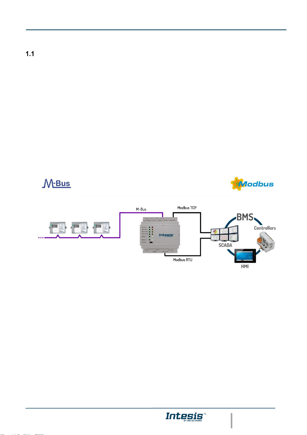
This document describes the integration of M-Bus devices into Modbus RTU and Modbus TCP systems using the
Intesis Modbus Slave – M-Bus gateway.
The aim of this integration is to make accessible M-Bus devices from a Modbus control system or device, as if it was
part of the own Modbus installation.
For this, Intesis acts as a Modbus TCP server or Modbus RTU slave device in its Modbus interface, allowing
read/write points from the Modbus client device(s). From the M-Bus point of view, Intesis acts as a M-Bus level
converter and master device (EN-1434-3). The readings of the M-Bus slave device(s) are performed by Intesis by
automatic continuous polling or underdemand (to avoid batteries on meters run out).
Configuration is carried out using the configuration software IntesisTM MAPS.
This document assumes that the user is familiar with M-Bus and Modbus technologies and their technical terms.
Integration of M-Bus devices into Modbus TCP
or Modbus RTU control and monitoring systems
Page 6

IntesisTM Modbus Server – M-Bus User Manual r1.4 EN
© HMS Industrial Networks S.L.U - All rights reserved
This information is subject to change without notice
URL https://www.intesis.com
6 / 20
Functionality
Intesis polls, either continuously or only when ordered from the Modbus side, the M-Bus devices to obtain updated
readings for the points configured in it (the points corresponding to measures and states of the meters in the
integration points list explained later in this document). With every read, the new values received are updated in the
Intesis's memory and become available in the Modbus side. When a change in any point configured as output in
Intesis is detected (this is written from the Modbus side), the corresponding action in the M-Bus device will be
performed. These actions can be: force a polling of a specific M-Bus device or force a polling of all M-Bus devices.
The polling of a specific M-Bus device, or of all M-Bus devices, can be forced in any moment from the Mobus side
by writing a 1 in the corresponding binary point specially enabled for this purpose in the Intesis.
The automatic continuous polling of all M-Bus devices can be activated/deactivated writing from Modbus in a specific
binary point specially enabled for this purpose in the Intesis.
Other M-Bus information accessible from Modbus, using specific points of the Intesis, is:
• Bus activity (indicates if meters are currently being polled or if polling is in stand-by).
• M-Bus status of every meter (this M-Bus status is sent by the own meter with every poll and indicates the
internal status, manufacturer specific in every case).
These are the main features of the M-Bus interface of Intesis:
• Embedded level converter. Direct connection to M-Bus devices with no extra hardware required.
• Scan option to automatically detect M-Bus devices and its available registers.
• Import/Export of M-Bus device templates.
• EIA485 two wires (plug-in terminal bloc with screws) connection.
• Baud rate configurable from 300 to 9600 bps (allowed baud rates in M-Bus. The devices are normally
configured at 2400 bps at the factory).
• Primary or secondary addressing allowed.
• Useful timeouts and specific parameters to make the interface widely compatible with many meter's
peculiarities found usually between different manufacturers.
• Polling of the meters can be continuously, either configured in the own Intesis or you can activate/deactivate
continuous polling of the meters from Modbus side using a special datapoint.
• You can force a polling of the meters (refresh of readings) in any moment from Modbus side using special
datapoints: one datapoint to force a polling of all the meters, and one specific datapoint per meter to force
the polling of the individual meter.
• Intesis can also be configured to make a single polling of the meters (refresh of readings) at the start up.
• For each meter, a datapoint is available in Modbus indicating communication error with the meter, also a
general communication error datapoint is available (that will be active whenever the communication with
one or more meters has failed).
• Fully flexible configuration of the registers to poll in the meter, to adapt to any meter.
Every meter, depending on manufacturer and model, offers different type of signals from the mentioned before. To
know what signals offers the meter and of what type, to be able to integrate those wanted, refer to the device technical
documentation. Anyway, and to ease and speed up the identification of the signals offered by any device (and of
what type), the scan option is highly recommended or the import of templates too.
Page 7

IntesisTM Modbus Server – M-Bus User Manual r1.4 EN
© HMS Industrial Networks S.L.U - All rights reserved
This information is subject to change without notice
URL https://www.intesis.com
7 / 20
Gateway’s capacity
Intesis capacity is listed below:
Element
10
version
20
version
60
version
120
version
Notes
Type of Modbus
Master devices
Modbus RTU (EIA485 or EIA232)
Modbus TCP
Those supporting Modbus protocol.
Communication over TCP/IP and RTU.
Number of Modbus
Master devices
1 Master device per RTU Node
Up to 6 TCP connections
Number of Modbus Master devices
supported by the device.
Number of Modbus
registers
250
500
1500
3000
Maximum number of points that can be
defined in the virtual Modbus Slave/Server
device inside the gateway.
Type of M-Bus
devices
M-Bus EIA485 Slave devices
Those supporting M-Bus EN-1434-3
Standar. Communication over EIA485.
Number of M-Bus
slave devices
10
20
60
120
Number of M-Bus slave devices supported
by the gateway.
Number of M-Bus
signals
250
500
1500
3000
Number of M-Bus signals (readings in the
meters) that can be read from Intesis.
Page 8

IntesisTM Modbus Server – M-Bus User Manual r1.4 EN
© HMS Industrial Networks S.L.U - All rights reserved
This information is subject to change without notice
URL https://www.intesis.com
8 / 20
2 M-Bus System
In this chapter, a brief description of functionality and features of M-Bus is provided.
Description
The M-Bus ("Meter-Bus") is a European standard for remote reading of heat meters and it is also usable for all other
types of consumption meters as well as for various sensors and actuators.
M-Bus standards are:
• EN 13757-2 (physical and link layer).
• EN 13757-3 (application layer).
Many manufacturers of energy meters, pulse counters, water meters, electricity meters, etc. add to their devices an
M-Bus interface, enabling them to be interconnected and remote measured through a 2-wire bus based on the
standards of M-Bus. There are many manufacturers of these measurement devices incorporating M-Bus interface
and also some other manufacturers of specific communication M-Bus devices like bus repeaters, EIA232/EIA485 to
M-Bus level converters, etc.
M-Bus interface
The gateway connects to the M-Bus system directly without requiring an external level converter.
Connection to the M-Bus is done by EIA485 connection. Notice that the the gateway is also powering the bus, so no
extra hardware is required to connect with M-Bus compatible meters or devices.
M-Bus signals
Intesis Modbus Server - M-Bus can read the following type of signals offered by M-Bus devices:
- Energy meters:
• Energy (kWh or J).
• Volume (m3, feet3, gallon).
• Power (kW or J/h).
• Volume flow (m3/h, m3/min or m3/s, gallon/h, gallon/min, gallon/s).
• Mass flow (kg/h).
• Flow Temperature (°C).
• Return Temperature (°C).
• Temperature difference (K).
• External Temperature (°C).
• Temp. limit (°C).
• Pressure (Bar).
• Vols (volts).
• Amps (amps).
• H.C.A., without units. (Multipurpose signal used, for example, by some energy meters to offer the readings
of auxiliary pulse counter inputs of the device).
• On Time, normally in hours but depends on the meter.
• Operating Time, normally in hours but depends on the meter.
• Averaging Duration, normally in hours but depends on the meter.
• Actuality Duration, normally in hours but depends on the meter.
• And others.
Page 9

IntesisTM Modbus Server – M-Bus User Manual r1.4 EN
© HMS Industrial Networks S.L.U - All rights reserved
This information is subject to change without notice
URL https://www.intesis.com
9 / 20
- Electricity meters:
These are the type of signals more frequently offered by M-Bus devices and used by energy meters and
electricity meters. The reading of other more specific type of signals also specified in the standard M-Bus, for
example date/time, could be also implemented in Intesis on demand, contact your nearest distributor for details.
Every meter, depending on manufacturer and model, offers different type of signals from the mentioned before.
To know what signals offers the device and of what type, to be able to integrate those wanted, refer to the device
technical documentation. Anyway, and to ease and speed up the identification of the signals offered by any
device (and of what type), it has been embedded in the firmware of Intesis a utility to poll the meter and show
details about the signals offered by the device and the corresponding signal code needed in the signals list of
Intesis for every one of the signals to integrate. This is explained in more detail in Annex I of this document.
Page 10

IntesisTM Modbus Server – M-Bus User Manual r1.4 EN
© HMS Industrial Networks S.L.U - All rights reserved
This information is subject to change without notice
URL https://www.intesis.com
10 / 20
3 Modbus interface of Intesis
Description
Intesis acts as a slave device in its Modbus interface, this interface can be the Ethernet port (if using Modbus TCP),
or the EIA232 port or the EIA485 port (if using Modbus RTU). To access the points and resources of the Intesis from
a Modbus Master device, you must specify as the Modbus register addresses, those configured inside Intesis
corresponding to M-Bus signals. See details below in this document.
The Intesis is able to have Modbus RTU mode active, Modbus TCP mode active, or both modes active at the same
time.
Functions supported
This part is common for Modbus TCP & RTU.
Modbus functions 01 and 02 (coils and digital input registers) can be used to read Modbus registers.
Modbus functions 03 and 04 (read holding registers and read input registers) can be used to read Modbus registers.
Modbus functions 05 and 15 (Single digital Holding Registers and Write Multiple Holding Registers) can be used to
write Modbus registers.
Modbus functions 06 and 16 (Single Multiple Holding Registers and Write Multiple Holding Registers) can be used
to write Modbus registers.
If poll records are used to read or write more than one register, it is necessary that the range of addresses requested
contains valid addresses; if not the corresponding Modbus error code will be returned.
All the registers are of 2 bytes, even if they are associated to signals of type bit in the external system, and its content
is expressed in MSB..LSB.
Modbus error codes are fully supported; they will be sent whenever a non-valid Modbus action or address is required
Modbus RTU
Baud rate can be selected from 1200, 2400, 4800, 9600, 19200, 38400, 56700 and 115200.
Data Bits:8
Parity can be selected from: none, even, odd.
Stop Bits:1 and 2.
Modbus slave number can be configured. Physical connection (EIA232 or EIA485) can also be selected.
Only the lines RX, TX and GND of the EIA232 connector are used (TX/RX+ and TX/RX- for EIA485).
Modbus TCP
The TCP port to use can be configured (by default 502 is used).
The IP address, subnet mask and default router address to use by Intesis can be also configured.
Address Map
The Modbus address map is fully configurable; any point in the Intesis can be freely configured with the desired
Modbus register address.
Page 11

IntesisTM Modbus Server – M-Bus User Manual r1.4 EN
© HMS Industrial Networks S.L.U - All rights reserved
This information is subject to change without notice
URL https://www.intesis.com
11 / 20
Points definition
Every point defined in the gateway has the Modbus Format, Point and R/W features associated to it that can be
configured. These features are explained in section 5.2.4.
Each point defined in Intesis has the following Modbus features associated to it:
Feature
Description
#Bits
One of the following bit lengths can be used:
• 1 bit
• 16 bits
• 32 bits
Data Coding
Format
One of the following Modbus data coding formats can be used:
• 16/32 unsigned.
• 16/32 bits signed (one’s complement – C1).
• 16/32 bits signed (two’s complement – C2).
• 16/32 bits Float.
• 16/ bits Bitfields.
• Error comm
Function code
One of the following Modbus function codes can be used:
• 1- Read Coils.
• 2- Read Discrete Inputs.
• 3- Read Holding Registers.
• 4- Read Input Registers.
• 5- Write Single Coil.
• 6- Write Single Register.
• 15- Write Multiple Coils.
• 16- Write Multiple Registers.
Byte Order
• Big Endian
• Little Endian
• Word Inverted Big Endian
• Word Inverted Little Endian
Register Address
The Modbus register address inside the slave device for the point.
Bit inside the
register
Bit inside the Modbus register (optional). The gateway allows bit decoding from
generic 16 bits input/holding Modbus registers.
Bit coding into 16 bits input/holding Modbus registers is used for some devices to
encode digital values into this type of registers, being these registers normally
accessible using Modbus function codes 3 and 4 (read holding/input registers).
Read/Write
0: Read
1: Write
2: Read / Write
Page 12

IntesisTM Modbus Server – M-Bus User Manual r1.4 EN
© HMS Industrial Networks S.L.U - All rights reserved
This information is subject to change without notice
URL https://www.intesis.com
12 / 20
4 Connections
Find below information regarding the Intesis connections available.
Power Supply
Must use NEC Class 2 or Limited Power Source (LPS) and SELV
rated power supply. Respect polarity applied of terminals (+) and
(-). Be sure the voltage applied is within the range admitted (check
table below). The power supply can be connected to earth but only
through the negative terminal, never through the positive terminal.
Ethernet / Modbus TCP
Connect the cable coming from the IP network to the connector
ETH of the gateway. Use an Ethernet CAT5 cable. If
communicating through the LAN of the building, contact the
network administrator and make sure traffic on the port used is
allowed through all the LAN path (check the gateway user manual
for more information). With factory settings, after powering up the
gateway, DHCP will be enabled for 30 seconds. After that time, if
no IP is provided by a DHCP server, the default IP
192.168.100.246 will be set.
PortA / MBUS
Connect the MBUS bus to connectors A3 (+) and A4 (-) of
gateway’s PortA. Intesis provides 36VDC M-Bus voltage to the
bus.
PortB / Modbus RTU
Connect the EIA485 bus to connectors B2 (+), B1 (-) and A1 or A2 (SNGD) or to connectors B1 (-), B2 (+) and B3
(SNGD) of gateway’s PortB. Respect the polarity.
Note for PortB; Remember the characteristics of the standard EIA485 bus: maximum distance of 1200 meters,
maximum 32 devices connected to the bus, and in each end of the bus it must be a termination resistor of 120 Ω.
The gateway has an internal bus biasing circuit that incorporates the termination resistor. If you install the gateway
in one of the ends of the bus, then do not install an additional termination resistor in that end.
Connect the serial cable EIA232 coming from the external serial device to the EIA232 connector of gateway’s PortB.
This is a DB9 male (DTE) connector in which only the lines TX, RX and GND are used. Details of the pinout can be
seen in the user's manual. Respect the maximum distance of 15 meters.
Console Port
Connect a mini-type B USB cable from your computer to the gateway to allow communication between the
Configuration Software and the gateway. Remember that Ethernet connection is also allowed. Check the user manual
for more information.
USB
Connect a USB storage device (not a HDD) if required. Check the user manual for more information.
Ensure proper space for all connectors when mounted (see section 7).
Page 13

IntesisTM Modbus Server – M-Bus User Manual r1.4 EN
© HMS Industrial Networks S.L.U - All rights reserved
This information is subject to change without notice
URL https://www.intesis.com
13 / 20
Powering the device
A power supply working with any of the voltage range allowed is needed (check section 6). Once connected the RUN
led (Figure above) will turn on.
WARNING! In order to avoid earth loops that can damage the gateway and/or any other equipment connected to it,
we strongly recommend the use of DC power supplies, floating or with the negative terminal connected to earth.
Never use a DC power supply with the positive terminal connected to earth.
Connection to M-Bus
Connect the M-Bus bus to connectors A3 (+) and A4 (-) of gateway’s PortA.
Remember that the Intesis provides 36VDC M-Bus voltage to the bus, acting as a M-Bus level converter as well.
In case there is no response from the M-Bus device(s) to the frames sent by Intesis, check that they are operative
and reachable from the network connection used by Intesis. You can use an EIA-485-to-USB converter and a M-Bus
Master software (such as MBSheet or similar) to double check the M-Bus installation.
Connection to Modbus
4.3.1 Modbus TCP
Connect the communication cable coming from the Modbus TCP Master to the Ethernet port of Intesis. The cable to
be used shall be a straight Ethernet UTP/FTP CAT5 cable.
4.3.2 Modbus RTU
In case of using an EIA485 connection, connect the communication cable coming from the Modbus network to the
port marked as Modbus of Intesis. Connect the EIA485 bus to connectors B2 (+), B1 (-) and A1 or A2 (SNGD) or to
connectors B1 (-), B2 (+) and B3 (SNGD) of gateway’s PortB. Respect the polarity.
Remember the characteristics of the standard EIA485 bus: maximum distance of 1200 meters, maximum 32 devices
connected to the bus, and in each end of the bus it must be a termination resistor of 120 Ω. The gateway has an
internal bus biasing circuit that incorporates the termination resistor. If you install the gateway in one of the ends of
the bus, then do not install an additional termination resistor in that end.
In case of using an EIA232 connection, connect the serial cable EIA232 coming from the external serial device to the
EIA232 connector of gateway’s PortB. This is a DB9 male (DTE) connector in which only the lines TX, RX and GND
are used. Details of the pinout can be seen in the user's manual. Respect the maximum distance of 15 meters.
Connection to the configuration tool
This action allows the user to have access to configuration and monitoring of the device (more information can be
found in the configuration tool User Manual). Two methods to connect to the PC can be used:
• Ethernet: Using the Ethernet port of Intesis.
• USB: Using the console port of Intesis, connect a USB cable from the console port to the PC.
Page 14

IntesisTM Modbus Server – M-Bus User Manual r1.4 EN
© HMS Industrial Networks S.L.U - All rights reserved
This information is subject to change without notice
URL https://www.intesis.com
14 / 20
5 Set-up process and troubleshooting
Pre-requisites
It is necessary to have a M-Bus installation, device or interface operative and well connected to the corresponding
M-Bus port of Intesis and a Modbus RTU Master or Modbus TCP client connected to their corresponding ports as
well.
Connectors, connection cables, PC to use the configuration tool and other auxiliary material, if needed, are not
supplied by HMS Industrial Networks S.L.U for this standard integration.
Items supplied by HMS Networks for this integration are:
• Intesis gateway.
• Link to download the configuration tool.
• Product documentation.
Intesis MAPS. Configuration & monitoring tool for Intesis Modbus series
5.2.1 Introduction
Intesis MAPS is a Windows® compatible software developed specifically to monitor and configure Intesis Modbus
Server series.
The installation procedure and main functions are explained in the Intesis MAPS User Manual. This document can
be downloaded from the link indicated in the installation sheet supplied with the Intesis device or in the product
website at www.intesis.com
In this section, only the specific case of Modbus to M-Bus systems will be covered.
Please check the Intesis MAPS user manual for specific information about the different parameters and how to
configure them.
5.2.2 Connection
To configure the Intesis connection parameters press on the Connection button in the menu bar.
Figure 5.1 MAPS connection
Page 15

IntesisTM Modbus Server – M-Bus User Manual r1.4 EN
© HMS Industrial Networks S.L.U - All rights reserved
This information is subject to change without notice
URL https://www.intesis.com
15 / 20
5.2.3 Configuration tab
Select the Configuration tab to configure the connection parameters. Three subsets of information are shown in this
window: General (Gateway general parameters), Modbus Slave (Modbus interface configuration) and M-Bus (M-Bus
interface parameters).
Figure 5.2 Intesis MAPS configuration tab
5.2.4 Signals
All available objects, Object Instances, its corresponding Modbus register and other main parmaters are listed in the
signals tab. More information on each parameter and how to configure it can be found in the Intesis MAPS user
manual.
Figure 5.3 Intesis MAPS Signals tab
Page 16

IntesisTM Modbus Server – M-Bus User Manual r1.4 EN
© HMS Industrial Networks S.L.U - All rights reserved
This information is subject to change without notice
URL https://www.intesis.com
16 / 20
5.2.5 Sending the configuration to Intesis
When the configuration is finished, follow the next steps.
1.- Click on Save button to save the project to the project folder on your hard disk (more information in Intesis
MAPS User Manual).
2.- You will be prompted to generate the configuration file to be sent to the gateway.
a.- If Yes is selected, the file containing the configuration for the gateway will be generated and saved
also into the project folder.
b.- If NO is selected, remember that the binary file with the project needs to be generated before the
Intesis starts to work as expected.
3.- Press the Send File button to send the binary file to the Intesis device. The process of file transmission
can be monitored in the Intesis Communication Console window. Intesis will reboot automatically once the
new configuration is loaded.
Figure 5.4 Intesis MAPS Receive/Send tab
After any configuration change, do not forget to send the configuration file to the Intesis using button
Send File.
5.2.6 Diagnostic
To help integrators in the commissioning tasks and troubleshooting, the Configuration Tool offers some specific tools
and viewers.
In order to start using the diagnostic tools, connection with the Gateway is required.
The Diagnostic section is composed by two main parts: Tools and Viewers.
• Tools
Use the tools section to check the current hardware status of the box, log communications into
compressed files to be sent to the support, change the Diagnostic panels’ view or send commands
to the gateway.
• Viewers
In order to check the current status, viewer for the Internal and External protocols are available. It is
also available a generic Console viewer for general information about communications and the
gateway status and finally a Signals Viewer to simulate the BMS behavior or to check the current
values in the system.
Page 17

IntesisTM Modbus Server – M-Bus User Manual r1.4 EN
© HMS Industrial Networks S.L.U - All rights reserved
This information is subject to change without notice
URL https://www.intesis.com
17 / 20
Figure 5.5 Diagnostic
More information about the Diagnostic section can be found in the Configuraion Tool manual.
Page 18

IntesisTM Modbus Server – M-Bus User Manual r1.4 EN
© HMS Industrial Networks S.L.U - All rights reserved
This information is subject to change without notice
URL https://www.intesis.com
18 / 20
Set-up procedure
1. Install Intesis MAPS on your laptop, use the setup program supplied for this and follow the instructions given by
the Installation wizard.
2. Install Intesis in the desired installation site. Installation can be on DIN rail or on a stable not vibrating surface
(DIN rail mounted inside a metallic industrial cabinet connected to ground is recommended).
3. Connect the M-Bus communication cable coming from the M-Bus network to the port marked as Port A on Intesis
(More details in section 4).
4. If using, Modbus RTU, connect the communication cable coming from the EIA485/EIA232 port of the Modbus
RTU installation to the port marked as Port B of Intesis (More details in section 4).
If using, Modbus TCP, connect the communication cable coming from the Ethernet port of the Modbus TCP
installation to the port marked as Port B of Intesis (More details in section 4).
5. Power up Intesis. The supply voltage should be any of the voltage range allowed (check section 6). Take care of
the polarity of the supply voltage applied.
WARNING! In order to avoid earth loops that can damage Intesis and/or any other equipment connected to
it, we strongly recommend the use of DC power supplies, floating or with the negative terminal connected to
earth. Never use a DC power supply with the positive terminal connected to earth.
6. If you want to connect using IP, connect the Ethernet cable from the laptop PC to the port marked as Ethernet of
Intesis (More details in section 0).
If you want to connect using USB, connect the USB cable from the laptop PC to the port marked as Console of
Intesis (More details in section 0).
7. Open Intesis MAPS, create a new project selecting a copy of the one named INMBSMEB---0000.
8. Modify the configuration as desired, save it and download the configuration file to Intesis as explained in the
Intesis MAPS user manual.
9. Visit the Diagnostic section and check that there is communication activity, some TX frames and some other RX
frames. This means that the communication with the M-Bus installation and Modbus Master devices are OK. In
case there is no communication activity between Intesis and the M-Bus and/or Modbus devices, check that those
are operative: check the baud rate, the communication cable used to connect all devices and any other
communication parameter.
Page 19

IntesisTM Modbus Server – M-Bus User Manual r1.4 EN
© HMS Industrial Networks S.L.U - All rights reserved
This information is subject to change without notice
URL https://www.intesis.com
19 / 20
6 Electrical & Mechanical Features
Enclosure
Plastic, type PC (UL 94 V-0)
Net dimensions (dxwxh): 90x88x56 mm
Recommended space for installation (dxwxh): 130x100x100mm
Color: Light Grey. RAL 7035
Battery
Size: Coin 20mm x 3.2mm
Capacity: 3V / 225mAh
Type: Manganese Dioxide Lithium
Mounting
Wall.
DIN rail EN60715 TH35.
Console Port
Mini Type-B USB 2.0 compliant
1500VDC isolation
Terminal Wiring
(for power supply and
low-voltage signals)
Per terminal: solid wires or stranded wires (twisted or with
ferrule)
1 core: 0.5mm
2
… 2.5mm
2
2 cores: 0.5mm
2
… 1.5mm
2
3 cores: not permitted
If cables are more than 3.05 meters long, Class 2 cable is required.
USB port
Type-A USB 2.0 compliant
Only for USB flash storage device
(USB pen drive)
Power consumption limited to 150mA
(HDD connection not allowed)
Power
1 x Plug-in screw terminal block (3 poles)
Positive, Negative, Earth
24VDC +/-10%
Push Button
Button A: Check the user manual
Button B: Check the user manual
Operation
Temperature
0°C to +60°C
Ethernet
1 x Ethernet 10/100 Mbps RJ45
2 x Ethernet LED: port link and activity
Operational
Humidity
5 to 95%, no condensation
Port A
1 x M-Bus Plug-in screw terminal block orange (2 poles)
1500VDC isolation from other ports
Voltage rating: 36VDC / 210mA
1 x Plug-in screw terminal block green (2 poles)
Reserved for future use
Protection
IP20 (IEC60529)
LED
Indicators
10 x Onboard LED indicators
2 x Run (Power)/Error
2 x Ethernet Link/Speed
2 x Port A TX/RX
2 x Port B TX/RX
1 x Button A indicator
1 x Button B indicator
Switch A
(SWA)
1 x DIP-Switch for PORT A configuration:
Reserved for future use
PORT B
1 x Serial EIA232 (SUB-D9 male connector)
Pinout from a DTE device
1500VDC isolation from other ports
(except PORT B: EIA485)
1 x Serial EIA485 Plug-in screw terminal block (3 poles)
A, B, SGND (Reference ground or shield)
1500VDC isolation from other ports
(except PORT B: EIA232)
Switch B
(SWB)
1 x DIP-Switch for serial EIA485 configuration:
Position 1:
ON: 120 Ω termination active
Off: 120 Ω termination inactive
Position 2-3:
ON: Polarization active
Off: Polarization inactive
Page 20

IntesisTM Modbus Server – M-Bus User Manual r1.4 EN
© HMS Industrial Networks S.L.U - All rights reserved
This information is subject to change without notice
URL https://www.intesis.com
20 / 20
7 Dimensions
Recommended available space for its installation into a cabinet (wall or DIN rail mounting), with space enough for
external connections
100 mm (h)
100 mm (w)
130 mm (d)
56 mm (h)
88 mm (w)
90 mm (d)
 Loading...