

© HMS Industrial Networks S.L.U - All rights reserved
This information is subject to change without notice
URL
https://www.intesis.com
Interfaz INMBSFGL001I000
Interface INMBSFGL001I000
1 / 2
Doc. r1.0
FCC: This device complies with part 15 of the FCC Rules. Operation is subject to the following two conditions:
1) This device may not cause harmful interference
2) This device must accept any interference received, including interference that may cause undesired operation.
AC Unit
B A SG
EIA485
IMPORTANTE: La ampliación o acortamiento del
cable de conexión que se incluye con el interfaz puede
provocar un funcionamiento incorrecto. Mantenga el cable
de conexión lo más alejado posible del cableado eléctrico y
del cable de tierra, no los enrolle juntos.
IMPORTANT: Extending or shortening the connecting
cable included with the interface may cause it to
malfunction. Keep the connecting cable as far away as
possible from electrical wires and ground wire. Do not
bundle them together.
Conecte la malla a tierra
sólo en un punto
Connect shield to ground
only at one point
AC indoor unit (split)
CN65
Placa de control interna
Internal control board
• Esta interfaz debe ser instalado por personal técnico
acreditado (electricista, instalador, o personal técnico
cualificado) y siguiendo todas las instrucciones de
seguridad.
• Antes de manipular en el interior del aire
acondicionado, asegúrese de que está
completamente desconectado de la red eléctrica.
• En caso de instalación mural del interfaz junto a la
unidad interior del aire acondicionado, fije la interfaz
de forma segura siguiendo las instrucciones del
diagrama de abajo.
• La interfaz debe ser instalada en una ubicación con
acceso restringido.
Instrucciones de seguridad
Safety instructions
• This interface must be installed by accredited
technical personnel (electrician, installer, or technical
personnel) and following all the safety instructions.
• Before manipulating the AC indoor unit be sure it is
completely disconnected from Mains power.
• In case of wall mounting of the interface beside the
AC indoor unit, fix the interface safely following the
instructions of the diagram below.
• This interface must be installed in an access
restricted location.
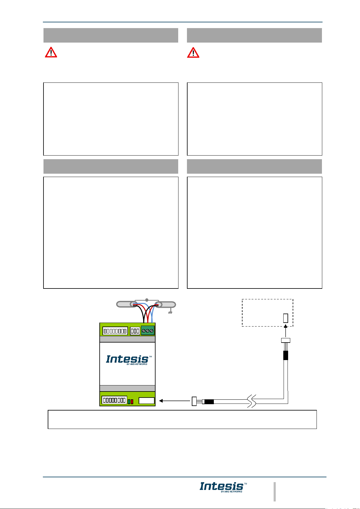
• Desconecte el sistema Fujitsu de la red eléctrica.
• Fije el interfaz a la pared junto a la unidad interior
del aire acondicionado siguiendo las instrucciones del
diagrama de abajo (respete las instrucciones de
seguridad anteriores).
• Conecte el extremo largo del cable suministrado al
conector CN65 de la unidad interior de AA y el otro
extremo al conector AC Unit de la pasarela Intesis.
• Conecte el bus EIA485 al conector EIA485 de la
interfaz.
• Tape la unidad interior del aire acondicionado y
vuelva a conectarlo a la red eléctrica.
• Siga las instrucciones del manual de usuario para la
configuración y puesta en servicio del interfaz.
• Siga las instrucciones de la página siguiente para
configurar la interfaz a través de los Micro
Interruptores.
Instrucciones de instalación
Installation instructions
• Disconnect the Fujitsu system from Mains Power.
• Fix the interface beside the AC indoor unit (wall
mounting) following the instructions in the diagram
below (respect the safety instructions given above).
• Connect the long end of the supplied cable in the
CN65 connector of the AC indoor unit and the other
end into the “AC Unit” connector of our gateway.
• Connect the EIA485 bus to the connector EIA485 of
the interface.
• Close the AC indoor unit and reconnect it to Mains
Power.
• Follow the instructions on the user manual for
configuring and commissioning the interface.
• Follow the instructions of the next page to configure
the interface through on-board DIP-switches.
WARNING
ATENCIÓN
Siga atentamente estas instrucciones de seguridad e
instalación. Un manejo inadecuado puede ocasionar daños
graves para su salud y daños irreparables en el interfaz
y/o en la unidad interna del aire acondicionado.
Follow carefully this safety and installation instructions.
Improper work may lead to serious harmful for your
health and also may damage seriously the interface and/or
the AC indoor unit.
Conexión de la malla
Shield connection
ModBus RTU
EIA-485
Bus
© HMS Industrial Networks S.L.U - All rights reserved
This information is subject to change without notice
URL
https://www.intesis.com
Interfaz INMBSFGL001I000
Interface INMBSFGL001I000
2 / 2
Doc. r1.0
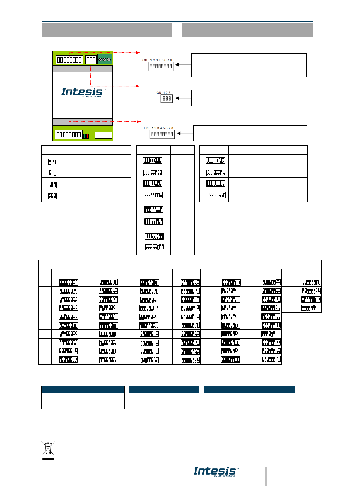
SW3-P1..3
Descripción
Description
SW1-P6..8
Descripción
Description
SW2-P7..8
Descripción
Description
EIA485 bus without termination resistor. The
gateway is not at one end of the EIA485 bus
(valor por defecto - default value)
ON
2400bps
ON
Temperature values in ModBus register are represented
in degrees (x1)
(valor por defecto - default value)
ON
120 Ω termination resistor active. The gateway
is at one end of the EIA485 bus
ON
4800bps
ON
Temperature values in ModBus register are represented
in tenths of degrees (x10)
ON
No bus polarization
(valor por defecto - default value)
ON
9600bps
(valor por defecto
default value)
ON
Temperature values in ModBus register are represented
in Celsius degrees
(valor por defecto - default value)
ON
Bus polarization active
ON …
ON
Temperature values in ModBus register are represented
in Fahrenheit degrees
ON
38400bps
ON
57600bps
ON
76800bps
ON
115200bps
Dirección de esclavo ModBus- ModBus slave address
Direc.
Add
SW2-P1..6
Direc.
Add
SW2-P1..6
Direc.
Add
SW2-P1..6
Direc.
Add
SW2-P1..6
Direc.
Add
SW2-P1..6
Direc.
Add
SW2-P1..6
Direc.
Add
SW2-P1..6
0
ON
10
ON
20
ON
30
ON
40
ON
50
ON
60
ON 1 ON
11
ON
21
ON
31
ON
41
ON
51
ON
61
ON 2 ON
12
ON
22
ON
32
ON
42
ON
52
ON
62
ON 3 ON
13
ON
23
ON
33
ON
43
ON
53
ON
63
ON
4
ON
14
ON
24
ON
34
ON
44
ON
54
ON 5 ON
15
ON
25
ON
35
ON
45
ON
55
ON 6 ON
16
ON
26
ON
36
ON
46
ON
56
ON 7 ON
17
ON
27
ON
37
ON
47
ON
57
ON
8
ON
18
ON
28
ON
38
ON
48
ON
58
ON
9
ON
19
ON
29
ON
39
ON
49
ON
59
ON
LED – Información porporcionada por los LEDs – LED information
LED
Comportamiento
Behaviour
Descripción
Description
LED
Comportamiento
Behaviour
Descripción
Description
LED
Comportamiento
Behaviour
Descripción
Description
L1
(green)
Blinking
0,5s ON / 0,5s OFF
AC Error
L2
(red)
Pulse
3s ON / -s OFF
Under voltage
L1 + L2
Pulse
5s ON / -s OFF
Device start-up
Flashing
0,1s ON / 1,9s OFF
Communication OK
Alternatively
blinking
0,5s ON / 0,5s OFF
EEPROM failure
NOTA: Para más información acerca de otros modos de operación de los leds consulte el manual.
NOTE: Check the manual for more information about other LED operation modes.
ON
Dirección ModBus slave, escala (ºC/ºF) y magnitud (x1/x10) de
temperatura
ModBus slave address, temperature magnitude (ºC/ºF) and scale
(x1/x10)
SW2
AC Unit
B A SG
EIA485
Configuración por Micro Interruptores
This marking on the product, accessories, packaging or literature (manual) indicates that the product contains electronic
parts and they must be properly disposed of by following the instructions at https://intesis.com/weee-regulation
Configuration through DIP - switches
Configuración del dispositivo y ModBus baudrate
Device settings and ModBus baudrate configuration
SW1
Polarización y resistencia de terminación
Polarization and termination resistor
SW3
El Manual de Usuario está disponible en - The User’s Manual is available at:
https://intesis.com/products/ac-interfaces/fujitsu-gateway/fujitsu-modbus-fj-ac-mbs-1
 Loading...