

Page 1
Compatible with AC units, of most AC brands, provided with an IR receiver
Application’s Program version: 1.1
USER MANUAL
Issue date: 02/2020 r1.3 ENGLISH
Page 2

Intesis
TM
KNX – IR Universal AC
User's manual r1.3 EN
© HMS Industrial Networks S.L.U. - All rights reserved
This information is subject to change without notice
URL https://www.intesis.com
2 / 46
Important User Information
Disclaimer
The information in this document is for informational purposes only. Please inform HMS Industrial Networks of
any inaccuracies or omissions found in this document. HMS Industrial Networks disclaims any responsibility or
liability for any errors that may appear in this document.
HMS Industrial Networks reserves the right to modify its products in line with its policy of continuous product
development. The information in this document shall therefore not be construed as a commitment on the part
of HMS Industrial Networks and is subject to change without notice. HMS Industrial Networks makes no
commitment to update or keep current the information in this document.
The data, examples and illustrations found in this document are included for illustrative purposes and are only
intended to help improve understanding of the functionality and handling of the product. In view of the wide
range of possible applications of the product, and because of the many variables and requirements associated
with any particular implementation, HMS Industrial Networks cannot assume responsibility or liability for actual
use based on the data, examples or illustrations included in this document nor for any damages incurred during
installation of the product. Those responsible for the use of the product must acquire sufficient knowledge in
order to ensure that the product is used correctly in their specific application and that the application meets all
performance and safety requirements including any applicable laws, regulations, codes and standards. Further,
HMS Industrial Networks will under no circumstances assume liability or responsibility for any problems that
may arise as a result from the use of undocumented features or functional side effects found outside the
documented scope of the product. The effects caused by any direct or indirect use of such aspects of the product
are undefined and may include e.g. compatibility issues and stability issues.
Page 3

Intesis
TM
KNX – IR Universal AC
User's manual r1.3 EN
© HMS Industrial Networks S.L.U. - All rights reserved
This information is subject to change without notice
URL https://www.intesis.com
3 / 46
Gateway for integration of IR air conditioners into KNX TP-1
(EIB) control systems.
Compatible with AC units, of most AC brands, provided with an IR receiver.
Application’s Program Version: 1.1
ORDER CODE
LEGACY ORDER CODE
INKNXUNI001I000
IS-IR-KNX-1I
Page 4

Intesis
TM
KNX – IR Universal AC
User's manual r1.3 EN
© HMS Industrial Networks S.L.U. - All rights reserved
This information is subject to change without notice
URL https://www.intesis.com
4 / 46
Table of Contents
1 Presentation ............................................................................................................................................ 6
2 Quick setup .............................................................................................................................................. 7
3 Device Installation ................................................................................................................................... 8
Location selection ............................................................................................................................... 8
Connection to IR and location ............................................................................................................ 9
Connection of the device: KNX and USB connection ...................................................................... 11
3.3.1 KNX port connection .............................................................................................................. 11
3.3.2 USB port connection .............................................................................................................. 11
Binary Input connection .................................................................................................................... 12
4 Configuration and setup ........................................................................................................................ 14
5 ETS Parameters and Configuration ...................................................................................................... 15
General configuration ....................................................................................................................... 16
5.1.1 Manual configuration: AC brand and model ........................................................................... 16
5.1.2 Automatic configuration: Auto Learn ...................................................................................... 16
5.1.3 Delay before sending initial “Read” telegrams ....................................................................... 17
5.1.4 Scene to execute on bus recovery / startup........................................................................... 17
5.1.5 Enable “lock control” objects .................................................................................................. 18
5.1.6 Enable func “Operation time objects” ..................................................................................... 18
5.1.7 RGB LED mode ..................................................................................................................... 18
5.1.8 Error notification ..................................................................................................................... 19
AC supported features ..................................................................................................................... 19
Mode ................................................................................................................................................. 19
5.3.1 Enable use of bit-type Mode objects (for control) .................................................................. 20
5.3.2 Enable use of bit-type Mode objects (for status).................................................................... 20
5.3.3 Enable use of + / - object for Mode ........................................................................................ 21
5.3.4 Enable use of Text object for Mode ....................................................................................... 21
Fan Speed ........................................................................................................................................ 21
5.4.1 DPT object type for fan speed ............................................................................................... 22
5.4.2 Enable use of bit-type Fan Speed objects (for Control) ......................................................... 22
5.4.3 Enable use of bit-type Fan Speed objects (for Status) .......................................................... 23
5.4.4 Enable use of +/- object for Fan Speed ................................................................................. 23
5.4.5 Enable use of Text object for Fan Speed ............................................................................... 24
Up-Down vanes configuration dialog ............................................................................................... 24
5.5.1 DPT object type for Vane Up-Down ....................................................................................... 24
5.5.2 Enable use of bit-type Vane U-D objects (for Control) ........................................................... 25
5.5.3 Enable use of bit-type Vane U-D objects (for Status) ............................................................ 25
5.5.4 Enable use of +/- obj for Vane Up-Down ............................................................................... 26
5.5.5 Enable use of Text object for Vane U-D ................................................................................ 26
Left-Right vanes configuration dialog ............................................................................................... 26
5.6.1 DPT object type for Vane Left-Right ...................................................................................... 26
5.6.2 Enable use of bit-type Vane L-R objects (for Control) ........................................................... 27
5.6.3 Enable use of bit-type Vane U-D objects (for Status) ............................................................ 28
5.6.4 Enable use of +/- obj for Vane Left-Right ............................................................................... 28
5.6.5 Enable use of Text object for Vane U-D ................................................................................ 29
Temperature configuration dialog..................................................................................................... 29
5.7.1 Set Point - Enable use of +/- obj for Setp Temp .................................................................... 29
5.7.2 Set Point - Enable limits on Control_ Setpoint obj ................................................................. 30
5.7.3 Set Point - Periodic sending time ........................................................................................... 30
5.7.4 Ambient - Transmission of “Status_ Intesis Ref Temp” ......................................................... 30
5.7.5 Ambient - Periodic sending time ............................................................................................ 30
Scene Configuration dialog .............................................................................................................. 31
5.8.1 Enable use of scenes ............................................................................................................. 31
5.8.2 Scenes can be saved from KNX ............................................................................................ 31
5.8.3 Enable use of bit-field objects for save .................................................................................. 32
5.8.4 Enable use of bit-field objects for execute ............................................................................. 32
5.8.5 Scene “x” preset ..................................................................................................................... 32
Enable use of Open Window ............................................................................................................ 33
Enable use of Occupancy function ............................................................................................. 35
Page 5

Intesis
TM
KNX – IR Universal AC
User's manual r1.3 EN
© HMS Industrial Networks S.L.U. - All rights reserved
This information is subject to change without notice
URL https://www.intesis.com
5 / 46
Binary Input “x” configuration dialogs ......................................................................................... 36
5.11.1 Enable use of Input “x” ........................................................................................................... 37
5.11.2 Contact type ........................................................................................................................... 37
5.11.3 Debounce time ....................................................................................................................... 37
5.11.4 Disabling function ................................................................................................................... 37
5.11.5 Function.................................................................................................................................. 37
6 Electrical and Mechanical features ........................................................................................................ 39
7 List of compatible AC indoor units. ........................................................................................................ 40
8 Appendix A – Communication Objects Table ........................................................................................ 41
Page 6
Intesis
TM
KNX – IR Universal AC
User's manual r1.3 EN
© HMS Industrial Networks S.L.U. - All rights reserved
This information is subject to change without notice
URL https://www.intesis.com
6 / 46
1 Presentation
IntesisTM INKNXUNI001I000 allows monitoring and control of Air Conditioners
from KNX installations.
Compatible with most AC units with an IR receiver.
Great flexibility of integration into your KNX projects. Configuration is made directly from ETS, the
database of the device comes with a complete set of communication objects allowing, from a simple
and quick integration using the basic objects, allowing a simple and quick integration.
Main features:
• Reduced dimensions and quick installation.
• Includes a mini USB connector for fast programming download.
• Multiple objects for control and status (bit, byte, characters…) with KNX standard datapoint types.
• Status objects for every control available.
• Special Modes available (Power, Economy, Additional Heating and Additional Cooling).
• Timeout for Open Window and Occupancy. Sleep function also available.
• Control of the AC unit based in the ambient temperature read by the own AC unit, or in the ambient
temperature read by any KNX thermostat.
• Total Control and Monitoring of the AC unit from KNX, including monitoring of AC unit’s state of internal
variables, running hours’ counter (for filter maintenance control).
• AC unit can be controlled simultaneously by the remote controller of the AC unit and by KNX.
• Up to 5 scenes can be saved and executed from KNX, fixing the desired combination of Operation Mode,
Set Temperature, Fan Speed, Vane Position and Remote Controller Lock in any moment by using a
simple switching.
• Two binary inputs for potential-free contacts provide the possibility to integrate many types of external
devices for window status control (window contacts) and occupancy (presence sensor
Page 7

Intesis
TM
KNX – IR Universal AC
User's manual r1.3 EN
© HMS Industrial Networks S.L.U. - All rights reserved
This information is subject to change without notice
URL https://www.intesis.com
7 / 46
2 Quick setup
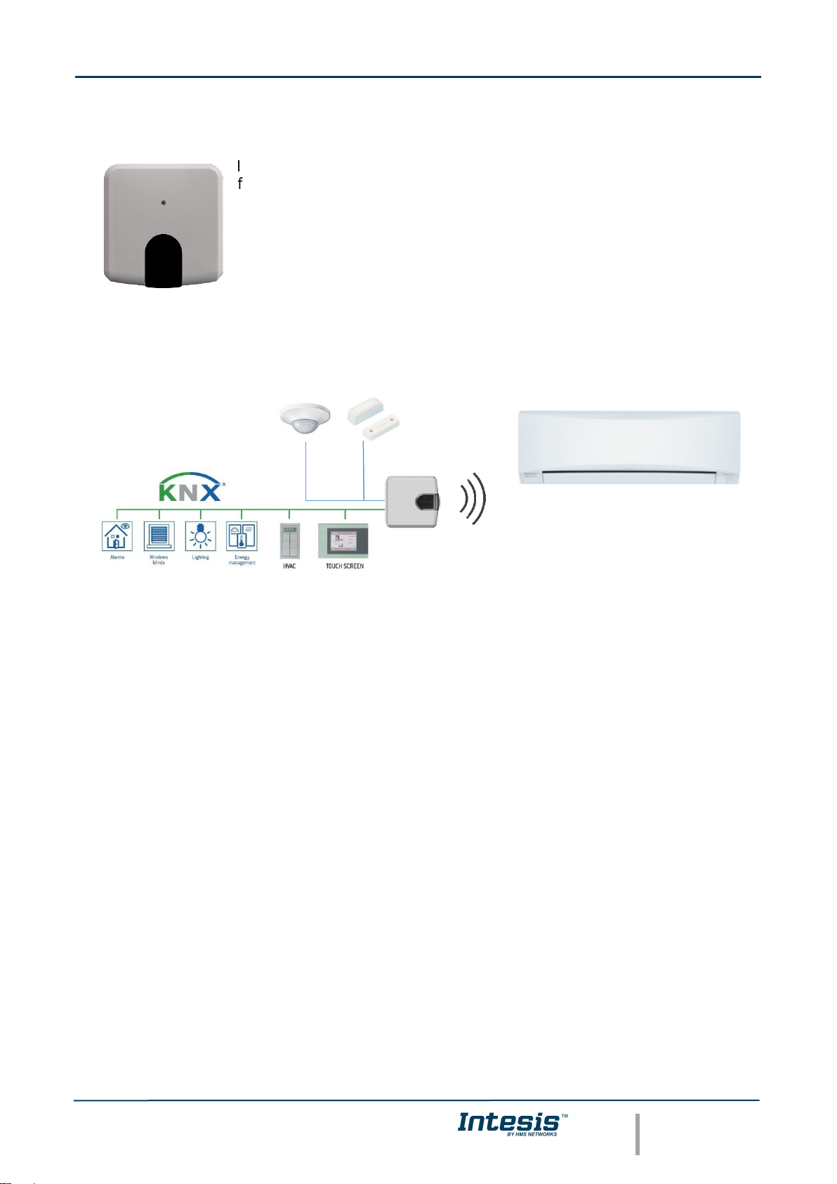
Figure 2.1 INKNXUNI001I000 integration example
1. Check the interface location that best fits the installation (More at 3.1 LOCATION SELECTION)
2. Connect the interface to the KNX bus.
3. Download the ETS database for this product, import it and add it to the current ETS project.
4. Access the parameter section of the Intesis device. Notice that parameters for this interface are
configured through a specific plugin (5 ETS PARAMETERS AND CONFIGURATION).
5. Select the communication objects to be used and other parameters. This step can be omitted if working
with the default objects and parameters.
6. Save the configuration file and download the application program.
7. Close the plugin and apply changes when asked.
8. Link the group address from the communication object of the KNX device with the communication object
inside the Intesis interface.
9. Download the ETS parameters as with any other standard KNX device.
Page 8
Intesis
TM
KNX – IR Universal AC
User's manual r1.3 EN
© HMS Industrial Networks S.L.U. - All rights reserved
This information is subject to change without notice
URL https://www.intesis.com
8 / 46
3 Device Installation
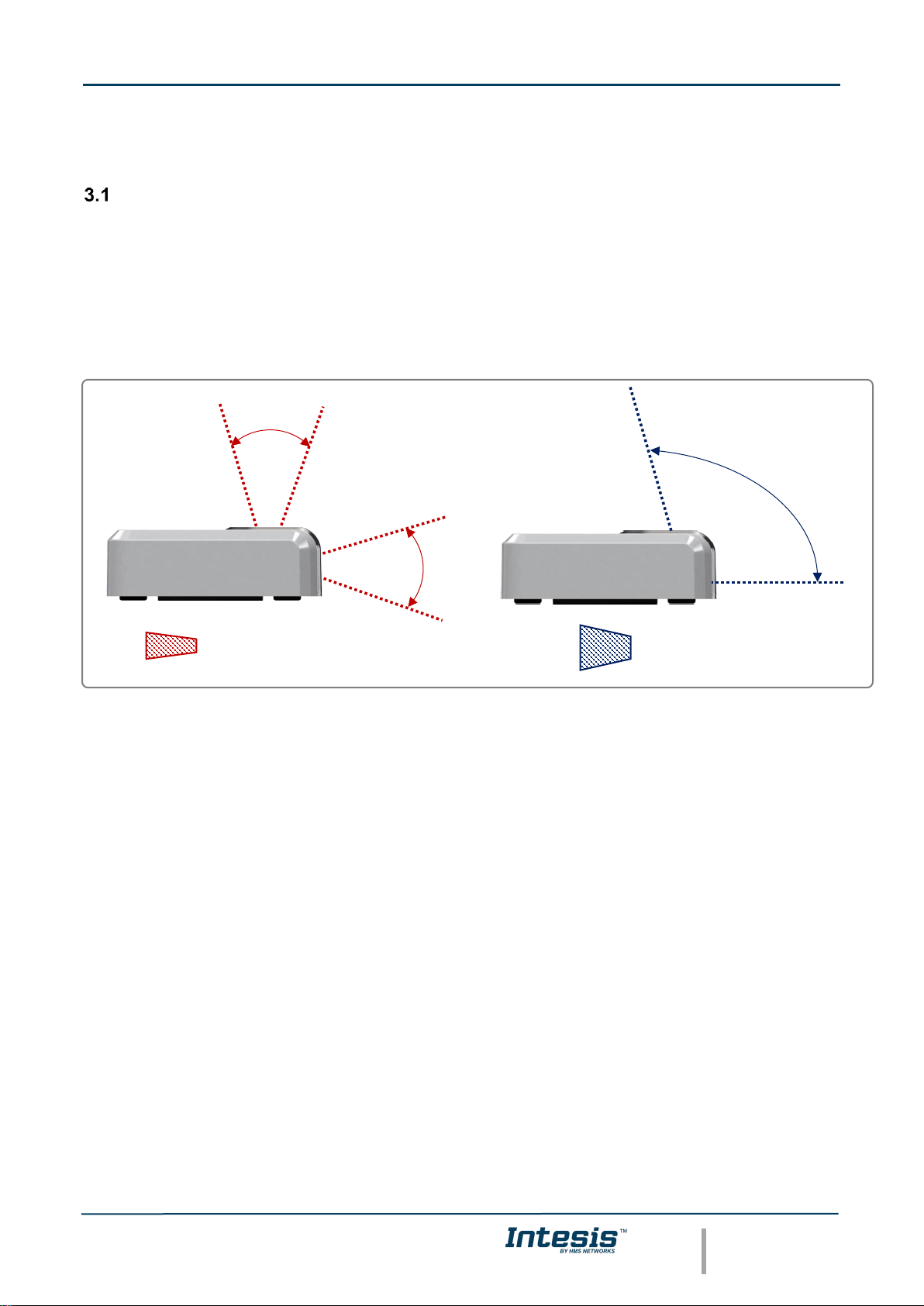
Location selection
Determining that the Intesis device will be working as expected in the installation location is an important stage.
To determine the best location for your Intesis device, use the Wireless Controller (the one of your AC unit).
When selecting the installation location, please keep in mind that the Intesis device has 2 IR emitters and 1 IR
receiver. The 2 emitters increase the installation possibilities allowing many different suitable positions for the
device location. On the other hand, the receiver offers the possibility to get the feedback from the IR wireless
remote controller so the KNX status objects can be updated with that feedback.
Figure 3.1 IR emitters and IR receiver location
IR reception area
IR transmission area
Page 9
Intesis
TM
KNX – IR Universal AC
User's manual r1.3 EN
© HMS Industrial Networks S.L.U. - All rights reserved
This information is subject to change without notice
URL https://www.intesis.com
9 / 46
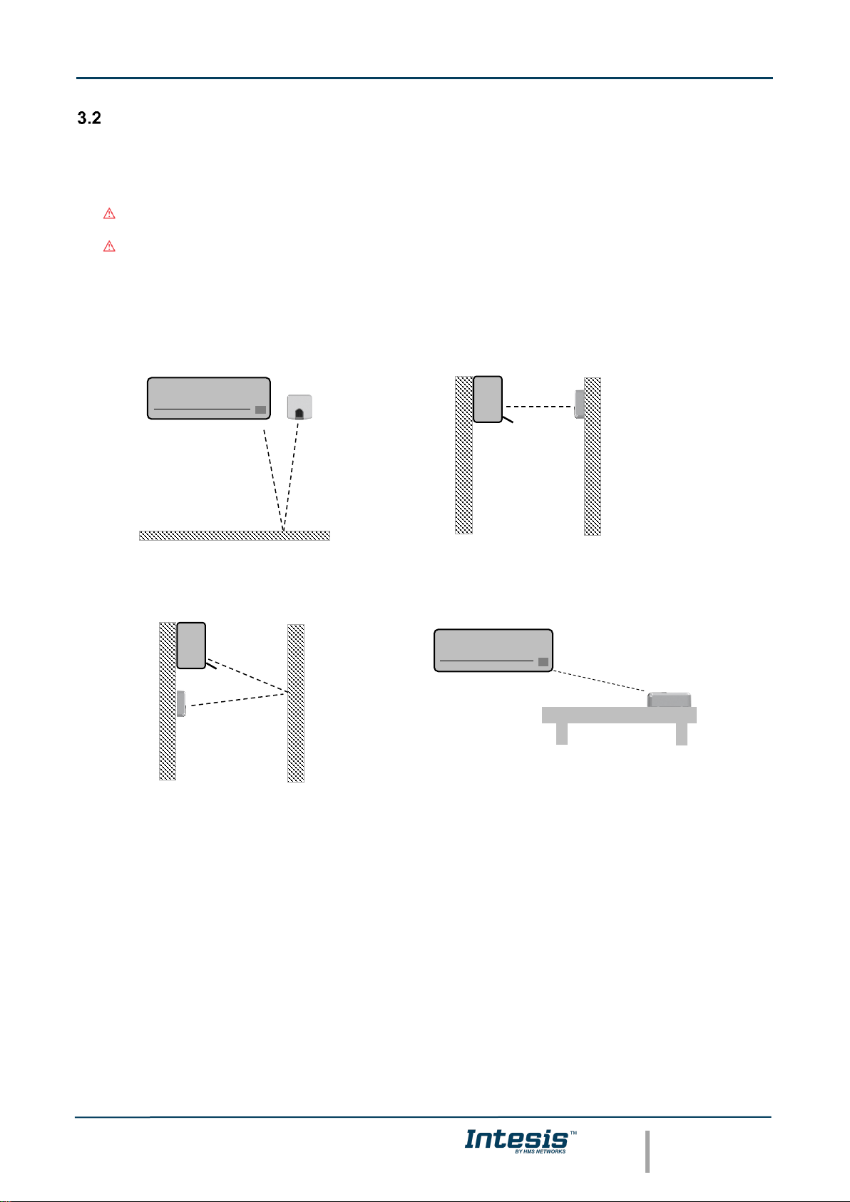
Connection to IR and location
There is no special requirement to match the IR receiver and the Intesis INKNXUNI001I000 interface. Simply
select your model from the list present in the plugin. If your AC unit is not present, please check the compatibility
list as in section 7. You can find more information about the IR configuration in section 5.
Important: Keep in mind that some furniture and materials (carpets, curtains, glass, metal…) may affect
to the IR communication.
Important: The Intesis device has 2 IR emitters pointing at 2 different locations. Considering this and
IR reflections, valid locations for the Intesis device may be many and very different depending on each
installation. Check section 3.1 LOCATION SELECTION for more information.
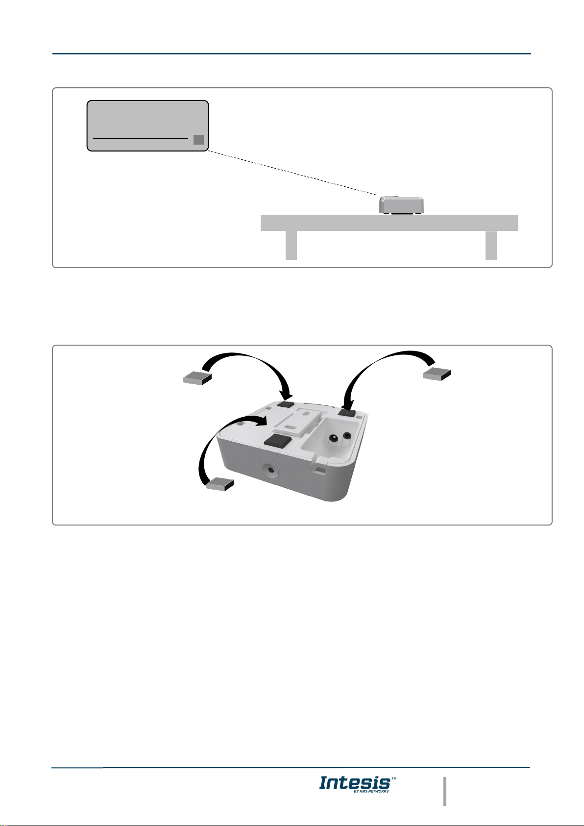
Intesis INKNXUNI001I000 can be installed in many different locations.
A) Side-by-side with the AC unit B) In front of the AC unit
C) Under the AC unit D) Desktop position
Figure 3.2 IR emitters and IR receiver location
Case A: Installed side-by-side with the AC unit. In that case, the signal will travel from the Intesis device to the
AC unit tacking advantage of the rebounds on the floor or other furniture present in the room.
Case B: Installed in front of the AC unit. In that case, the signal will travel from the Intesis device directly to the
AC unit.
Case C: Installed below the AC unit. In that case, the signal will travel from the Intesis device to the AC unit
tacking advantage of the rebounds on the wall in front of it or other furniture present in the room.
Case D: If you want to place the device on your desktop or any other horizontal surface, please consider the
sketch below. In this case, the signal will travel directly from the Intesis device to the AC unit.
Page 10
Intesis
TM
KNX – IR Universal AC
User's manual r1.3 EN
© HMS Industrial Networks S.L.U. - All rights reserved
This information is subject to change without notice
URL https://www.intesis.com
10 / 46
Figure 3.3 Desktop mounted position
In order not to produce marks or scratches on the surface and to improve the device stability, you can use the
rubber dumpers included in the package. Please, check Figure 3.4.
Figure 3.4 Rubber dumpers location
Page 11
Intesis
TM
KNX – IR Universal AC
User's manual r1.3 EN
© HMS Industrial Networks S.L.U. - All rights reserved
This information is subject to change without notice
URL https://www.intesis.com
11 / 46
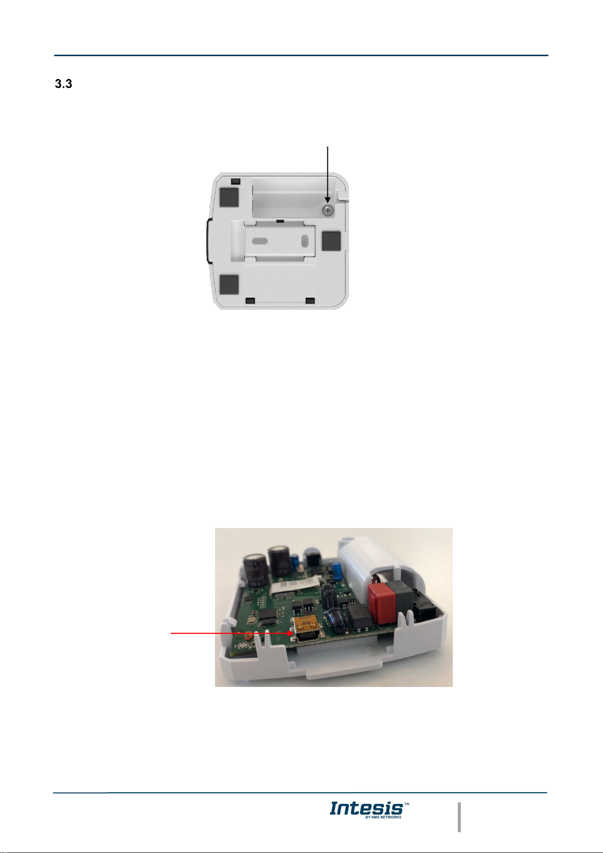
Connection of the device: KNX and USB connection
To get access to the KNX or mini USB connector, remove the screw as seen in Figure 3.5.
Figure 3.5 Top lid release and KNX connection
3.3.1 KNX port connection
Intesis device needs to be connected directly through a KNX TP-1 bus.
Disconnect power of the KNX bus. Connect the INKNXUNI001I000 to the KNX TP-1 (EIB) bus using the KNX
standard connector (red/grey) of the INKNXUNI001I000, respect polarity.
Reconnect power of the KNX bus, and mains power of the AC unit.
3.3.2 USB port connection
Intesis device allows a USB connection via mini USB port for the IR remote parameters or application program
version download. Please, refer to 4 CONFIGURATION AND SETUP for further information.
Figure 3.8 USB port connector
Make sure the device is not connected to power (KNX or USB) during the connection of the USB port.
Setscrew
USB port
Page 12
Intesis
TM
KNX – IR Universal AC
User's manual r1.3 EN
© HMS Industrial Networks S.L.U. - All rights reserved
This information is subject to change without notice
URL https://www.intesis.com
12 / 46
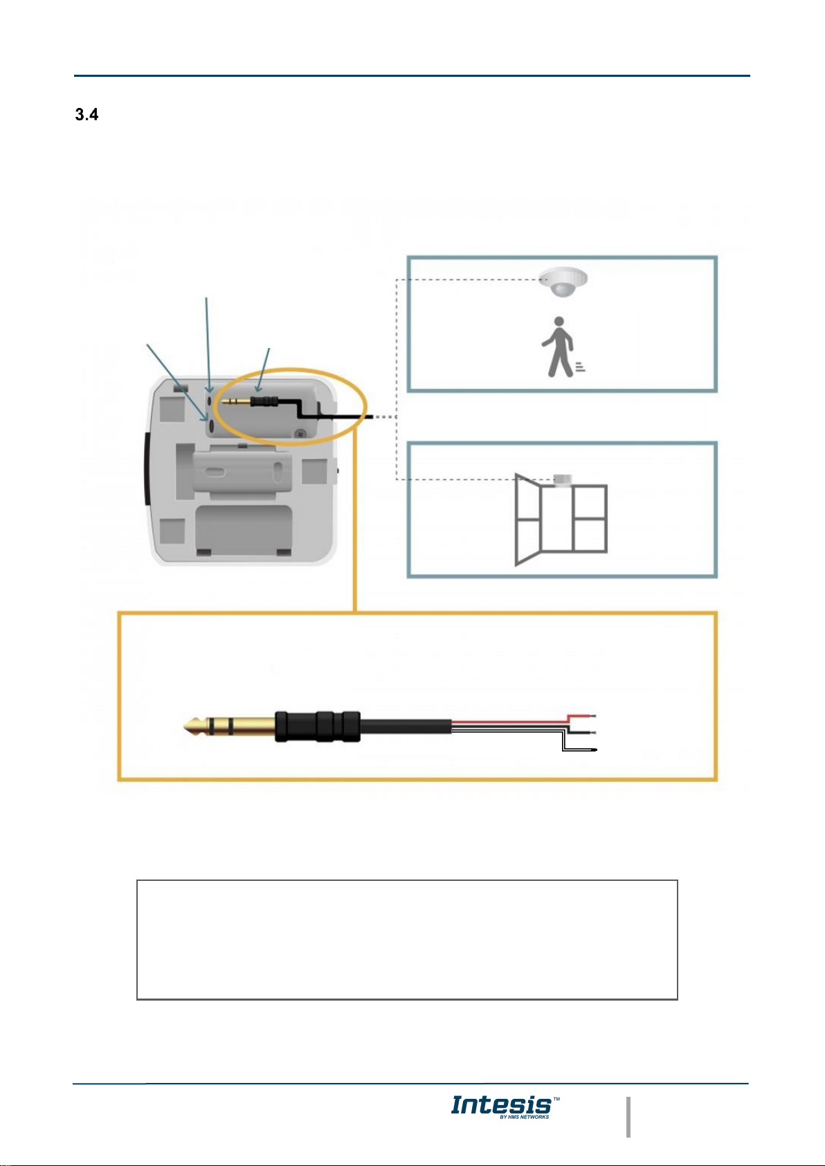
Binary Input connection
Intesis INKNXUNI001I000 interface is equipped with Binary Inputs from factory. To use the built-in binary inputs
in all the IR KNX Controllers, a standard 3,5mm stereo jack connector is required.
Connections will be as in the image below.
Figure 3.7 Binary Input connection
Before proceeding, please check the technical specification of the binary input below:
Once you are sure your installation is compliant with the specifications, please check the presence sensor or
window contact you would like to use. Basically, sensors only need to be equipped with a potential free external
CHANNEL 1: PRESENCE DETECTOR
CHANNEL 2: WINDOW CONTACT
STEREO JACK
(3,5 mm)
BINARY INPUT
CONNECTOR
KNX INPUT
CONNECTOR
CHANNEL 1
COMMON
CHANNEL 2
Potential free binary input
Signal cable length: 5m unshielded, may be extended up to 20m with twisted
Compliant with the following standards:
IEC61000-4-2: level 4 – 15kV (air discharge) - 8kV (contact discharge)
MIL STD 883E-Method 3015-7: class 3B
Page 13

Intesis
TM
KNX – IR Universal AC
User's manual r1.3 EN
© HMS Industrial Networks S.L.U. - All rights reserved
This information is subject to change without notice
URL https://www.intesis.com
13 / 46
contact. No matter if the contact is NO (Normally Open) or NC (Normally closed) as you will be able to configure
the contact type (NO or NC) of your sensor in the settings of the Binary Input function (Go to Settings menu in
the Intesis WEB Site).
IMPORTANT NOTE: Please, note that INKNXUNI001I000 interface will only react if the contact of your sensor
is opened or closed. In the case of the presence sensor, the installer needs to decide the specific settings of
the presence sensor to be applied. Intesis will be not responsible of the incorrect settings or incorrect
installations.
Recommendation: In some presence sensors or window contacts it is possible to setup a delay time to the
external contact. As you will see in this manual, Intesis Settings allow the user to setup a timer before starting
with the configured actions. Anyway, we recommend to setup a certain delay time in your presence sensor or
window contact to prevent continuous contact changes in a very short period of time.
Page 14

Intesis
TM
KNX – IR Universal AC
User's manual r1.3 EN
© HMS Industrial Networks S.L.U. - All rights reserved
This information is subject to change without notice
URL https://www.intesis.com
14 / 46
4 Configuration and setup
This is a fully compatible KNX device which must be configured and setup using standard KNX tool ETS.
Before starting with the configuration, please make sure that the binary inputs (if used) and the USB cable are
properly connected to the interface. Make sure as well, that the interface is connected to the KNX bus to allow
the proper download of the KNX programming.
To proceed with the configuration and setup, it is recommended to follow instructions next:
1. Download and install the latest version of the ETS data base (5 ETS Parameters and Configuration).
2. Open the product’s plugin.
3. Select your AC brand and model.
4. Download the infrared configuration to the Intesis pushing on the “Download IR parameters”.
NOTE: Check the current connection to the Intesis. Notice that to send the Infrared configuration, you
can use the standard KNX connection (the same used to program the device) or a USB connection. For
this purpose, a mini USB port is available by opening the device.
USB connection is faster than KNX connection. Notice that USB is only available for the IR
parameters download (see 5.1 General configuration).
5. Proceed with the rest of AC unit settings and other parameters in the plugin tab.
6. Finish the KNX programming: communication object links and device addressing.
7. Download the configuration to the device as usual KNX device.
Page 15

Intesis
TM
KNX – IR Universal AC
User's manual r1.3 EN
© HMS Industrial Networks S.L.U. - All rights reserved
This information is subject to change without notice
URL https://www.intesis.com
15 / 46
5 ETS Parameters and Configuration
The Intesis INKNXUNI001I000 interface is configured through ETS. General KNX parameters, such as the
physical address, group addresses or DPTs can be configured as usual using the ETS interface. For the specific
AC unit configuration and IR communication, the use of the specific plugin included in the ETS database is
required.
ETS database for this device can be downloaded from:
https://www.intesis.com/products/ac-interfaces/knx-gateways/universal-knx-ir-is-ir-knx-1
Please consult the README.txt file, located inside the downloaded zip file, to find instructions on how to install
the database.
Once the database is imported, the plugin can be accessed when editing parameters. To get access to
parameters edition, click on the Parameter tab, located in the project screen, and then press the specific
parameter dialog.
Figure 5.1 ETS Project managing and plugin screen
Remember that before start using the Intesis interface along with the AC unit, you need to set up at least the
brand and type of you AC unit. Check section 5.1 for more information about it.
Important: Please, update the Catalogue before proceeding with the device configuration and
programming. The laptop where ETS is running shall have Internet connection to update the catalogue.
Page 16

Intesis
TM
KNX – IR Universal AC
User's manual r1.3 EN
© HMS Industrial Networks S.L.U. - All rights reserved
This information is subject to change without notice
URL https://www.intesis.com
16 / 46
General configuration
The main view of this tab is the showed in the next figure. Parameter description will follow next:
Figure 5.2 General parameters
Configuration of the AC model
There are two possibilities to configure the AC model to control through INKNXUNI001I000: doing a manual
configuration, by including the AC brand and unit model, or doing an automatic configuration, by using Auto
Learn. To use the last option, it is mandatory the IR remote controller of the AC unit.
5.1.1 Manual configuration: AC brand and model
Use the dropdown menus to select the brand and model of the AC unit to control.
In case your AC unit brand or model were not available in the list, please select the INKNXUNI001I000 and
contact our support department for more information about the settings to select.
5.1.2 Automatic configuration: Auto Learn
The auto learn function is available for INKNXUNI001I000 using 1.1 application program version or newer. This
function allows to identify the infrared remote control automatically by only sending a command pointing to the
KNX device. Please note that internet connection is required for this function.
To launch the function, press the button “Auto Learn” and follow the instructions given in the pop-up window:
AC brand
AC unit model
Page 17

Intesis
TM
KNX – IR Universal AC
User's manual r1.3 EN
© HMS Industrial Networks S.L.U. - All rights reserved
This information is subject to change without notice
URL https://www.intesis.com
17 / 46
Once clicked on “Receive IR frame”, the following sequence will be executed:
1) The device will be prepared to receive the frame. During this period (up to 10s) no frame from IR
remote is expected and the device LED is OFF (sometimes a short red blink may be noticed).
2) Once the LED changes into steady white, the device is ready to receive the IR frame and a 30s
countdown will start. Kindly consider the following advices to do it in the proper way:
a. It is necessary to press ON/OFF once and wait for about 5s to let the device transmitting the
information to the PC. You can notice this transmission if the countdown freezes.
b. If ON/OFF button is pressed many times, the process may be enlarged till the user stops, as
the frame communication will not be the appropriate.
3) If the process finishes properly, the LED will switch OFF and a pop-up will be displayed with the
message "Frame Received". If the remote is available in the database, the remote will appear in
"Discovered RCF's" being highly recommended to use the "recomended remote" to match with the
integration needed.
In case the remote is not available in the database, you will get a pop-up warning with the following
message: "Frame could not be recognized". In this case, please, contact to our Support Team so that
they will inform you about the next steps.
Both manual or automatic remote configuration options need to press the button “Download IR parameters” to
download the current AC choice over INKNXUNI001I000. Please, make sure the option selected is the desired
one before starting this process as this process may last for some minutes. Refer to 4 ABOVE4 CONFIGURATION
AND SETUP for more information about IR parameter downloads available.
Other settings
5.1.3 Delay before sending initial “Read” telegrams
This parameter sets the delay before the interface will send READ telegrams for the group addresses associated
on its Control_ objects on bus recovery or application reset/start-up. All Control_ objects with both Transmit (T)
and Update (U) flags enabled will send READs and their values will be updated with the response when
received.
Valid values go from 10 to 60 seconds. This is to give time enough to other KNX devices on the bus to start-up
before sending the READs.
5.1.4 Scene to execute on bus recovery / startup
This parameter executes a selected scene on bus recovery or startup, only if the selected scene has an enabled
preset or values previously saved from KNX bus (see Scene Configuration dialog). You can select any of the 5
available scenes.
Page 18

Intesis
TM
KNX – IR Universal AC
User's manual r1.3 EN
© HMS Industrial Networks S.L.U. - All rights reserved
This information is subject to change without notice
URL https://www.intesis.com
18 / 46
5.1.5 Enable “lock control” objects
This parameter shows/hide the Control_ Lock Control Obj communication object which, depending on the sent
value, locks or unlocks ALL the Control_ communication objects except itself.
When a “1” value is sent to this communication object, the remote controller is locked. To be unlocked a “0”
value must be sent. The gateway remembers the last value received even if a KNX bus reset/failure happens.
Figure 5.3 Communication object detail
Important: If an initial scene is enabled and it has as Value for Remote Lock (unchanged) or unlocked,
this would unlock the remote controller because the initial scene has priority over the Control_ Lock Remote
Control communication object.
5.1.6 Enable func “Operation time objects”
This parameter shows/hides the Status_ Operating Hour Counter and Status_ Operating Second Counter
communication object which counts the number of operating hours for the INKNXUNI001I000.
Figure 5.4 Communication object detail
o If set to “no” the object will not be shown.
o If set to “yes” the Status_ Operation Hour Counter object will appear.
• This object can be read and sends its status every time an hour is counted. The gateway keeps that
count in memory and the status is sent also after a KNX bus reset/failure. Although this object is
marked as a Status_ object it also can be written to update the counter when needed. To reset the
counter should be written a “0” value.
Important: This object comes by default without the write (W) flag activated. If is necessary to write on it, this
flag must be activated.
Important: This object will also return its status, every time a value is written, only if it’s different from the
existing one.
Important: If the stored value is 0 hours, the gateway will not send the status to KNX.
5.1.7 RGB LED mode
This parameter determines the working mode of the interface LED.
o If set to “Always off” the LED will always be off.
o If set to “Always on” the LED will always be on.
o If set to “Only on changes” the LED will always change when there is a change of value in any of the
active communication objects.
Page 19

Intesis
TM
KNX – IR Universal AC
User's manual r1.3 EN
© HMS Industrial Networks S.L.U. - All rights reserved
This information is subject to change without notice
URL https://www.intesis.com
19 / 46
5.1.8 Error notification
This device uses three different error communication objects to report any issue of the device itself. These
errors are not related to the AC errors since the device do not receive information from the AC unit.
The 1-bit error notification object Status_ Error/Alarm is 1 when any error is active and 0 when no errors are
detected.
The 2 bytes error object Status_ Error Code reports the error code while the 14 bytes error object Status_ Error
Text code reports the information about the error code.
The information about the internal errors reported is the following:
Error code
(2 bytes)
Text code
(14 bytes object)
How to solve
-1
COMM ERROR
Open plug-in and Download IR parameters again
-3
WRONG IR-FW1
Open plug-in and Download IR parameters again
-4
WRONG IR-FW2
Open plug-in and Download IR parameters again
-5
#0005
Restart device
-200
SUPPLY2 FAIL
Device is not receiving enough supply
AC supported features
Select the AC features of your AC unit to match both: the AC unit features with the enabled communication
objects and parameters.
Please, select these parameters carefully, otherwise not expected behavior may occur.
Figure 5.5 AC supported features
Mode
All the parameters in this section are related with the different mode properties and communication objects.
Page 20

Intesis
TM
KNX – IR Universal AC
User's manual r1.3 EN
© HMS Industrial Networks S.L.U. - All rights reserved
This information is subject to change without notice
URL https://www.intesis.com
20 / 46
The byte-type communication object for Mode works with the DTP_20.105. Auto mode will be enabled with a
“0” value, Heat mode with a “1” value, Cool mode with a “3” value, Fan mode with a “9” value and Dry mode
with a “14” value.
Figure 5.6 AC mode additional communication objects
5.3.1 Enable use of bit-type Mode objects (for control)
This parameter shows/hides the bit-type Control_ Mode objects.
Figure 5.7 Communication object detail
o If set to “no” the objects will not be shown.
o If set to “yes” the Control_ Mode objects for Auto, Heat, Cool, Fan and Dry will appear. To activate a
mode by using these objects a “1” value has to be sent.
5.3.2 Enable use of bit-type Mode objects (for status)
This parameter shows/hides the bit-type Status_ Mode objects.
Figure 5.8 Communication object detail
o If set to “no” the objects will not be shown.
o If set to “yes” the Status_ Mode objects for Auto, Heat, Cool, Fan and Dry will appear. When enabled,
a mode will return a “1” through its bit-type object.
Page 21

Intesis
TM
KNX – IR Universal AC
User's manual r1.3 EN
© HMS Industrial Networks S.L.U. - All rights reserved
This information is subject to change without notice
URL https://www.intesis.com
21 / 46
5.3.3 Enable use of + / - object for Mode
This parameter shows/hides the Control_ Mode +/- communication object which lets change the indoor unit
mode by using two different datapoint types.
o If set to “no” the object will not be shown.
o If set to “yes” the Control_ Mode +/- object and a new parameter will appear.
➢ DPT type for +/- Mode Object
This parameter lets choose between the datapoints 0-Up / 1-Down [DPT_1.008] and 0-Decrease / 1-
Increase [DPT_1.007] for the Control_ Mode +/- object.
The sequence followed when using this object is shown below:
5.3.4 Enable use of Text object for Mode
This parameter shows/hides the Status_ Mode Text communication object.
o If set to “no” the object will not be shown.
o If set to “yes” the Status_ Mode Text object will appear.
Fan Speed
All the parameters in this section are related with the Fan Speed properties and communication objects.
Figure 5.9 Fan Speed parameters
▪ Up / Increase
▪ Down / Decrease
DRY
AUTO
HEAT
COOL
FAN
Page 22

Intesis
TM
KNX – IR Universal AC
User's manual r1.3 EN
© HMS Industrial Networks S.L.U. - All rights reserved
This information is subject to change without notice
URL https://www.intesis.com
22 / 46
5.4.1 DPT object type for fan speed
With this parameter is possible to change de DPT for the Control_ Fan Speed and Status_ Fan Speed bytetype communication objects. Datapoints Scaling (DPT_5.001) and Enumerated (DPT_5.010) can be selected.
o When “Enumerated [DPT 5.010]” is selected, Control_ Fan Speed and Status_ Fan Speed communication
objects for this DPT will appear. Also, depending on the number of fan speeds selected, these objects will
be different.
The first fan speed will be selected if a “1” is sent to the Control_ object. The second fan speed will be
selected sending a “2” and so on.
The Status_ object will always return the value for the fan speed selected.
Important: In both cases if a “0” value is sent to the Control_ object, the minimum fan speed will be
selected. If a value bigger than “2” (in case of 2 speeds) or bigger than “3” (in case of 3 fan speeds)
is sent to the Control_ object, then the maximum fan speed will be selected.
o When “Scaling [DPT 5.001]” is selected, Control_ Fan Speed and Status_ Fan Speed communication
objects for this DPT will appear. Also, depending on the number of fan speeds selected, these objects will
be different.
The formula used to calculate the value to be set in the Control object is ‘100*(n+0,5)/N %’, where n is the
current fan speed and N the maximum number of fan speeds.
On the other hand, the formula to calculate the status to be read according to the current value is ‘100*n/N’,
where n is the current fan speed and N the maximum number of fan speeds.
Check this example with 3 fan speeds:
When a value between 0% and 49% is sent to the Control_ object the first fan speed will be selected.
When a value between 50% and 83% is sent to the Control_ object, the second speed will be selected.
When a value between 84% and 100% is sent to the Control_ object, the third speed will be selected.
The Status_ object will return a 33% when the first speed is selected, a 67% for the second one and a 100%
for the third one.
5.4.2 Enable use of bit-type Fan Speed objects (for Control)
This parameter shows/hides the bit-type Control_ Fan Speed objects.
Fan Speed 1
Fan Speed 3
100%
Status_
0%
83%
50%
Control_
Control_
Status_
33%
67%
Fan Speed 2
Control_
Status_
Page 23

Intesis
TM
KNX – IR Universal AC
User's manual r1.3 EN
© HMS Industrial Networks S.L.U. - All rights reserved
This information is subject to change without notice
URL https://www.intesis.com
23 / 46
o If set to “no” the objects will not be shown.
o If set to “yes” the Control_ Fan Speed objects for Speed 1, Speed 2 and Speed 3 (if available) will
appear. To activate a Fan Speed by using these objects a “1” value has to be sent.
5.4.3 Enable use of bit-type Fan Speed objects (for Status)
This parameter shows/hides the bit-type Status_ Fan Speed objects.
o If set to “no” the objects will not be shown.
o If set to “yes” the Status_ Fan Speed objects for Speed 1, Speed 2 and Speed 3 (if available) will
appear. When a Fan Speed is enabled, a “1” value is returned through its bit-type object.
5.4.4 Enable use of +/- object for Fan Speed
This parameter shows/hides the Control_ Fan Speed +/- communication object which lets you
increase/decrease the indoor unit fan speed by using two different datapoint types.
o If set to “no” the object will not be shown.
o If set to “yes” the Control_ Fan Speed +/- object.
➢ DPT type for +/- Fan Speed Object
This parameter lets choose between the datapoints 0-Up / 1-Down [DPT_1.008] and 0-Decrease / 1-
Increase [DPT_1.007] for the Control_ Fan Speed +/- object.
➢ Roll-over Speed at upper/lower limit
This parameter lets choose if roll-over will be enabled (“yes”) or disabled (“no”) for the Control_ Fan
Speed +/- object.
Fan Speed 3
Fan Speed 1
Fan Speed 2
Only if Roll-over is enabled
Only if Roll-over is enabled
Page 24

Intesis
TM
KNX – IR Universal AC
User's manual r1.3 EN
© HMS Industrial Networks S.L.U. - All rights reserved
This information is subject to change without notice
URL https://www.intesis.com
24 / 46
5.4.5 Enable use of Text object for Fan Speed
This parameter shows/hides the Status_ Fan Speed Text communication object.
o If set to “no” the object will not be shown.
o If set to “yes” the Status_ Fan Speed Text object will appear.
Up-Down vanes configuration dialog
All the parameters in this section are related with the Vane Up-Down properties and communication objects.
5.5.1 DPT object type for Vane Up-Down
With this parameter is possible to change de DPT for the Control_ Vane Up-Down and Status_ Vane Up-Down
byte-type communication objects. Datapoints Scaling (DPT_5.001) and Enumerated (DPT_5.010) can be
selected.
o When “Enumerated [DPT 5.010]” is selected, Control_ Vane Up-Down and Status_ Vane Up-Down
communication objects for this DPT will appear.
To choose a vane position, values from “1” to “N” can be sent to the Control_ object. Each value will
correspond to the position (i.e. Value “3” = Position 3).
The Status_ object will always return the value for the vane position selected.
Important: If a “0” value is sent to the Control_ object, the Position 1 will be selected. If a value bigger
than “N” is sent to the Control_ object, then the Position N will be selected.
o When “Scaling [DPT 5.001]” is selected, Control_ Vane Up-Down and Status_ Vane Up-Down
communication objects for this DPT will appear.
The formula used to calculate the value to be set in the Control object is ‘100*(n+0,5)/N %’, where n is the
current fan speed and N the maximum number of fan speeds.
On the other hand, the formula to calculate the status to be read according to the current value is ‘100*n/N’,
where n is the current fan speed and N the maximum number of fan speeds.
Check the example with 5 positions:
When a value between 0% and 29% is sent to the Control_ object the first vane position will be selected.
▪ Up / Increase
▪ Down / Decrease
Page 25

Intesis
TM
KNX – IR Universal AC
User's manual r1.3 EN
© HMS Industrial Networks S.L.U. - All rights reserved
This information is subject to change without notice
URL https://www.intesis.com
25 / 46
When a value between 30% and 49% is sent to the Control_ object, the second vane position will be
selected.
When a value between 50% and 69% is sent to the Control_ object, the third vane position will be selected.
When a value between 70% and 89% is sent to the Control_ object, the fourth vane position will be selected.
When a value between 90% and 100% is sent to the Control_ object, the fifth vane position will be selected.
The Status_ object will return a 20% for the first vane position, a 40% for the second one, a 60% for the
third one, an 80% for the fourth one and a 100% for the fifth and last one.
5.5.2 Enable use of bit-type Vane U-D objects (for Control)
This parameter shows/hides the bit-type Control_ Vane Up-Down objects.
o If set to “no” the objects will not be shown.
o If set to “yes” the Control_ Vane Up-Down objects for each Position (1 to 5) will appear. To activate a
Vane Position by using these objects, a “1” value has to be sent.
5.5.3 Enable use of bit-type Vane U-D objects (for Status)
This parameter shows/hides the bit-type Status_ Vane Up-Down objects.
o If set to “no” the objects will not be shown.
o If set to “yes” the Status_ Vane Up-Down objects for each Position (1 to N) will appear. When a Vane
Position is enabled, a “1” value is returned through its bit-type object.
Pos. 1
Pos. 3
100%
Status_
0%
90%
50%
Control_
Control_
Status_
30%
70%
Pos. 2
Control_
Status_
Pos. 4
Pos. 5
Control_
Control_
20%
40%
60%
80%
Status_
Status_
Page 26

Intesis
TM
KNX – IR Universal AC
User's manual r1.3 EN
© HMS Industrial Networks S.L.U. - All rights reserved
This information is subject to change without notice
URL https://www.intesis.com
26 / 46
5.5.4 Enable use of +/- obj for Vane Up-Down
This parameter shows/hides the Control_ Vane Up-Down +/- communication object which lets you change the
indoor unit vane position by using two different datapoint types.
o If set to “no” the object will not be shown.
o If set to “yes” the Control_ Vane Up-Down +/- object.
➢ DPT type for +/- Vane Up-Down obj
This parameter lets choose between the datapoints 0-Up / 1-Down [DPT_1.008] and 0-Decrease / 1-
Increase [DPT_1.007] for the Control_ Vane Up-Down +/- object.
➢ Rollover Vane at upper/lower limit
This parameter lets choose if roll-over will be enabled (“yes”) or disabled (“no”) for the Vane Up-Down
+/- object.
5.5.5 Enable use of Text object for Vane U-D
This parameter shows/hides the Status_ Vane Up-Down Text communication object.
o If set to “no” the object will not be shown.
o If set to “yes” the Status_ Vane Up-Down Text object will appear.
Left-Right vanes configuration dialog
All the parameters in this section are related with the Vane Up-Down properties and communication objects.
5.6.1 DPT object type for Vane Left-Right
With this parameter is possible to change de DPT for the Control_ Vane Left-Right and Status_ Vane Left-Right
byte-type communication objects. Datapoints Scaling (DPT_5.001) and Enumerated (DPT_5.010) can be
selected.
o When “Enumerated [DPT 5.010]” is selected, Control_ Vane Left-Right and Status_ Vane Left-Right
communication objects for this DPT will appear.
▪ Up / Increase
▪ Down / Decrease
Pos. 3
Pos. 1
Pos. 2
Only if Roll-over is enabled
Only if Roll-over is enabled
Pos. 5
Pos. 4
SWING
Page 27

Intesis
TM
KNX – IR Universal AC
User's manual r1.3 EN
© HMS Industrial Networks S.L.U. - All rights reserved
This information is subject to change without notice
URL https://www.intesis.com
27 / 46
To choose a vane position, values from “1” to “N” can be sent to the Control_ object. Each value will
correspond to the position (i.e. Value “3” = Position 3).
The Status_ object will always return the value for the vane position selected.
Important: If a “0” value is sent to the Control_ object, the Position 1 will be selected. If a value bigger
than “N” is sent to the Control_ object, then the Position N will be selected.
o When “Scaling [DPT 5.001]” is selected, Control_ Vane Up-Down and Status_ Vane Up-Down
communication objects for this DPT will appear.
The formula used to calculate the value to be set in the Control object is ‘100*(n+0,5)/N %’, where n is the
current fan speed and N the maximum number of fan speeds.
On the other hand, the formula to calculate the status to be read according to the current value is ‘100*n/N’,
where n is the current fan speed and N the maximum number of fan speeds.
Check the example with 5 positions:
When a value between 0% and 29% is sent to the Control_ object the first vane position will be selected.
When a value between 30% and 49% is sent to the Control_ object, the second vane position will be
selected.
When a value between 50% and 69% is sent to the Control_ object, the third vane position will be selected.
When a value between 70% and 89% is sent to the Control_ object, the fourth vane position will be selected.
When a value between 90% and 100% is sent to the Control_ object, the fifth vane position will be selected.
The Status_ object will return a 20% for the first vane position, a 40% for the second one, a 60% for the
third one, an 80% for the fourth one and a 100% for the fifth and last one.
5.6.2 Enable use of bit-type Vane L-R objects (for Control)
This parameter shows/hides the bit-type Control_ Vane Left-Right objects.
Pos. 1
Pos. 3
100%
Status_
0%
90%
50%
Control_
Control_
Status_
30%
70%
Pos. 2
Control_
Status_
Pos. 4
Pos. 5
Control_
Control_
20%
40%
60%
80%
Status_
Status_
Page 28

Intesis
TM
KNX – IR Universal AC
User's manual r1.3 EN
© HMS Industrial Networks S.L.U. - All rights reserved
This information is subject to change without notice
URL https://www.intesis.com
28 / 46
o If set to “no” the objects will not be shown.
o If set to “yes” the Control_ Vane Up-Down objects for each Position (1 to N) will appear. To activate a
Vane Position by using these objects, a “1” value has to be sent.
5.6.3 Enable use of bit-type Vane U-D objects (for Status)
This parameter shows/hides the bit-type Status_ Vane Up-Down objects.
o If set to “no” the objects will not be shown.
o If set to “yes” the Status_ Vane Up-Down objects for each Position (1 to N) will appear. When a Vane
Position is enabled, a “1” value is returned through its bit-type object.
5.6.4 Enable use of +/- obj for Vane Left-Right
This parameter shows/hides the Control_ Vane Left-Right +/- communication object which lets you change the
indoor unit vane position by using two different datapoint types.
o If set to “no” the object will not be shown.
o If set to “yes” the Control_ Vane Left-Right +/- object.
➢ DPT type for +/- Vane Left-Right obj
This parameter lets choose between the datapoints 0-Up / 1-Down [DPT_1.008] and 0-Decrease / 1-
Increase [DPT_1.007] for the Control_ Vane Left-Right +/- object.
➢ Rollover Vane at upper/lower limit
This parameter lets choose if roll-over will be enabled (“yes”) or disabled (“no”) for the Vane Up-Down
+/- object.
Pos. 3
Pos. 1
Pos. 2
Only if Roll-over is enabled
Only if Roll-over is enabled
Pos. 5
Pos. 4
SWING
Page 29

Intesis
TM
KNX – IR Universal AC
User's manual r1.3 EN
© HMS Industrial Networks S.L.U. - All rights reserved
This information is subject to change without notice
URL https://www.intesis.com
29 / 46
5.6.5 Enable use of Text object for Vane U-D
This parameter shows/hides the Status_ Vane Up-Down Text communication object.
o If set to “no” the object will not be shown.
o If set to “yes” the Status_ Vane Up-Down Text object will appear.
Temperature configuration dialog
All the parameters in this section are related with the Temperature properties and communication objects.
Figure 5.10 Tempeature settings
5.7.1 Set Point - Enable use of +/- obj for Setp Temp
This parameter shows/hides the Control_ Setpoint Temp +/- communication object which lets you change the
indoor unit setpoint temperature by using two different datapoint types.
o If set to “no” the object will not be shown.
o If set to “yes” the Control_ Setpoint Temp +/- object.
➢ DPT type for +/- Setp Temp object
▪ Up / Increase
▪ Down / Decrease
Page 30

Intesis
TM
KNX – IR Universal AC
User's manual r1.3 EN
© HMS Industrial Networks S.L.U. - All rights reserved
This information is subject to change without notice
URL https://www.intesis.com
30 / 46
This parameter lets choose between the datapoints 0-Up / 1-Down [DPT_1.008] and 0-Decrease / 1Increase [DPT_1.007] for the Control_ Setpoint Temp +/- object.
5.7.2 Set Point - Enable limits on Control_ Setpoint obj
This parameter enables to define temperature limits for the Control_ Setpoint Temperature object.
o If set to “no” the setpoint temperature limits for the Control_ Setpoint Temperature object will be the
default: 16ºC for the lower limit and 32ºC for the upper limit.
o If set to “yes” it is possible to define temperature limits for the Control_ Setpoint Temperature object.
➢ Control_ Set Temp Lower limit (ºC)
This parameter lets to define the lower limit for the setpoint temperature.
➢ Control_ Set Temp Upper limit (ºC)
This parameter lets to define the upper limit for the setpoint temperature.
Important: If a setpoint temperature above the upper defined limit (or below the lower defined limit) is sent
through the Control_ Setpoint Temperature object, it will be ALWAYS applied the limit defined.
Important: When limits are enabled, any setpoint temperature sent to the AC (even through scenes, special
modes, etc.) will be limited.
5.7.3 Set Point - Periodic sending time
This parameter lets you change the interval of time (in seconds, from 0 to 255) at the end of which the AC
setpoint temperature is sent to the KNX bus. For a “0” value, the AC setpoint temperature will ONLY be sent
on change. The AC setpoint temperature is sent through the communication object Status_ AC Setpoint Temp.
5.7.4 Ambient - Transmission of “Status_ Intesis Ref Temp”
This parameter lets to you choose if the Intesis reference temperature will be sent “only cyclically”, “only on
change” or “cyclically and on change”. The Intesis reference temperature is sent through the communication
object Status_ Intesis Reference Temperature.
5.7.5 Ambient - Periodic sending time
This parameter will only be available for the “only cylically” and “cyclically and on change” options, and lets
you change the interval of time (in seconds, from 1 to 255) at the end of which the Intesis reference temperature
is sent to the KNX bus.
▪ Up / Increase
▪ Down / Decrease
…
16ºC
17ºC
32ºC
31ºC
(Upper limit)
(Lower limit)
Page 31

Intesis
TM
KNX – IR Universal AC
User's manual r1.3 EN
© HMS Industrial Networks S.L.U. - All rights reserved
This information is subject to change without notice
URL https://www.intesis.com
31 / 46
Scene Configuration dialog
All the parameters in this section are related with the Scene properties and communication objects. A scene
contains values of: On/Off, Mode, Fan speed, Vane position and Setpoint Temperature.
Figure 5.11 Scene configuration settings
5.8.1 Enable use of scenes
This parameter shows/hides the scene configuration parameters and communication objects.
o If set to “no” the scene parameters and communication objects will not be shown.
o If set to “yes” the scene parameters and communication objects will be shown. To execute a scene
through the byte-type object, a value from “0” to “4” has to be sent, correponding each one to a different
scene (i.e. “0” = Scene 1;… “4” = Scene 5).
5.8.2 Scenes can be saved from KNX
This parameter shows/hides the Control_ Save/Exec Scene and all the Control_ Save Scene (if enabled)
communication objects.
Page 32

Intesis
TM
KNX – IR Universal AC
User's manual r1.3 EN
© HMS Industrial Networks S.L.U. - All rights reserved
This information is subject to change without notice
URL https://www.intesis.com
32 / 46
o If set to “no” the communication objects will not be shown.
o If set to “yes” the communication objects and a new parameter will appear. To store a scene through
the byte-type object, a value from “128” to “132” has to be sent to the object, correponding each one
to a different scene (i.e. “128” = Scene 1;… “132” = Scene 5).
➢ Enable use of bit objects for storing scenes (from bus)
If set to “no” the objects will not be shown.
If set to “yes” the Control_ Store Scene objects for storing scenes will appear. To store a scene by
using these objects, a “1” value has to be sent to the scene’s object we want to store (i.e. to store scene
4, a “1” has to be sent to the Control_ Store Scene 4 object).
5.8.3 Enable use of bit-field objects for save
This parameter shows/hides the Control_ Execute Scene bit-type communication objects.
o If set to “no” the communication objects will not be shown.
o If set to “yes” the communication objects will appear. To execute a scene by using these objects, a
“1” value has to be sent to the scene’s object we want to execute (i.e. to execute scene 4, a “1” has to
be sent to the Control_ Execute Scene 4 object).
5.8.4 Enable use of bit-field objects for execute
This parameter shows/hides the Control_ Execute Scene bit-type communication objects.
o If set to “no” the communication objects will not be shown.
o If set to “yes” the communication objects will appear. To execute a scene by using these objects, a
“1” value has to be sent to the scene’s object we want to execute (i.e. to execute scene 4, a “1” has to
be sent to the Control_ Execute Scene 4 object).
5.8.5 Scene “x” preset
This parameter lets you define a preset for a scene (the following description is valid for all the scenes).
o If set to “no” the preset for the scene “x” will be disabled.
Page 33

Intesis
TM
KNX – IR Universal AC
User's manual r1.3 EN
© HMS Industrial Networks S.L.U. - All rights reserved
This information is subject to change without notice
URL https://www.intesis.com
33 / 46
o If set to “yes” the preset will be enabled. When a scene is executed the values configured in the preset
will be aplied.
Important: If a scene’s preset is enabled, will not be possible to modify (store) the scene from the KNX
bus.
➢ Scene “x” / Value for On-Off
This parameter lets you choose the power of the indoor unit when the scene is executed. The following
options are available: “ON”, “OFF” or “(unchanged)”.
➢ Scene “x” / Value for Mode
This parameter lets you choose the mode of the indoor unit when the scene is executed. The following
options are available: “AUTO”, “HEAT”, “COOL”, “FAN”, “DRY”, or “(unchanged)”.
➢ Scene “x” / Value for Fan Speed
This parameter lets you choose the fan speed of the indoor unit when the scene is executed. The
following options are available: “SPEED 1”, “SPEED 2”… “SPEED N”, or “(unchanged)”.
➢ Scene “x” / Value for Vane Up-Down
This parameter lets you choose the vane position of the indoor unit when the scene is executed. The
following options are available: “POSITION 1”, “POSITION 2”… “POSITION N”, “SWIRL”, “SWING”
or “(unchanged)”.
➢ Scene “x” / Value for Vane Left-Right
This parameter lets you choose the vane position of the indoor unit when the scene is executed. The
following options are available: “POSITION 1”, “POSITION 2”… “POSITION N”, “SWIRL”, “SWING”
or “(unchanged)”.
➢ Scene “x” / Value for Setp Temp (ºC)
This parameter lets you choose the setpoint temperature of the indoor unit when the scene is executed.
The following options are available: from “16ºC” to “32ºC” (both included), or “(unchanged)”.
Important: If any preset value is configured as “(unchanged)”, the execution of this scene will not
change current status of this feature in the AC unit.
Important: When a scene is executed, Status_ Current Scene object shows the number of this scene.
Any change in previous items does Status_ Current Scene show “No Scene”. Only changes on items
marked as “(unchanged)” will not disable current scene.
Enable use of Open Window
This parameter shows/hides the Control_ Window Contact Input communication object which lets you Start/Stop
a timeout to switch off the indoor unit.
Page 34

Intesis
TM
KNX – IR Universal AC
User's manual r1.3 EN
© HMS Industrial Networks S.L.U. - All rights reserved
This information is subject to change without notice
URL https://www.intesis.com
34 / 46
o If set to “no” the object will not be shown.
o If set to “yes” the Control_ Window Contact Input object will appear. If a “1” value is sent to this object,
and the indoor unit is already turned on, the switch-off timeout will begin. If a “0” value is sent to this
object, the switch-off timeout will stop.
➢ Input Object
This parameter lets you choose between the datapoints 0-Open / 1-Closed Window [DPT_1.009] and
0-Stop / 1-Start Timeout [DPT_1.010] for the Control_ Switch Off Timeout.
➢ Timeout (min)
This parameter lets you select how much time (in minutes) to wait before switching off the indoor unit.
➢ Reload last Value
If set to “no”, once the switch-off timeout is stopped, any value will be reloaded.
If set to “yes”, once the switch-off timeout is stopped, the last On/Off value sent will be reloaded.
• If a “1” value is sent to the Control_ Window Contact Input object after the timeout period, the
indoor unit will turn on.
• If a “0” value is sent to the Control_ Switch Off Timeout after the timeout period, no action will
be performed.
➢ Lock ON when Open
If set to “no”, On/Off commands while the window is open will be accepted.
• If a “1” value is sent to the Control_ Switch Off Timeout object the switch-off timeout period will
begin again.
• If a “0” value is sent to the Control_ Switch Off Timeout object, no action will be performed.
If set to “yes”, On/Off commands, while the window is open, will be saved (but not applied). These
commands will be used in the next parameter if set to “yes”.
Page 35

Intesis
TM
KNX – IR Universal AC
User's manual r1.3 EN
© HMS Industrial Networks S.L.U. - All rights reserved
This information is subject to change without notice
URL https://www.intesis.com
35 / 46
Enable use of Occupancy function
This parameter shows/hides the Control_ Occupancy Input communication object which lets you apply different
parameters to the indoor unit depending on the presence/no presence in the room.
o If set to “no” the object will not be shown.
o If set to “yes” the Control_ Occupancy object and new parameters will appear. If a “1” value is sent to
this object (no room occupancy), the timeout will begin. If a “0” value is sent to this object, the timeout
will stop.
➢ Timeout to apply action (minutes)
This parameter lets you choose how much time to wait (in minutes) before executing the action specified
in the next parameter (“Action after timeout elapsed”).
➢ Action
When Switch Off AC is selected, once the timeout has elapsed, the indoor unit will be turned off.
When Apply Preset Delta is selected, once the timeout has elapsed, a delta temperature will be applied
to save energy (decreasing the setpoint when in Heat mode or increasing the setpoint when in Cool
mode). Also new parameters will appear.
➢ Temp delta decreases (HEAT) or increase (COOL) (ºC)
This parameter lets configure the delta temperature (increase or decrease) that will be applied
when the timeout has elapsed.
Important: When there is occupancy again after the application of a delta, the same delta will be applied
inversely. (i.e. In a room with AC in cool mode and 25ºC setpoint temperature, a +2ºC delta is applied
after the occupancy timeout, setting the setpoint at 27ºC because there is no occupancy in the room. If
Page 36

Intesis
TM
KNX – IR Universal AC
User's manual r1.3 EN
© HMS Industrial Networks S.L.U. - All rights reserved
This information is subject to change without notice
URL https://www.intesis.com
36 / 46
the setpoint is raised to 29ºC during that period, when the room is occupied again, a -2ºC delta will be
applied and the final setpoint temperature will then be 27ºC).
➢ Second Action
If set to “no” nothing will be applied.
If set to “yes”, a new timeout will be enabled, and two new parameters will appear.
➢ Timeout (2nd)
This parameter lets you choose how much time to wait (in minutes) before executing the action specified
in the next parameter (“Action after timeout elapsed”).
➢ Action (2nd)
When Switch-Off is selected, once the timeout has elapsed, the indoor unit will turn off.
When Apply Preset Delta is selected, once the timeout configured is extinguished, a delta temperature
will be applied (decreasing the setpoint when in Heat mode or increasing the setpoint when in Cool
mode). Also new parameters will appear.
➢ Temp delta decreases (HEAT) or increase (COOL) (ºC)
This parameter lets configure the delta temperature that will be applied when the timeout is
extinguished.
Important: When there is occupancy again after the application of a delta, the same delta will
be applied inversely as explained above.
➢ Reload last On/Off value when Occupied
If set to “no”, once the switch-off timeout has elapsed, any value will be reloaded.
If set to “yes”, once the switch-off timeout has elapsed, the last On/Off value will be reloaded.
• If a “1” value is sent to the Control_ Occupancy object after the timeout period, the indoor unit
will turn on.
• If a “0” value is sent to the Control_ Occupancy after the timeout period no action will be
performed.
➢ Lock ON when occupied
If set to “no”, On/Off commands while the room is occupied will be accepted.
• If a “1” value is sent to the Control_ Switch Off Timeout object the switch-off timeout period will
begin again.
• If a “0” value is sent to the Control_ Switch Off Timeout object, no action will be performed.
If set to “yes”, On/Off commands, while the window is open, will be saved (but not applied). These
commands will be used in the next parameter if set to “yes”.
Binary Input “x” configuration dialogs
All the parameters in this section are related with the binary inputs properties and communication objects.
Page 37

Intesis
TM
KNX – IR Universal AC
User's manual r1.3 EN
© HMS Industrial Networks S.L.U. - All rights reserved
This information is subject to change without notice
URL https://www.intesis.com
37 / 46
5.11.1 Enable use of Input “x”
This parameter enables the use of the Input “x”.
o If set to “no” the objects will not be shown.
o If set to “yes” the Status_ Inx object(s) and new parameters will appear.
5.11.2 Contact type
This parameter lets choose the behavior that will have the binary input depending on if the contact is normally
open or normally closed.
o There are two possible options to configure the contact type: “NO: Normally Open” and “NC:
Normally Closed”.
5.11.3 Debounce time
This parameter lets choose a debounce time (in milliseconds) that will be applied to the contact.
5.11.4 Disabling function
This parameter shows/hides the Control_ Disable Input x communication object which will let disable/enable the
input x.
o If set to “no” any object will be shown.
o When “DPT 1.003: 0-Disable; 1-Enable” is selected, the input can be disabled using the value “0”
and enabled using the value “1”.
o When “DPT 1.002: 1-True (Disable); 0-False (Enable)” is selected, the input can be disabled using
the value “1” and enabled using the value “0”.
5.11.5 Function
This parameter lets choose the function that will have the binary input. There are 3 different functions available:
Occupancy (internal), On/Off and Window Contact (internal).
Page 38

Intesis
TM
KNX – IR Universal AC
User's manual r1.3 EN
© HMS Industrial Networks S.L.U. - All rights reserved
This information is subject to change without notice
URL https://www.intesis.com
38 / 46
o When “Occupancy” is selected, the binary input “x” will have the same behavior as configured in the
parameter “Occupanys” (section 5.10).
o When “On/Off” is selected, the AC unit will turn off when the binary inpyt “x” is active.
o When “Window Contact (internal)” is selected, the binary input “x” will have the same behavior as
configured in the parameter “Window Contact” (section 5.9).
Page 39

Intesis
TM
KNX – IR Universal AC
User's manual r1.3 EN
© HMS Industrial Networks S.L.U. - All rights reserved
This information is subject to change without notice
URL https://www.intesis.com
39 / 46
6 Electrical and Mechanical features
Enclosure
ABS (V-0). 2,1 mm thickness
PC (V-2). 1 mm thickness
Dimensions
81 x 78 x 28 mm
Weight
76 g
Color
Ivory white
Power supply
29V DC, 17mA
Supplied through KNX bus
Mounting
Wall and desktop
LED indicators
1 x Device status and KNX programming
Push buttons
1 x KNX programming.
Binary inputs
2 x binary inputs for potential-free contacts.
Signal cable length: 5m unshielded, may be extended up to 20m with twisted.
Compliant with the following standards:
IEC61000-4-2: level 4 - 15kV (air discharge) - 8kV (contact discharge)
MIL STD 883E-Method 3015-7: class3B
Console port
Mini USB port for console usage
Configuration
Configuration with ETS
Operating
Temperature
From 0ºC to 40ºC
Operating
humidity
<93% HR, no condensation
Stock humidity
<93% HR, no condensation
27 mm
78 mm
81 mm
28 mm
26 mm
3 mm
Page 40

Intesis
TM
KNX – IR Universal AC
User's manual r1.3 EN
© HMS Industrial Networks S.L.U. - All rights reserved
This information is subject to change without notice
URL https://www.intesis.com
40 / 46
7 List of compatible AC indoor units.
A list of indoor unit model references compatible with INKNXUNI001I000 and their available features can be
found in:
https://www.intesis.com/docs/compatibilities/inxxxuni001i000_universal_compatibility
Page 41

Intesis
TM
KNX – IR Universal AC
User's manual r1.2 eng
© HMS Industrial Networks S.L.U - All rights reserved
This information is subject to change without notice
URL https://www.intesis.com
41 / 46
8 Appendix A – Communication Objects Table
TOPIC
OBJECT
NUMBER
NAME
LENGTH
DATAPOINT TYPE
FLAGS
FUNCTION
DPT_NAME
DPT_ID
R W T
U
CONTROL OBJECTS
On/Off
1
Control_ On/Off
1 bit
DPT_Switch
1.001
W T 0 - Off; 1-On
Mode
2
Control_ Mode
1 byte
DPT_HVACContrMode
20.105
W T 0 - Auto; 1 - Heat; 3 - Cool; 9 - Fan; 14 - Dry
3
Control_ Mode Cool/Heat
1 bit
DPT_Heat/Cool
1.100
W T 0 - Cool; 1 - Heat
4
Control_Mode Cool & On
1 byte
DPT_Scaling
5.001
W T 0 – OFF; 0,1%-100% ON + Cool
5
Control_Mode Heat & On
1 byte
DPT_Scaling
5.001
W T 0 – OFF; 0,1%-100% ON + Heat
6
Control_ Mode Auto
1 bit
DPT_Bool
1.002
W T 1 - Auto
7
Control_ Mode Heat
1 bit
DPT_Bool
1.002
W T 1 - Heat
8
Control_ Mode Cool
1 bit
DPT_Bool
1.002
W T 1 - Cool
9
Control_ Mode Fan
1 bit
DPT_Bool
1.002
W T 1 - Fan
10
Control_ Mode Dry
1 bit
DPT_Bool
1.002
W T 1 - Dry
11
Control_ Mode -/+
1 bit
DPT_Step
1.007
W 0 - Decrease; 1 - Increase
Control_ Mode +/-
1 bit
DPT_UpDown
1.008
W 0 - Up; 1 - Down
Fan Speed
12
Control_ Fan Speed / N Speeds
1 byte
DPT_Scaling
5.001
W T 100*(n+0,5)/N %
Control_ Fan Speed / N Speeds
1 byte
DPT_Enumerated
5.010
W T
1 - Speed1; 2 - Speed2; 3 - Speed3; 4 - Speed4;
5 - Speed5; 6 - Speed6; 7 - Speed7
13
Control_ Fan Speed Man/Auto
1 bit
DPT_Bool
1.002
W T 0 - Manual; 1 - Auto
14
Control_ Fan Speed 1
1 bit
DPT_Bool
1.002
W T 1 - Fan Speed 1
15
Control_ Fan Speed 2
1 bit
DPT_Bool
1.002
W T 1 - Fan Speed 2
16
Control_ Fan Speed 3
1 bit
DPT_Bool
1.002
W T 1 - Fan Speed 3
17
Control_ Fan Speed 4
1 bit
DPT_Bool
1.002
W T 1 - Fan Speed 4
18
Control_ Fan Speed 5
1 bit
DPT_Bool
1.002
W T 1 - Fan Speed 5
Page 42

Intesis
TM
KNX – IR Universal AC
User's manual r1.2 eng
© HMS Industrial Networks S.L.U - All rights reserved
This information is subject to change without notice
URL https://www.intesis.com
42 / 46
19
Control_ Fan Speed 6
1 bit
DPT_Bool
1.002
W T 1 - Fan Speed 6
20
Control_ Fan Speed 7
1 bit
DPT_Bool
1.002
W T 1 - Fan Speed 7
21
Control_ Fan Speed -/+
1 bit
DPT_Step
1.007
W T 0 - Decrease; 1 - Increase
Control_ Fan Speed +/-
1 bit
DPT_UpDown
1.008
W T 0 - Up; 1 - Down
Vanes
22
Control_ Vane Up-Down / N pos
1 byte
DPT_Scaling
5.001
W T 100*(n+0,5)/N %
Control_ Vane Up-Down / N pos
1 byte
DPT_Enumerated
5.010
W T
1 - Pos1; 2 - Pos2; 3 - Pos3; 4 - Pos4; 5 - Pos5;
6 - Pos6; 7 - Pos7; 8 - Pos8
23
Control_ Vane Up-Down Man/Auto
1 bit
DPT_Bool
1.002
W T 0 - Manual; 1 - Auto
24
Control_ Vane Up-Down Pos1
1 bit
DPT_Bool
1.002
W T 1 - Position 1
25
Control_ Vane Up-Down Pos2
1 bit
DPT_Bool
1.002
W T 1 - Position 2
26
Control_ Vane Up-Down Pos3
1 bit
DPT_Bool
1.002
W T 1 - Position 3
27
Control_ Vane Up-Down Pos4
1 bit
DPT_Bool
1.002
W T 1 - Position 4
28
Control_ Vane Up-Down Pos5
1 bit
DPT_Bool
1.002
W T 1 - Position 5
29
Control_ Vane Up-Down Pos6
1 bit
DPT_Bool
1.002
W T 1 - Position 6
30
Control_ Vane Up-Down Pos7
1 bit
DPT_Bool
1.002
W T 1 - Position 7
31
Control_ Vane Up-Down Pos8
1 bit
DPT_Bool
1.002
W T 1 - Position 8
32
Control_ Vane Up-Down Swing
1 bit
DPT_Bool
1.002
W T 0 - Stop; 1 – Swing
33
Control_ Vane Up-Down Swirl
1 bit
DPT_Bool
1.002
W T 0 - Stop; 1 – Swirl
34
Control_ Vane Up-Down Wide
1 bit
DPT_Bool
1.002
W T 0 - Stop; 1 – Wide
35
Control_ Vane Up-Down -/+
1 bit
DPT_Step
1.007
W 0 - Decrease; 1 - Increase
Control_ Vane Up-Down +/-
1 bit
DPT_UpDown
1.008
W 0 - Up; 1 - Down
36
Control_ Vane Up-Down Move Pos
1 bit
DPT_Trigger
1.002
W T 0,1 Move Position
37
Control_ Vane Left-Right / N pos
1 byte
DPT_Scaling
5.001
W T 100*(n+0,5)/N %
Control_ Vane Left-Right / N pos
1 byte
DPT_Enumerated
5.010
W T
1 - Pos1; 2 - Pos2; 3 - Pos3; 4 - Pos4; 5 - Pos5;
6 - Pos6; 7 - Pos7; 8 - Pos8
38
Control_ Vane Left-Right Man/Auto
1 bit
DPT_Bool
1.002
W T 0 - Manual; 1 - Auto
39
Control_ Vane Left-Right Pos1
1 bit
DPT_Bool
1.002
W T 1 - Position 1
40
Control_ Vane Left-Right Pos2
1 bit
DPT_Bool
1.002
W T 1 - Position 2
Page 43

Intesis
TM
KNX – IR Universal AC
User's manual r1.2 eng
© HMS Industrial Networks S.L.U - All rights reserved
This information is subject to change without notice
URL https://www.intesis.com
43 / 46
41
Control_ Vane Left-Right Pos3
1 bit
DPT_Bool
1.002
W T 1 - Position 3
42
Control_ Vane Left-Right Pos4
1 bit
DPT_Bool
1.002
W T 1 - Position 4
43
Control_ Vane Left-Right Pos5
1 bit
DPT_Bool
1.002
W T 1 - Position 5
44
Control_ Vane Left-Right Pos6
1 bit
DPT_Bool
1.002
W T 1 - Position 6
45
Control_ Vane Left-Right Pos7
1 bit
DPT_Bool
1.002
W T 1 - Position 7
46
Control_ Vane Left-Right Pos8
1 bit
DPT_Bool
1.002
W T 1 - Position 8
47
Control_ Vane Left-Right Swing
1 bit
DPT_Bool
1.002
W T 0 - Stop; 1 – Swing
48
Control_ Vane Left-Right Swirl
1 bit
DPT_Bool
1.002
W T 0 - Stop; 1 – Swirl
49
Control_ Vane Left-Right Wide
1 bit
DPT_Bool
1.002
W T 0 - Stop; 1 – Wide
50
Control_ Vane Left-Right +/-
1 bit
DPT_Step
1.007
W 0 - Decrease; 1 – Increase
Control_ Vane Left-Right +/-
1 bit
DPT_UpDown
1.008
W 0 - Up; 1 – Down
51
Control_ Vane Left-Right Move Pos
1 bit
DPT_Trigger
1.002
W T 0,1 Move Position
Temperature
52
Control_ Setpoint Temperature
2 bytes
DPT_Value_Temp
9.001
W T 16ºC to 32ºC
53
Control_ Setpoint Temp -/+
1 bit
DPT_Step
1.007
W 0 - Decrease; 1 – Increase
Control_ Setpoint Temp +/-
1 bit
DPT_UpDown
1.008
W 0 - Up; 1 – Down
54
Control_ Ambient Temperature
2 bytes
DPT_Value_Temp
9.001
W T ºC value
Window
55
Control_ Window Contact Input
1 bit
DPT_Window_Door
1.019
W T 0 - Closed; 1 - Open
Occupancy
56
Control_ Occupancy Input
1 bit
DPT_Occupancy
1.018
W T 0 – Not Occupied; 1 - Occupied
Sleep
57
Control_ Sleep Timeout
1 bit
DPT_start/stop
1.010
W T 0 – Stop; 1 - Start
Locking
58
Control_ Lock Remote Control
1 bit
DPT_Bool
1.002
W T 0 - Unlocked; 1 – Locked
59
Control_ Lock Control Objects
1 bit
DPT_Bool
1.002
W T 0 - Unlocked; 1 – Locked
Operating Time
60
Control_ Operating Hour Counter
2 bytes
DPT_Time (Hours)
7.007
W T Number of operating hours
61
Control_ Operating Second Counter
2 bytes
DPT_Time_Lag (Sec)
13.100
W T Number of operating seconds
Scenes
62
Control_ Save/Exec Scene
1 byte
DPT_SceneControl
18.001
W
0 to 4 - Exec. Scene 1 to 5;
128 to 132 - Save Scene 1 to 5
63
Control_ Store Scene1
1 bit
DPT_Bool
1.002
W 1 - Store Scene
64
Control_ Store Scene2
1 bit
DPT_Bool
1.002
W 1 - Store Scene
Page 44

Intesis
TM
KNX – IR Universal AC
User's manual r1.2 eng
© HMS Industrial Networks S.L.U - All rights reserved
This information is subject to change without notice
URL https://www.intesis.com
44 / 46
65
Control_ Store Scene3
1 bit
DPT_Bool
1.002
W 1 - Store Scene
66
Control_ Store Scene4
1 bit
DPT_Bool
1.002
W 1 - Store Scene
67
Control_ Store Scene5
1 bit
DPT_Bool
1.002
W 1 - Store Scene
68
Control_ Execute Scene1
1 bit
DPT_Bool
1.002
W 1 - Execute Scene
69
Control_ Execute Scene2
1 bit
DPT_Bool
1.002
W 1 - Execute Scene
70
Control_ Execute Scene3
1 bit
DPT_Bool
1.002
W 1 - Execute Scene
71
Control_ Execute Scene4
1 bit
DPT_Bool
1.002
W 1 - Execute Scene
72
Control_ Execute Scene5
1 bit
DPT_Bool
1.002
W 1 - Execute Scene
Disabling
73
Control_ Disable Input 1
1 bit
DPT_Bool
1.002
W T 0 - Enable; 1 - Disable
Control_ Disable Input 1
1 bit
DPT_Enable
1.003
W T 0 - Disable; 1 - Enable
74
Control_ Disable Input 2
1 bit
DPT_Bool
1.002
W T 0 - Enable; 1 - Disable
Control_ Disable Input 2
1 bit
DPT_Enable
1.003
W T 0 - Disable; 1 - Enable
STATUS OBJECTS
On/Off
75
Status_ On/Off
1 bit
DPT_Switch
1.001
R T 0 - Off; 1-On
Mode
76
Status_ Mode
1 byte
DPT_HVACContrMode
20.105
R T 0 - Auto; 1 - Heat; 3 - Cool; 9 - Fan; 14 - Dry
77
Status_ Mode Cool/Heat
1 bit
DPT_Heat/Cool
1.100
R T 0 - Cool; 1 - Heat
78
Status_ Mode Auto
1 bit
DPT_Bool
1.002
R T 1 - Auto
79
Status_ Mode Heat
1 bit
DPT_Bool
1.002
R T 1 - Heat
80
Status_ Mode Cool
1 bit
DPT_Bool
1.002
R T 1 - Cool
81
Status_ Mode Fan
1 bit
DPT_Bool
1.002
R T 1 - Fan
82
Status_ Mode Dry
1 bit
DPT_Bool
1.002
R T 1 - Dry
83
Status_ Mode Text
14 byte
DPT_String_8859_1
16.001
R T ASCII String
Fan Speed
84
Status_ Fan Speed / N Speeds
1 byte
DPT_Scaling
5.001
R T 100*(n+0,5)/N %
Status_ Fan Speed / N Speeds
1 byte
DPT_Enumerated
5.010
R T
1 - Speed1; 2 - Speed2; 3 - Speed3; 4 - Speed4;
5 - Speed5; 6 - Speed6; 7 - Speed7
85
Status_ Fan Speed Man/Auto
1 bit
DPT_Bool
1.002
R T 0 - Manual; 1 - Auto
86
Status_ Fan Speed 1
1 bit
DPT_Bool
1.002
R T 1 - Speed 1
Page 45

Intesis
TM
KNX – IR Universal AC
User's manual r1.2 eng
© HMS Industrial Networks S.L.U - All rights reserved
This information is subject to change without notice
URL https://www.intesis.com
45 / 46
87
Status_ Fan Speed 2
1 bit
DPT_Bool
1.002
R T 1 - Speed 2
88
Status_ Fan Speed 3
1 bit
DPT_Bool
1.002
R T 1 - Speed 3
89
Status_ Fan Speed 4
1 bit
DPT_Bool
1.002
R T 1 - Speed 4
90
Status_ Fan Speed 5
1 bit
DPT_Bool
1.002
R T 1 - Speed 5
91
Status_ Fan Speed 6
1 bit
DPT_Bool
1.002
R T 1 - Speed 6
92
Status_ Fan Speed 7
1 bit
DPT_Bool
1.002
R T 1 - Speed 7
93
Status_ Fan Speed Text
14 byte
DPT_String_8859_1
16.001
R T ASCII String
Vanes
94
Status_ Vane Up-Down / 8 pos
1 byte
DPT_Scaling
5.001
R T 100*(n+0,5)/N %
Status_ Vane Up-Down / 8 pos
1 byte
DPT_Enumerated
5.010
R T
1 - Pos1; 2 - Pos2; 3 - Pos3; 4 - Pos4; 5 - Pos5;
95
Status_ Vane Man/Auto
1 bit
DPT_Bool
1.002
R T 0 - Manual; 1 - Auto
96
Status_ Vane Up-Down Pos1
1 bit
DPT_Bool
1.002
R T 1 - Position 1
97
Status_ Vane Up-Down Pos2
1 bit
DPT_Bool
1.002
R T 1 - Position 2
98
Status_ Vane Up-Down Pos3
1 bit
DPT_Bool
1.002
R T 1 - Position 3
99
Status_ Vane Up-Down Pos4
1 bit
DPT_Bool
1.002
R T 1 - Position 4
100
Status_ Vane Up-Down Pos5
1 bit
DPT_Bool
1.002
R T 1 - Position 5
101
Status_ Vane Up-Down Pos6
1 bit
DPT_Bool
1.002
R T 1 - Position 6
102
Status_ Vane Up-Down Pos7
1 bit
DPT_Bool
1.002
R T 1 - Position 7
103
Status_ Vane Up-Down Pos8
1 bit
DPT_Bool
1.002
R T 1 - Position 8
104
Status_ Vane Up-Down Swing
1 bit
DPT_Bool
1.002
R T 0 - Stop; 1 - Swing
105
Status_ Vane Up-Down Swirl
1 bit
DPT_Bool
1.002
R T 0 - Stop; 1 - Swirl
106
Status_ Vane Up-Down Wide
1 bit
DPT_Bool
1.002
R T 0 - Stop; 1 - Wide
107
Status_ Vane Up-Down Text
14 byte
DPT_String_8859_1
16.001
R T ASCII String
108
Status_ Vane Left-Right / 8 pos
1 byte
DPT_Scaling
5.001
R T 100*(n+0,5)/N %
Status_ Vane Left-Right / 8 pos
1 byte
DPT_Enumerated
5.010
R T
1 - Pos1; 2 - Pos2; 3 - Pos3; 4 - Pos4; 5 - Pos5;
6 - Pos6; 7 - Pos7; 8 - Pos8
109
Status_ Vane Left-Right Man/Auto
1 bit
DPT_Bool
1.002
R T 0 - Manual; 1 - Auto
110
Status_ Vane Left-Right Pos1
1 bit
DPT_Bool
1.002
R T 1 - Position 1
Page 46

Intesis
TM
KNX – IR Universal AC
User's manual r1.2 eng
© HMS Industrial Networks S.L.U - All rights reserved
This information is subject to change without notice
URL https://www.intesis.com
46 / 46
111
Status_ Vane Left-Right Pos2
1 bit
DPT_Bool
1.002
R T 1 - Position 2
112
Status_ Vane Left-Right Pos3
1 bit
DPT_Bool
1.002
R T 1 - Position 3
113
Status_ Vane Left-Right Pos4
1 bit
DPT_Bool
1.002
R T 1 - Position 4
114
Status_ Vane Left-Right Pos5
1 bit
DPT_Bool
1.002
R T 1 - Position 5
115
Status_ Vane Left-Right Pos6
1 bit
DPT_Bool
1.002
R T 1 - Position 6
116
Status_ Vane Left-Right Pos7
1 bit
DPT_Bool
1.002
R T 1 - Position 7
117
Status_ Vane Left-Right Pos8
1 bit
DPT_Bool
1.002
R T 1 - Position 8
118
Status_ Vane Left-Right Swing
1 bit
DPT_Bool
1.002
R T 0 - Stop; 1 - Swing
119
Status_ Vane Left-Right Swirl
1 bit
DPT_Bool
1.002
R T 0 - Stop; 1 - Swirl
120
Status_ Vane Left-Right Wide
1 bit
DPT_Bool
1.002
R T 0 - Stop; 1 - Wide
121
Status_ Vane Left-Right Text
14 byte
DPT_String_8859_1
16.001
R T ASCII String
Temperature
122
Status_ AC Setpoint Temp
2 byte
DPT_Value_Temp
9.001
R T 16ºC to 32ºC
123
Status_ Intesis Ambient Temp
2 byte
DPT_Value_Temp
9.001
R T ºC value
124
Status_ Intesis Reference Temp
2 byte
DPT_Value_Temp
9.001
R T ºC value
Error
12
Status_ Error/Alarm
1 bit
DTP_Alarm
1.005
R T 0 - No Alarm; 1 - Alarm
126
Status_ Error Code
2 byte
Enumerated
R T 0 - No Error; Any other see user's manual
127
Status_ Error Text code
14 byte
DPT_String_8859_1
16.001
R T 2 char Error; Empty - none
Window
128
Status_ Window Contact Sensor
1 bit
DPT_Window_Door
1.019
R T 0 - Closed; 1 - Open
129
Status_ Window Contact Step
8 bit
Enumerated
R T 0-Window Closed; 1-Window Open; 2-AC switched off
Occupancy
130
Status_ Occupancy Sensor
1 bit
DPT_Occupancy
1.018
R T 0 – Not Occupied; 1 – Occupied
131
Status_ Occupancy Mode
8 bit
DPT_OCC_MODE
20.003
R T 0 – Occupied; 1 – Stand by; 2 – Not Occupied
132
Status_ Occupancy State
8 bit
Enumerated
R T 0 - Occupied; 1 - Unoccupied; 2 - Action1; 3 - Action2
133
Status_ Lock Remote Control
1 bit
DPT_Bool
1.002
R T 0 - Unlocked; 1 – Locked
Counter
134
Status_ Operating Hour Counter
2 byte
DPT_Value_2_Ucount
7.001
R T Number of operating hours
135
Status_ Operating Second Counter
2 byte
DPT_Value_2_Ucount
13.100
R T Number of operating seconds
Scene
136
Status_ Current Scene
1 byte
DPT_SceneNumber
17.001
R T 0 to 4 - Scene 1 to 5; 63 - No Scene
 Loading...