

Page 1
Gateway for integration of Mitsubishi Electric air conditioners
into KNX TP-1 (EIB) control systems
Compatible with Domestic, Mr. Slim and City Multi lines commercialized by
Mitsubishi Electric
Application’s Program Version: 1.0
USER MANUAL
Issue date: 03/2020 r17.0 ENGLISH
Page 2

Intesis
TM
KNX – Mitsubishi Electric A.C.
User's manual r17.0 EN
© HMS Industrial Networks S.L.U. - All rights reserved
This information is subject to change without notice
URL https://www.intesis.com
2 / 32
Important User Information
Disclaimer
The information in this document is for informational purposes only. Please inform HMS Industrial
Networks of any inaccuracies or omissions found in this document. HMS Industrial Networks disclaims
any responsibility or liability for any errors that may appear in this document.
HMS Industrial Networks reserves the right to modify its products in line with its policy of continuous
product development. The information in this document shall therefore not be construed as a
commitment on the part of HMS Industrial Networks and is subject to change without notice. HMS
Industrial Networks makes no commitment to update or keep current the information in this document.
The data, examples and illustrations found in this document are included for illustrative purposes and are
only intended to help improve understanding of the functionality and handling of the product. In view of
the wide range of possible applications of the product, and because of the many variables and
requirements associated with any particular implementation, HMS Industrial Networks cannot assume
responsibility or liability for actual use based on the data, examples or illustrations included in this
document nor for any damages incurred during installation of the product. Those responsible for the use
of the product must acquire sufficient knowledge in order to ensure that the product is used correctly in
their specific application and that the application meets all performance and safety requirements
including any applicable laws, regulations, codes and standards. Further, HMS Industrial Networks will
under no circumstances assume liability or responsibility for any problems that may arise as a result from
the use of undocumented features or functional side effects found outside the documented scope of the
product. The effects caused by any direct or indirect use of such aspects of the product are undefined and
may include e.g. compatibility issues and stability issues.
Page 3

Intesis
TM
KNX – Mitsubishi Electric A.C.
User's manual r17.0 EN
© HMS Industrial Networks S.L.U. - All rights reserved
This information is subject to change without notice
URL https://www.intesis.com
3 / 32
Gateway for integration of Mitsubishi Electric air
conditioners into KNX TP-1 (EIB) control systems.
Compatible with Domestic, Mr. Slim and City Multi lines
commercialized by Mitsubishi Electric.
Application’s Program Version: 1.0
ORDER CODE
LEGACY ORDER CODE
INKNXMIT001I000
ME-AC-KNX-1-V2
Page 4

Intesis
TM
KNX – Mitsubishi Electric A.C.
User's manual r17.0 EN
© HMS Industrial Networks S.L.U. - All rights reserved
This information is subject to change without notice
URL https://www.intesis.com
4 / 32
INDEX
1. Presentation .................................................................................................... 5
2. Connection ...................................................................................................... 6
3. Configuration and setup .................................................................................... 7
4. ETS Parameters ............................................................................................... 8
4.1 General dialog .............................................................................................. 9
4.1.1 Send READs for Control_ objects on bus recovery ....................................... 9
4.1.2 Enable comm obj “Ctrl_ Remote Lock”: ...................................................... 9
4.1.3 Enable func “Control_ Lock Control Obj” ................................................... 10
4.1.4 Enable func “Operating Hours Counter” .................................................... 10
4.1.5 Enable object “Error Code [2byte]” .......................................................... 10
4.2 Mode Configuration dialog ............................................................................ 11
4.2.1 Indoor unit has FAN mode ...................................................................... 11
4.2.2 Enable use of Heat / Cool bit-type obj ...................................................... 11
4.2.3 Enable use of + / - object for Mode ......................................................... 12
4.2.4 Enable use of bit-type Mode objects (for control) ...................................... 13
4.2.5 Enable use of bit-type Mode objects (for status)........................................ 13
4.2.6 Enable use of Text object for Mode .......................................................... 13
4.2.7 Enable use of Legacy_ object for Mode .................................................... 14
4.3 Fan Speed Configuration dialog ..................................................................... 14
4.3.1 Fan is accessible in Indoor unit ............................................................... 14
4.3.2 Available fanspeeds in Indoor Unit ........................................................... 15
4.3.3 Indoor unit has AUTO fan speed .............................................................. 15
4.3.4 Enable use of +/- object for Fan Speed .................................................... 15
4.3.5 Enable use of bit-type Fan Speed objects (for Control) ............................... 16
4.3.6 Enable use of bit-type Fan Speed objects (for Status) ................................ 16
4.3.7 Enable use of Text object for Fan Speed ................................................... 17
4.3.8 Enable use of Legacy_ object for Fan Speed ............................................. 17
4.4 Vanes Up-Down Configuration dialog ............................................................. 17
4.4.1 Indoor unit has U-D Vanes ..................................................................... 18
4.4.2 Available positions in Indoor Unit ............................................................ 18
4.4.3 Indoor unit has AUTO Vanes U-D ............................................................ 18
4.4.4 Enable “Vanes U-D Swing” objects (for Control and Status) ........................ 19
4.4.5 Enable use of +/- object for Vanes U-D .................................................... 19
4.4.6 Enable use of bit-type Vane U-D objects (for Control) ................................ 20
4.4.7 Enable use of bit-type Vane U-D objects (for Status) ................................. 20
4.4.8 Enable “Vanes U-D Man/Auto” objects (for Control and Status) ................... 20
4.4.9 Enable use of Text object for Vane U-D .................................................... 21
4.4.10 Enable use of Legacy_ object for Vanes ................................................... 21
4.5 Temperature Configuration dialog.................................................................. 22
4.5.1 Enable use of +/- object for Setpoint Temp .............................................. 22
4.5.2 Ambient temp. ref. is provided from KNX ................................................. 23
4.6 Scene Configuration dialog ........................................................................... 23
4.6.1 Enable use of scenes ............................................................................. 24
4.6.2 Enable use of bit objects for scene execution ............................................ 24
4.6.3 Enable use of bit objects for storing scenes .............................................. 25
4.7 Enable use of Window Contact function .......................................................... 25
5. Specifications ................................................................................................. 27
6. AC Unit Types compatibility. ............................................................................ 28
7. Error Codes ................................................................................................... 29
Appendix A – Communication Objects Table ................................................................ 30
Page 5

Intesis
TM
KNX – Mitsubishi Electric A.C.
User's manual r17.0 EN
© HMS Industrial Networks S.L.U. - All rights reserved
This information is subject to change without notice
URL https://www.intesis.com
5 / 32
1. Presentation
INKNXMIT001I000 allows a complete and natural integration of
MITSUBISHI ELECTRIC air conditioners with KNX control
systems.
Compatible with all Domestic and Mr. Slim models commercialized
by MITSUBISHI ELECTRIC.
Main features:
• Reduced dimensions, quick installation.
• Multiple objects for control and status (bit, byte, characters…) with KNX standard
datapoint types.
• Status objects for every control available.
• Control of the AC unit based in the ambient temperature read by the own AC unit, or in
the ambient temperature read by any KNX thermostat.
• AC unit can be controlled simultaneously by the IR remote control of the AC unit and by
KNX.
• Total Control and Monitoring of the AC unit from KNX, including monitoring of AC unit’s
state of internal variables, running hours counter (for filter maintenance control), and
error indication and error code.
• Up to 5 scenes can be saved and executed from KNX, fixing the desired combination of
Operation Mode, Set Temperature, Fan Speed, Vane Position and Remote Controller
Lock in any moment by using a simple switching.
Page 6
Intesis
TM
KNX – Mitsubishi Electric A.C.
User's manual r17.0 EN
© HMS Industrial Networks S.L.U. - All rights reserved
This information is subject to change without notice
URL https://www.intesis.com
6 / 32
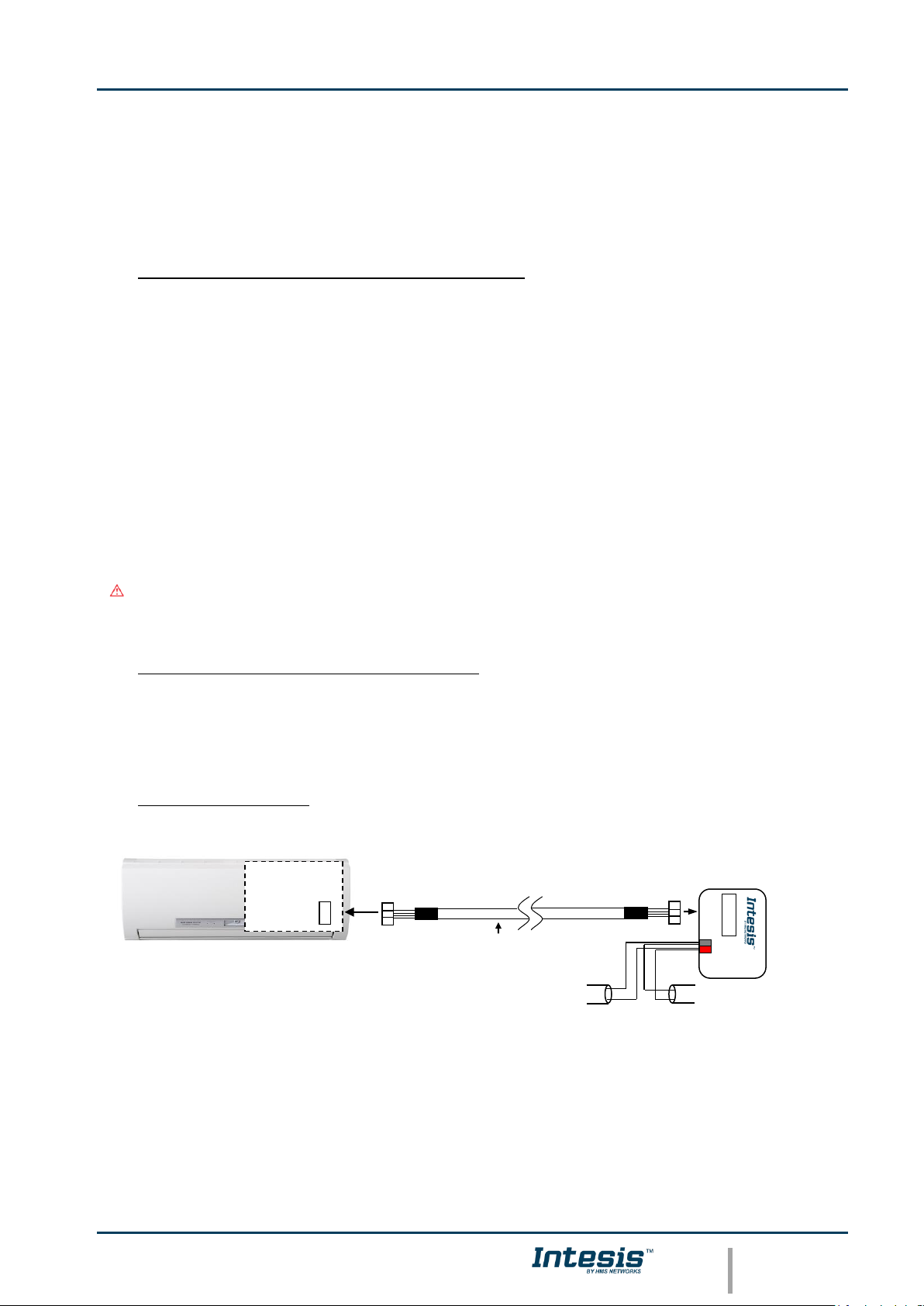
2. Connection
The interface comes with a cable (1,9 meters long) for direct connection to the internal
control board of the AC indoor unit.
o Connection of the interface to the AC indoor unit:
Disconnect mains power from the AC unit. Open the front cover of the indoor unit in order
to have access to the internal control board. In the control board locate the socket
connector marked as:
CN92 in Mr. Slim models.
or
CN105 in rest of models.
Using the cable that comes with the interface, insert one of its connectors, the one installed
in the shortest uncovered part, into the socket of the INKNXMIT001I000 marked as AC
Unit, and the other connector, the one in the largest uncovered part, into the socket CN92
or CN105 of the AC unit's control board. Fix the INKNXMIT001I000 inside or outside the AC
indoor unit depending on your needs, remember that INKNXMIT001I000 must be also
connected to the KNX bus. Close the AC indoor unit's front cover again.
Important: Do not modify the length of the cable supplied with the interface, it may
affect to the correct operation of the interface
o Connection of the interface to the KNX bus:
Disconnect power of the KNX bus. Connect the interface to the KNX TP-1 (EIB) bus using
the KNX standard connector (red/grey) of the interface, respect polarity. Reconnect power
of the KNX bus.
o Connections diagram:
Figure 2.2 Connection diagram
AC indoor unit
Connection cable
supplied with the
interface.
KNX TP-1
(EIB) bus
+
-
PROG
CN92
or
CN105
Internal
control board
AC Unit
KNX
- +
Phys. Addr.
Page 7

Intesis
TM
KNX – Mitsubishi Electric A.C.
User's manual r17.0 EN
© HMS Industrial Networks S.L.U. - All rights reserved
This information is subject to change without notice
URL https://www.intesis.com
7 / 32
3. Configuration and setup
This is a fully compatible KNX device which must be configured and setup using standard
KNX tool ETS.
ETS database for this device can be downloaded from:
https://intesis.com/products/ac-interfaces/mitsubishi-electric-gateways/mitsubishi-electric-domestic-mr.slimand-city-multi-to-knx-interface
Please consult the README.txt file, located inside the downloaded zip file, to find
instructions on how to install the database.
Important: Do not forget to select the correct settings of AC indoor unit being
connected to the INKNXMIT001I000. This is in "Parameters" of the device in ETS.
Page 8
Intesis
TM
KNX – Mitsubishi Electric A.C.
User's manual r17.0 EN
© HMS Industrial Networks S.L.U. - All rights reserved
This information is subject to change without notice
URL https://www.intesis.com
8 / 32
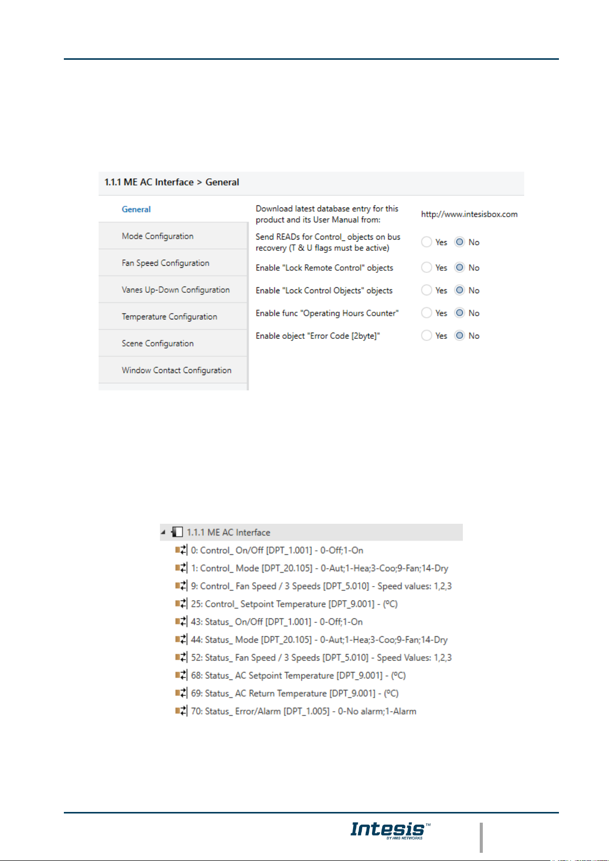
4. ETS Parameters
When imported to the ETS software for the first time, the gateway shows the following
default parameter configuration:
Figure 4.1 Default parameter configuration
With this configuration it’s possible to send On/Off (Control_ On/Off), change the AC Mode
(Control_ Mode), the Fan Speed (Control_ Fan Speed) and also the Setpoint Temperature
(Control_ Setpoint Temperature). The Status_ objects, for the mentioned Control_ objects,
are also available to use if needed. Also objects Status_ AC Return Temp and Status_
Error/Alarm are shown.
Figure 4.2 Default communication objects
Page 9
Intesis
TM
KNX – Mitsubishi Electric A.C.
User's manual r17.0 EN
© HMS Industrial Networks S.L.U. - All rights reserved
This information is subject to change without notice
URL https://www.intesis.com
9 / 32
4.1 General dialog
Inside this parameter’s dialog it is possible to activate or change the parameters shown in
the Figure 4.1.
The first field shows the URL where to download the database and the user manual for the
product.
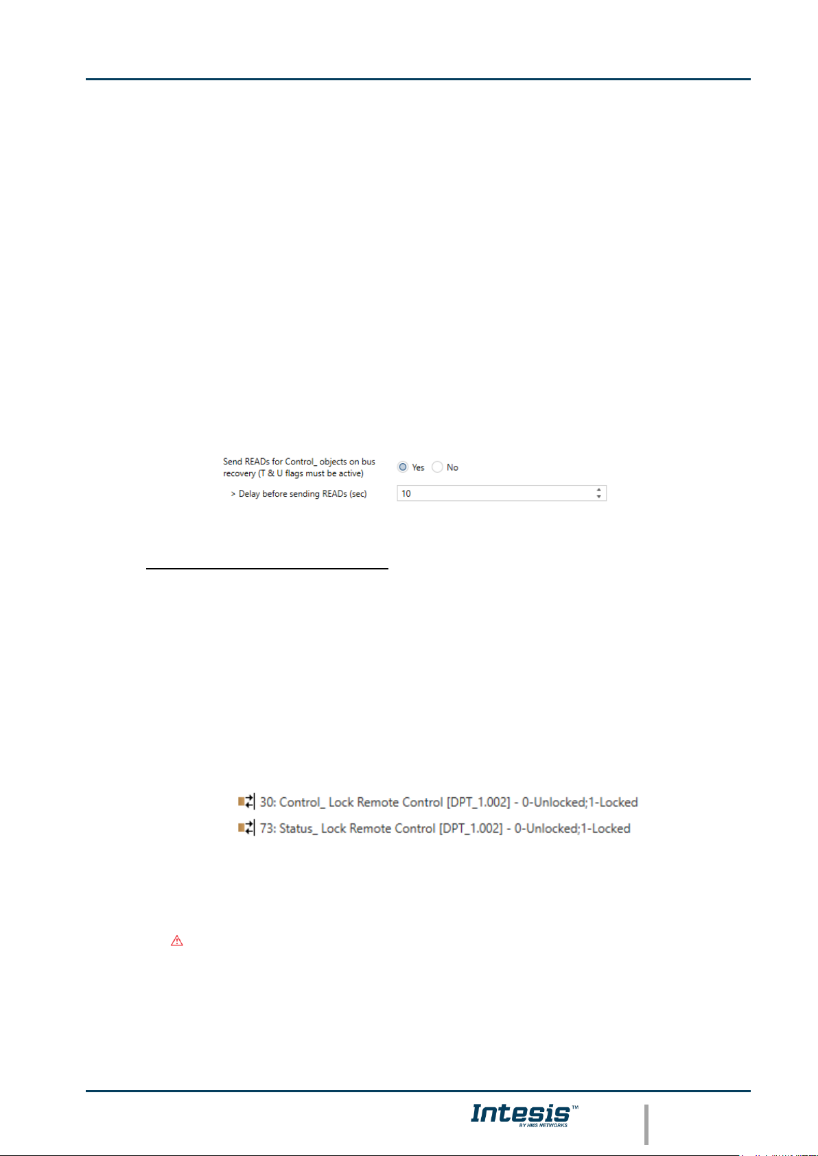
4.1.1 Send READs for Control_ objects on bus recovery
When this parameter is enabled, INKNXMIT001I000 will send READ telegrams for the group
addresses associated on its Control_ objects on bus recovery or application reset/start-up.
o If set to “no” the gateway will not perform any action.
o If set to “yes” all Control_ objects with both Transmit (T) and Update (U) flags
enabled will send READs and their values will be updated with the response when
received.
Figure 4.3 Parameter detail
➢ Delay before sending READs (sec):
With this parameter, a delay can be configured between 0 and 30 seconds for the
READs sent by the Control_ objects. This is to give time enough to other KNX
devices on the bus to start-up before sending the READs.
4.1.2 Enable comm obj “Ctrl_ Remote Lock”:
If set to “no” the object will not be shown.
If set to “yes” the Control_ Lock Remote Control object will appear.
• When a “1” value is sent to this communication object, the remote controller is
locked. To be unlocked a “0” value must be sent. The gateway remembers the
last value received even if a KNX bus reset/failure happens.
Important: If an initial scene is enabled and it has as Value for Remote Lock
(unchanged) or unlocked, this would unlock the remote controller because the
initial scene has priority over the Control_ Lock Remote Control
communication object.
Page 10
Intesis
TM
KNX – Mitsubishi Electric A.C.
User's manual r17.0 EN
© HMS Industrial Networks S.L.U. - All rights reserved
This information is subject to change without notice
URL https://www.intesis.com
10 / 32
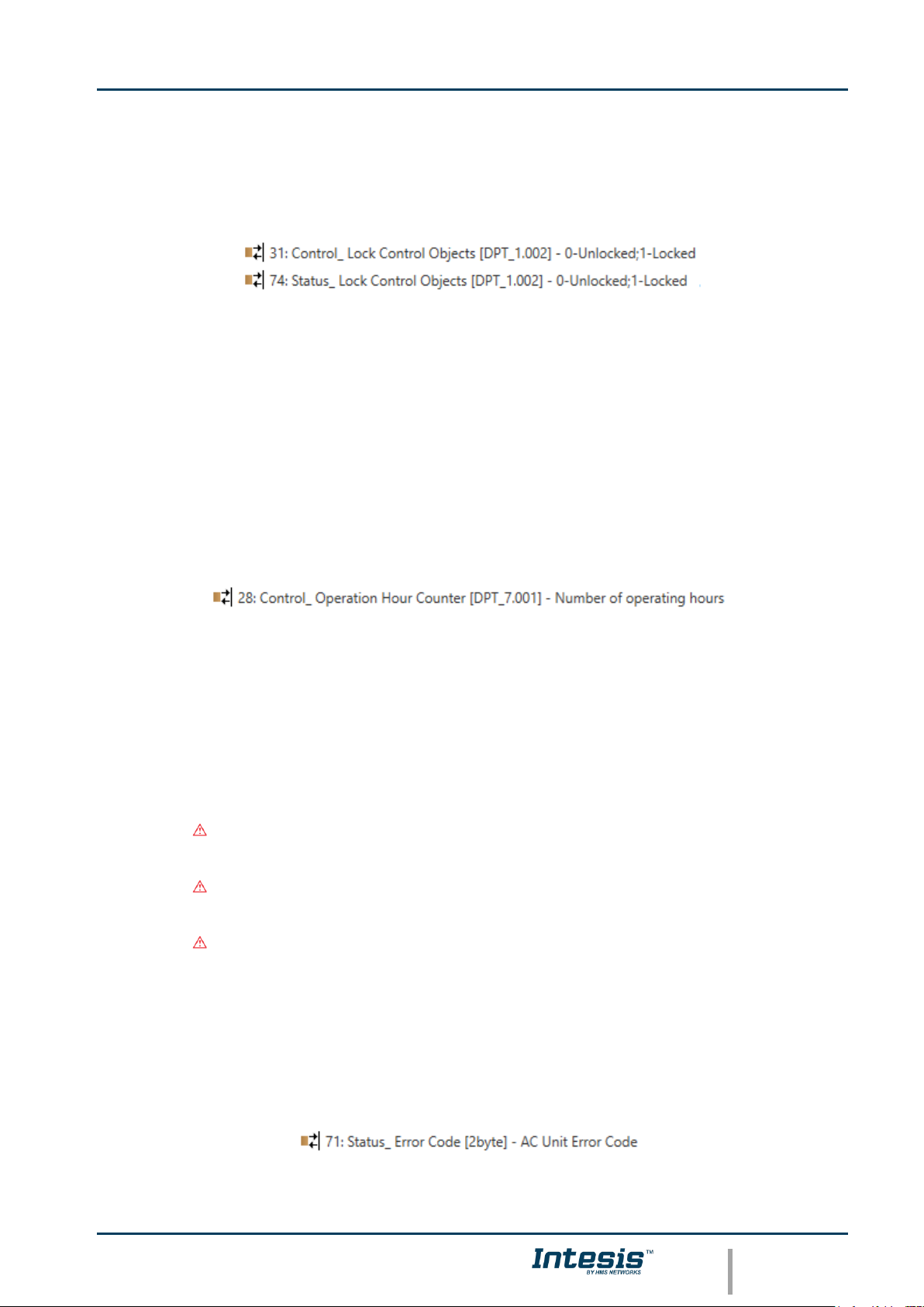
4.1.3 Enable func “Control_ Lock Control Obj”
This parameter shows/hide the Control_ Lock Control Obj communication object which,
depending on the sent value, locks or unlocks ALL the Control_ communication objects
except itself.
o If set to “no” the object will not be shown.
o If set to “yes” the Control_ Lock Control Objects object will appear.
• When a “1” value is sent to this communication object, all the Control_
objects will be locked. To unlock a “0” value must be sent, as the gateway
remembers the last value received even if a KNX bus reset/failure happens.
4.1.4 Enable func “Operating Hours Counter”
This parameter shows/hides the Status_ Operation Hour Counter communication object
which counts the number of operating hours for the INKNXMIT001I000.
o If set to “no” the object will not be shown.
o If set to “yes” the Status_ Operation Hour Counter object will appear.
• This object can be read and sends its status every time an hour is counted.
The gateway keeps that count in memory and the status is sent also after a
KNX bus reset/failure. Although this object is marked as a Status_ object it
also can be written to update the counter when needed. To reset the counter
should be written a “0” value.
Important: This object comes by default without the write (W) flag
activated. If is necessary to write on it, this flag must be activated.
Important: This object will also return its status, every time a value is
written, only if it’s different from the existing one.
Important: If the stored value is 0 hours, the gateway will not send the
status to KNX.
4.1.5 Enable object “Error Code [2byte]”
This parameter shows/hides the Status_ Error Code communication object which shows the
indoor unit errors, if occurred, in numeric format.
o If set to “no” the object will not be shown.
Page 11

Intesis
TM
KNX – Mitsubishi Electric A.C.
User's manual r17.0 EN
© HMS Industrial Networks S.L.U. - All rights reserved
This information is subject to change without notice
URL https://www.intesis.com
11 / 32
o If set to “yes” the Status_ Error Code [2byte] object will appear.
• This object can be read and also sends the indoor unit error, if occurred, in
numeric format. If a “0” value is shown that means no error.
4.2 Mode Configuration dialog
Figure 4.4 Default Mode Configuration dialog
All the parameters in this section are related with the different mode properties and
communication objects.
The byte-type communication object for Mode works with the DTP_20.105. Auto mode will
be enabled with a “0” value, Heat mode with a “1” value, Cool mode with a “3” value, Fan
mode with a “9” value and Dry mode with a “14” value.
4.2.1 Indoor unit has FAN mode
This parameter has to be used to indicate if the indoor unit has the fan mode available.
o If set to “no”, the indoor unit doesn’t have the fan mode available.
o If set to “yes”, the infoor unit has the fan mode available.
Important: Read the documentation of your indoor unit to check if it has FAN mode
available.
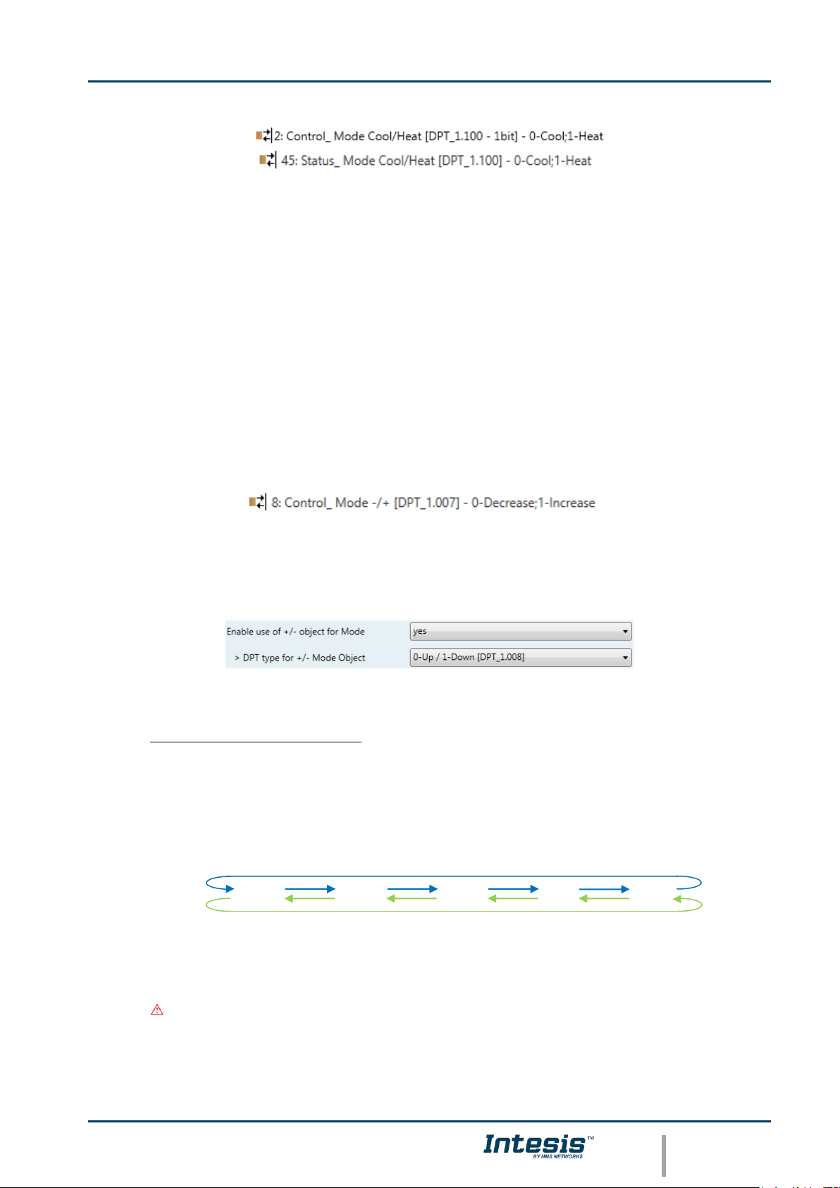
4.2.2 Enable use of Heat / Cool bit-type obj
This parameter shows/hides the Control_ and Status_ Mode Cool/Heat communication
objects.
Page 12
Intesis
TM
KNX – Mitsubishi Electric A.C.
User's manual r17.0 EN
© HMS Industrial Networks S.L.U. - All rights reserved
This information is subject to change without notice
URL https://www.intesis.com
12 / 32
o If set to “no” the objects will not be shown.
o If set to “yes” the Control_ and Status_ Mode Cool/Heat objects will appear.
• When a “1” value is sent to the Control_ communication object, Heat mode
will be enabled in the indoor unit, and the Status_ object will return this
value.
• When a “0” value is sent to the Control_ communication object, Cool mode
will be enabled in the indoor unit, and the Status_ object will return this
value.
4.2.3 Enable use of + / - object for Mode
This parameter shows/hides the Control_ Mode +/- communication object which lets change
the indoor unit mode by using two different datapoint types.
o If set to “no” the object will not be shown.
o If set to “yes” the Control_ Mode +/- object and a new parameter will appear.
Figure 4.5 Parameter detail
➢ DPT type for +/- Mode Object
This parameter lets choose between the datapoints 0-Up / 1-Down [DPT_1.008]
and 0-Decrease / 1-Increase [DPT_1.007] for the Control_ Mode +/- object.
The sequence followed when using this object is shown below:
Important: Read the documentation of your indoor unit to check if it has FAN
mode available.
▪ Up / Increase
▪ Down / Decrease
DRY
AUTO
HEAT
COOL
FAN
Page 13
Intesis
TM
KNX – Mitsubishi Electric A.C.
User's manual r17.0 EN
© HMS Industrial Networks S.L.U. - All rights reserved
This information is subject to change without notice
URL https://www.intesis.com
13 / 32
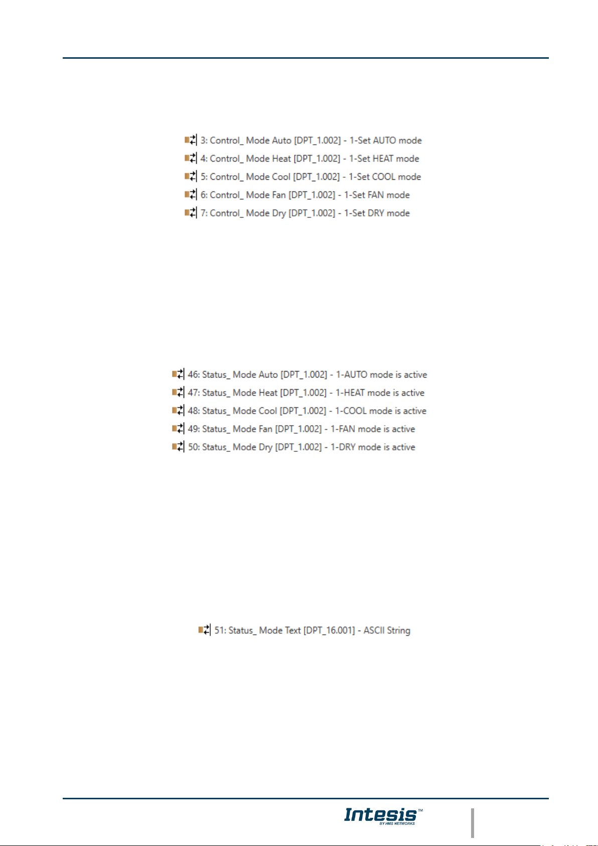
4.2.4 Enable use of bit-type Mode objects (for control)
This parameter shows/hides the bit-type Control_ Mode objects.
o If set to “no” the objects will not be shown.
o If set to “yes” the Control_ Mode objects for Auto, Heat, Cool, Fan and Dry will
appear. To activate a mode by using these objects a “1” value has to be sent.
4.2.5 Enable use of bit-type Mode objects (for status)
This parameter shows/hides the bit-type Status_ Mode objects.
o If set to “no” the objects will not be shown.
o If set to “yes” the Status_ Mode objects for Auto, Heat, Cool, Fan and Dry will
appear. When enabled, a mode will return a “1” through its bit-type object.
4.2.6 Enable use of Text object for Mode
This parameter shows/hides the Status_ Mode Text communication object.
o If set to “no” the object will not be shown.
o If set to “yes” the Status_ Mode Text object will appear. Also, in the parameters,
will be shown five text fields, one for each mode, that will let modify the text string
displayed by the Status_ Mode Text when changing mode.
Page 14

Intesis
TM
KNX – Mitsubishi Electric A.C.
User's manual r17.0 EN
© HMS Industrial Networks S.L.U. - All rights reserved
This information is subject to change without notice
URL https://www.intesis.com
14 / 32
Figure 4.6 Parameter detail
4.2.7 Enable use of Legacy_ object for Mode
This parameter shows/hides the Legacy_ Mode communication object
o If set to “no” the communication object will not be shown.
o If set to “yes” the Legacy_ Mode communication object will appear. This object lets
change the indoor unit mode but it uses a different data type. It is used to maintain
compatibility with old gateway models.
4.3 Fan Speed Configuration dialog
Figure 4.7 Default Fan Speed Configuration dialog
All the parameters in this section are related with the Fan Speed properties and
communication objects.
4.3.1 Fan is accessible in Indoor unit
This parameter lets choose if the unit has Fan Speed control available or not.
Page 15

Intesis
TM
KNX – Mitsubishi Electric A.C.
User's manual r17.0 EN
© HMS Industrial Networks S.L.U. - All rights reserved
This information is subject to change without notice
URL https://www.intesis.com
15 / 32
Figure 4.8 Parameter detail
o If set to “no” all the parameters and communication objects for the Fan Speed will
not be shown.
o If set to “yes” all the parameters and communication objects (if enabled in the
parameters dialog) for the Fan Speed will be shown.
Important: Read the documentation of your indoor unit to check if Fan Speed control is
available.
4.3.2 Available fanspeeds in Indoor Unit
This parameter lets choose how many fan speeds are available in the indoor unit.
Figure 4.9 Parameter detail
Important: Read the documentation of your indoor unit to check how many fan speeds
are available.
4.3.3 Indoor unit has AUTO fan speed
This parameter lets choose if the indoor unit has Auto Fan Speed available or not.
Figure 4.10 Parameter detail
o If set to “no” all the parameters and communication objects for the Auto Fan Speed
will not be shown.
o If set to “yes” a new parameter will appear. Find more information on section 2.4.6
Enable “Fan Speed Manual/Auto” objects.
Figure 4.11 Parameter detail
Important: Read the documentation of your indoor unit to check if Auto Fan Speed is
available.
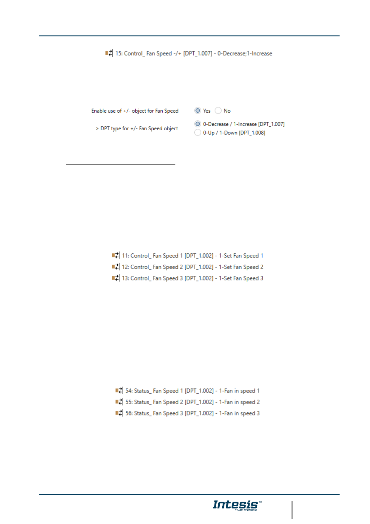
4.3.4 Enable use of +/- object for Fan Speed
This parameter shows/hides the Control_ Fan Speed +/- communication object which lets
increase/decrease the indoor unit fan speed by using two different datapoint types.
Page 16
Intesis
TM
KNX – Mitsubishi Electric A.C.
User's manual r17.0 EN
© HMS Industrial Networks S.L.U. - All rights reserved
This information is subject to change without notice
URL https://www.intesis.com
16 / 32
o If set to “no” the object will not be shown.
o If set to “yes” the Control_ Fan Speed +/- object and a new parameter will appear.
Figure 4.12 Parameter detail
➢ DPT type for +/- Fan Speed Object
This parameter lets choose between the datapoints 0-Up / 1-Down [DPT_1.008]
and 0-Decrease / 1-Increase [DPT_1.007] for the Control_ Fan Speed +/-
object.
4.3.5 Enable use of bit-type Fan Speed objects (for Control)
This parameter shows/hides the bit-type Control_ Fan Speed objects.
o If set to “no” the objects will not be shown.
o If set to “yes” the Control_ Fan Speed objects for Speed 1, Speed 2, Speed 3 (if
available), and Speed 4 (if available) will appear. To activate a Fan Speed by using
these objects a “1” value has to be sent.
4.3.6 Enable use of bit-type Fan Speed objects (for Status)
This parameter shows/hides the bit-type Status_ Fan Speed objects.
o If set to “no” the objects will not be shown.
o If set to “yes” the Status_ Fan Speed objects for Speed 1, Speed 2, Speed 3 (if
available), and Speed 4 (if available) will appear. When a Fan Speed is enabled, a
“1” value is returned through its bit-type object.
Page 17
Intesis
TM
KNX – Mitsubishi Electric A.C.
User's manual r17.0 EN
© HMS Industrial Networks S.L.U. - All rights reserved
This information is subject to change without notice
URL https://www.intesis.com
17 / 32
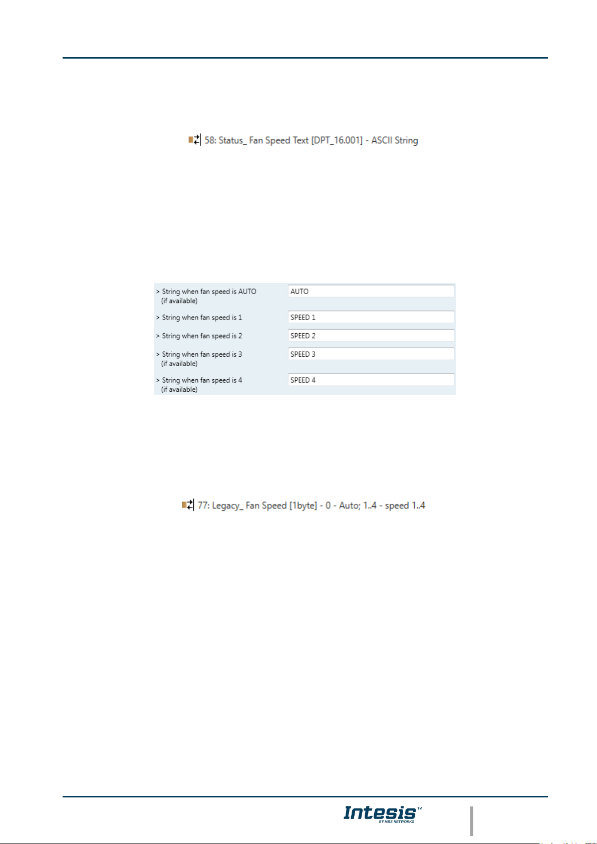
4.3.7 Enable use of Text object for Fan Speed
This parameter shows/hides the Status_ Fan Speed Text communication object.
o If set to “no” the object will not be shown.
o If set to “yes” the Status_ Fan Speed Text object will appear. Also, in the
parameters, will be shown five text fields, one for each Fan Speed, that will let
modify the text string displayed by the Status_ Fan Speed Text when changing a fan
speed.
Figure 4.13 Parameter detail
4.3.8 Enable use of Legacy_ object for Fan Speed
This parameter shows/hides the Legacy_ Fan Speed communication object
o If set to “no” the communication object will not be shown.
o If set to “yes” the communication object will appear. This object lets change the
indoor unit fan speed but it uses a different data type. It is used to maintain
compatibility with old gateway models.
4.4 Vanes Up-Down Configuration dialog
Page 18

Intesis
TM
KNX – Mitsubishi Electric A.C.
User's manual r17.0 EN
© HMS Industrial Networks S.L.U. - All rights reserved
This information is subject to change without notice
URL https://www.intesis.com
18 / 32
Figure 4.14 Vanes Up-Down Configuration dialog
All the parameters in this section are related with the Vanes Up-Down properties and
communication objects.
4.4.1 Indoor unit has U-D Vanes
This parameter lets choose if the unit has Up-Down Vanes available or not.
Figure 4.15 Parameter detail
o If set to “no” all the parameters and communication objects for the Up-Down Vanes
will not be shown.
o If set to “yes” all the parameters and communication objects (if enabled in the
parameters dialog) for the Up-Down Vanes will be shown.
Important: Read the documentation of your indoor unit to check if Up-Down Vanes are
available.
4.4.2 Available positions in Indoor Unit
This parameter lets choose how many vane positions are available in the indoor unit.
Figure 4.16 Parameter detail
Important: Read the documentation of your indoor unit to check how many vane
positions are available.
4.4.3 Indoor unit has AUTO Vanes U-D
This parameter lets choose if the indoor unit has Auto Vanes U-D available or not.
Page 19

Intesis
TM
KNX – Mitsubishi Electric A.C.
User's manual r17.0 EN
© HMS Industrial Networks S.L.U. - All rights reserved
This information is subject to change without notice
URL https://www.intesis.com
19 / 32
Figure 4.17 Parameter detail
o If set to “no” all the parameters and communication objects for the Auto Vanes U-D
will not be shown.
o If set to “yes” a new parameter will appear. Find more information on section
Enable “Vanes U-D Man/Auto” objects (for Control and Status).
Figure 4.18 Parameter detail
Important: Read the documentation of your indoor unit to check if Auto Vane Position
is available.
4.4.4 Enable “Vanes U-D Swing” objects (for Control and Status)
This parameter shows/hides the Control_ Vanes U-D Swing and Status_ Vanes U-D Swing
communication objects.
o If set to “no” the objects will not be shown.
o If set to “yes” the Control_ Vanes U-D Swing and Status_ Vanes U-D Swing objects
will appear.
• When a “1” value is sent to the Control_ communication object, Vanes Up-
Down will be in Auto mode, and the Status_ object will return this value.
• When a “0” value is sent to the Control_ communication object, Vanes Up-
Down will be in Manual mode and the first position will be enabled. The
Status_ object will return this value.
4.4.5 Enable use of +/- object for Vanes U-D
This parameter shows/hides the Control_ Vane Up-Down +/- communication object which
lets change the indoor unit vane position by using two different datapoint types.
o If set to “no” the object will not be shown.
Page 20

Intesis
TM
KNX – Mitsubishi Electric A.C.
User's manual r17.0 EN
© HMS Industrial Networks S.L.U. - All rights reserved
This information is subject to change without notice
URL https://www.intesis.com
20 / 32
o If set to “yes” the Control_ Vanes U-D +/- object and a new parameter will appear.
Figure 4.19 Parameter detail
➢ DPT type for +/- Vane Up-Down obj
This parameter lets choose between the datapoints 0-Up / 1-Down [DPT_1.008]
and 0-Decrease / 1-Increase [DPT_1.007] for the Control_ Vanes U-D +/-
object.
4.4.6 Enable use of bit-type Vane U-D objects (for Control)
This parameter shows/hides the bit-type Control_ Vanes U-D objects.
o If set to “no” the objects will not be shown.
o If set to “yes” the Control_ Vanes U-D objects for each Position will appear. To
activate a Vanes Position by using these objects, a “1” value has to be sent.
4.4.7 Enable use of bit-type Vane U-D objects (for Status)
This parameter shows/hides the bit-type Status_ Vanes U-D objects.
o If set to “no” the objects will not be shown.
o If set to “yes” the Status_ Vanes U-D objects for each Position will appear. When a
Vanes Position is enabled, a “1” value is returned through its bit-type object.
4.4.8 Enable “Vanes U-D Man/Auto” objects (for Control and Status)
Page 21

Intesis
TM
KNX – Mitsubishi Electric A.C.
User's manual r17.0 EN
© HMS Industrial Networks S.L.U. - All rights reserved
This information is subject to change without notice
URL https://www.intesis.com
21 / 32
This parameter shows/hides the Control_ Vanes U-D Man/Auto and Status_ Vanes U-D
Man/Auto communication objects.
o If set to “no” the objects will not be shown.
o If set to “yes” the Control_ Vanes U-D Man/Auto and Status_ Vanes U-D Man/Auto
objects will appear.
• When a “1” value is sent to the Control_ communication object, Vanes Up-
Down will be in Auto mode, and the Status_ object will return this value.
• When a “0” value is sent to the Control_ communication object, Vanes Up-
Down will be in Manual mode and the first position will be enabled. The
Status_ object will return this value.
Important: When in Auto Mode the indoor unit will choose the most
appropriate vane up-down position, but this will be shown neither in KNX nor
in the remote controller.
4.4.9 Enable use of Text object for Vane U-D
This parameter shows/hides the Status_ Vanes U-D Text communication object.
o If set to “no” the object will not be shown.
o If set to “yes” the Status_ Vanes U-D Text object will appear. Also, in the
parameters will be shown seven text fields, five for the Vane Position and one for the
Auto function and another one for the Swing function, that will let modify the text
string displayed by the Status_ Vanes U-D Text when changing a vane position.
Figure 4.20 Parameter detail
4.4.10 Enable use of Legacy_ object for Vanes
This parameter shows/hides the Legacy_ Vanes communication object
Page 22

Intesis
TM
KNX – Mitsubishi Electric A.C.
User's manual r17.0 EN
© HMS Industrial Networks S.L.U. - All rights reserved
This information is subject to change without notice
URL https://www.intesis.com
22 / 32
o If set to “no” the communication object will not be shown.
o If set to “yes” the communication object will appear. This object lets change the
indoor unit vanes behavior but it uses a different data type. It is used to maintain
compatibility with old gateway models.
4.5 Temperature Configuration dialog
Figure 4.21 Default Temperature Configuration dialog
All the parameters in this section are related with the Temperature properties and
communication objects.
4.5.1 Enable use of +/- object for Setpoint Temp
This parameter shows/hides the Control_ Setpoint Temp +/- communication object which
lets change the indoor unit setpoint temperature by using two different datapoint types.
o If set to “no” the object will not be shown.
o If set to “yes” the Control_ Setpoint Temp +/- object and a new parameter will
appear.
Figure 4.22 Parameter detail
Page 23

Intesis
TM
KNX – Mitsubishi Electric A.C.
User's manual r17.0 EN
© HMS Industrial Networks S.L.U. - All rights reserved
This information is subject to change without notice
URL https://www.intesis.com
23 / 32
➢ DPT type for +/- Setp Temp object
This parameter lets choose between the datapoints 0-Up / 1-Down [DPT_1.008]
and 0-Decrease / 1-Increase [DPT_1.007] for the Control_ Setpoint Temp +/-
object.
4.5.2 Ambient temp. ref. is provided from KNX
This parameter shows/hides the Control_ Ambient Temperature communication object
which lets use an ambient temperature reference provided by a KNX device.
o If set to “no” the object will not be shown.
o If set to “yes” the Control_ Ambient Temperature object will appear. Meant to be
enabled when you want the temperature provided by a KNX sensor to be the
reference ambient temperature for the air conditioner. Then, the following formula
applies for calculation of real Control_ Setpoint Temperature sent to the AC unit:
As an example, consider the following situation:
User wants: 19ºC (“KNX Setp. Temp.”)
User sensor (a KNX sensor) reads: 21ºC (“KNX Amb Temp.”)
Ambient temp. read by Mitsubishi system is: 24ºC (“AC Ret. Temp”)
In this example, the final setpoint temperature that ME-AC-KNX-1 will send out to the
indoor unit (shown in “Setp. Temp.”) will become 24ºC – (21ºC - 19ºC) = 22ºC. This is
the setpoint that will actually be requested to Mitsubishi Electric unit.
This formula will be applied as soon as the Control_ Setpoint Temperature and Control_
Ambient Temperature objects are written at least once from the KNX installation. After
that, they are kept always consistent.
Note that this formula will always drive the AC indoor unit demand in the right direction,
regardless of the operation mode (Heat, Cool or Auto).
4.6 Scene Configuration dialog
▪ Up / Increase
▪ Down / Decrease
…
19ºC
20ºC
28ºC
27ºC
(Upper limit)
(Lower limit)
“AC Setp. Temp” = “AC Ret. Temp” - (“KNX Amb. Temp.” - “KNX Setp. Temp”)
▪ AC Setp. Temp: AC indoor unit setpoint temperature
▪ AC Ret. Temp: AC indoor unit return temperature
▪ KNX Amb. Temp.: Ambient temperature provided from KNX
▪ KNX Setp. Temp: Setpoint temperature provided from KNX
Page 24

Intesis
TM
KNX – Mitsubishi Electric A.C.
User's manual r17.0 EN
© HMS Industrial Networks S.L.U. - All rights reserved
This information is subject to change without notice
URL https://www.intesis.com
24 / 32
Figure 4.23 Parameter detail
All the parameters in this section are related with the Scene properties and communication
objects. A scene contains values of: On/Off, Mode, Fan speed, Vane position, Setpoint
Temperature and Remote Controller Disablement.
4.6.1 Enable use of scenes
This parameter shows/hides the scene configuration parameters and communication
objects.
o If set to “no” the scene parameters and communication objects will not be shown.
o If set to “yes” the scene parameters and communication objects will be shown. To
execute a scene through the byte-type object, a value from “0” to “4” has to be
sent, correponding each one to a different scene (i.e. “0” = Scene 1;… “4” = Scene
5).
4.6.2 Enable use of bit objects for scene execution
This parameter shows/hides the Control_ Execute Scene bit-type communication objects.
Page 25

Intesis
TM
KNX – Mitsubishi Electric A.C.
User's manual r17.0 EN
© HMS Industrial Networks S.L.U. - All rights reserved
This information is subject to change without notice
URL https://www.intesis.com
25 / 32
o If set to “no” the communication objects will not be shown.
o If set to “yes” the communication objects will appear. To execute a scene by using
these objects, a “1” value has to be sent to the scene’s object we want to execute
(i.e. to execute scene 4, a “1” has to be sent to the Control_ Execute Scene 4
object).
4.6.3 Enable use of bit objects for storing scenes
This parameter shows/hides the Control_ Store Scene bit-type communication objects.
o If set to “no” the objects will not be shown.
o If set to “yes” the Control_ Store Scene objects for storing scenes will appear. To store
a scene by using these objects, a “1” value has to be sent to the scene’s object we want
to store (i.e. to store scene 4, a “1” has to be sent to the Control_ Store Scene 4
object).
4.7 Enable use of Window Contact function
This parameter shows/hides the Control_ Switch Off Timeout communication object which
lets Start/Stop a timeout to switch off the indoor unit.
o If set to “no” the object will not be shown.
o If set to “yes” the Control_ Switch Off Timeout object and new parameters will
appear. If a “1” value is sent to this object, and the indoor unit is already turned on,
the switch-off timeout will begin. If a “0” value is sent to this object, the switch-off
timeout will stop.
Page 26

Intesis
TM
KNX – Mitsubishi Electric A.C.
User's manual r17.0 EN
© HMS Industrial Networks S.L.U. - All rights reserved
This information is subject to change without notice
URL https://www.intesis.com
26 / 32
Figure 4.24 Parameter detail
➢ AC switch-off timeout (min)
This parameter lets select how much time (in minutes) to wait before switching off
the indoor unit.
➢ Reload last On/Off val once window is closed?
If set to “no”, once the switch-off timeout is stopped, any value will be reloaded.
If set to “yes”, once the switch-off timeout is stopped, the last On/Off value sent
will be reloaded.
• If a “1” value is sent to the Control_ Switch Off Timeout object after the
timeout period, the indoor unit will turn on.
• If a “0” value is sent to the Control_ Switch Off Timeout after the timeout
period, no action will be performed.
Page 27

Intesis
TM
KNX – Mitsubishi Electric A.C.
User's manual r17.0 EN
© HMS Industrial Networks S.L.U. - All rights reserved
This information is subject to change without notice
URL https://www.intesis.com
27 / 32
5. Specifications
Enclosure
ABS (UL 94 HB) de 2,5 mm thick
Net dimensions (dxwxh):
59 x 36 x 21 mm / 4” x 2.8” x 1.2”
Color: Light White
Operation
Temperature
-25ºC to 60ºC
Weight
42 g.
Stock
Temperature
-40ºC to 85ºC
Power supply
29V DC, 5mA
Supplied through KNX bus.
Operational
Humidity
<90% RH, non-condensing
Terminal Wiring
(for low-voltage
signals)
For terminal: solid wires or stranded wires
(twisted or with ferrule)
1 core: 0.5mm2… 2.5mm2
2 cores: 0.5mm2… 1.5mm2
3 cores: not permitted
Stock Humidity
<90% RH, non-condensing
KNX port
1 x KNX TP1 (EIB) port opto-isolated.
Plug-in terminal block (2 poles). TNV-1
Isolation voltage
4000 V
AC unit port
1 x Specific connector
Specific cable included
Protection
IP20 (IEC60529)
Configuration
Configuration with ETS
Buttons
1 x KNX programming
LED indicators
1 x KNX programming
RoHS
conformity
Compliant with RoHS directive
(2002/95/CE).
Certifications
Certifications
CE conformity to EMC directive (2004/108/EC) and Low-voltage
directive (2006/95/EC)
EN 61000-6-3; 61000-6-1; EN 60950-1; EN 50491-3;
Programming LED
AC Indoor Unit
Connection
59 mm
36 mm
21 mm
Programming button
KNX bus
Connection
Page 28

Intesis
TM
KNX – Mitsubishi Electric A.C.
User's manual r17.0 EN
© HMS Industrial Networks S.L.U. - All rights reserved
This information is subject to change without notice
URL https://www.intesis.com
28 / 32
6. AC Unit Types compatibility.
A list of Mitsubishi Electric indoor unit models compatible with INKNXMIT001I000 and their
available features can be found in:
https://www.intesis.com/docs/compatibilities/inxxxmit001ix00_compatibility
Page 29

Intesis
TM
KNX – Mitsubishi Electric A.C.
User's manual r17.0 EN
© HMS Industrial Networks S.L.U. - All rights reserved
This information is subject to change without notice
URL https://www.intesis.com
29 / 32
7. Error Codes
Error Code
Description
-1
Communication error between the INKNXMIT001I000 gateway and the AC unit
0
No active error
0001
Communication error with the AC unit
1102
Discharge Temperature high
1108
Internal thermostat detector working (49C)
1110
Outdoor unit fail
1300
Pressure low
1302
Pressure high (High pressure probe working 63H)
1503
Protection against freeze or battery high temperature
1504
Protection against freeze or battery high temperature
1504
Overheating protection
1509
High pressure error (ball valve closed)
1520
Super heating anomaly due to low temp. of discharge. (TH4)
2500
Erroneous operation of drain pump
2502
Erroneous operation of drain pump
2503
Drain sensor anomaly (DS)
4030
Serial transmission error
4100
Compressor pause due to excess of current (initial block)
4101
Compressor pause due to excess of current (overload)
4102
Phase detection opened
4103
Anti-phase detection
4108
Phase opened in phase L2 or connector 51CM opened
4118
Error in the anti-phase detector (electronic board)
4124
Connector 49L opened
4210
Cut due to over-current of compressor
4220
Voltage anomaly
4230
Radiator panel temperature anomaly (TH8)
5101
Ambient temperature probe anomaly (TH1), indoor unit
5102
Liquid probe anomaly (TH2)
5103
Cond/Evap probe anomaly (TH5)
5104
Error detection in discharge temperature
5105
Outdoor probe error TH3
5106
Outdoor probe errorTH7
5107
Outdoor probe errorTH6
5110
Outdoor probe errorTH8
5202
Connector 63L opened
5300
Current probe error
6600
MNET duplicated address definition
6602
MNET Line transmission hardware error
6603
MNET BUS busy
6606
MNET Line transmission error
6607
MNET transmission error
6607
MNET without ack
6608
MNET transmission error
6608
MNET without response
6831
IR remote control transmission error (reception error)
6832
IR remote control transmission error (transmission error)
6840
Transmission error with the indoor/outdoor unit (reception error)
6841
Transmission error with the indoor/outdoor unit (transmission error)
6844
Error in inter-connection cable in the indoor/outdoor unit, indoor unit number deactivated (5 min or
more)
6845
Error in inter-connection cable in the indoor/outdoor unit (cabling error, disconnection)
6846
Initial timer deactivated
In case you detect an error code not listed, contact your nearest Mitsubishi Electric technical
support service for more information on the error meaning.
Page 30

Intesis
TM
KNX - Mitsubishi Electric A.C.
User's manual r17.0 EN
© HMS Industrial Networks S.L.U. - All rights reserved
This information is subject to change without notice
URL https://www.intesis.com
30 / 32
Appendix A – Communication Objects Table
TOPIC
OBJECT
NUMBER
NAME
LENGTH
DATAPOINT TYPE
FLAGS
FUNCTION
DPT_NAME
DPT_ID
R W T
U
On/Off
0
Control_ On/Off
1 bit
DPT_Switch
1.001
W T 0 - Off; 1-On
Mode
1
Control_ Mode
1 byte
DPT_HVACContrMode
20.105
W T 0 - Auto; 1 - Heat; 3 - Cool; 9 - Fan; 14 - Dry
2
Control_ Mode Cool/Heat
1 bit
DPT_Heat/Cool
1.100
W T 0 - Cool; 1 - Heat;
3
Control_ Mode Auto
1 bit
DPT_Bool
1.002
W T 1 - Auto
4
Control_ Mode Heat
1 bit
DPT_Bool
1.002
W T 1 - Heat
5
Control_ Mode Cool
1 bit
DPT_Bool
1.002
W T 1 - Cool
6
Control_ Mode Fan
1 bit
DPT_Bool
1.002
W T 1 - Fan
7
Control_ Mode Dry
1 bit
DPT_Bool
1.002
W T 1 - Dry
8
Control_ Mode -/+ /
Control_ Mode +/-
1 bit
DPT_Step /
DPT_UpDown
1.007 /
1.008
W
0 - Decrease; 1 – Increase /
0 - Up; 1 - Down
Fan Speed
9
Control_ Fan Speed / 2 (3)(4) Speeds
1 byte
DPT_Enumerated
5.010
W T 1 - Speed 1; 2 - Speed 2; (3 Speed 3; 4 - Speed 4)
10
Control_ Fan Speed Manual/Auto
1 bit
DPT_Bool
1.002
W T 0 - Manual; 1 - Auto
11
Control_ Fan Speed 1
1 bit
DPT_Bool
1.002
W T 1 – Set Fan Speed 1
12
Control_ Fan Speed 2
1 bit
DPT_Bool
1.002
W T 1 – Set Fan Speed 2
13
Control_ Fan Speed 3
1 bit
DPT_Bool
1.002
W T 1 – Set Fan Speed 3
14
Control_ Fan Speed 4
1 bit
DPT_Bool
1.002
W T 1 – Set Fan Speed 4
15
Control_ Fan Speed -/+ /
Control_ Fan Speed +/-
1 bit
DPT_Step /
DPT_UpDown
1.007 /
1.008
W
0 - Decrease; 1 – Increase /
0 - Up; 1 - Down
anes
Up-Down
16
Control_ Vanes U-D / 5 pos
1 byte
DPT_Enumerated
5.010
W T 1 - Pos1; 2 - Pos2; 3 - Pos3; 4 - Pos4; 5 - Pos5
17
Control_ Vanes U-D Man/Auto
1 bit
DPT_Bool
1.002
W T 0 – Manual; 1 - Auto
18
Control_ Vanes U-D Pos1
1 bit
DPT_Bool
1.002
W T 1 – Set Position 1
19
Control_ Vanes U-D Pos2
1 bit
DPT_Bool
1.002
W T 1 – Set Position 2
20
Control_ Vanes U-D Pos3
1 bit
DPT_Bool
1.002
W T 1 – Set Position 3
21
Control_ Vanes U-D Pos4
1 bit
DPT_Bool
1.002
W T 1 – Set Position 4
22
Control_ Vanes U-D Pos5
1 bit
DPT_Bool
1.002
W T 1 – Set Position 5
23
Control_ Vanes U-D Swing
1 bit
DPT_Bool
1.002
W T 0 – Off; 1 – Swing
Page 31

Intesis
TM
KNX - Mitsubishi Electric A.C.
User's manual r17.0 EN
© HMS Industrial Networks S.L.U. - All rights reserved
This information is subject to change without notice
URL https://www.intesis.com
31 / 32
24
Control_ Vanes U-D -/+ /
Control_ Vanes U-D +/-
1 bit
DPT_Step /
DPT_UpDown
1.007 /
1.008
W T
0 - Decrease; 1 – Increase /
0 - Up; 1 - Down
Temperature
25
Control_ Setpoint Temperature
2 byte
DPT_Value_Temp
9.001
W T (ºC)
26
Control_ Setpoint Temp -/+ /
Control_ Setpoint Temp +/-
1 bit
DPT_Step /
DPT_UpDown
1.007 /
1.008
W
0 - Decrease; 1 – Increase /
0 - Up; 1 - Down
27
Control_ Ambient Temperature
2 byte
DPT_Value_Temp
9.001
W T (ºC)
Counter
28
Control_ Operation Hour Counter
2 byte
DPT_Value_2_Ucount
7.001
W T Number of operating hours
Window
29
Control_ Window Contact Status
1 bit
DPT_OpenClose
1.009
W T 0 - Open; 1 - Closed
Locking
30
Control_ Lock Remote Control
1 bit
DPT_Bool
1.002
W T 0 - Unlocked; 1 - Locked
31
Control_ Lock Control Objects
1 bit
DPT_Bool
1.002
W T 0 - Unlocked; 1 - Locked
Scenes
32
Control_ Store/Exec Scene
1 byte
DPT_SceneControl
18.001
W T 0..4-Exec1-5;128..132-Save1-5
33
Control_ Store Scene1
1 bit
DPT_Bool
1.002
W 1 - Store Scene
34
Control_ Store Scene2
1 bit
DPT_Bool
1.002
W 1 - Store Scene
35
Control_ Store Scene3
1 bit
DPT_Bool
1.002
W 1 - Store Scene
36
Control_ Store Scene4
1 bit
DPT_Bool
1.002
W 1 - Store Scene
37
Control_ Store Scene5
1 bit
DPT_Bool
1.002
W 1 - Store Scene
38
Control_ Execute Scene1
1 bit
DPT_Bool
1.002
W T 1 - Execute Scene
39
Control_ Execute Scene2
1 bit
DPT_Bool
1.002
W T 1 - Execute Scene
40
Control_ Execute Scene3
1 bit
DPT_Bool
1.002
W T 1 - Execute Scene
41
Control_ Execute Scene4
1 bit
DPT_Bool
1.002
W T 1 - Execute Scene
42
Control_ Execute Scene5
1 bit
DPT_Bool
1.002
W T 1 - Execute Scene
ON/OFF
43
Status_ On/Off
1 bit
DPT_Switch
1.001
R T 0 - Off; 1-On
Mode
44
Status_ Mode
1 byte
DPT_HVACContrMode
20.105
R T 0 - Auto; 1 - Heat; 3 - Cool; 9 - Fan; 14 - Dry
45
Status_ Mode Cool/Heat
1 bit
DPT_Heat/Cool
1.100
R T 0 - Cool; 1 - Heat
46
Status_ Mode Auto
1 bit
DPT_Bool
1.002
R T 1 - Auto
47
Status_ Mode Heat
1 bit
DPT_Bool
1.002
R T 1 - Heat
48
Status_ Mode Cool
1 bit
DPT_Bool
1.002
R T 1 - Cool
49
Status_ Mode Fan
1 bit
DPT_Bool
1.002
R T 1 - Fan
50
Status_ Mode Dry
1 bit
DPT_Bool
1.002
R T 1 - Dry
51
Status_ Mode Text
14 byte
DPT_String_8859_1
16.001
R T ASCII String
Fan
52
Status_ Fan Speed / 2 (3)(4) Speeds
1 byte
DPT_Enumerated
5.010
W T 1 - Speed 1; 2 - Speed 2; (3 Speed 3; 4 - Speed 4)
Page 32

Intesis
TM
KNX - Mitsubishi Electric A.C.
User's manual r17.0 EN
© HMS Industrial Networks S.L.U. - All rights reserved
This information is subject to change without notice
URL https://www.intesis.com
32 / 32
53
Status_ Fan Speed Manual/Auto
1 bit
DPT_Bool
1.002
R T 0 – Manual; 1 - Auto
54
Status_ Fan Speed 1
1 bit
DPT_Bool
1.002
R T 1 – Fan is in speed 1
55
Status_ Fan Speed 2
1 bit
DPT_Bool
1.002
R T 1 – Fan is in speed 2
56
Status_ Fan Speed 3
1 bit
DPT_Bool
1.002
R T 1 - Fan is in speed 3
57
Status_ Fan Speed 4
1 bit
DPT_Bool
1.002
R T 1 - Fan is in speed 4
58
Status_ Fan Speed Text
14 byte
DPT_String_8859_1
16.001
R T ASCII String
Vanes
Up-Down
59
Status_ Vanes U-D / 4 (5) pos
1 byte
DPT_Enumerated
5.010
R T 1 - Pos1; 2 - Pos2; 3 - Pos3; 4 - Pos4; (5 - Pos5)
60
Status_ Vanes U-D Man/Auto
1 bit
DPT_Bool
1.002
R T 0 – Manual; 1 - Auto
61
Status_ Vanes U-D Pos1
1 bit
DPT_Bool
1.002
R T 1 - Position 1
62
Status_ Vanes U-D Pos2
1 bit
DPT_Bool
1.002
R T 1 - Position 2
63
Status_ Vanes U-D Pos3
1 bit
DPT_Bool
1.002
R T 1 - Position 3
64
Status_ Vanes U-D Pos4
1 bit
DPT_Bool
1.002
R T 1 - Position 4
65
Status_ Vanes U-D Pos5
1 bit
DPT_Bool
1.002
R T 1 - Position 5
66
Status_ Vanes U-D Swing
1 bit
DPT_Bool
1.002
R
T
0 – Off; 1 – Swing
67
Status_ Vanes U-D Text
14 byte
DPT_String_8859_1
16.001
R T ASCII String
Temperature
68
Status_ AC Setpoint Temp
2 byte
DPT_Value_Temp
9.001
R T (ºC)
69
Status_ AC Return Temperature
2 byte
DPT_Value_Temp
9.001
R T (ºC)
Error
70
Status_ Error/Alarm
1 bit
DTP_Alarm
1.005
R T 0 - No Alarm; 1 - Alarm
71
Status_ Error Code
2 byte
Enumerated
R T
0 - No Error; Any other see user's manual
Counter
72
Status_ Operation Hour Counter
2 byte
DPT_Value_2_Ucount
7.001
R T Number of operating hours
Locking
73
Status_ Lock Remote Control
1 bit
DPT_Bool
1.002
R T 0 - Unlocked; 1 - Locked
74
Status_ Lock Control Objects
1 bit
DPT_Bool
1.002
R T 0 - Unlocked; 1 - Locked
Scene
75
Status_ Current Scene
1 byte
DPT_SceneNumber
17.001
R T 0 to 4 - Scene 1 to 5; 63 - No Scene
Legacy
76
Legacy_ Mode
1 byte
Enumerated
R T
0 - Auto; 1 - Heat; 2 - Dry; 3 - Fan; 4 - Cool
77
Legacy_ Fan Speed
1 byte
Enumerated
R T
0 – Auto; 1..4 – Speed 1..4
78
Legacy_ Vanes
1 byte
Enumerated
R T
0 – Auto; 1..5 – Pos 1..5; 6 - Swing
 Loading...