

Page 1

Compatible with VRF and Commercial lines
USER MANUAL
Issue date: 03/2021 r1.4 ENGLISH
Page 2

Intesis® INMBSMID---I000
User’s Manual r1.4 EN
© HMS Industrial Networks S.L.U - All rights reserved
This information is subject to change without notice
URL https://www.intesis.com
2 / 24
Modbus RTU (EIA-485) Interface for Midea
air conditioners
Compatible with VRF and Commercial lines
ORDER CODE
LEGACY ORDER CODE
INMBSMID001I000
MD-AC-MBS-1
INMBSMID004I000
MD-AC-MBS-4
INMBSMID008I000
MD-AC-MBS-8
INMBSMID032I000
MD-AC-MBS-32
Page 3

Intesis® INMBSMID---I000
User’s Manual r1.4 EN
© HMS Industrial Networks S.L.U - All rights reserved
This information is subject to change without notice
URL https://www.intesis.com
3 / 24
Important User Information
Disclaimer
The information in this document is for informational purposes only. Please inform HMS Industrial
Networks of any inaccuracies or omissions found in this document. HMS Industrial Networks disclaims any
responsibility or liability for any errors that may appear in this document.
HMS Industrial Networks reserves the right to modify its products in line with its policy of continuous
product development. The information in this document shall therefore not be construed as a commitment
on the part of HMS Industrial Networks and is subject to change without notice. HMS Industrial Networks
makes no commitment to update or keep current the information in this document.
The data, examples and illustrations found in this document are included for illustrative purposes and are
only intended to help improve understanding of the functionality and handling of the product. In view of
the wide range of possible applications of the product, and because of the many variables and requirements
associated with any particular implementation, HMS Industrial Networks cannot assume responsibility or
liability for actual use based on the data, examples or illustrations included in this document nor for any
damages incurred during installation of the product. Those responsible for the use of the product must
acquire sufficient knowledge in order to ensure that the product is used correctly in their specific
application and that the application meets all performance and safety requirements including any
applicable laws, regulations, codes and standards. Further, HMS Industrial Networks will under no
circumstances assume liability or responsibility for any problems that may arise as a result from the use of
undocumented features or functional side effects found outside the documented scope of the product. The
effects caused by any direct or indirect use of such aspects of the product are undefined and may include
e.g. compatibility issues and stability issues.
Page 4

Intesis® INMBSMID---I000
User’s Manual r1.4 EN
© HMS Industrial Networks S.L.U - All rights reserved
This information is subject to change without notice
URL https://www.intesis.com
4 / 24
INDEX
1 Presentation ........................................................................................................ 5
2 Connection .......................................................................................................... 6
2.1 Connect to the AC indoor unit ........................................................................... 6
2.2 Connection to the EIA-485 bus .......................................................................... 6
2.3 Connection to the power supply ........................................................................ 6
2.4 Connection diagrams ....................................................................................... 7
3 Quick Start Guide ................................................................................................. 8
4 Modbus Interface Specification ............................................................................... 9
4.1 Modbus physical layer ...................................................................................... 9
4.2 Modbus Registers for INMBSMID001I000 ............................................................ 9
4.2.1 Control and status registers ..................................................................... 9
4.2.2 Configuration Registers .......................................................................... 11
4.3 Modbus Registers for INMBSMID004I000 / INMBSMID008I000 /INMBSMID032I00012
4.3.1 Global Control and status registers .......................................................... 12
4.3.2 Individual Control and status registers ..................................................... 13
4.3.3 Configuration Registers .......................................................................... 14
4.4 Considerations on Temperature Registers ......................................................... 15
4.5 DIP-switch Configuration Interface .................................................................. 17
4.6 Implemented Functions .................................................................................. 20
4.7 Device LED indicator ...................................................................................... 20
4.8 EIA-485 bus. Termination resistors and Fail-Safe Biasing mechanism ................... 21
5 Electrical and Mechanical features ......................................................................... 22
6 List of supported AC Unit Types ............................................................................. 23
7 Error Codes ........................................................................................................ 24
Page 5
Intesis® INMBSMID---I000
User’s Manual r1.4 EN
© HMS Industrial Networks S.L.U - All rights reserved
This information is subject to change without notice
URL https://www.intesis.com
5 / 24
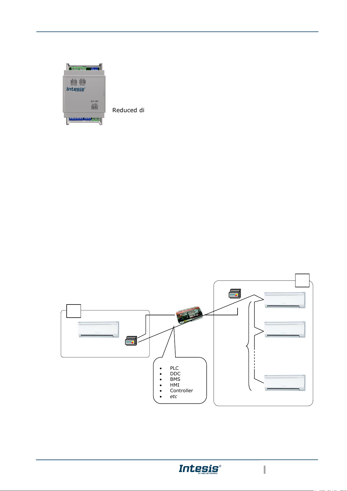
1 Presentation
The INMBSMID---I000 interface allows a complete and
natural integration of Midea air conditioners into Modbus
RTU (EIA-485) networks.
Compatible with VRF and Commercial lines.
Reduced dimensions. 93 x 53 x 58 mm
3.7” x 2.1” x 2.3”
• Quick and easy installation.
Mountable on DIN rail, wall, or even inside the indoor unit on some models of AC.
• External power required.
• Direct connection to Modbus RTU (EIA-485) networks. Up to 63 INMBSMID004I000 /
INMBSMID008I000 /INMBSMID032I000 devices can be connected on the same network.
INMBSMID---I000 is a Modbus slave device.
• Direct connection to the Midea XYE bus.
• Configuration from both on-board DIP-switches and Modbus RTU.
• Total Control and Supervision.
• Real states of the AC unit's internal variables.
• Allows simultaneous use of the AC’s remote controls and Modbus RTU.
• Individual control from 1 to 32 AC units with a single interface.
A Integration of single AC unit from independent XYE bus using INMBSMID001I000 interface
B Integration of multiple AC units in the same XYE bus using INMBSMID004I000 / INMBSMID008I000
/INMBSMID032I000 interface
• SCADA
• PLC
• DDC
• BMS
• HMI
•
Controller
• etc
Modbus RTU
Master device
INMBSMID001I000
Modbus RTU
EIA-485 network
INMBSMID---I000
Options
available:
N=1
N=4
N=8
N=32
AC Unit # 0
AC Unit # 1
AC Unit # N -1
B A Intesis® INMBSMID---I000
Page 6

User’s Manual r1.4 EN
© HMS Industrial Networks S.L.U - All rights reserved
This information is subject to change without notice
URL https://www.intesis.com
6 / 24
2 Connection
The interface comes with 3 plug-in terminal blocks of 2 poles.
The first (XY) is used to establish direct connection with the AC indoor unit. The second one
(V1V2) is used to provide power.
The third one (AB) is used to stablish connection with the Modbus RTU EIA-485 network.
2.1 Connect to the AC indoor unit
The INMBSMID---I000 connects directly to the Midea XYE bus. The cable for proper connection
is not provided with the interface. Maximum XYE bus length is 100 m (328.08 ft.).
Connector E, from the XYE bus, is not used to connect to the indoor unit or indoor units. The
XYE bus has specific polarity.
Depending on the number of AC units to control, the recommended connection’ methods can
be seen in Figure 2.1 and Figure 2.2.
NOTE: If a CCM Central Controller is present in the XYE bus, then the INMBSMID---I000
cannot be connected. Please, disconnect the CCM Central Controller for use of the gateway.
2.2 Connection to the EIA-485 bus
Connect the EIA-485 bus wires to the plug-in terminal block of the INMBSMID---I000 interface
and respect the polarity on this connection (A+ and B-).
Make sure that the maximum distance of the bus is 1,200 meters (3,937 ft.) in daisy chain set
up. Loop or star topologies are not allowed in the EIA-485 bus. A terminator resistor of 120Ω
must be present at each end of the bus to avoid signal reflections. The bus might need a failsafe biasing mechanism (see section 4.8 for more details).
2.3 Connection to the power supply
The INMBSMID---I000 interface must be powered from an external power supply.
Use an external 12V DC power supply connected to V1/V2 connector. The V1/V2 connection
has specific polarity (V1- y V2+).
Page 7
Intesis® INMBSMID---I000
User’s Manual r1.4 EN
© HMS Industrial Networks S.L.U - All rights reserved
This information is subject to change without notice
URL https://www.intesis.com
7 / 24
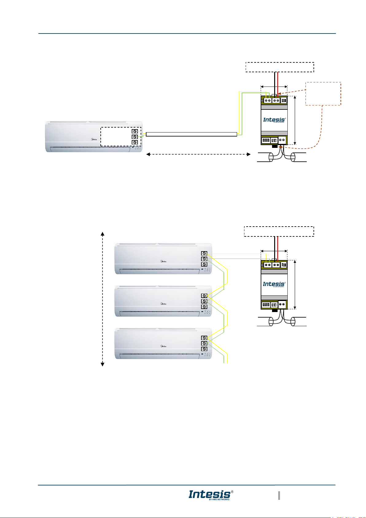
2.4 Connection diagrams
Figure 2.1 INMBSMID001I000 connection diagram
Figure 2.2 INMBSMID004I000 / INMBSMID008I000 /INMBSMID032I000 connection
diagram
NOTE: If a CCM Central Controller is present in the XYE bus, the INMBSMID---I000 cannot
be connected. Please, disconnect the CCM Central Controller for use of the gateway.
90 mm / 3.5”
MODBUS RTU
EIA-485
Bus
EIA485
A+ B-
X Y V1 V2
AC Unit Power
53 mm / 2.1”
For wall mounting,
extract the upper
and down staples
until you hear the
"click".
AC Indoor Unit
Max. 100 m / 328.08 ft
Connection to XYE bus.
Two wire cable.
X
Y
E
Internal
electronic
control board
External power supply 12V DC
(-) (+)
90 mm / 3.5”
MODBUS RTU
EIA-485
Bus
EIA485
A+ B-
X Y V1 V2
AC Unit Power
53 mm / 2.1”
AC Indoor Unit
Bus length
Max. 100 m / 328.08 ft
Connection to XYE bus.
Two wire cable.
External power supply 12V DC
(-) (+)
X
Y
E
X
Y
E
X
Y
E
AC Indoor Unit
AC Indoor Unit
Page 8

Intesis® INMBSMID---I000
User’s Manual r1.4 EN
© HMS Industrial Networks S.L.U - All rights reserved
This information is subject to change without notice
URL https://www.intesis.com
8 / 24
3 Quick Start Guide
1. Disconnect the air conditioning from the Mains Power.
2. Attach the interface close to the AC indoor unit (wall mounting) following the
instructions of the diagram above. Install it inside the AC indoor unit or an electrical
enclosure (respect the safety instructions provided by the AC manufacturer).
3. Connect the XYE bus between the interface and the AC indoor unit following the
instructions of the installation diagram respecting the polarity.
4. Connect the Modbus RTU (EIA-485) bus to the EIA485 A/B connector of the interface.
5. Connect the power cable between the interface and the Mains Power following the
instructions of the diagram. Screw each bare cable end in the corresponding V1/V2
terminals.
6. Check the DIP-Switch configuration of the Intesis interface and make sure it matches
the current installation’s parameters:
By default, the interface is set to:
▪ Modbus Slave Address ➔ 1
▪ Modbus baud rate ➔ 9600 bps
These parameters can be modified from SW3 and SW4 DIP-Switches.
All other switch positions are set at low level (Off position ) by default.
NOTE: All changes on the DIP-Switch configuration require a system power cycle to
be applied.
7. Connect the AC system to Mains Power.
IMPORTANT: The Intesis interface requires to be connected to the AC unit (powered)
to start the communication.
ON
ON
SW3
SW4
Page 9

Intesis® INMBSMID---I000
User’s Manual r1.4 EN
© HMS Industrial Networks S.L.U - All rights reserved
This information is subject to change without notice
URL https://www.intesis.com
9 / 24
4 Modbus Interface Specification
4.1 Modbus physical layer
INMBSMID---I000 implements a Modbus RTU (Slave) interface, to be connected to an EIA485 line. It performs an 8N2 communication (8 data bits, no parity and 2 stop bit) with several
available baud rates (2400 bps, 4800 bps, 9600 bps -default-, 19200 bps, 38400 bps, 57600
bps, 76800 bps and 115200 bps). It also supports 8N1 communication (8 data bits, no parity
and 1 stop bit).
4.2 Modbus Registers for INMBSMID001I000
All registers are type “16-bit unsigned Holding Register” and use the standard ModBus big
endian notation.
The indoor unit (IU) that is being controlled must have Unit Address 0. This address needs to
be set in the AC unit.
4.2.1 Control and status registers
Register Address
(protocol address)
Register Address
(PLC address)
R/W
Description
0
1
R/W
AC unit On/Off
▪ 0: Off
▪ 1: On
1
2
R/W
AC unit Mode 1
▪ 0: Auto (Default value)
▪ 1: Heat
▪ 2: Dry
▪ 3: Fan
▪ 4: Cool
2
3
R/W
AC unit Fan Speed 1
▪ 0: Auto (Default value)
▪ 1: SP1
▪ 2: SP2
▪ 3: SP3
3
4
R/W
AC unit Up/Down Vane Position 1
▪ 0: Off (Default value)
▪ 10: Swing
4
5
R/W
AC unit Temperature setpoint
1,2,3
▪ -32678 (Initialization value)
▪ 17..30 ºC (ºC/x10ºC)
▪ 63..86 ºF
5
6
R
AC unit Temperature reference
1,2,3
▪ -32678 (Initialization value)
▪ Ranges determined by the Manufacturer
of the AC indoor unit. (ºC/x10ºC/ºF)
6
7
R/W
Window Contact
▪ 0: Closed (Default Value)
▪ 1: Open
1
Available values will depend on the AC unit mode. Check the AC unit model functions in its User Manual to know the possible values
for this register.
2
Magnitude for this register can be adjusted to Celsius x 1ºC, Celsius x 10ºC (default) or Fahrenheit. See section 4.5 for more
information.
3
It is not possible turn the value shown in Fahrenheit to x10.
Page 10

Intesis® INMBSMID---I000
User’s Manual r1.4 EN
© HMS Industrial Networks S.L.U - All rights reserved
This information is subject to change without notice
URL https://www.intesis.com
10 / 24
Register Address
(protocol address)
Register Address
(PLC address)
R/W
Description
7
8
R/W
INMBSMID001I000 Disablement 4
▪ 0: INMBSMID001I000 enabled (Default)
▪ 1: INMBSMID001I000 disabled
8
9
R/W
Remote Control Disablement
4,5
▪ 0: Remote enabled (Default Value)
▪ 1: Remote disabled
9
10
R/W
AC unit Operation Time 4
▪ 0..65535 (hours). Counts the time the
AC unit is in “On” state.
10
11
R
AC unit Alarm Status
▪ 0: No alarm condition
▪ 1: Alarm condition
11
12
R
Error Code 6
▪ 0: No error active
▪ 65535 (-1 if it is read as signed value):
Error in the communication of
INMBSMID001I000 with the AC unit
▪ Any other error present, see the table at
the end of this document. (Section 7)
22
23
R/W
Indoor unit ambient temperature from
external sensor (at Modbus side)
1,2,3,7
▪ -32768: (Initialization value). No
temperature is being provided from an
external sensor.
▪ Any other: (ºC/x10ºC/ºF)
23
24
R
AC Real temperature setpoint
1,2,3,7
▪ -32678 (Initialization value)
▪ 17..30 ºC (ºC/x10ºC)
▪ 63..86 ºF
66
67
R
Return path Temperature
1,2,3
▪ -32768 (Initialization value)
▪ Ranges determined by the Manufacturer
of the AC indoor unit. (ºC/x10ºC/ºF)
97
98
R/W
Block Periodic Sendings
4,8,9
▪ 0: Non-blocked (Default value)
▪ 1: Blocked
4
This value is stored in non-volatile memory
5
This register blocks the Remote Controller’s communication installed in the MD-RC bus (if this one has been installed).
6
See section 7 for possible error codes and their explanation
7
See section 4.4 for more information
8
If the register is configured as “0: Non-blocked”, all commands received from Modbus will be sent to the AC system. If “1: Blocked”,
commands from Modbus will only be sent to the AC system if they differ from the previous value (values sent on change).
9
This register applies to firmware version 1.0 onwards
Page 11

Intesis® INMBSMID---I000
User’s Manual r1.4 EN
© HMS Industrial Networks S.L.U - All rights reserved
This information is subject to change without notice
URL https://www.intesis.com
11 / 24
4.2.2 Configuration Registers
Register Address
(protocol address)
Register Address
(PLC address)
R/W
Description
13
14
R/W
“Open Window” switch-off timeout 10
▪ 0..30 (minutes)
▪ Factory setting: 30 (minutes)
14
15
R
Modbus RTU Baud rate
▪ 2400bps
▪ 4800bps
▪ 9600bps (Default Value)
▪ 19200bps
▪ 38400bps
▪ 57600bps
▪ 76800bps
▪ 115200bps
15
16
R
Device's Modbus Slave address
▪ 1..63
21
22
R
Max number of fan speeds
49
50
R
Device ID: 0x2200
50
51
R
Software version
99
100
W
Reset/Reboot device
▪ 1: Reset
2031
2032
R
Capacity 11
▪ 1: INMBSMID001I000 (1 Indoor Unit)
10
Once window contact is open, a count-down to switch off the AC Unit will start from this configured value.
11
The value of this register depends on the N value (being N the number of max. indoor units that admits INMBSMID---I000)
Page 12

Intesis® INMBSMID---I000
User’s Manual r1.4 EN
© HMS Industrial Networks S.L.U - All rights reserved
This information is subject to change without notice
URL https://www.intesis.com
12 / 24
4.3 Modbus Registers for INMBSMID004I000 /
INMBSMID008I000 /INMBSMID032I000
All registers are type “16-bit unsigned Holding Register”, and they use the Modbus big endian
standard notation.
Important note: match Midea addressing before controlling from Modbus
All indoor units must be addressed in the range 0…63 in the Midea system. The register
“Indoor Unit Address assignation” R/W, sets the indoor unit address to control with the
gateway. Assigned address in this register must match the address set for every unit in the
Midea system.
4.3.1 Global Control and status registers
These registers apply to each Indoor Unit connected to the interface.
Register Address
(protocol address)
Register Address
(PLC address)
R/W
Description
0
1
W
AC unit On/Off Global
▪ 0: Off
▪ 1: On
1
2
W
AC unit Mode Global 12
▪ 0: Auto
▪ 1: Heat
▪ 2: Dry
▪ 3: Fan
▪ 4: Cool
2
3
W
AC unit Fan Speed Global 12
▪ 0: Auto
▪ 1: SP1
▪ 2: SP2
▪ 3: SP3
3
4
W
AC unit Vane Position Global 12
▪ 0: Auto/Stop (Default value)
▪ 10: Swing
4
5
W
AC unit Temperature setpoint Global
12,13
▪ -32678 (Initialization value)
▪ 17..30 ºC (ºC/x10ºC)
▪ 63..86 ºF
8
9
W
Remote lock
14,15
▪ 0: Off (Default value)
▪ 1: On
12
Available values will depend on the AC unit mode. Check the AC unit model functions in its user manual to know the possible values
for this register.
13
Magnitude for this register can be adjusted to Celsius x 1ºC, Celsius x 10ºC (default) or Fahrenheit.
14
This value is stored in a non-volatile memory
15
This register blocks the Remote Controller’s communication installed in the MD-RC bus (if this one has been installed).
Page 13

Intesis® INMBSMID---I000
User’s Manual r1.4 EN
© HMS Industrial Networks S.L.U - All rights reserved
This information is subject to change without notice
URL https://www.intesis.com
13 / 24
4.3.2 Individual Control and status registers
These registers apply to each indoor unit connected to the interface. Notice that “n” stands
for the Indoor Unit’s index number (0…31) in the interface. You can change the address
assigned to the index “n” by writing in register ‘1000 + 20*n + 9’ the value of the desired
IU’s address (0…63).
Example: given a INMBSMID004I000 (the interface can control up to 4 indoor units), “n”
stands for 0, 1, 2 and 3 and this index number is not related to the address inside the Midea
system, which is managed in the register ‘1000 + 20*n + 9’.
Register Address
(protocol address)
Register Address
(PLC address)
R/W
Description
(1000 + 20*n + 0)
(1000 + 20*n + 1)
R/W
AC unit On/Off
▪ 0: Off
▪ 1: On
(1000 + 20*n + 1)
(1000 + 20*n + 2)
R/W
AC unit Mode 16
▪ 0: Auto (Default value)
▪ 1: Heat
▪ 2: Dry
▪ 3: Fan
▪ 4: Cool
(1000 + 20*n + 2)
(1000 + 20*n + 3)
R/W
AC unit Fan Speed 16
▪ 0: Auto (Default value)
▪ 1: SP1
▪ 2: SP2
▪ 3: SP3
(1000 + 20*n + 3)
(1000 + 20*n + 4)
R/W
AC unit Up/Down Vane Position 16
▪ 0: Off (Default value)
▪ 10: Swing
(1000 + 20*n + 4)
(1000 + 20*n + 5)
R/W
AC unit Temperature setpoint
16,17,18
▪ -32678 (Initialization value)
▪ 17..30 ºC (ºC/x10ºC)
▪ 63..86 ºF
(1000 + 20*n + 5)
(1000 + 20*n + 6)
R
AC unit Temperature reference
16,17,18
▪ -32678 (Initialization value)
▪ Ranges determined by the Manufacturer
of the AC indoor unit. (ºC/x10ºC/ºF)
(1000 + 20*n + 6)
(1000 + 20*n + 7)
R
AC Alarm status
▪ 0: No Alarm
▪ 1: Alarm
(1000 + 20*n + 7)
(1000 + 20*n + 8)
R
AC Error Code 19
▪ 0: No error active
▪ 65535 (-1 if it is read as signed value).
Error in the communication of
INMBSMID004I000 /
INMBSMID008I000 /
INMBSMID032I000 with the AC unit
▪ Any other error present, see the table at
the end of this document.
(1000 + 20*n + 8)
(1000 + 20*n + 9)
R/W
Remote lock
20,21
▪ 0: Off (Default value)
▪ 1: On
16
Available values will depend on the AC unit mode. Check the AC unit model functions in its user manual to know the possible values
for this register.
17
Magnitude for this register can be adjusted to Celsius x 1ºC, Celsius x 10ºC (default) or Fahrenheit.
18
It is not possible turn to x10 the value shown in Fahrenheit.
19
See section 7 for possible error codes and their explanation.
20
This value is stored in a non-volatile memory
21
This register blocks the Remote Controller’s communication installed in the MD-RC bus (if this one has been installed).
Page 14

Intesis® INMBSMID---I000
User’s Manual r1.4 EN
© HMS Industrial Networks S.L.U - All rights reserved
This information is subject to change without notice
URL https://www.intesis.com
14 / 24
(1000 + 20*n + 9)
(1000 + 20*n +10)
R/W
Indoor Unit Address assignation in n
▪ Address range: 0..63
Configuration Registers
Register Address
(protocol address)
Register Address
(PLC address)
R/W
Description
2000
2001
R
Device ID: 0x2200
2031
2032
R
Capacity 22
▪ 4: INMBSMID004I000 (4 Indoor Units)
▪ 8: INMBSMID008I000 (8 Indoor Units)
▪ 32: INMBSMID0032I000 (32 Indoor Units)
2040
2041
R
Modbus RTU Baud rate
▪ 2400bps
▪ 4800bps
▪ 9600bps (Default)
▪ 19200bps
▪ 38400bps
▪ 57600bps
▪ 76800bps
▪ 115200bps
2041
2042
R
Device's Modbus Slave address
▪ 1..63
2050
2051
R
Software version
2099
2100
W
Reset/Reboot device
▪ 1: Reset
22
The value of this register depends on the N value (being N the number of max. indoor units that admits INMBSMID004I000 /
INMBSMID008I000 / INMBSMID0032I000)
Page 15

Intesis® INMBSMID---I000
User’s Manual r1.4 EN
© HMS Industrial Networks S.L.U - All rights reserved
This information is subject to change without notice
URL https://www.intesis.com
15 / 24
4.4 Considerations on Temperature Registers
The next information refers to INMBSMID001I000 and may not apply to INMBSMID004I000
/ INMBSMID008I000 /INMBSMID032I000.
• AC unit temperature setpoint (R/W)
(register 4 – in Protocol address / register 5 – in PLC address):
This is the adjustable temperature setpoint value required by the user.
This register can be read (Modbus function 3 or 4) or written (Modbus functions 6 or
16). If present, a remote controller connected to the Midea indoor unit will report the
same temperature setpoint value as this register, but only will happen when no AC
unit´s external reference is provided from INMBSMID001I000 (see detail for register
22/23 below).
• AC unit temperature reference (R)
(register 5 – in Protocol address / register 6 – in PLC address):
This register reports the temperature that is currently used by the Midea indoor unit
as the reference of its own control loop. Depending on the configuration of the indoor
unit, this value can be the temperature reported by the sensor on the return path of
the Midea indoor unit or the sensor of its remote controller. It is a read-only register
(Modbus functions 3 or 4).
• AC unit external temperature reference (Modbus) (R/W)
(register 22 – in Protocol address / register 23 – in PLC address):
This register allows to provide an external temperature’s value from the Modbus side.
The Midea indoor unit does not allow to provide an external temperature to be used
as a reference of the control loop of the AC indoor unit. In order to overcome this
limitation and enable the usage of an external temperature sensor (i.e. from Modbus
side), INMBSMID001I000 applies the following mechanism (only if “external
temperature’s reference” is being used):
o After a couple of values have been entered in the “AC unit external
temperature’s reference” (register 22/23) and “AC unit temperature set point”
(register 4/5), INMBSMID001I000 is going to estimate the chosen temperature
differences (e.g. if a “temperature setpoint (register 4/5)” of 22ºC, and an
“external temperature reference (register 22/23)” of 20ºC are entered,
INMBSMID001I000 will assume that the user is demanding a +2ºC increase in
temperature).
o By knowing at any time the ambient temperature currently used by the indoor
unit to control its own operation (register 5/6), INMBSMID001I000 can
calculate the required temperature setpoint needed to apply the
decrease/increase on the real temperature and reach the temperature chosen
by the user (following the example above, if INMBSMID001I000 reads an
“ambient temperature” (register 5/6) of 24ºC in the indoor unit, it will apply a
final setpoint of 24ºC + 2ºC = 26ºC).
o At this moment, each time that INMBSMID001I000 detects a change on the
ambient temperature reported by the indoor unit (register 5/6), it will also
change the required setpoint, in order to keep the temperature required by the
user at any time. If we follow the last example, if INMBSMID001I000 receives
a new temperature´s value coming from the indoor unit of 25ºC,
INMBSMID001I000 will automatically adjust the temperature setpoint required
of the AC indoor unit to 25ºC + 2ºC = 27ºC).
Page 16

Intesis® INMBSMID---I000
User’s Manual r1.4 EN
© HMS Industrial Networks S.L.U - All rights reserved
This information is subject to change without notice
URL https://www.intesis.com
16 / 24
o In general, INMBSMID001I000 is constantly applying the “Virtual Temperature”
formula:
SAC = Su – ( Tu – T
AC
)
Where:
SAC - setpoint value currently applied to the indoor unit
Su - setpoint value written at Modbus side (register 4/5)
Tu - external temperature reference written at Modbus side (register 22/23)
TAC - ambient temperature that the indoor unit is using as the reference of its
own control loop (register 5/6)
When INMBSMID001I000 detects a change in any of the values of
{ Su , Tu , TAC }, it will send the new setpoint (SAC) to the indoor unit.
o After the startup, the value for “external temperature’s reference” (register
22/23) has a value -32768 (0x8000). This value means that no external
temperature reference is being provided through INMBSMID001I000. In this
scenario, the setpoint value shown in register 4/5 will always be the same as
the current setpoint value of the indoor unit. AC indoor unit will use its own
return path temperature sensor as reference for its control loop.
o When the mechanism of “Virtual Temperature” is applied. The temperature
setpoint’s value shown by the Remote Controller from Midea connected to the
indoor unit shall show a different value from the value shown in register 4/5.
Instead it shall show the calculated Virtual Setpoint.
• AC Real temperature setpoint (R)
(register 23 – In Protocol address / register 24 – in PLC address):
As detailed on the previous point, the real temperature setpoint in the indoor unit and
the temperature setpoint requested from INMBSMID001I000 might differ (when a
value in register 22/23 – “external temperature reference” is entered). This register
always informs about the current temperature setpoint, used by the indoor unit – this
is the actual setpoint that will be shown by an additional remote controller if present.
Moreover, notice that temperature’s values of all these three registers are expressed according
to the temperature’s format configured through its onboard DIP-Switches. The following
formats are possible:
• Celsius value: Value in Modbus register is the temperature value in Celsius (i.e.
a value “22” in the Modbus register must be interpreted as 22ºC).
• Decicelsius value: Value in Modbus register is the temperature value in
decicelsius (i.e. a value “220” in the Modbus register must be interpreted as
22.0ºC).
• Fahrenheit value: Value in Modbus register is the temperature value in
Fahrenheit (i.e. a value “72” in the Modbus register must be interpreted as 72ºF
(~22ºC).
Page 17

Intesis® INMBSMID---I000
User’s Manual r1.4 EN
© HMS Industrial Networks S.L.U - All rights reserved
This information is subject to change without notice
URL https://www.intesis.com
17 / 24
4.5 DIP-switch Configuration Interface
All the configuration values on INMBSMID---I000 can be written and read from Modbus
interface. Otherwise, some of them can also be setup from its on-board DIP-switch interface.
The device has DIP-switches SW1, SW3 and SW4 on the following locations:
The following tables apply to the interface’s configuration
through DIP-switches:
SW1 – AC indoor unit’s features
Table 4.1 SW1: AC indoor unit´s features
SW1-P1..4
Description
AC Unit does not have AUTO mode (Default value)
AC Unit has AUTO mode
AC Unit does not have DRY mode (Default value)
AC Unit has DRY mode
AC Unit does not have fan AUTO mode (Default value)
AC Unit has fan AUTO mode
AC Unit has 2 fan speeds (Default value)
AC Unit has 3 fan speeds
SW3
SW4
SW3 SW4
EIA485
A+ B-
X Y
AC Unit
SW1
ON
1 2 3 4
SW1*
ON
ON
1 2 3 4
1 2 3 4 5 6 7 8
SW3
SW4
ON
ON
ON
ON
ON
ON
V1 V2
Power
ON
ON
*Configuration of SW1 is only
available in case of
INMBSMID001I000. It is not
available in case of
INMBSMID004I000 /
INMBSMID008I000
/INMBSMID032I000.
You should leave switches of
SW1 in default position in case
of INMBSMID004I000 /
INMBSMID008I000
/INMBSMID032I000.
Options available:
N=1
N=4
N=8
N=32
Page 18

Intesis® INMBSMID---I000
User’s Manual r1.4 EN
© HMS Industrial Networks S.L.U - All rights reserved
This information is subject to change without notice
URL https://www.intesis.com
18 / 24
SW3/SW4 – Baud rate configuration
SW3-P7..8
SW4-P3
Description
2400bps
4800bps
9600bps (Default value)
19200bps
38400bps
57600bps
76800bps
115200bps
Table 4.2 SW3-SW4: Modbus baud rate
SW4 – Degrees/Decidegrees (x10), temperature magnitude (ºC/ºF) and EIA-485 termination
resistor.
Table 4.3 SW4: Temperature and termination resistor configuration
SW4-P1..2-4
Description
Temperature values in Modbus register are represented in degrees (x1) (Default value)
Temperature values in Modbus register are represented in decidegrees (x10)
Temperature values in Modbus register are represented in Celsius degrees (Default value)
Temperature values in Modbus register are represented in Fahrenheit degrees
EIA-485 bus without termination resistor (Default value)
Internal termination resistor of 120Ω connected to EIA-485 bus
ON
ON
ON
ON
ON
ON
ON
ON
ON
ON
ON
ON
ON
ON
ON
ON
ON
ON
ON
ON
ON
ON
Page 19

Intesis® INMBSMID---I000
User’s Manual r1.4 EN
© HMS Industrial Networks S.L.U - All rights reserved
This information is subject to change without notice
URL https://www.intesis.com
19 / 24
SW3 – Modbus Slave address
Table 4.4 SW3: Modbus Slave address
Add SW3-P1..6
Add SW3-P1..6
Add
SW3-P1..6
Add
SW3-P1..6
Add
SW3-P1..6
0
13
26
39
52
1
14
27
40
53
2
15
28
41
54
3
16
29
42
55
4
17
30
43
56
5
18
31
44
57
6
19
32
45
58
7
20
33
46
59
8
21
34
47
60
9
22
35
48
61
10
23
36
49
62
11 24 37 50 63
12 25 38 51
ON
ON
ON
ON
ON
ON
ON
ON
ON
ON
ON
ON
ON
ON
ON
ON
ON
ON
ON
ON
ON
ON
ON
ON
ON
ON
ON
ON
ON
ON
ON
ON
ON
ON
ON
ON
ON
ON
ON
ON
ON
ON
ON
ON
ON
ON
ON
ON
ON
ON
ON
ON
ON
ON
ON
ON
ON
ON
ON
ON
ON
ON
ON
ON
Page 20

Intesis® INMBSMID---I000
User’s Manual r1.4 EN
© HMS Industrial Networks S.L.U - All rights reserved
This information is subject to change without notice
URL https://www.intesis.com
20 / 24
4.6 Implemented Functions
INMBSMID---I000 implements the following standard Modbus functions:
▪ 3: Read Holding Registers
▪ 4: Read Input Registers
▪ 6: Write Single Register
▪ 16: Write Multiple Registers (Despite this function is allowed, the interface does not
allow to write operations on more than 1 register with the same request, this means
that length field should always be 1 when this function is being used for writing)
4.7 Device LED indicator
The device includes LED indicators to show all the possible operational states. In the following
table you will find the possible indication combinations and its meaning.
L1 (green LED)
Device status
LED indication
ON / OFF Period
Description
During faulty
operation
LED blinking
500ms ON / 500ms OFF
Communication error
During normal
operation
LED flashing
100ms ON / 1900ms OFF
Normal operation (configured and
working properly)
L2 (red LED)
Device status
LED indication
ON / OFF Period
Description
During faulty
operation
LED Pulse
3sec ON / --- OFF
Under voltage occurs.
L1 (green LED) & L2 (red LED)
Device status
LED indication
ON / OFF Period
Description
During normal
operation
LED Pulse
5sec ON / --- OFF
Device Start-up
During faulty
operation
LED alternatively
blinking
500ms ON / 500ms OFF
Flash checksum not OK
Page 21

Intesis® INMBSMID---I000
User’s Manual r1.4 EN
© HMS Industrial Networks S.L.U - All rights reserved
This information is subject to change without notice
URL https://www.intesis.com
21 / 24
4.8 EIA-485 bus. Termination resistors and Fail-Safe Biasing
mechanism
EIA-485 bus requires a 120Ω terminator resistor at each end of the bus to avoid signal
reflections.
In order to prevent fail status detections by the receivers, which are "listening" the bus, when
all the transmitters’ outputs are in three-state (high impedance), a fail-safe biasing mechanism
is required. This mechanism provides a safe status (a correct voltage level) in the bus when all
the transmitters’ outputs are in three-state.
The INMBSMID---I000 device includes an on-board terminator resistor of 120Ω that can be
connected to the EIA-485 bus by using DIP-switch SW4.
Some Modbus RTU EIA-485 Master devices can provide also internal 120Ω terminator resistor
and/or fail-safe biasing. Check the technical documentation of the Master device connected to
the EIA-485 network in each case.
Page 22

Intesis® INMBSMID---I000
User’s Manual r1.4 EN
© HMS Industrial Networks S.L.U - All rights reserved
This information is subject to change without notice
URL https://www.intesis.com
22 / 24
5 Electrical and Mechanical features
Enclosure
Plastic, type PC (UL 94 V-0)
Net dimensions (dxwxh):
93 x 53 x 58 mm / 3.7” x 2.1” x 2.3”
Color: Light Grey. RAL 7035
Operation
Temperature
0ºC to +60ºC
Weight
85 g.
Stock
Temperature
-20ºC to +85ºC
Mounting
Wall
DIN rail EN60715 TH35.
Operational
Humidity
<95% RH, non-condensing
Terminal Wiring
(for lowvoltage signals)
For terminal: solid wires or stranded wires
(twisted or with ferrule)
1 core: 0.5mm2… 2.5mm2
2 cores: 0.5mm2… 1.5mm2
3 cores: not permitted
Stock Humidity
<95% RH, non-condensing
Modbus RTU
port
1 x Serial EIA485 Plug-in screw terminal block
(2 poles)
A, B
Compatible with Modbus RTU EIA-485 networks
Isolation
voltage
1500 VDC
AC unit port
1 x XYE bus Plug-in screw terminal block
(2 poles):
X, Y
Compatible with Midea networks
Isolation
resistance
1000 MΩ
Power port
1 x V1 V2 Power screw terminal block
(2 poles):
V1, V2
Switch 1
(SW1)
1 x DIP-Switch for AC features
Protection
IP20 (IEC60529)
Switch 3
(SW3)
1 x DIP-Switch for Modbus RTU settings
LED indicators
2 x Onboard LED - Operational
status
Switch 4
(SW4)
1 x DIP-Switch for extra functions
EIA-485
Port
DIP
Switch SW3
LED
indicators
DIP
Switch SW4
DIP
Switch SW1
Power
connector
AC Unit
connector
Page 23

Intesis® INMBSMID---I000
User’s Manual r1.4 EN
© HMS Industrial Networks S.L.U - All rights reserved
This information is subject to change without notice
URL https://www.intesis.com
23 / 24
6 List of supported AC Unit Types
A list of Midea indoor unit model´s references compatible with INMBSMID---I000 and its
available features can be found in:
https://www.intesis.com/docs/compatibilities/inxxxmid0xxi000_compatibility
Page 24

Intesis® INMBSMID---I000
User’s Manual r1.4 EN
© HMS Industrial Networks S.L.U - All rights reserved
This information is subject to change without notice
URL https://www.intesis.com
24 / 24
7 Error Codes
Error
Code
Error in
Remote
Controller
Error description
0
N/A
No active error
1
E0
Phase error or error in the phase sequence
2
E1
Communication error
3
E2
T1 sensor error
4
E3
T2A sensor error
5
E4
T2B sensor error
6
E5
T3 temperature and T4 temperature Compressor discharge temperature sensors error
7
E6
Zero cross error detection
8
E7
EEPROM memory error
9
E8
Indoor fan speed out of control
10
E9
Communication error between the main panel and the visualization panel
11
EA
Compressor’s current overload error (4 times)
12
EB
Inverter module protection
13
EC
Cooling error
14
ED
Outdoor unit fault protection
15
EE
Water level fault detection
16
EF
Other errors
101
P0
Vaporizer temperature protection
102
P1
Thawing or cold air protection
103
P2
Condenser high temperatures protection
104
P3
Compressor temperature protection
105
P4
Evacuation duct temperature protection
106
P5
Discharge high pressure protection
107
P6
Discharge low pressure protection
108
P7
Current overload or under load protection
109
P8
Compressor’s current overload protection
110
P9
Reserved
111
PA
Reserved
112
PB
Reserved
113
PC
Reserved
114
PD
Reserved
115
PE
Reserved
116
PF
Other protection measures
65535
(-1)
N/A
Error in the communication of INMBSMID---I000 with the AC unit
-100
N/A
License error / Indoor units not supported by current license
-200
N/A
Overconsumption error in EXY bus
In case you detect an error code not listed, contact your nearest Midea technical support
service.
 Loading...