

Inteset Thin Mini-ITX Case Assembly Instructions
(Model # INT-TX482-1U)
Please read these instructions before you assemble the case and its components. Also, view the Assembly Tutorial on
YouTube at: http://youtu.be/3fPapYFwK2Q. You may also be interested in the Inteset PC-IRS5-01 IR Receiver Installation
Tutorial that shows how to install the Receiver in this case on YouTube at: http://youtu.be/oS98E32VhB4
Prepare the MB for Installation
1. Install the CPU onto the MB and apply grey CPU grease. Check out this link for a detailed explanation of how to
install a CPU. http://www.intel.com/support/processors/sb/CS-032258.htm
2. Install the CPU cooler, if it is not built into your motherboard already.
3. If your system needs a CPU Cooler, we have tested and recommend the Dynatron K199 or one similar for your CPU
which has a low profile and very good cooling properties. It also has a side exhausting fan which is required for this
case. Do not use a fan that requires a top vent in the case cover.
4. Install the CPU Cooler over the CPU and onto the MB. Be sure that the fan exhaust is facing the left side of the case
as viewed from the front.
5. Insert the screws into the anchor plates provided by the cooler manufacturer. Be sure that the anchor plates do not
make contact with any board components that could cause a short when operating.
6. If you are installing a Dynatron K2 or similar with a push-pin mounting be sure that these are solidly installed.
7. Plug the CPU Cooler fan connector onto the MB fan connector marked “CPU Fan” on your MB.
Install the Motherboard (MB)
8. Install the MB into the case using (4) screws provided after you have inserted the I/O plate for your MB in the back of
the case. (Note: Please be very careful when installing the MB in the case near the Power Button cables. We
have had reports of cable damage during installation if the MB hits the connection point of the power switch
and the attached cables)
9. Plug the rear case fan cable onto the MB fan connector. (Usually labeled “SYS Fan” on the MB)
10. If you have purchased our IRS5-01 IR Receiver or our USB IR Receiver, install it onto the shelf at the front of the
case using the two nylon standoffs under the board (or one for the USB IR) as well as the small nylon washer(s) on
top of the board and screw the fasteners provided into the IR shelf. The connectors should face the MB.
11. Be sure that the IR Receiver’s solder feet on the bottom of the receiver do not touch the shelf directly. If there is any
issue with this, place a piece of electrical tape on the top surface of the IR shelf prior to installing the IR.
12. Install the cables provided with the IR Receiver per the instructions provided.
13. Install the FP Audio cable onto the Audio header and the FP USB Cable onto a double USB header of the MB.
14. Install the FP Power Switch and LED cables onto the FP Header of the MB. If you are installing the IRS5-01 IR
Receiver be sure to follow the installation instructions that came with the IR Receiver for these cables so that both
the IRS5-01 and the Power Switch operate correctly.
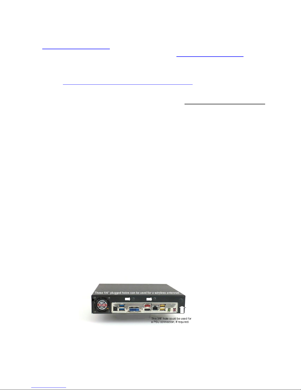
The larger plugged hole shown above right can be used for a PicoPSU jack or the Power Adapter jack for the PC-IRS5-01IR Receiver. If
you are installing both devices you will need to enlarge one of the wireless antenna ¼” holes as shown above.
Page 1
Inteset Thin Mini-ITX Case Assembly Instructions
(Model # INT-TX482-1U)
Power Supply Installation
15. Most thin mini-ITX MBs require a 19 volt external adapter for the PSU already on the MB.
16. If you are installing a Pico-PSU on your MB, route the adapter jack to the back of the case and mount it through the
larger hole in the case back panel. If you have both a Pico-PSU and our IRS5-01 you will have to enlarge one of the
smaller holes for one of the jacks from those devices.
Prepare and Install the Notebook HDD or Solid State Drive (SSD)
17. The HDD/SSD is mounted on the Black custom bracket provided.
18. Install the HDD/SSD on the top surface of the bracket with the connectors facing the double support end of the
bracket using the screws provided with the drive.
19. Use the HDD/SSD power cable that is supplied with your MB. You must use the cable with female SATA connectors
on the drive and on the MB for the bracket and for the case cover to fit properly (See the pictures below). If the cable
that comes with your MB does not work, go to shop.inteset.com. We can provide a cable that will fit the case.
20. Install the short BLACK mini SATA data cable, as supplied, to the SATA data connector on the MB.
21. Thread the power cable and the data cable through the opening in the end of the bracket.
22. Install the bracket with the HDD/SSD into the case. Be sure that no cables are under the bracket where it is to be
attached to the floor of the case.
23. Attach the bracket to the case using the (2) screws that attached the bracket when you opened the case package.
Connect the SATA power and data cables to the drive.
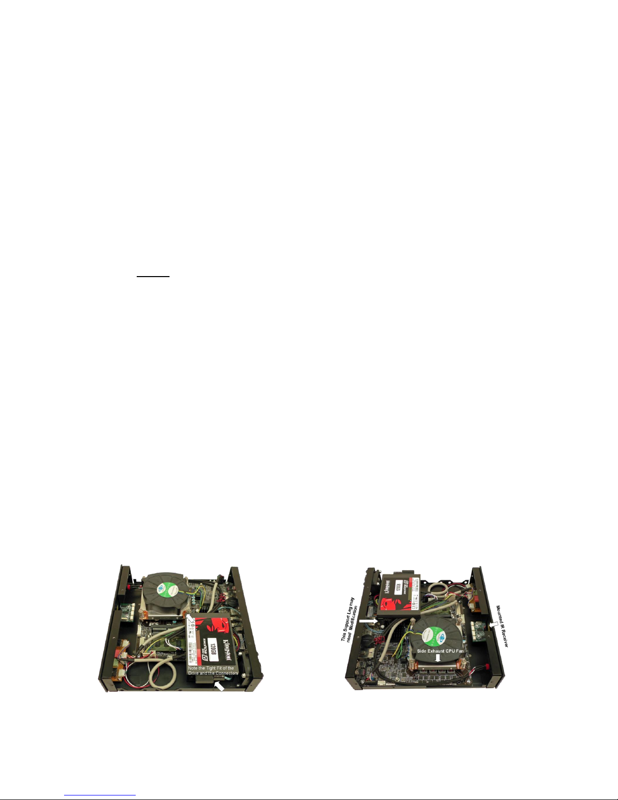
24. The insulated Support Leg of the bracket should rest on the MB. If there is a MB component in the way of the Leg,
the Leg can be bent or even cut off to accommodate the component. If you bend or cut off the Leg be sure to insulate
the bare metal with electrical tape. (See the picture below)
25. The drive will fit between the power supply and MB back plane connector pods and it will be close to touching the
CPU cooling fan case as pictured below.
Install the aluminum cover
26. Wire tie the cables inside the case as neat as possible to allow good air flow through the side vents for the rear fan
and the CPU cooler to operate efficiently.
27. Install the case cover. It should fit easily over the installed components. Do not force the cover on. Adjust the
components or the cables to provide a good fit. If there is a fit problem with the HDD Cable we can provide one that
will fit under the cover.
28. Be sure that there is good air flow through the air vents as seen with the cover installed.
29. Install the 10 screws provided into the cover. These should screw in easily. Do not force any screw as it will strip the
threads.
Cases with components installed
Page 2

Inteset Thin Mini-ITX Case Assembly Instructions
(Model # INT-TX482-1U)
This case will accommodate either our PC-IRS5-01 IR Receiver or our Internal USB IR Receiver
Front View of Case as Shipped Rear View of Case as Shipped
VESA Mount Holes on Bottom of the Case Case as Shipped with the Cover Removed
Rackmount Faceplate with Two Cases Rackmount Faceplate with One Case & Cover Plate
(Double Faceplate Sold Separately at www.shop.inteset.com)
Page 3
 Loading...