

interWAVE WAVEXpress/BTS Installation And Commissioning Manual

WAVEXpress/BTS
Installation and
Commissioning
Guide
Release 3.3
interWAVE
Part Number 680075-00
COMMUNICATIONS
1/99 Revision A

ii WAVEXpress/BTS Installation and Commissioning Guide
Release 3.3, Revision A 1/99

The products described in this document are products of interWAVE Comm unications, Inc. or its licensers. This
document represents confidential information . No part of this document may be photocopied, re produced, translated,
transferred, disclosed or otherwise provided to third parties without the prior written consent of an officer of
interWAVE Communications, Inc.
Release 3.3, Revision A (January 1999)
This document applies to the interW AVE Communications International, Inc. system release 3.3 of the WAVEXpress/
BTS and to all subsequent versions and releases of the hardware or software unless otherwise indicated in a new
version or an update package for t his edition.
Publications are stocked at the address given below. Requests should be addressed to:
Technical Publications Department
656 Bair Island Road, Suite 108
Redwood City, CA 94063
Fax: 650.261.6220
interWAVE Communications, Inc. reserves the right to make changes to any products described herein at any time
without notice. interWAVE Communications, Inc. does not assume any responsibility or liability arising out of the
application or use of any product described herein, except as expressly agreed to in writing by interWAVE
Communications International, Inc. nor does the purchase or use of a product from interWAVE Communications
International, Inc. c onvey a license under any pate nt rights, c opyrights, tra demark rights, or any other of the inte llectual
property rights of interWAVE Communications International, Inc. or third parties.
The software described in this document is furnished under a license agreement or nondisc losu re agreem ent . The
software may be used or copied only in accordance with the terms of the agreement. It is a violation of interWAVE
Communications, Inc. proprietary rights to copy the software on any medium except as specifically allowed in the
license or nondisclosure agreement.
United States Federal Communications Commissio n Requir ed User Information
This equipment complies with Part 68 of the FCC rules. Lo cated on the equipment is a label that contains , among other
information, the FCC registration number. If requested, this information must be provided to the telephone company.
This equipment cannot be used on the telephone company- provided coi n servic e. Connection t o Part y Li ne Ser vice is
subject to State Ta ri ffs.
If this equipment causes harm to the telephone n e twork, the telephone company will notify you in adva n ce that
temporary discontinuance of service may be required. If advance notice isn’t practical, the telephone company will
notify the customer as soon as possible. Also, you will be advised of your right to file a com p laint with the FCC if you
believe it is necessary.
The telephone company may make changes in its facil ities, eq uipment, operatio ns, of proce dures that could affect the
operation of the equipment. If this happens, the telephone company will provide advance notice in order for you to
make the necessary modifications in order to maintain uninterrupted service.
iii
Release 3.3, Revision A 1/99

If trouble is experienced with this equipm ent , please contact:
interWAVE Communications, Inc.
656 Bair Island Road, Suite 108
Redwood City, CA 94063
Phone: 650.482.2100
If the trouble is causing harm to the telephone network, the telephone company may request you to remove the
equipment from the network until the problem is resolved.
It is recommended that the customer install an AC surge arrester in the AC outlet to which that device is connected.
This is to avoid damaging the equipment caused by local lightening strikes and other electrical surges.
This equipment uses the following USOC jacks and codes:
Model Name Facility Interface Code Service Order Code Jack Type
340122 04DU9-BN 6.ON RJ-48C
340122 04DU9-DN 6.ON RJ-48C
340122 04DU9-1KN 6.ON RJ-48C
340122 04DU9-1SN 6.ON RJ-48C
340122 04DU9-1zN 6.ON RJ-48C
NOTE: This equipment has been tested and found to comply with the limits for a Class A digital device, pursuant to
Part 15 of the FCC Rules. These limits are designed to provide reasonable protection against harmful interference
when the equipment is operated in a commercial environment. This equipment generates, uses and can radiate radio
frequency energy and, if not installed and used in accordance with the instruction manual, may cause harmful
interference to radio communications. Operation of this equipment in a residential area is likely to cause harmful
interference in which case the user will be required to correct the interference at his own expense.
Changes of modifications not expressly approved by interWAVE Communications, Inc. can void the user’s authority
to operate the equipment.
The 1900MHz WAVEXpress Series M50 complies with Part 24 of the FCC Rules.
iv WAVEXpress/BTS Installation and Commissioning Guide
Release 3.3, Revision A 1/99

Industry Canada Required User Information
CP-O1, Issue 8, Part 1, Section 14.1
NOTICE: The Industry Canada label identifies certified equipment. This certification means that the equipment meets
certain telecommunications n etw ork prot ective, operational and safety requirements as prescribed in th e appropr iate
Terminal Equipment Technical Requirements document(s). The Department does not guarantee the equipm ent will
operate to the user’s sat isfaction.
Before installing this equipment, users should ensure that it is permissible to be connected to the faci lities of the local
telecommunications company. The equipment must als o be installed using an acceptable method of connection. The
customer should be aware that complianc e with the above conditions may not p revent de gradation of servic e in some
situations.
Repairs to certified equipment should be coordinated by a representative designated by the supplier. Any repairs or
alterations made by the user to this equipment, or equipment malfunctions, may give the telecommunications company
cause to request the user to disconnect the equipment.
Users should ensure for their own protec tion that the electrical ground c onnections of the power utility , telephone lines
and internal metallic water pipe system, if present, are connected together. T his precaution may be particularly
important in rural areas.
CAUTION: Users should not attempt to make such connect ions themselves, but should cont act the appropriate electr ic
inspection authority, or electrician, as appropriate.
The standard connecting arrangement (telephone jack type) for this equipment is CA81A.
CP-01, Issue 8, Part 1, Section 14.2
NOTICE: The Ringer Equivalence Number (REN) assigned to each terminal device provides an indication of the
maximum number of terminals all owed t o be connected to a telephone interface. The termination of an interface may
consist of any combination of devices subject onl y to the requirement that the sum of the Ringer Equ ivalence Numbers
of all the devices does not exceed 5.
This Class A digital apparatus complies with Canadian ICES-003.
Cet appareil numerique de la classe A est conforme a la norme NMB-003 du Canada.
This device complies with Industry Canada RSS-133 and SRSP-510.
v
Release 3.3, Revision A 1/99

Trademark Acknowledgment
WAVEXpress, MicroXpress, WAVEXchange, WAVEView, GSM Network in a Box, and TurboWAVE
are trademarks of interWAVE Communications, Inc.
Sprite is a registered trademark of Newbridge Networks Corporation.
BrxPPP is a registered trademark of Network Technology Corporation.
H-P and HP UNIX are registered trademark s of Hewlett-Packard, Inc.
Oracle and SQL*Net are registered trademarks of Oracle Corporation.
SCO Motif is a registered trademark of Santa Cruz Operations, Inc.
SPARC is a registered trademark of SPARC International, Inc.
SPARCstation is a registered trademark of Sun Microsystems, Inc. and SPARC Internat ional, Inc.
Solaris, Sun, and SunOS are registered trademarks of Sun Microsystems, Inc.
Trillium is a registered trademark of Tr illium Digital Systems.
UNIX is a registered trademark of UNIX Systems Laboratories, Inc.
VxWorks is a registered tradem ark of Wind River Associates.
W&G PA-25 is a registered trademark of W andel & Goltermann Ltd.
Siemens K1103 is a registered trademark of Siemens AG.
HP53181A is a registered trademark of Hewlett Packard, Inc.
Cisco, Cisco Systems and the CiscoSystems logo are all trademarks of Cisco Systems, Inc.
Raima, Raima Database Manager, Raima Report Writer, and Velocis Database Server
are trademarks of Raima Corporation.
Third Party Technology License
SS7 code from Trillium Digital Systems.
VXWorks from Wind River Associates.
Nucleus from Accelerated Technology.
Switch ASIC from 3C Technology.
X.25 from Spider.
DSP Microcode from AT&T.
OSP, RPG, and NMFM from TCSI Inc.
Oracle and SQL*Net from Oracle Corporation.
SCO Motif from Santa Cruz Operations, Inc.
©1997, 1998 interWA VE C o mmunications, Inc. All Rights Rese r v e d .
vi WAVEXpress/BTS Installation and Commissioning Guide
Release 3.3, Revision A 1/99

Table of Contents
Assumptions, Purpose, and Audience . . . . . . . . . . . . . . . . . . . . . . . . . . . . . . . . . . . . . . . . xi
Related Documentation . . . . . . . . . . . . . . . . . . . . . . . . . . . . . . . . . . . . . . . . . . . . . . . . . . . . xi
Documents and Part Numbers . . . . . . . . . . . . . . . . . . . . . . . . . . . . . . . . . . . . . . . xi
Documentation Structure . . . . . . . . . . . . . . . . . . . . . . . . . . . . . . . . . . . . . . . . . . xiii
Customer Support Services . . . . . . . . . . . . . . . . . . . . . . . . . . . . . . . . . . . . . . . . . . . . . . . . xvii
Return Materials Authorization . . . . . . . . . . . . . . . . . . . . . . . . . . . . . . . . . . . . . .xviii
Training . . . . . . . . . . . . . . . . . . . . . . . . . . . . . . . . . . . . . . . . . . . . . . . . . . . . . . . . .xviii
Conventions Used in this Manual . . . . . . . . . . . . . . . . . . . . . . . . . . . . . . . . . . . . . . . . . . . .xix
Chapter 1 Unpacking the WAVEXpress/BTS . . . . . . . . . . . . . . . . . . . . . . . . . . . . . . . . 1
1-1 Configuration Labels . . . . . . . . . . . . . . . . . . . . . . . . . . . . . . . . . . . . . . . . . . . . . . . . . . . .1
1-1.1 Module Identification Numbers . . . . . . . . . . . . . . . . . . . . . . . . . . . . . . . . .2
1-2 WAVEXpress/BTS Modules . . . . . . . . . . . . . . . . . . . . . . . . . . . . . . . . . . . . . . . . . . . . . .2
1-3 Modules, Connections and Indicators . . . . . . . . . . . . . . . . . . . . . . . . . . . . . . . . . . . . . .5
1-3.1 AC Power Supply Module . . . . . . . . . . . . . . . . . . . . . . . . . . . . . . . . . . . . . .5
1-3.2 DC Power Supply Module . . . . . . . . . . . . . . . . . . . . . . . . . . . . . . . . . . . . . .6
1-3.3 Clock Module . . . . . . . . . . . . . . . . . . . . . . . . . . . . . . . . . . . . . . . . . . . . . . . .7
1-3.4 interWAVE Processor (IWP) Card . . . . . . . . . . . . . . . . . . . . . . . . . . . . . . . .8
1-3.5 Dual Port T1 Card . . . . . . . . . . . . . . . . . . . . . . . . . . . . . . . . . . . . . . . . . . . . .9
1-3.6 Transceiver (TRX) Card . . . . . . . . . . . . . . . . . . . . . . . . . . . . . . . . . . . . . . . .13
1-3.7 RF Distribution Card . . . . . . . . . . . . . . . . . . . . . . . . . . . . . . . . . . . . . . . . . .14
Chapter 2 Internal BTS Cabling and Jumpering . . . . . . . . . . . . . . . . . . . . . . . . . . . . 15
2-1 Cabling Specifications . . . . . . . . . . . . . . . . . . . . . . . . . . . . . . . . . . . . . . . . . . . . . . . . .15
2-2 Connection of Cables within the BTS . . . . . . . . . . . . . . . . . . . . . . . . . . . . . . . . . . . . .17
2-2.1 Clock Cable Connection . . . . . . . . . . . . . . . . . . . . . . . . . . . . . . . . . . . . . . .19
2-2.2 Cable Connection for a 1 TRX system . . . . . . . . . . . . . . . . . . . . . . . . . . .20
2-2.3 Cable Connection for a 2 TRX WAVEXpress/BTS system . . . . . . . . . . . .22
2-2.4 Cable Connection for a 3 TRX WAVEXpress/BTS system . . . . . . . . . . . .24
Chapter 3 Installation . . . . . . . . . . . . . . . . . . . . . . . . . . . . . . . . . . . . . . . . . . . . . . . . . 27
3-1 Wall Installation . . . . . . . . . . . . . . . . . . . . . . . . . . . . . . . . . . . . . . . . . . . . . . . . . . . . . . .28
3-1.1 Installation Instructions . . . . . . . . . . . . . . . . . . . . . . . . . . . . . . . . . . . . . . .29
Release 3.3, Revision A 1/99
vii

3-2 Table Mount . . . . . . . . . . . . . . . . . . . . . . . . . . . . . . . . . . . . . . . . . . . . . . . . . . . . . . . . . 32
3-2.1 Installation Instructions . . . . . . . . . . . . . . . . . . . . . . . . . . . . . . . . . . . . . . .32
3-3 Rack Installation . . . . . . . . . . . . . . . . . . . . . . . . . . . . . . . . . . . . . . . . . . . . . . . . . . . . . . 35
3-3.1 Installation Instructions . . . . . . . . . . . . . . . . . . . . . . . . . . . . . . . . . . . . . . .35
3-4 Common Final Installation Procedures . . . . . . . . . . . . . . . . . . . . . . . . . . . . . . . . . . . 37
3-4.1 Connection of the Cable Gland . . . . . . . . . . . . . . . . . . . . . . . . . . . . . . . . 37
3-4.2 Connection of the Grounding Cable . . . . . . . . . . . . . . . . . . . . . . . . . . . . 39
3-4.3 Connection of the Antennas to the Bulkhead Plate . . . . . . . . . . . . . . . . 40
3-4.4 Connection of the Optional Combiner Assembly . . . . . . . . . . . . . . . . . . 41
3-4.5 Connection of the Power Supply . . . . . . . . . . . . . . . . . . . . . . . . . . . . . . . 41
3-4.6 Connection of the T1 Lines . . . . . . . . . . . . . . . . . . . . . . . . . . . . . . . . . . . . 43
3-4.7 Connection to External Alarms . . . . . . . . . . . . . . . . . . . . . . . . . . . . . . . . . 43
3-4.8 Optional Voltage Standing Wave Ratio (VSWR) Check . . . . . . . . . . . . . 45
3-4.9 Post Installation Checks . . . . . . . . . . . . . . . . . . . . . . . . . . . . . . . . . . . . . .46
3-5 Outdoor Installation . . . . . . . . . . . . . . . . . . . . . . . . . . . . . . . . . . . . . . . . . . . . . . . . . . . 47
3-5.1 Installation Instructions . . . . . . . . . . . . . . . . . . . . . . . . . . . . . . . . . . . . . . .49
3-5.2 Mounting of the WAVEXpress/BTS Within the Enclosure . . . . . . . . . . .52
3-5.3 Routing of Cables . . . . . . . . . . . . . . . . . . . . . . . . . . . . . . . . . . . . . . . . . . . 54
3-5.4 Optional Voltage Standing Wave Ratio (VSWR) Check . . . . . . . . . . . . . 59
3-5.5 Post Installation Checks . . . . . . . . . . . . . . . . . . . . . . . . . . . . . . . . . . . . . .60
Chapter 4 Off-Line Commissioning . . . . . . . . . . . . . . . . . . . . . . . . . . . . . . . . . . . . . . 63
4-1 Pre Off-Line Commissioning Checks . . . . . . . . . . . . . . . . . . . . . . . . . . . . . . . . . . . . . 63
4-1.1 Pre Off-Line Commissioning Visual Checks . . . . . . . . . . . . . . . . . . . . . .63
4-2 Off-Line Commissioning Set-up . . . . . . . . . . . . . . . . . . . . . . . . . . . . . . . . . . . . . . . . . 64
4-2.1 T1 Lines and Power Configuration . . . . . . . . . . . . . . . . . . . . . . . . . . . . . 64
4-2.2 Power On Self Test (POST) Diagnostics . . . . . . . . . . . . . . . . . . . . . . . . .67
Chapter 5 Off-Line Commissioning of a Daisy Chain . . . . . . . . . . . . . . . . . . . . . . . 81
5-1 Setting the Abis Timeslot . . . . . . . . . . . . . . . . . . . . . . . . . . . . . . . . . . . . . . . . . . . . . . . 81
5-2 Prerequisites to Daisy Chaining . . . . . . . . . . . . . . . . . . . . . . . . . . . . . . . . . . . . . . . . . 82
5-3 Cabling of the Units in a Daisy Chain . . . . . . . . . . . . . . . . . . . . . . . . . . . . . . . . . . . . . 83
Chapter 6 Post Off-Line Commissioning . . . . . . . . . . . . . . . . . . . . . . . . . . . . . . . . . . 85
6-1 Post Off-Line Commissioning . . . . . . . . . . . . . . . . . . . . . . . . . . . . . . . . . . . . . . . . . . 85
6-1.1 Post Off-Line Commissioning Procedures at the Staging Area . . . . . . . 85
6-1.2 Post Off-Line Commissioning Procedures On-Site . . . . . . . . . . . . . . . . . 85
Chapter 7 On-Line Commissioning . . . . . . . . . . . . . . . . . . . . . . . . . . . . . . . . . . . . . . 89
7-1 Introduction . . . . . . . . . . . . . . . . . . . . . . . . . . . . . . . . . . . . . . . . . . . . . . . . . . . . . . . . . 89
7-1.1 Pre On-Line Commissioning Requirements . . . . . . . . . . . . . . . . . . . . . . 90
7-1.2 Prerequisites for Network Integration . . . . . . . . . . . . . . . . . . . . . . . . . . . 91
viii WAVEXpress/BTS Installation and Commissioning Guide
Release 3.3, Revision A 1/99

7-2 On-Line Commissioning . . . . . . . . . . . . . . . . . . . . . . . . . . . . . . . . . . . . . . . . . . . . . . .92
7-2.1 Post On-Line Commissioning Procedures . . . . . . . . . . . . . . . . . . . . . . . .98
Appendix 1 Connection of the Combiner Assembly . . . . . . . . . . . . . . . . . . . . . . . . . 101
A1-1 Introduction . . . . . . . . . . . . . . . . . . . . . . . . . . . . . . . . . . . . . . . . . . . . . . . . . . . . . . . . 101
A1-2 Equipment Description . . . . . . . . . . . . . . . . . . . . . . . . . . . . . . . . . . . . . . . . . . . . . . . 102
Appendix 2 BTS Field Maintenance . . . . . . . . . . . . . . . . . . . . . . . . . . . . . . . . . . . . . . 107
A2-1 WAVEXpress/BTS Field Replacement Maintenance . . . . . . . . . . . . . . . . . . . . . . . . 107
A2-1.1 Replacing the WAVEXpress/BTS IWP card . . . . . . . . . . . . . . . . . . . . . . . 109
A2-1.2 Replacing the WAVEXpress/BTS T1 card . . . . . . . . . . . . . . . . . . . . . . . . 110
A2-1.3 Replacing the WAVEXpress/BTS TRX card . . . . . . . . . . . . . . . . . . . . . . . 113
A2-1.4 Replacing the WAVEXpress/BTS RF distribution card . . . . . . . . . . . . . . 116
A2-1.5 Replacing the clock module . . . . . . . . . . . . . . . . . . . . . . . . . . . . . . . . . . 118
A2-1.6 Replacing power supply units . . . . . . . . . . . . . . . . . . . . . . . . . . . . . . . . . 120
A2-1.7 Replacing fan assemblies . . . . . . . . . . . . . . . . . . . . . . . . . . . . . . . . . . . . 121
A2-1.8 Replacing filters (p/n 520081-01) . . . . . . . . . . . . . . . . . . . . . . . . . . . . . 1 22
A2-1.9 Replacing the antenna bracket with a combiner assembly . . . . . . . . . 123
Checklist 1 Installation Checklist . . . . . . . . . . . . . . . . . . . . . . . . . . . . . . . . . . . . . . . . 131
Checklist 2 Commissioning Checklist . . . . . . . . . . . . . . . . . . . . . . . . . . . . . . . . . . . . . 133
Table of Contents ix
Release 3.3, Revision A 1/99

x WAVEXpress/BTS Installation and Commissioning Guide
Release 3.3, Revision A 1/99

Preface
Assumptions, Purpose, and Audience
interWAVE assumes that pre-installation project planning has occurred, and is documented via a site survey report.
This site survey should include items such as the location of antennas, chassis, power connections and other
interface accesses and temperature control equipment.
This document is intended for an interWAVE trained field service engineer (FSE) or operator who performs local
installation and commissioning at the customer’s site. The F SE or operator should be equipped with the necessary
tools for installation and commissioning, and a bas ic unders tanding of the GSM cellular network. T he FSE or Operator
should also be familiar with the use of Craft PC and procedures conducted using the Craft P C.
Related Documentation
While this guide focuses mainly on how t o operate the WAVEXpress/ BTS, it may be necessary to refer to other
publications for more specific information.
Documents and Part Numbers
The following is a list o f all rel ated documentation. All man uals are b undled on a single doc umentation CD-ROM. Print
versions of individual manuals are also available. To order documentation, please contact interWAVE Communications,
Inc. at +1.650.482.2100.
Document Title Part Number
Documentation, CD-ROM Version, Release 3.3 D640233CD
Documentation, CD-ROM Version, Release 4.0 D640189CD
xi
Release 3.3, Revision A 1/99

The following table lists all t he manuals included in the documentation package (CD or print) and includes
individual part numbers.
Table 1:
Related publications
Document Title Part Number
WAVEXpress/BTS Product Guide 680043-00
WAVEXpress/BSC Product Guide 680044-00
WAVEXchange Product Guide 680047-00
BSS Field Maintenance Guide 680081-00
Field Maintenance Guide 680051-00
BSS Craft PC Guide 680053-00
interWAVE’s BSS Network Implementation Guide 680054-00
WAVEXchange Installation and Commissioning Guide 680055-00
WAVEXpress/BTS Installation and Commissioning Guide 680075-00
WAVEXpress/BSC Installation and Commissioning Guide 680074-00
interWAVE BSS Parameter Dictionary 680058-00
interWAVE Parameter Dictionary 680059-00
interWAVE Glossary of Terms 680060-00
WAVEView OMC-R Setup and System Administration
Guide
680061-00
WAVEView OMC Setup and System Administration Guide 680062-00
Craft PC Guide 680063-00
interWAVE’s Network Implementation Guide 680064-00
WAVEView OMC-R Operations and Maintenance Guide 680077-00
WAVEView OMC Operations and Maintenance Guide 680066-00
xii WAVEXpress/BTS Installation and Commissioning Guide
Release 3.3, Revision A 1/99

Documentation Structure
This section lists and describes all documentation related to the 3.3 system release.
WAVEXpress/BTS Product Guide
Scope
The WAVEXpress/BTS Product Guide
functionality, capacities, operational features, and specifications.
Audience
This guide is intended for network operators and planners who require the knowledge to plan and setup network
architecture and cells. It is also used by installation and maintenance technicians who may be interested in
understanding the network architecture and fault locating capabilities.
is a technical reference that provides a description of the WAVEXpress/BTS
WAVEXpress/BSC Product Guide
Scope
The WAVEXpress/BSC Product Guide
functionality, capacities, operational features, and specifications.
Audience
This guide is intended for network operators and planners who require the knowledge to plan and setup network
architecture and cells. It is also used by installation and maintenance technicians who may be interested in
understanding the network architecture and fault locating capabilities.
is a technical reference that provides a description of the WAVEXpress/BSC
WA VEXchange Product Guide
Scope
The WAVEXchange Product Guide
functionality, capacities, operational features, and specifications.
is a technical ref erence that provides a description of the WAVEXchange
Audience
This guide is intended for network operators and planners who require the knowledge to plan and setup network
architecture and cells. It is also used by installation and maintenance technicians who may be interested in
understanding the network architecture and fault locating capabilities.
Release 3.3, Revision A 1/99
xiii

Field Maintenance Guide
Scope
This guide describes the basic BSS and NSS maintenance and troubleshooting procedures used on-site.
Audience
This guide is intended for the maintenance technician who will maintain and troubleshoot the WAVEXc hange,
WAVEXpress/BSC, WAVEXpress/BTS and MicroXpress/BTS.
WAVEXch ange Installation and Commissioning Guide
Scope
This guide includes step-by-step installation and off-line and on-line com m issioning procedures for the
WAVEXchange. The final goal is a network element ready for commercial use in a GSM or DCS network.
Audience
This guide is intended for on- site technicians r esponsible for ins talling and commissioning these network eleme nts.
It assumes knowledge of telecommunications equipment used for installation.
WAVEXp ress/BTS Installation and Commissioning Guide
Scope
This guide includes step-by-step installation and off-line and on-line com m issioning procedures for the
WAVEXpress/BTS. The final goal is a network element ready for commercial use in a GSM or DCS network.
Audience
This guide is intended for on- site technicians r esponsible for ins talling and commissioning these network eleme nts.
It assumes knowledge of telecommunications equipment used for installation and basic radio f requency (RF)
knowledge.
WAVEXp ress/BSC Installation and Commissioning Guide
Scope
This guide includes step-by-step installation and off-line and on-line com m issioning procedures for the
WAVEXpress/BSC. The final goal is a network element ready for commercial use in a GSM or DCS network.
Audience
This guide is intended for on- site technicians r esponsible for ins talling and commissioning these network eleme nts.
It assumes knowledge of telecommunications equipment used for installation.
xiv WAVEXpress/BTS Installation and Commissioning Guide
Release 3.3, Revision A 1/99

interWAVE Parameter Dictionary
Scope
This dictionary is a referenc e guide that describes all objects and attributes used in WAVEView and in NMI, which is
the command line proprietary language used to manage interWAVE objects from the interWAVE Craft PC. For each
object, it includes a list of def initions, accepted ranges of values, default values, and comments that describe
correlations of attributes between the WAVEView and NMI.
Audience
This guide is intended for all personnel using interWAVE equipment.
interWAVE Glossary of Terms
Scope
The interWAVE Glossar y of Terms
interWAVE products and docu ments.
Audience
This glossary allows an interWAVE trained field service engineer (FSE), the local operator, or other customer to look
up the technical te rms used by interWAVE a nd GSM.
includes an alphabetical glossary of terms and lists the acronyms used by the
WAVEView Setup and System Administration Guide
Scope
The WAVEView hardware platform is delivered to a customer site with all appropriate software installed and with
factory set default values entered for all configurable parameters. Upon receipt of the system, the system
administrator must configure these parameters to correspond with thos e used in the network. The system
administrator also must perform basic routine maintenance at the operating system level to ensure that WAVEView is
functioning optimally, and that all dat a and dat abases are backed up in the event of system failure. The WAVEView
Setup and System Administration Guide details the routine tasks performed by a system administrator in a UNIX
environment.
This guide also describes the ‘behind-the scenes’ procedures t hat can be performed in-house if the software must be
re-installed or if the WAVEView OMC platform needs to be re-comm issioned before integration into a pre-existing
network.
Audience
This guide is intended for the UNI X system administrator who will initially commission and maintain the WAVEView
software and will configure the WAVEView server and clients.
xv
Release 3.3, Revision A 1/99

Craft PC Guide
Scope
This guide describes the procedures for using the Craft PC for software installation and maintenance of the
WAVEXchange, WAVEXpress and MicroXpress.
Audience
This guide is intended for on-site tech nicians respon sible for t he commissioning and m aintenance of these net work
elements.
interWAVE’s Network Implementation Guide
Scope
This guide is a tool to lead technicians through the processes of implementing and integrating an interWAVE
network. It defines all activities of t he implementation and int egration p hases and c learly separates the si te surveys,
installations, commissioning, and integration activities. The final goal is a micro-cellular network ready for
commercial use in a GSM or DCS network.
Audience
This guide is intended for network designers and planners who are tasked with implementation of a network. It is
also used by the WAVEView user and maintenance technician who may be interested in understanding the global
picture of a network deployment.
WAVEView Operations and Maintenance Guide
Scope
This guide describes how to use WAVEView: interWAVE’s graphical user interface (GUI) based network
management system (NMS) to manage the interWAVE product line. The first chapter contains an introduction and
a brief overview of WAVEView. Subsequent chapters contain details on the WAVEView conventions and step-bystep instructions on how to use it in managing a network.
Audience
This guide is intended for the following types of users:
• The general operator who will have access privileges to control or monitor the whole or only
parts of the network.
• The network planner or designer tasked with the implementation of a network who will use
this guide as a reference.
• The WAVEView administrator who will have access to all parts of the NMS.
xvi WAVEXpress/BTS Installation and Commissioning Guide
Release 3.3, Revision A 1/99

Customer Support Services
interWAVE has regional service and support centers to handle day-to-day custom er issues. Each center is staffed with
a local technical support group. T he exact services to be performed by interWA VE’s T echnic al Support Depart ment are
specified in a support contract. Below is an example of the types of services available:
• telephone support
• site surveys
• installations
• off-line and on-line commissioning
• network integration activities
• troubleshooting and fault isolation
• escalation of problems to appropriate interWAVE technical departments
interWAVE can physically perform all or a portion of these processes for the operator, as specified in the support
contract. The Technical Support Department can also provide documentation outlining corrective and preventive
maintenance procedures and troubleshooting guides for fault isolation.
Technical Support may be reached at +1.650.482.2100.
If possible, please have the following information available when making a call:
• site number
• full description of product(s) (e.g., model and part number)
• serial number of product(s)
• purchase order number if a non-warranty repair is necessary
• original sales order number if product is under warranty
xvii
Release 3.3, Revision A 1/99

Return Materials Authorization
In the event that a depot repair or hardware replacement is required, please contact interWAVE Communications
for return authorization. The following information is required by interWAVE:
• full description of the product(s): model and part number
• serial number of the product(s)
• purchase order number if a non-warranty repair is necessary
• original sales order number if the product is under warranty
• quantity that needs to be returned to interWAVE, if applicable
All interWAVE products carry a one year manufacturing warranty from the date of installation. At the time of a
request for a return authorization, if the product has exceeded the warranty period, interWAVE will require a new
purchase order number to cover the cost of non-warranty repair.
Training
interWAVE Communications has developed an extensive series of training courses designed to teach you how to
use our products. The cou rse s ar e developed by a combination of subject matter experts and training specialis t s i n
order to create highly technic al materials in modern training format. Each of our course offerings are designed
around specific learning objectives that keep our classes on track to learning specific job skills related to
interWAVE’s products.
interW AVE’s trai ning catalog contains a list ing of the i nterWA VE tra ining services available along w ith descr iptions of
each course. Our training m aterials are divided into specific sub system training series, depending upon the topic
and job requirements. To obtain more information, contact the Training Department in Redwood City, CA at
+1.650.482-2115 or by email at training@iwv.com.
xviii WAVEXpress/BTS Inst allation and Commissioning G uide
Release 3.3, Revision A 1/99

Conventions Used in this Manual
The following type and style conventions are used in this manual:
Table 2:
Conventions used in this manual
Convention Meaning
Body text
Bold
Command
User Input
<hostname>
Italic
[BRACKETS]
NOTE
Used for regular body text
Indicates a menu or button choice
Indicates computer generated text
Indicates user input
In command syntax, indicates user-specified
command line parameters
Represents prompt string
Indicates a key on the keyboard or instrument
Provides relevant additional information
☛
Provides important warning information that
may affect operation of or may be a potential
!
threat to the system
USED TO STRESS THAT THE READER
WHAT THEY ARE DOING TO READ IMPORTANT
INSTRUCTIONS THAT ARE VITAL TO PREVENT
DAMAGE OF EQUIPMENT OR SOFTWARE
STOP
xix
Release 3.3, Revision A 1/99

(this page intentionally left blank)
xx WAVEXpress/BTS Installation and Commissioning Guide
Release 3.3, Revision A 1/99

Installation

One
Unpacking the WAVEXpress/BTS
The WAVEXpress/BTS was packed with great care, a nd all c ont ainer s w ere inspected prior to shipment. Upon receipt
of these packages, immediately inspect t he outside of the shipping container s. If there is any visibl e damage, insist that
a representative of the carrier be present when unpacking the contents.
Carefully inspect the system as it is unpacked. If any damage such as dents or broken connections is noticeable,
immediately notify the carrier as well as the interWAVE Communications Solution Center.
Store the shipping containers for future use. If the unit has to be returned for upgrade or service, the specially designed
shipping containers ass ur e adequate protection for the equipment. If for some reason the containers are not reusable
or if they are misplaced, please contact interWAVE to order new containers.
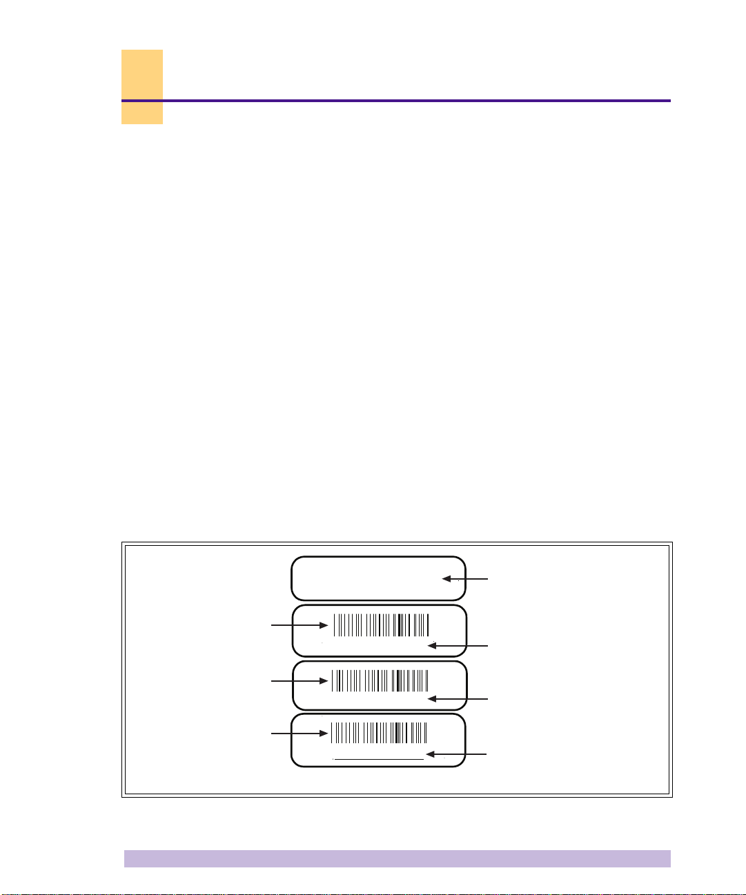
1- 1Configuration Labels
There are four configuration labels which placed on the front of each of the WAVEXpress modules as well as the chassis
to help identify the system’s current configuration. The four labels identify the part's:
• Identity
•Part number
• Revision number
• Serial number
An example of a configuration label is shown in the following figure:
T1
LH, 2 PORT, ETH
Barcode identifier of
the part number
P/N 340127
Barcode identifier of
the rev number
-200
Barcode identifier of
the serial number
S/N 00719500
Figure 1-1:
Example of the four configuration labels
Description of part
Part number
Dash or revision number
Serial number
IW352801
Unpacking the WAVEXpress/BTS 1
Release 3.3, Revision A 1/99

The TRX cards have 4 configuration labels affixed to their front face. They are:
•TRX Module 1900MHz
NOTE
☛
•PWR AMP 1900MHz
•DSP/TRX
•RF/TRX
The first two labels identify the operating frequency band of the TRX. The RF/T RX
label identifies the RF characteristics of the TRX.
Note that each descriptive label is followed by a part number, revision number
and serial number label.
1-1.1 Module Identification Numbers
The part number, revision number and serial number of each module needs to be logged. This information is needed
for technical support, warranty situations or product update s. Use the WAVEXpress/BTS Installation Checklist locate d
in the appendix to log this information.
NOTE
☛
Note only the serial number of the TRX card in the checklist. Do not note the se rial
numbers of the power amp, DSP and RF boards. This is because the serial number
of the TRX module is the only number visible from the OMC.
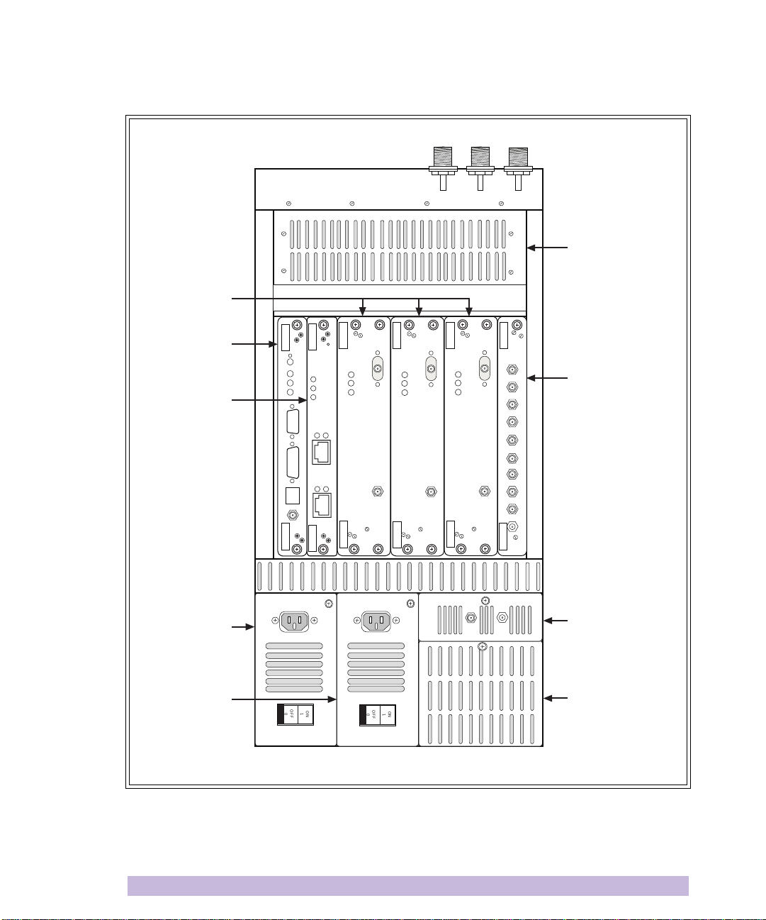
1-2 WAVEXpress/BTS Modules
The WAVEXpress is shipped with all cards and modules installed in the chassis, according to the ordered configuration.
Upon opening the front door, several basic parts to the unit are visible:
• The power supply module
• Fan assemblies
• The clock module
•Card cage
• All installed cabling.
2 WAVEXpress/BTS Installation and Commissioning Guide
Release 3.3, Revision A 1/99
TRX Cards
Cabinet Fan
IWP Card
T1 Card
Power Supply
module
Optional Power
Supply module
SCN
PWR
ON
LINE
FLT
CON
EXT
XREF
PWR
ON/LINE
FLT
ALARMS
12
PORT A
ALARMS
12
PORT B
PWR
ON
LINE
FLT
TX
RX
PWR
ON
LINE
FLT
TX
RX
TX
PWR
ON
TX
LINE
FLT
RX
RX
RX
TX
RX
TX
TEST RF DIST
-1-
RF Distribution
6.7
2,3
4,5
6,7
-3-
2,3
-2-
4,5
CLK
Card
Clock module
OFF
ON
1
0
OFF
ON
1
0
Power Supply Fan
IW346801
Figure 1-2:
A WA VEXpress/B TS (front view , door open, no cabling, maximum configuration - loaded with
1 IWP, 1 T1, 1 RF Distribution Card and 3 TRX cards)
Unpacking the WAVEXpress/BTS 3
Release 3.3, Revision A 1/99
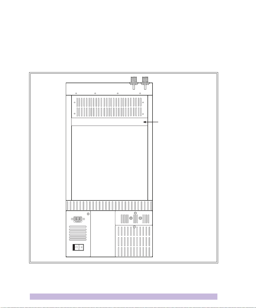
The chassis of the WAVEXpress/BTS can accept up to 9 cards. Card slots are labeled from left to right, starting at 0.
The IWP card must always be placed in slot 0 whil e the RF Dist card must alw ays be placed in slot 8. It is usual to p lace
the T1 card in slot 1, and the TRX cards, ea ch oc cu pying 2 slots, in slots numbered 2-7. The left side of the TRX card
must be placed in an even-numbered slot; ei ther in s lots numbered 2,4 or 6. TR X cards are placed from right to left . If
the BTS is a 1 TRX BTS, the TRX is placed in slot 6-7. A second TRX is placed in slot 4-5 and a third TRX is placed in
slot 2-3.
012345678
TEST RF DIST
OFF
ON
1
0
Slot
Numbers
Figure 1-3:
WAVE Xpr ess chassis (front view, door open containing one power supply and one clock
module)
4 WAVEXpress/BTS Installation and Commissioning Guide
Release 3.3, Revision A 1/99
IW265802
1-3 Modules, Connections and Indicators
The following section describes all the BTS modules, their connectors and indicator lights.
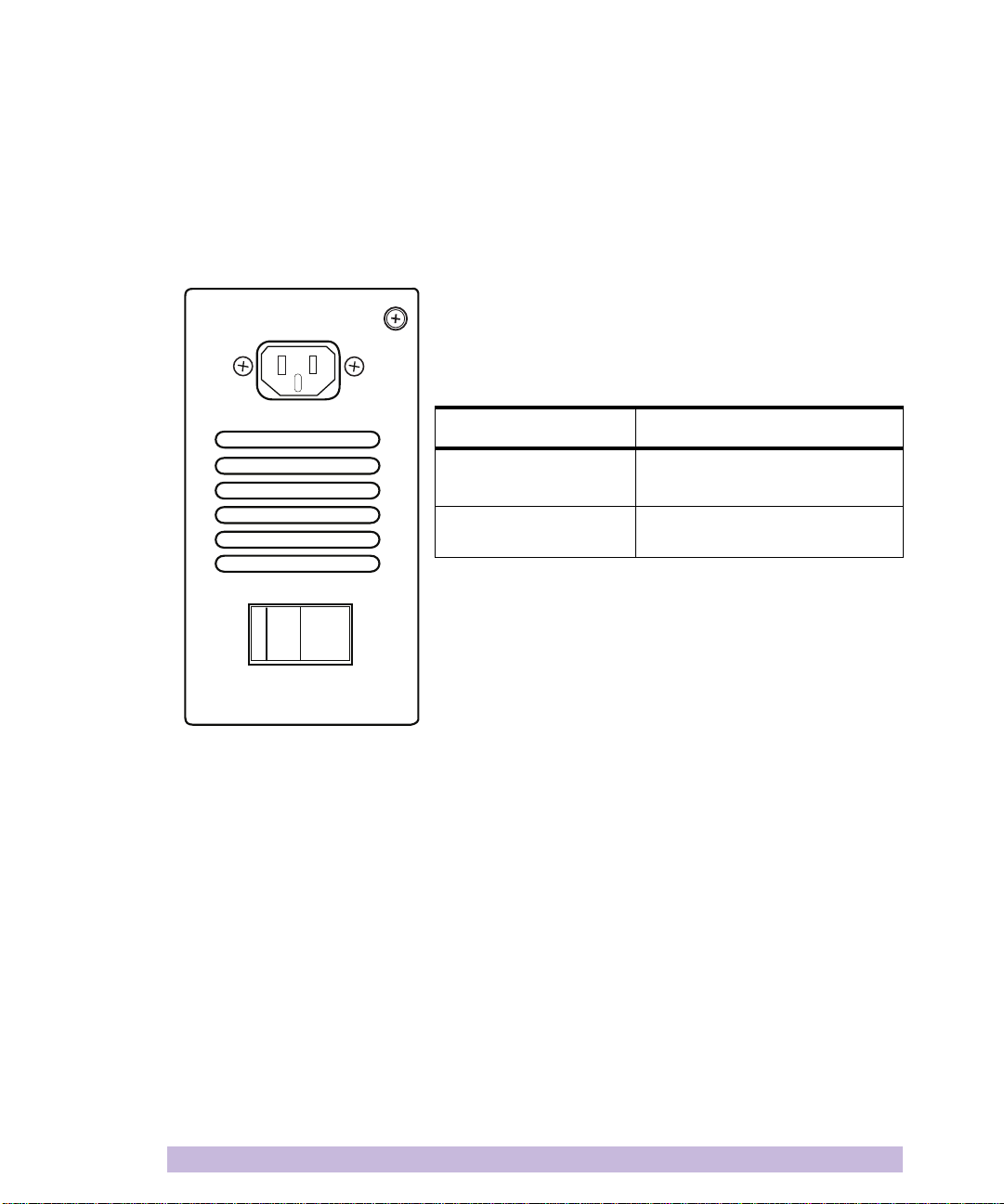
1-3.1 AC Power Supply Module
The following table describes the func tion of the conne ctors and indi cators
on a WAVEXpress/BTS AC power supply module.
Table 1-1:
Connector or Indicator Function
ON/OFF switch
Power connector
ON
OFF
1
0
IW352803
AC power supply module’s connectors and indicators
Turns power on or off to the unit
Circuit breaker for the unit.
A standard IEC 110/220V 50/60Hz
AC power cord for AC operation
Unpacking the WAVEXpress/BTS 5
Release 3.3, Revision A 1/99
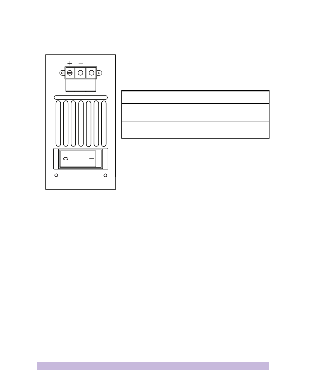
1-3.2 DC Power Supply Module
48VDC IN
GND
IW352804
The following table describes t he function of t he connectors an d indicators
on a WAVEXpress/BTS DC power supply m odule.
Table 1-2:
Connector or Indicator Function
ON/OFF switch
Power connector
DC power supply module’s connectors and indicators
Turns power on or off to the unit
Circuit breaker for the unit.
A screw clamping type barrier
terminal for DC operation
6 WAVEXpress/BTS Installation and Commissioning Guide
Release 3.3, Revision A 1/99
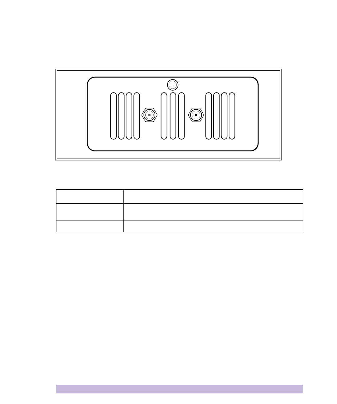
1-3.3 Clock Module
The following table describes the function of the connectors and indicators on a WAVEXpress/BTS clock module.
TEST
13 MHz
Figure 1-4:
Table 1-3:
Connector or Indicator Function
RF Dist
TEST SMA connector, allowing access to the 13MHz signal for test purposes
Front view of the clock module
Clock module’s connectors and indicators
Connects the internal clock via a semi-rigid coaxial cable to the CLK port on
the RF Dist card
RF DIST
Unpacking the WAVEXpress/BTS 7
Release 3.3, Revision A 1/99
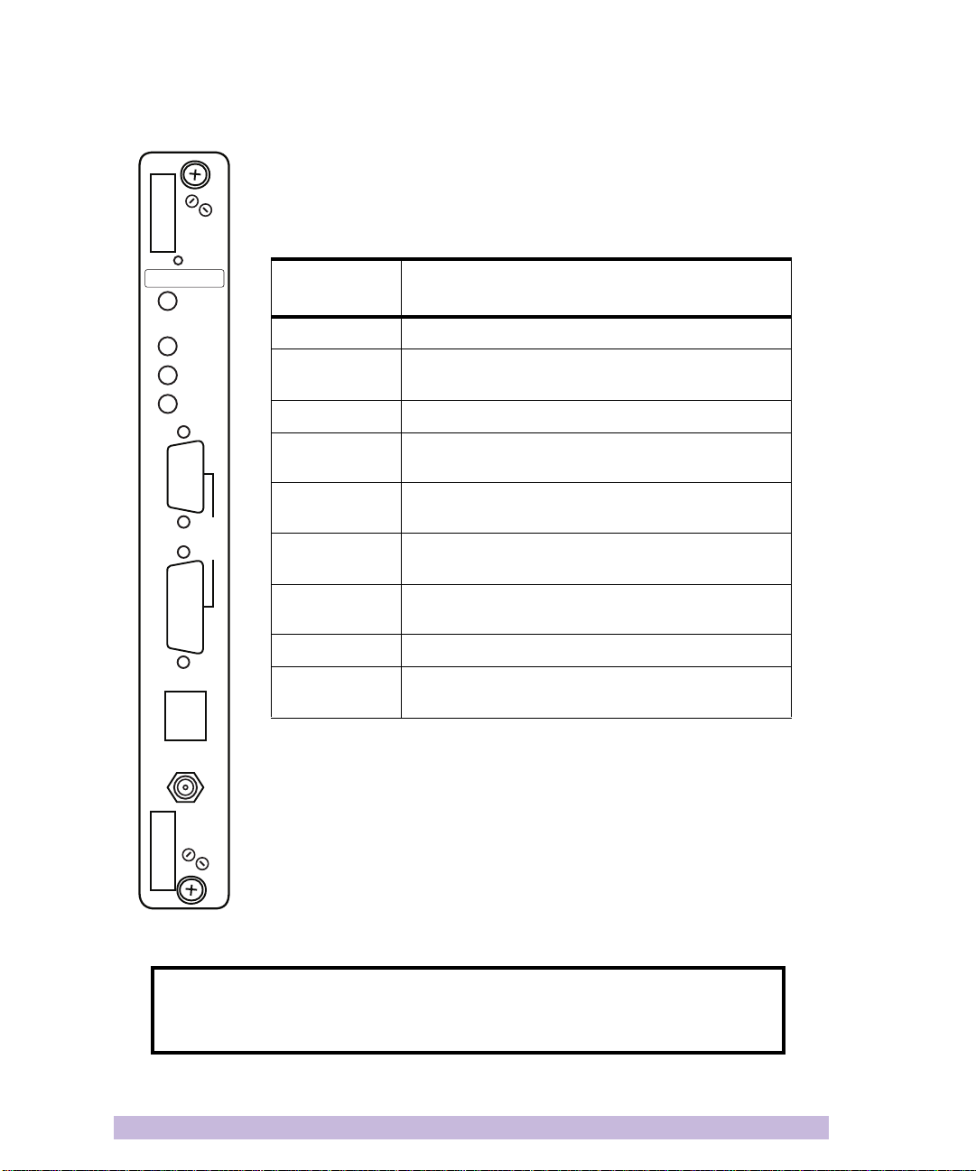
1-3.4 interWAVE Processor (IWP) Card
The following table describes the function of the connectors and indicators on a
WAVEXpress/BTS IWP card. Refer to the illustration on the left for the position of connectors
and indicators.
RST
IWP, 16MEG, MMU
SCN
PWR
ON
LINE
FLT
CDN
ENET
EXT
Table 1-4:
Connector or
Indicator
RST Th is button resets the card.
SCN When lit, the system controller LED indicates the IWP is
PWR Green LED, lit when card has power supplied.
ONLINE Green LED, lit when card is on-line, downloaded, and
FLT Red LED, lit when the card detects a fault or the c ard has
CON 9-pin, RS232 connector for serial connection to the Craft
ENET 15-pin, DB-15 connector for Ethernet connection to the
EXT RJ45 for external alarm connection.
XREF SMA connector for input from external clock for system
WAVEXpress/BTS IWP card’s connectors and indicators
Function
operational.
card boot process has been performed successfully.
not downloaded successfully.
PC.
Craft PC.
synchronization.
XREF
IW352802
NOTE
☛
A BTS 16Mb IWP card has the part number 340123. This part numbers is visi ble
on the front face of the IWP card.
8 WAVEXpress/BTS Installation and Commissioning Guide
Release 3.3, Revision A 1/99
 Loading...