

Page 1
Installation manual
Résidencia 2
1/ Presentation of the central
Unit
2/ Presentation of radio
components
3/ Recommendations
4/ Installation and
commissioning procedure
5/ Programming in the factory
Issue 3 - December 2003
Page 2

Table of Contents
1. Presentation of Alarm Unit p 3
Equipment
Wireless Components
Programming on the Installer overlay
Event Log
Remote Viewing
Technical Data
2. Presentation of Wireless Components p 4
3. Recommendations p 10
3.1 Recommendations before Starting Installation
3.2 Recommendations Relative to Alarm Unit and
Wireless Component Installation
3.3 Safety Recommendations
4. Installation and Commissioni ng Procedure p 14
5. Servicing
p 27
Appendix: Factory Setting Chart p 28
This equipment is compatible with the networks in the following countries: Germany, Austria, Belgium,
Denmark, Spain, Finland, France, Greece, Ireland, Iceland, Italy, Luxembourg, Norway, Holland, Portugal, the
United Kingdom, Sweden and Switzerland.
Nevertheless, there may problems of interoperation with the following networks: Greece, Portugal,
Switzerland.
Greece, Portugal: Pulse dialling is not supported in the basic version. It may nevertheless be added as an
option. Please contact the manufacturer’s after-sales department.
Switzerland: We recommend adding a filter for metering pulses (12 KHz) between the unit and the network
connection.)
In the event of a problem, please contact your dealer first.
▲ The equipment is guaranteed for 2 years
against faulty manufacture or raw material
defects.
▲ This Warranty shall not apply if the user has
not complied with the recommendations given,
if the unit has been put into service at a voltage
other than that shown on the rating plate or if
the unit has been connected to the wrong type of
Declaration of network compatibility:
Warranty
telephone line or, if the user has caused faults due
to negligence or by inexperience.
This manual should not be thrown away but
should be retained throughout the life of the
product.
page 2 – issue 3 - December 2003
Page 3
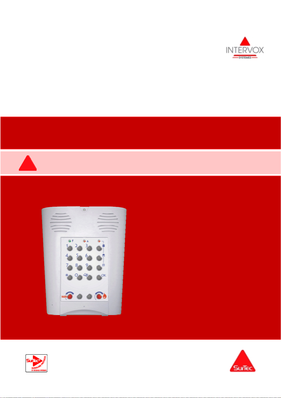
1/ Presentation of Alarm Unit
The unit combines the functions of an Alarm Unit and Telephone Modem.
Equipment
The alarm unit is equipped with:
A keypad including three LEDs and set
of keys for controlling the system
An analog telephone modem
connected to the fixed telephone
network (Z interface)
a built-in 100 dB siren with four
operating modes programmed in the
factory for each function or detector:
• Alarm transmitted without siren
• Alarm transmitted, then siren
activated
• Siren activated if transmission is
unsuccessful or if the telephone
line is cut
• Simultaneous transmission and
siren.
A radio receiver for communication
with the wireless components: motion
detectors, door and window detectors,
remote controls and keypads for
arming the system, etc.
An alarm unit tamper protection
loop monitoring the alarm unit door
and wall tamper switches
An integrated intercom module for
carrying out audio and intercom
confirmation (use depending on
country)
A memory containing the log of the
last 500 events. The log can be
viewed locally on the installer’s laptop
or remotely by upload.
A Chime module. When a door or
window switch or motion detector is
triggered, the alarm unit outputs a
chime type audio signal. Radio
channels 1 and 12 are preset to this
mode.
Wireless Components
The alarm unit manages 32 wireless channels:
22 channels are allocated to the detectors, 5 to
the remote controls or keypads and 5 are used
for the SOS function.
The wireless components are stored by teachin. Each wireless component has a unique
factory-set code out of 16 million possible
combinations.
Battery level: Each detector monitors its built-
in battery and informs the alarm unit if the
battery is low.
Supervision: Once every hour, each detector
sends a test message to the alarm unit.
The alarm unit triggers an alert when it
receives a battery low message or the detector
has not sent a test message for four hours.
This alert may generate a call to the Remote
Supervisor identifying the origin of the alert and
may also activate the siren.
Programming Using the Installer
Overlay
The installer overlay of the alarm unit allows
simplified programming without requiring a
programming tool.
In this case, the installer carries out installation
based on the default factory settings (see
appendix), then completes or changes the
settings using the installer overlay.
The installer overlay provides the following
functions:
Store wireless components, detectors,
remote controls, keypads
Program the customer’s subscriber
number
Program the call center numbers
Set the time delays on entry and exit
Set the time of the alarm unit. Setting
the time allows the event log to be time
stamped and cyclic tests to be run.
Part number : 10D3008
page 3 – issue 3 - December 2003
Page 4

Programming from a PC Using
the Configurator
Programming from a laptop requires the use of
the configuration pack.
This pack includes a special connecting cable
and the configurator program used to modify
and customize the alarm unit and transmission
protocol parameters.
Event Log
This log contains the last 500 events. For each
event, the alarm unit stores:
• The date and time of occurrence
• Alarm unit arming and disarming and code
used
• Alarm events: Triggering of a detector or
tamper switch, detector battery level
• Calling sequence to be executed
• Completion or not of the calling sequence.
The log can be viewed locally on the installer’s
laptop or remotely by the remote setting
function.
Remote Setting
The remote parameter setting function is used
to view and set the alarm unit parameters, i.e.:
• Viewing and setting of the alarm unit and
transmitter parameters
• Viewing of the events stored.
• Setting of the alarm unit time
• Reconfiguring of an alarm unit (restoring of
the factory setting)
• Updating of the software version.
Remote setting is activated from the front
panel of the alarm unit.
Technical Data
The alarm unit performs a self-test when
controlling and transmitting a line power failure
and return, the battery level and by cyclically
sending status messages (cycle in hours or
days).
The time at which the test is run can be
programmed from a PC or is delayed 12 hours
after setting the time.
Specifications
Unit dimensions (WxHxD): 188 x 230 x 68
mm
Weight: 850 grams
Material: ABS VO case
Location of use: Indoors away from
humidity
Temperature range: 0°C to 40°C
Door tamper switch
Protection class IP30 (NF standard = NF
EN 60529) IK07 (NF EN 50102).
Protection against electric shocks: Class 2
(NF standard = EN 60950)
Frequency: 433 MHz - UHF receiver.
Power Supply
Primary: Line power 230 VAC + 10%,
50 Hz, 3.2 VA
Backup by 600 mA NIMH storage battery or
equivalent.
Battery monitoring: Message sent if battery
level falls below 4.3 volts.
Line power supervision: Message sent after
a line power failure lasting 1 continuous
hour (detection limit = 100 VAC)
Alarm unit operating time: 24 hours.
2/ Presentation of Wireless Components
General
During a radio transmission, each peripheral device sends several outputs:
Alarm contact state
State of the device tamper switch
State of the device battery
In addition, once every hour, a message indicates that the device is operating correctly.
page 4 – issue 3 - December 2003
Page 5
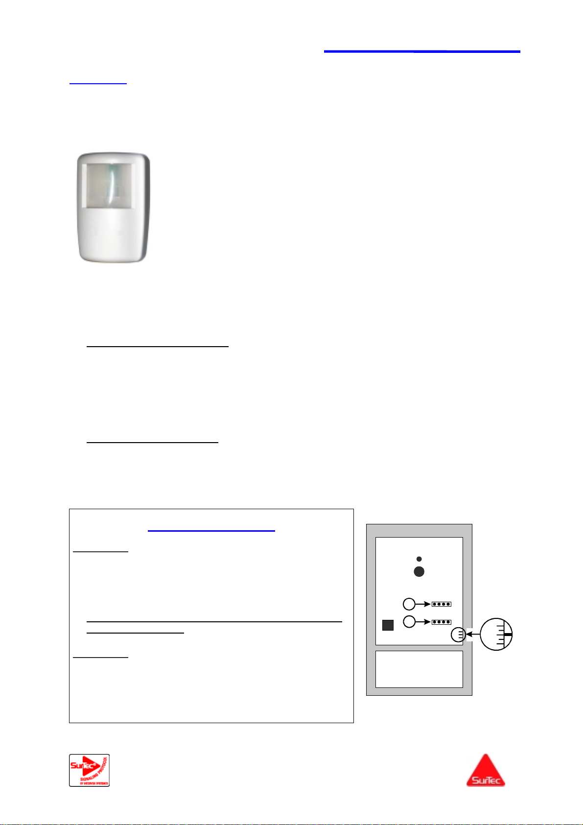
1/ Infrared movement detectors
Series 1:
A/ Standard infrared 10D9310
B/ Animal infrared 10D9320: The "Animal" detector is used for the surveillance
of premises whilst ignoring an animal of less than 18 Kg and less than 50 cm.
Operating temperature:-10° C to 50° C.
Weight: 120 g; Colour: white.
Power supply by 4 batteries - 1.5 V – AAA; life: 50 transmissions per day = 3 years;
transmission of low battery signal.
Stabilisation time (15 seconds to 2 minutes) after the installation of the
batteries. During the stabilisation time, the indicator flickers quickly.
Impulse counter to avoid unwanted triggers (1 / 3 / 5 pulses).
Dimensions: 102h X 65L X 45P mm.
In the "normal" position, the detector is tripped if it remains for 2 minutes
with no detection ;
The "test" mode is started automatically whenever the self-protection is closed
and used to perform 10 triggers over a period of not more than 30 minutes, with
immediate acknowledgement. The « test » mode is closed automatically.
When the detector is saved, the unit saves the characteristics of the detector and its serial number.
This serial number may be consulted by remote parameterisation.
Standard infrared 10D9310 :
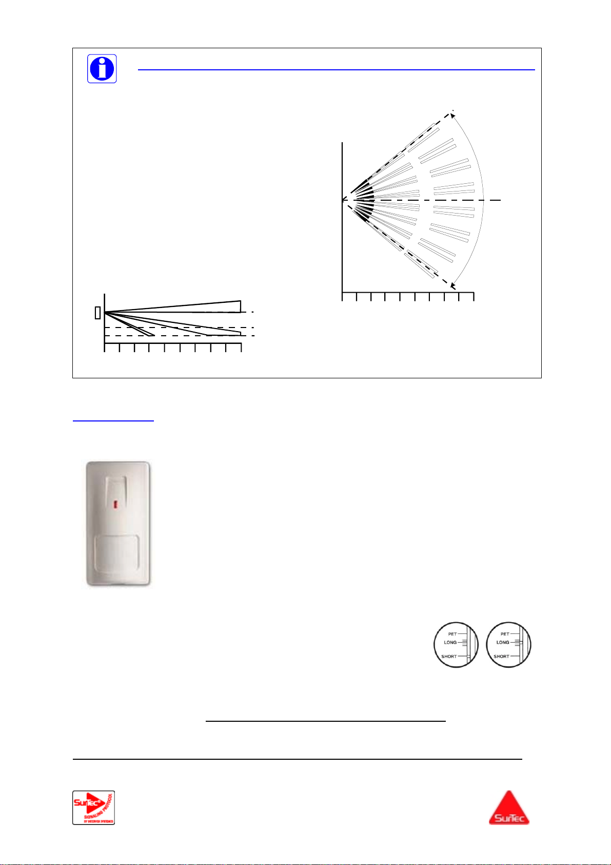
Field of vision: 90°; cover: 9 m X 9 m.
Installation of the detector at a 1,80 2,1 or 2,4 m height and adjustment of the PC board
position.
Installation at 1,8m = the PC board is set to +2
Installation at 2,1m = the PC board is set to 0
Installation at 2,4m = the PC board is set to -2
Animal infrared 10D9320 :
Field of vision: 76°; cover: 9 m X 9 m.
Installation between 2 and 2,1m and and adjustment of the PC board on -2.
Position of the jumper
Cavalier 1 :
Rst :
position of the detector in learning mode
Led
ON :
normal mode with indicator lamp lit
OFF :
normal position with indicator lamp out
Note: on completion of the installation, the jumper
should be set to OFF
Cavalier 2 :
Position 1 :
Position 3 :
Position 5 :
Instantaneous detection
Excellent protection against unwanted
trips
Maximum protection against unwanted
trips
page 5 – issue 3 - December 2003
tamper
Autoprotection
5 3 1
2
RST ON OFF
1
4 piles 1,5 V - AAA
+2
0
-2
+2
0
-2
Page 6
Recommendations concerning the installation of "animal" detectors
We advise you to set the jumper of the pulse
counter to position 5, which corresponds to a
maximum protection against unwanted trips.
According to place and installation conditions,
the jumper can be set to position 3 (good
immunity) or to position 1 (instantaneous
detection).
The detector has to be installed at a height
between 2m and 2,1m and the PC board has to
be set to position –2.
The detector has to be mounted flat against
the wall and not inclined. Do not use any balljoint or socket.
76°
2 m
1 m
0123456789(m)
0,5 m
0123456789(m)
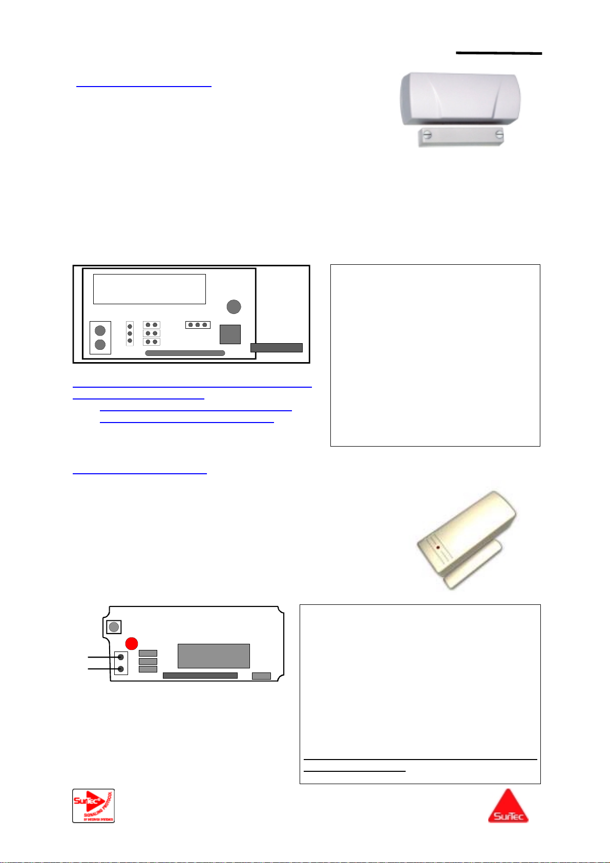
B/ Series 2: Standard infrared 10D3002
Setting the detector to "long range" or " short " :
"LONG" position: detection 6 to 16 metres
"SHORT" position: detection 3 to 6 metres
The setting is made after loosening the circuit locking screw.
Passage test: Set the jumper to "FULL SIGN",
Note: The position "FAST MON "is used for supervision for 12 minutes instead of 65 minutes.
To prolong battery life, the LED jumper should be removed on completion of the installation.
Operating temperature : 0° C to 55° C,
Weight : 100 g ; Colour : white,
Power supply by Lithium battery 3 V model CR 123A,
Life of the battery = 3 years in mode "Normal ",
Field of vision: 90°; cover: 3 to 16 metres,
Impulse counter to avoid unwanted triggers (1 / 2 / 3 pulses),
In the "normal" position, tripped 2.5 minutes after the last detection; in the
"passage test" position tripped after each passage,
Dimensions : 127.6 h X 64.2 L X 40,9 P mm,
Indicator lamp flashing: battery low.
Position the "Led" jumper,
Reinstall the front panel and carry out the passage tests,
At the end of the test set the jumper to "Normal ".
page 6 – issue 3 - December 2003
Page 7
2/ Opening detectors or technical transmitters
A/ Series 1: 10D9330
Operating temperature: 0° C to 50° C.
Weight: 50 g with battery - Magnet: 15 g; Colour: white.
Power supply by Lithium 3 V – CR123A battery; life:
50 transmissions per day = 3 years; transmission of low
battery signal.
Dimensions: 85h X 34L X 27 mm.
The contact has a terminal strip designed to be fitted with a wire loop (contact dry), in addition,
which is connected in series with the ILS contact (maximum length of the cable : 5 meters,
maximum impedance of the loop : 47 kOhms)
During memorisation of the detector, the unit saves the characteristics of the detector and its serial
number. This serial number may be consulted by remote parameterisation.
In order to compensate height differences between the detector and the magnet, you have the
possibility to put, on the detector or on the magnet, 4-cm especially designed wedges (30 special
wedges, reference 90D9330)
-
NC
J5
NO
J3
J2
J4
+
OFF ON
LED
J1
On completion of the installation, to prolong the
life of the detector battery :
the jumpers J1 should be OFF position,
the jumpers J2 should be removed .
B/ Series 2: 10D3003
J1 :
ON : indicator lamp lit
OFF : indicator lamp off
J2 :
ON : transmission with each opening
OFF: tripped if the detector does not
detect for 2 minutes.
J3 :
Always in the OFF position
J4 :
ON: bimetal strip used (magnet)
OFF: bimetal strip not used (use in
technical transmitter).
J5 :
NC: connection of a normally closed
loop
NO: connection of a normally open
loop
Operating temperature : 0° C to 50° C
Weight : 75 g with battery -; Colour : white,
Power supply by Lithium 3 V model CR 123A battery; life =
3 years in normal mode : "HOLD ON "
Dimensions : 35 h X 81 L X 33 P mm
Transmission on alarm and end of alarm.
The contact has a terminal strip designed to be fitted with
an additional wire loop.
Indicator lamp: When the battery is low, the indicator lamp
flashes 3 times on each transmission.
J2: in "FAST" position: connection of impact
contacts,
J2: in "SLOW" position: connection of magnetic
contacts.
J3 : in "NO" position: connection of the external
sensor in NO (input E)
J3: in "NC" position: connection of the external
sensor in NC (input E)
J4: in "OFF" position: use of the bimetal strip with
the magnet,
J4: in "ON" position: bimetal strip not used.
At the end of the test, jumper 1 should be in the
"HOLD ON" position.
E
+
J1
J2
J3
-
J4
Programming of the 4 jumpers:
J1: in the "HOLD ON" position: the alarm is
tripped 2.5 minutes after the last detection
and the end of alarm is transmitted
immediately,
J1 in the "HOLD OFF" position: the alarm is
tripped immediately.
page 7 – issue 3 - December 2003
Page 8

3/ Remote controls, call SOS and Rounds
A/ Series 1
2 On/Off keys: 10D9230
4 On/Partial On/Off/ SOS keys: 10D9250
1 SOS key: 10D9220
1 Round key: 10D9210
During memorisation of the remote controls, the unit saves their characteristics and serial numbers.
This serial number may be consulted by remote parameterisation.
Operating temperature: 0° C to 50° C.
Weight: 50g, Colour: dark grey.
Dimensions: 60h X 40L X 11P mm.
Frequency: 433.92 Mhz.
Power supply by a CR2032 battery
Life : 10 transmissions per day = 3 years,
Low battery: an alarm is transmitted to the unit
and the indicator lamp flashes.
B/ Series 2
2 On/Off keys : 10Z9230
4 On/Partial On/Off/ SOS keys : 10Z9250
1 Round key: 10Z9210
Violet key:
Green key:
Grey key:
Red key:
Operating temperature: 0° C to 50° C.
Weight: 50g, Colour: dark brown.
Dimensions: 104h X 44L X 24P mm.
Frequency: 433.92 Mhz.
Power supply by Lithium 3.6 V - 1.2 Ah battery;
life: 50 transmissions per day = 3 years;
transmission of low battery signal.
C/ Series 3:
2 On/Off keys / SOS: 10D3005
Red key: Total surveillance,
Green key: Off : hors surveillance,
Pressing both keys at the same time: SOS, duress
call.
Operating temperature : 0° C to 50° C
Colour : black
Power supply by Lithium battery.
Battery model CR2032; 3 Volts.
Life : battery life 3 years
Dimensions : 70 h X 35 L X 12 P mm
Total surveillance
Total off and memorisation of
the remote control during
installation
Surveillance of zone 1
SOS
page 8 – issue 3 - December 2003
Page 9
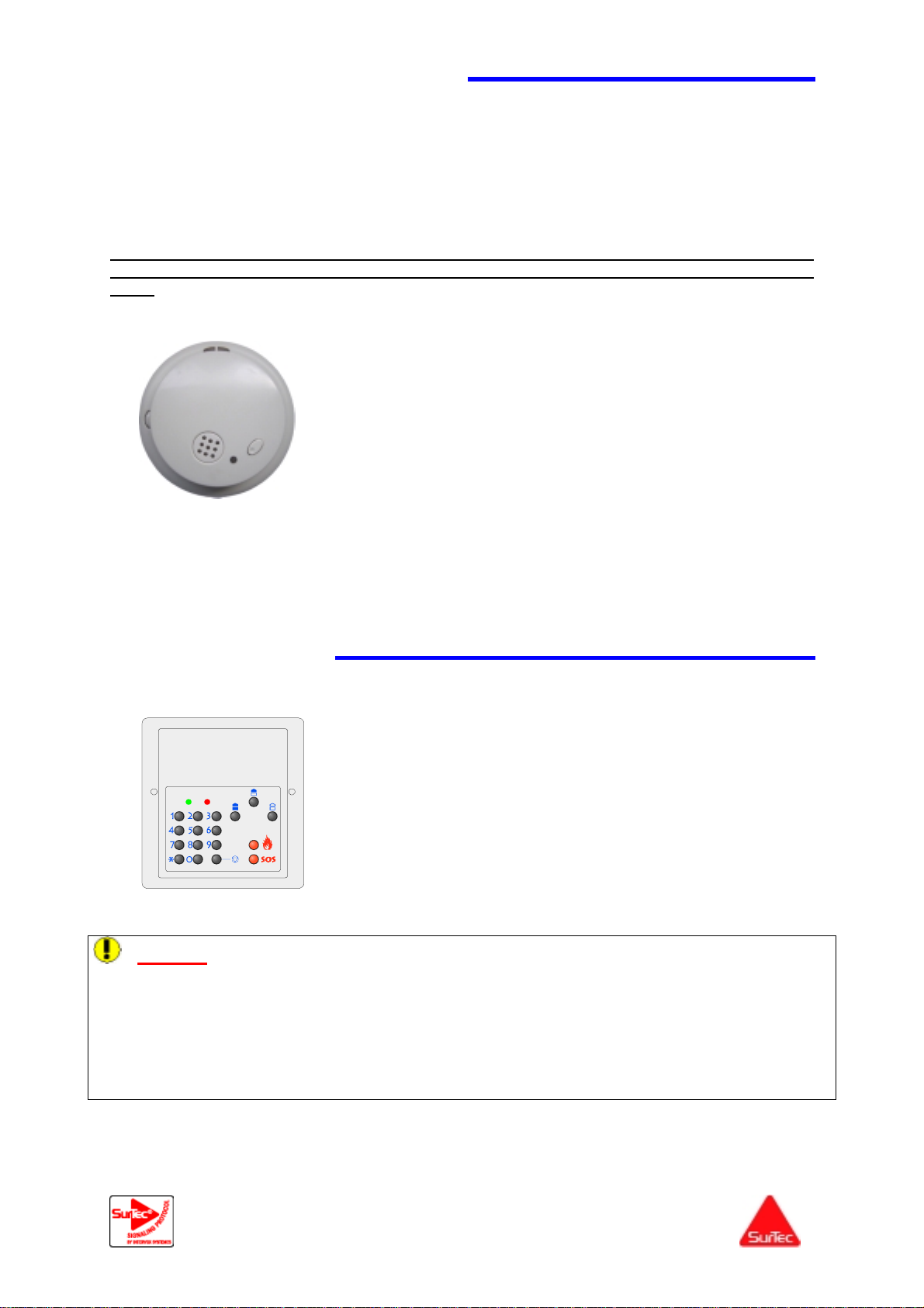
4/ Smoke Detector 10D9350
Wireless smoke detector P/N 10D9350 is designed to be installed inside the protected premises. It
must be installed on the ceiling in the center of the room.
When smoke is detected, the system generates a series of three audio signals and triggers a radio
transmission to the alarm unit. The series of audio signals is repeated every three seconds until smoke
is no longer detected.
The smoke detector includes two parts: the smoke detector head and the base unit containing the
radio transmitter.
The radio transmitter continuously monitors its power supply level. When it detects a low
power supply level, it sends a special message to the alarm unit and it generates an audio
signal
▲ Dimensions: diameter 142 mm; height 45 mm
▲ Radio link frequency: 433.92 MHz
▲ Power supply:
Detector head: one 9V alkaline battery
Radio transmitter: three 1.5V alkaline batteries type
AAA with battery low detection when the voltage
drops to 3.15V.
▲ Detector head operating time: three years with a triggering test
performed once a month
▲ Radio transmitter operating time: three years with use of ULTRA
alkaline batteries
▲ Operating temperature range: -0°C to +50°C
▲ Use: Indoors away from humidity
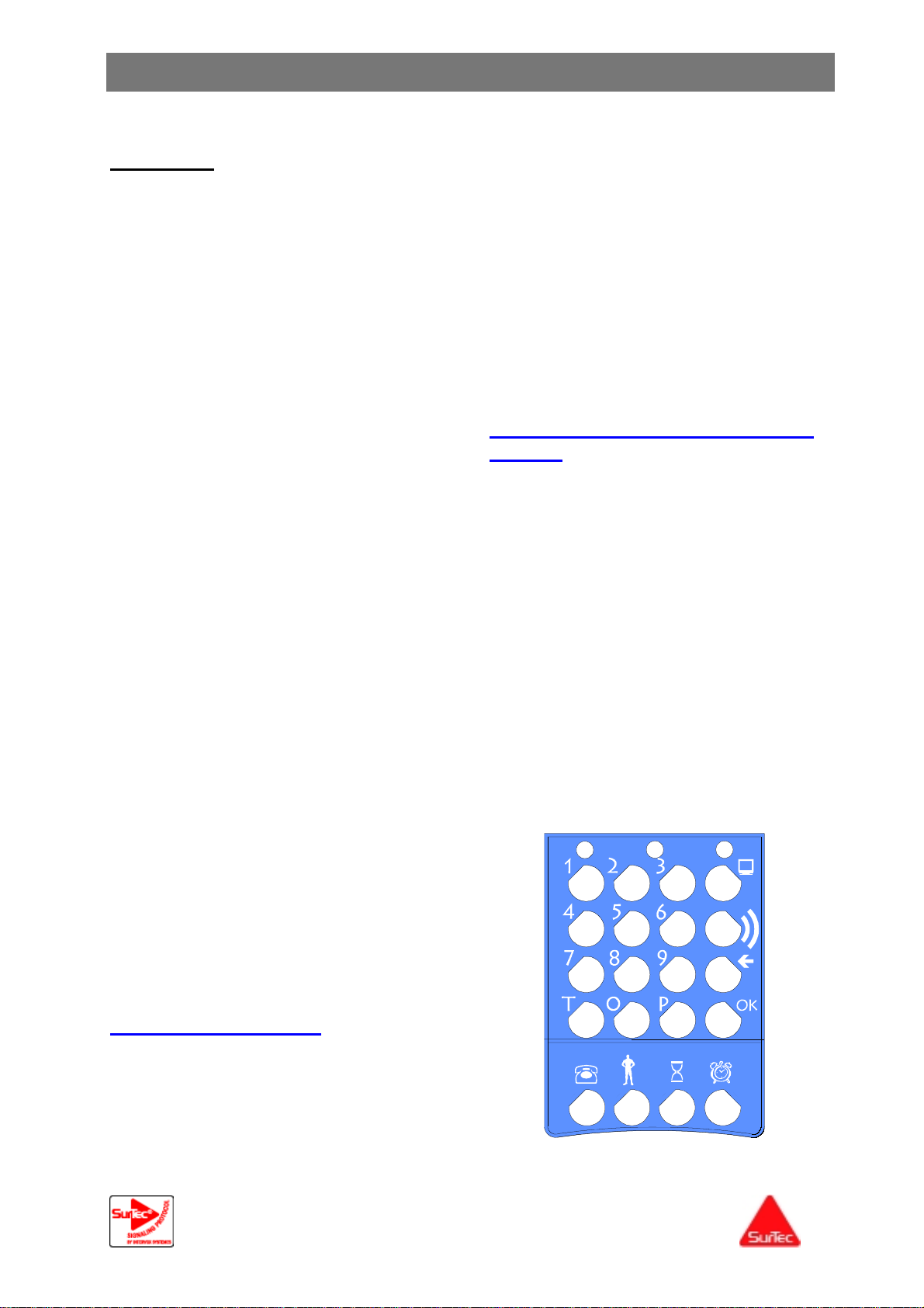
Wireless Keypad
5/
Caution: The alarm unit devices such as keypad, remote control, break-in detectors, etc. are
generally equipped with lithium batteries, giving them a very long operating time.
If these batteries remain in storage for one or two months, they may enter a passivation phase.
Lithium batteries contain liquids which solidify on the terminals during an extended storage period. If
this happens, even if the voltage measured across the terminals is correct, no current can flow
through the battery.
To make the battery operational again, connect a 30-ohm resistor across the terminals until the
voltage (current?) returns to nominal level.
Specifications
Operating temperature range: 0°C to 55°C
Power supply by one 3.6 V, 1 Ah lithium thionyl chloride battery
Battery model SAFT LS 14250 (L = 24.8 mm / dia 14.4 mm)
Operating time: 2 years
Frequency: 433.92 MHz
Dimensions (LxWxH): 120 x 114 x 32 mm
The wireless keypad is used to activate total supervision or partial
supervision, deactivate supervision, make SOS or fire alarm calls
and read the alarm unit status.
page 9 – issue 3 - December 2003
Page 10

Recommendations
You are about to install and put into service an alarm unit. We suggest you comply
with the following recommendations:
1. Read this manual carefully and, in particular, the chapter concerning
the installation recommendations.
2. Follow the instructions set out in the installation procedure to the
letter.
3. Find the best location for your unit, in accordance with its installation
conditions.
4. Before connecting the telephone line, check the installation with your
customer and whether he has an answering machine, fax or Internet
connection (see connection chapter).
5. Unpack and prepare the various radio peripherals but do not install them
(intrusion detectors, keypads, etc.). We recommend programming them
close to the unit and securing them only after checking their radio range
from the location required.
6. Programme the various radio peripherals (self-learning).
7. From the required location of each radio peripheral, check, their radio link
with the unit, in "test" mode.
8. Once their final location has been determined and their range checked,
install and secure the radio peripherals.
Some useful tips before starting the installation
9. Test the installation in full.
page 10 – issue 3 - December 2003
Page 11

Environment and location of the unit
The unit is a wireless alarm system which communicates with its peripherals using
radio transmissions.
The propagation of radio frequencies differs depending on the place of installation,
location and height of components, and on the construction materials found.
The position of the unit on the site to be protected is therefore strategic. This
position should take into account the following table and indications:
Materials found Radio frequency penetration rate
Wood and plaster 90 to 100 % of radio transmissions
Brick 75 to 90 % of radio transmissions
Reinforced concrete 0 to 50 % of radio transmissions
Metal structures 0 to 10 % of radio transmissions
Since the ground in an obstacle to the propagation of transmissions, system
components should not be installed at ground level,
No component should be installed on a metal partition or structure.
In all cases, we recommend installing the unit in the centre of the premises to be
protected, at an average height of 1.50 metres, whilst taking into account the location
of the telephone line and incoming feeder of the 230 volt mains power supply.
Environment and location of peripherals
The peripherals should not be installed before being programmed.
Once programmed, their final location shall only be chosen and confirmed after
checking radio ranges and interference from this location.
Opening detectors:
If an opening detector has to be installed on a metal door or frame, the installer should
insert an insulating shim between the opening detector and the metal part so that the
action of the magnet on the opening contact is not disrupted by the metal mass and
that this metal mass does not interfere with radio transmissions.
Movement detectors:
Useful hints for installing units and radio components
Movement detectors are infrared detectors. They are therefore sensitive to changes in
temperature and should not be installed close to a source of heat (convector,
chimney), in a draft or in direct sunlight.
To avoid saturation of radio transmissions, the peripherals should not be
installed in the direct vicinity of the unit, or at a distance of less than 3 metres.
page 11 – issue 3 - December 2003
Page 12

The installation, upkeep and maintenance of this equipment may
only be carried out qualified, authorised personn e l .
Installation conditions, environment
▲ Wherever possible, the unit and keypads should not be installed in a room with a
static floor covering (carpet, etc.), close to high power distribution cubicles, switches
generating high over voltages and in the immediate vicinity of a source of heat
(radiator, electric convector heater, etc.).
▲ Provide, around the unit casing, sufficient clearance for good ventilation through the
openings provided.
▲ The equipment is designed to operate at an ambient temperature of between 0° C
and 40° C.
▲ The equipment should not be installed in a location where it may be sprayed with
water.
Protection of the Installer and Repair technician
▲ To ensure safe conditions during installation and maintenance operations, an
easily accessible
230 Volt disconnection switch must be installed uplink of the unit.
This device should disconnect both poles at the same time and the distance between
the contacts should be at least 3 mm.
The installation should include a differential protection device
Any work on the system should be carried out only after opening the
disconnecting switch and after checking the status of the mains power supply
indicator lamp on the unit.
Protection of Users
This equipment is manufactured in accordance with international standards,
which ensure its suitability and safety.
The various cubicles and components used are self-extinguishing, in accordance
with the standards in force.
Protection against lightning
The telephone line and mains power supply of the equipment are fitted with
protection against over voltages and electrostatic discharges. This protection is also
used against the secondary effects of lightning.
Protection against direct lightning strikes cannot be provided and when the
equipment is installed in a
installed on the telephone line and the mains power supply.
zone at risk, an additional lightning arrester should be
These systems are only effective if the lightning arrester is connected to an earth
connection, in accordance with the specifications. In general, such systems should be
Safety Recommendations Safety Recommendations Safety
replaced after a lighting strike.
This type of equipment should not be installed in the terminals since any protection
becomes ineffective when lightning enters the equipment.
page 12 – issue 3 - December 2003
Page 13

Connection of the 230 Volt electrical network
▲ The equipment is designed to operate at a single phase voltage of 230 volts, 50 Hz.
Before making the electrical connection, check that the parameters of the electrical
network (voltage, power, frequency, etc.) correspond to the operating parameters
shown on product rating plate and in the manual.
▲ The equipment is designated class 2, that is it does not include an earth connection.
▲ The installation should be fixed (with no sockets).
▲ The connection of the unit to the 230 Volt distribution network should comply with
trade practises in accordance with standards NFC-15100.
Do not switch on the unit when a fault has been detected.
To avoid the risk of electrical shock:
WARNING
• Connect the mains power supply after completing the wiring,
• Cut off the mains power supply and the telephone line before starting
work,
• The "dangerous voltage" and "TRT" (telecommunication network
voltage) danger zones should only be fitted with the connections
designed for them.
Batteries
The batteries of the system peripherals are Lithium batteries. Never use standard
batteries.
All the batteries of an installation should be replaced at the same time.
The batteries should not be short-circuited, modified, removed or subject to
impact.
Spent batteries should not be discarded or burnt. They should either be deposited
in a collection centre or returned to the supplier.
Caution: Certain alarm unit peripherals, such as control keypads, portable
remote controls, intrusion detectors, etc. are fitted with Lithium batteries, which
gives them very long battery life.
If these batteries are stored for 1 to 2 months, they may go into "Passivation"
phase.
Lithium batteries contain liquid components and in the event of prolonged
storage, this liquid solidifies on the output terminals. In this case, the voltage
measured across the terminals is correct but the battery is not operational since it
does not generate any current.
To make it operation, discharge it into a 30 ohm resistor until is reaches its rated
voltage again.
Safety Recommendations Safety Recommendations Safety
Batteries
Batteries should only be replaced by models of the recommended type or the
equivalent.
Spent batteries should not be discarded or burnt. They should be deposited in a
collection centre.
page 13 – issue 3 - December 2003
Page 14

Installation and commissioning procedure
To ensure that installation is carried out under optimal conditions, it is necessary
to perform the steps below in the order given.
1/ Establish an installation plan based on the default factory programming. This plan
is used to determine:
2/ Review the telephone system and check whether it includes an answering machine
or a fax and whether the user has an Interconnect connection by modem, RNIS or
ADSL
The alarm unit must be installed in compliance with the recommendations given in the sections
Installation Recommendations and Safety Recommendations.
To open the alarm unit, remove the screw cap and unscrew and remove the attaching screw.
▲ The power cable must have a diameter of 8 mm and include two conductors with a cross-sectional
▲ You must use standard cables conforming to the IEC standard or the harmonized CENELEC
▲ The cable must be inserted through the Line inlet (1) and be clamped in the anti-pulloff clamp (2).
The unsheathed length of cable must not protrude by more than 10 mm
from the line power terminal. The stripped length of cable must not
exceed 7 mm.
Only one wire must be connected to each terminal of the line power
terminal board. If using a multiconductor cable, the stripped part must
not be tin-plated.
With the alarm unit user
1
The approximate locations of the detectors. The final detector locations are confirmed after
making radio range tests.
The alarm unit location. The alarm unit must be located in the centre of the site to be monitored.
On a site with several levels, it is recommended to place it on the median level.
If possible, avoid basement corners and install away from electric meters, television sets,
computers, microwaves, etc.
The location should be near a telephone line and 230 VAC line power and where applicable,
allow the use of a remote control unit used outside the site to be protected.
The access path to the alarm unit and therefore detectors which should be delayed and the time
delays on entry and exit to be used for each detector.
The detectors active for total supervision and partial supervision.
(the different cases of connection are described in item 5: Connecting the telephone line).
2
Opening, positioning and attaching the alarm unit
3
Connecting 230 VAC line power
area above 0.75 mm
standards.
The line power wires are connected to terminal (2).
2
(maximum 2.5 mm2).
10 mm
7 mm
page 14 – issue 3 - December 2003
Page 15

1 Inlet for 230 VAC connection
2 230 VAC line power terminals
3 Inlet for the telephone line
4 Terminals for analog fixed telephone
line and system telephone sets
5 The ribbon cable interconnecting the
front panel card and main card is installed in
the unit supplied. If it comes loose, be careful
not to reverse the terminals when
reconnecting it.
6 Jumper used for factory testing. This
jumper must remain in place.
7 Connector used for factory testing: do
not connect anything to this connector.
8 Laptop connector for setting up the
alarm unit. The laptop is connected using
the configuration pack.
9 Connector for backup battery pack.
10 Door tamper switch
10
Hasardous
voltage
9
2
8
7
5
6
3
L1/L2
4
P1/P2
zone TRT
1
4
Connecting the telephone line
℡℡℡℡ The cable must be inserted through the Telephone line inlet (3) and be clamped in the anti-pulloff
clamp.
℡℡℡℡ The unit is connected to an analog fixed line or a TRT3 type connection (TRT3: System whose nominal
operating voltages exceed 42.4 V peak or 60 V continuous and on which voltage spikes from the telecom network are possible;
conventional analog system, Z interface).
℡℡℡℡ The terminal must be connected as shown below:
1/ Standard system with one or more telephone sets
L1/L2 P1/P2
BEFORE : AFTER :
Telephone
line
feeder
page 15 – issue 3 - December 2003
℡
1
3
℡
1
1
3
3
℡
1
3
Telephone
line
feeder
℡
1
3
℡
1
1
3
3
℡
1
3
Page 16

2/ ISDN system with one or more telephone sets and an Internet link
L1/L2 P1/P2
Telephone
line
feeder
ISDN
coupler
unit
ISDN
Interface
℡ ℡ ℡
PC
3/ System with one or more telephone sets and an Internet link by ADSL
L1/L2 P1/P2
Telep hone
line
feeder
Imput
coupler
ADSL
modem
Restricted line: Make sure your customer does not have a restricted line and does not
activate a restricted line by a code when leaving the premises.
℡ ℡ ℡
PC
The equipment cannot be connected directly to an ISDN line.
Connect the 230 VAC input to the line power isolating switch:
Install the battery pack:
Place the battery in the compartment and attach it with the tie strap supplied with the equipment.
To make your security system fully operational as rapidly as possible, the backup battery was charged
in the factory and packaged for delivery. Check that the installation date indicated on the battery has
not expired.
Connect the battery pack:
5
Power on
Before proceeding to connect the unit to 230 VAC line power, check the
line power input to make sure the parameters (voltage, power, frequency,
etc.) correspond to the operational parameters indicated on the unit
nameplate and in the guide.
Before proceeding to connect the alarm unit to 230 VAC line power, remove the
foam cushion glued to the transformer, used to hold the power supply card in
place during shipping.
The green LED flashes.
● The green LED comes on.
● The backup battery is fully operational after an additional 16-hour charge period.
page 16 – issue 3 - December 2003
Page 17

The alarm unit does not boot unless 230 VAC line power is connected and present.
The 3 LEDs on the front panel come on if the battery is connected but
line power is absent.
● Disconnect the 230 VAC via the isolating switch and make sure the green LED flashes,
confirming absence of 230 VAC.
● Reconnect line power: The green LED comes on steady.
● The alarm unit opens the Administrator menu. The red LED must be lit to indicate that the
alarm unit is in Test mode.
● To access the Installer setup menu, enter the installer code (factory setting 2222) and press
the T key. The Mode LED flashes twice per second.
installer code +
The installer overlay of the alarm unit allows simplified programming without requiring a programming
tool. This programming is based on the factory settings (see appendix for the chart of factory settings).
The installer overlay provides the following functions:
The other settings are accessible by the remote setting function or from a laptop.
6
Programming
Programming is not possible unless line power is connected and present.
Store wireless components: detectors, remote controls, keypads, etc.
Program the customer’s subscriber number
Program the call center numbers
Determine the time delays on entry and exit
Set the time of the alarm unit. Setting the time allows the event log to be time stamped and
cyclic tests to be run.
Activate remote viewing of the alarm unit status from the technical center.
Telephone numbers
A
B
Customer subscriber number
H
Time delay on entry and exit
C
Setting the time
D
Confirm
E
Delete
F
Store detectors
G
Download data
H
J
K
G
F
E
Wait for dial tone
J
K
Access the Installer menu or Pause
C DBA
A
page 17 – issue 3 - December 2003
Page 18

1. Accessing Installer Setup Mode from Off Mode
Entry in setup mode is protected by an access code. Follow the procedure below to access setup
mode:
(factory-set administrator code: 1111; factory-set installer code: 2222).
If the codes entered are correct, the alarm unit goes into Installer Setup mode. The Mode LED
flashes twice per second.
When you press , the alarm unit exits from Installer setup mode and goes into Detector test mode.
The Mode LED comes on.
2. Programming the Subscriber Number
administrator code + + installer code +
Proceed as follows to program the subscriber number:
Press key. The Mode LED flashes
Enter the subscriber number on 8 digits.
Press OK to confirm.
The Mode LED flashes twice per second.
+ 8-digit subscriber no. +
The alarm unit acknowledges data entry by generating an acceptance signal if accepted or a refusal
signal if the 8 digits or the sequence is entered incorrectly.
The alarm unit returns to Installer setup mode.
When programming the subscriber number, you can press to return to the start of Installer setup
mode.
3. Programming the Telephone Numbers
The alarm unit supports three telephone numbers (preset in the factory).
Proceed as follows to program a telephone number:
Select the number to be programmed (1, 2 or 3)
Press key ℡
Enter the telephone number on the numerical keypad. Enter T before the number to program
a wait for the dial tone or
Press OK to confirm.
The Mode LED flashes twice per second.
Example of programming sequence to set the first telephone number as 01 55 23 25 25:
℡: The Mode LED flashes
℡℡
P for a pause.
1 + + + 0155232525 +
page 18 – issue 3 - December 2003
Page 19

The alarm unit acknowledges data entry by generating an acceptance signal if accepted or a refusal
signal if the number or the sequence is entered incorrectly.
The alarm unit returns to Installer setup mode.
When programming the telephone number, you can press to return to the start of Installer setup
mode.
If the alarm unit is connected to a PABX, it is necessary to dial 0 to access the outside line.
Enter the following sequence: T 0 T 0155232525.
If the tone output by the PABX is not conformant and not recognized by the alarm unit,
replace the Ts by Ps. In this case, the alarm unit waits 4 seconds before starting to dial.
4. Setting the Time Delays on Entry and Exit for Each Detector
Proceed as follows to set the time delays on entry and exit:
Enter the detector number on 2 digits
Press key
Program the time delay on entry in seconds on three digits
Press OK to confirm.
Program the time delay on exit in seconds on three digits
Press OK to confirm.
The Mode LED flashes twice per second.
Example: For detector 2, set a time delay on entry of 30 seconds and a time delay on exit of 45
seconds.
. The Mode LED flashes
02
030 +
+ 045 +
The alarm unit acknowledges entry of each item by generating an acceptance signal if accepted or a
refusal signal if the sequence was not correctly entered, then returns to Installer setup mode..
When programming the time delays, you can press to return to the start of Installer setup mode.
5. Storing the Detectors, Remote Controls and Keypads
Each system component - detector, keypad, remote control unit, siren - has a unique factory-set code
out of several million possible combinations.
To be recognized, each component must be stored in the alarm unit. Storage is by teach-in.
Channels 1 to 22 are reserved for the detectors
Channels 23 to 27 are reserved for the remote controls or keypads
Channels 28 to 32 are reserved for the SOS functions triggered by a particular
The installer uses the factory settings to assign the detectors to the wireless channels (see appendix
for factory settings).
transmitter or remote control.
page 19 – issue 3 - December 2003
Page 20

)
The factory parameter settings can be changed to customize the system. The
new settings can be made from a PC equipped with the Configurator software and
connected to the alarm unit via the special adapter cable or by download.
Rules to be followed:
The detectors and other devices must be set on a desktop near the alarm
unit for storage before they are installed. To avoid any risk of error or
confusion between detectors or between wireless devices, it is
recommended to proceed in the following order:
▲ Do not connect any batteries to the wireless devices
▲ Enter the channel number to be stored
▲ Press key )): The Mode LED flashes
• If the channel is already programmed, the alarm LED comes on
steady
• If the channel is free, the alarm LED flashes and the alarm unit goes
on wait for reception of a radio transmission
▲ Connect the battery to the detector or device to be stored on the channel
selected
▲ Perform the teach-in procedure specific to each device (refer to Storage
Procedure in the next section)
▲ On reception of the radio transmission, the alarm unit outputs:
• A rejection audio signal (4 beeps) if the wireless device is not
recognized by the alarm unit or if it is already stored on another
channel, or
• An acceptance audio signal (long beep)
▲ Press OK to confirm device storage.
▲ The Mode LED flashes twice per second.
▲ Remove the battery from the device
▲ Repeat the procedure for each device to be stored, installing the battery in
only one device at a time.
Example for storage of a detector on channel 1:
1 +
) radio message ♫ + OK
When programming the detectors, you can press to return to the start of
Installer setup mode.
If you make a mistake during the storage procedure, it is recommended
to remove the battery and start over from the beginning
page 20 – issue 3 - December 2003
Page 21

Memorisation procedures
A/ "Infrared" detectors
Series 1: standard infrared 10D9310 and Animal infrared 10D9320
Series 2: standard infrared 10D3002
B/ Opening detectors
Series 1: opening detector 10D9330
Series 2: opening detector 10D3003
Open the detector and set the jumper 1 to the "RST" position,
Select a channel from 01 to 22,
Press key )): The Mode LED flashes
Insert the batteries in their housing respecting their polarities,
Wait for the stabilisation time (15 seconds to 2 minutes). During the stabilisation
time, the indicator flickers quickly.
Perform a detection or a self-protection operation,
Check that the alarm unit broadcasts the acceptance audio signal
Confirm the recording using the OK key,
Reset the jumper 1 to the "OFF" position,
Before closing the detector, make sure that the antenna is straight and in standing
position.
Open the detector,
Select a channel from 01 to 22,
Press key )): The Mode LED flashes
Insert the battery in its housing respecting their polarities,
Press the self-protection strip pendant 3 seconds then release,
Check that the alarm unit broadcasts the acceptance audio signal
Confirm the recording using the OK key.
Open the detector and set the jumpers according to the use of the detector (see page 10),
Select a channel from 01 to 22,
Press key )): The Mode LED flashes
Insert the batteries in their housing respecting their polarities,
Close the self-protection: the indicator lamp comes on during transmission,
Check that the alarm unit broadcasts the acceptance audio signal
Confirm the recording using the OK key.
Before closing the detector, make sure that the antenna is straight and in lying
position.
During the detector memorization :
1/ The magnet should not be used (keep the magnet away from the detector to avoid any
false trigerring)
2/ If you use the terminal strip, the jumper has to be in NC position and nothing should be
wired to this strip.
Open the detector and set the jumpers according to the use of the detector (see
page 9),
Select a channel from 01 to 22,
Press key )): The Mode LED flashes
Insert the batteries in their housing respecting their polarities,
Press the self-protection strip for 3 seconds then release.
Check that the alarm unit broadcasts the acceptance audio signal
Confirm the recording using the OK key.
page 21 – issue 3 - December 2003
Page 22

C/ SOS transmitters
Series 1: SOS transmitter 10D9220
Series 2: SOS transmitter 10Q4200 AND 10Q4210
D/ Remote controls:
Series 1:
2 On/Off keys: 10D9230
4 keys On/Off/Zone 1/SOS : 10D9250
Series 2:
2 On/Off keys: 10Z9230
4 keys On/Off/Zone 1/SOS: 10Z9250
On all models:
• Mini-switch 1 : OFF
• Mini-switch 2 : OFF
Select a channel from 28 to 32.
Press key )): The Mode LED flashes
Press the button for at least 10 seconds: the indicator lamp comes on once
after 2 seconds then comes back on 10 seconds.
Check that the alarm unit broadcasts the acceptance audio signal
Confirm the recording using the OK key.
Note : As the self-learning radio message is broadcasted only after 10 seconds,
do not take refusal signals broadcasted by the alarm unit during these 10
seconds into account.
Select a channel from 28 to 32.
Press key )): The Mode LED flashes
Press the red button: the indicator lamp comes on during transmission,
Check that the alarm unit broadcasts the acceptance audio signal
Confirm the recording using the OK key.
Select a channel from 23 to 27.
Press key )): The Mode LED flashes
Press one of the remote control keys for at least 10 seconds: the indicator
lamp comes on once then comes back on 10 seconds.
Check that the alarm unit broadcasts the acceptance audio signal
Confirm the recording using the OK key.
Note : As the self-learning radio message is broadcasted only after 10 seconds,
do not take refusal signals broadcasted by the alarm unit during these 10 seconds
into account.
Remove the screws behind the remote control,
Separate the cover from the back and remove the printed circuit board,
Select a channel from 23 to 27.
Press key )): The Mode LED flashes
Insert the battery in its housing respecting their polarities,
Press the "green"
key: the indicator lamp comes on during transmission,
Check that the alarm unit broadcasts the acceptance audio signal
Confirm the recording using the OK key.
page 22 – issue 3 - December 2003
Page 23

Series 3: 2 On/Off/SOS keys: 10D3005
The remote control should be memorised on 2 channels: the "remote control" channel for
placing under and off surveillance and the "SOS"' channel for duress calls.
Memorisation of the remote control:
Select a channel from 23 to 27.
Press key )): The Mode LED flashes
Press one of the remote control keys: the indicator lamp comes on during
transmission,
Check that the alarm unit broadcasts the acceptance audio signal
Confirm the recording using the OK key.
Memorisation of the function SOS :
Select a channel from 28 to 32.
Press key )): The Mode LED flashes
Press 5 seconds on both remote control keys: the indicator lamp comes on
during transmission,
Check that the alarm unit broadcasts the acceptance audio signal
Confirm the recording using the OK key.
E/ Smoke Detector 10D9350:
Smoke detectors have to be memorized on round-the-clock active channels. A channel is
active round-the-clock, when it belongs neither to a group of detectors nor to a supervision
area.
1
Audio signal generator (buzzer)
2
Detector test button simulating smoke detection
3
LED: Smoke detection
4
LED: Radio transmission to the alarm unit
Jumper for activating buzzer by low battery detection: ON: Buzzer on - OFF: Buzzer off
5
6
Reset button
7
Detector attachment
8
Compartment for 3x1.5 V AAA batteries supplying the radio transmitter
9
Connecting cable to detector head
10
Compartment for 9V battery supplying the detector head
11
Lever preventing closing of the detector if the detector head battery is not installed
▲ Open the detector by turning the detector head counterclockwise
▲ Set jumper (5) to Buzzer on or Buzzer off
▲ Set the alarm unit to Teach-in mode on an available radio channel dedicated
to a smoke detector application
▲ Press key )): The Mode LED flashes
▲ Install the three AAA batteries in the base and the 9V battery in the detector
head
▲ Press Reset button (6) located on the detector base
▲ Press Test button (2) located on the detector head
▲ The detector sends a radio message
▲ Check that the alarm unit broadcasts the acceptance audio signal
▲ On the alarm unit, press OK to confirm device storage
▲ The detector is stored in the alarm unit.
page 23 – issue 3 - December 2003
Page 24

4
7
5
6
1
2
3
+
-
+
-
+
-
9
8
7
10
11
F/ Wireless Keypad
battery
R 1
Battery
1
-
▲ Select a channel between 23 and 27
▲ Press key )): The Mode LED flashes
▲ Insert the battery in its housing being careful
not to reverse the poles or remove the
insulating tape
▲ When the battery is installed, the two LEDs
come on and the keypad generates two
beeps for one second
▲ Reset the keypad (momentarily shunt R)
R
+
▲ Close the tamper switch: The keypad makes
a radio transmission and the LEDs come on
for 5 seconds
▲ Check that the alarm unit broadcasts the
acceptance audio signal
▲ Press OK to confirm device storage.
Note: The tamper switch is active 30 seconds
after the end of the teach-in phase.
6. Deleting a detector
To delete a detector, enter:
The number of the channel from which the detector is to be deleted (1 or 2 digits)
key ))
the OK key: the channel is now free.
The alarm unit returns to Installer setup mode.
1 + +
7. Setting the Alarm Unit Time and Starting the Cyclic Test
The alarm unit logs all events: activation and deactivation of supervision with the number of the code
used, passage of the installer, cyclic test, line power failure, etc.
Setting the time allows the event log to be time stamped and cyclic tests to be run. The first test is
transmitted 12 hours after setting the time.
page 24 – issue 3 - December 2003
Page 25

Caution: After a complete power failure (line power + battery), the time must be reset to
synchronize the cyclic test.
Proceed as follows to set the time:
Press key : The Mode LED flashes
Enter the date on 2 digits and press OK to confirm
Enter the month on 2 digits and press OK to confirm
Enter the year on 2 digits and press OK to confirm
Enter the hour on 2 digits and press OK to confirm
Enter the minute on 2 digits and press OK to confirm
The Mode LED flashes twice per second.
Example: February 1, 2001 at 3:45 pm:
+ 01 +
+ 02 +
+ 01 +
+ 15 +
+ 45 +
The alarm unit acknowledges data entry by generating an acceptance signal if accepted or a refusal
signal if the data or the sequence is entered incorrectly.
The alarm unit returns to Installer setup mode.
When setting the time, you can press to return to the start of Installer setup mode.
8. Modifying the Installer Code
To modify the installer code, press T: The Mode LED flashes
Enter the new installer code
Press OK to confirm.
The Mode LED flashes twice per second.
+ new installer code +
The alarm unit confirms data entry by generating an acceptance signal.
9. Exiting from Installer Setup Mode and Accessing Test Mode
When you press , the alarm unit exits from Installer setup mode and goes into Test mode. The
Mode LED is lit steady.
7
Installation Test
Proceed to test all the detectors and functions:
The siren generates an audio signal whenever a detector is triggered, in case of a power
failure or on occurrence of an event.
Test the range of the wireless keypad:
With the alarm unit in Test mode, the installer can test the keypad range by actuating the
tamper switch:
page 25 – issue 3 - December 2003
Page 26

Tamper switch activated: The keypad generates three beeps, the green LED flashes
three times and the alarm unit must generate a siren echo.
Tamper switch deactivated: The keypad generates one beep, the green LED flashes
twice and the alarm unit must generate a siren echo.
Note: Wait five seconds before each activation and deactivation of the tamper
switch.
Operational and Range Testing of the Smoke Detectors
To perform an operational and range test of the smoke detectors, hold the test button on the
detector head depressed.
Perform an operational test of the alarm unit tamper switches
At the end of the tests, press to exit from Test mode.
Caution: The detectors generate test calls at regular intervals. The siren
generates an audio signal if a detector makes its call during the test
phase.
During normal operation, the infrared motion detectors must be left
deactivated for at least two minutes, i.e. two minutes without detection,
before being able to be retriggered.
During the tests, the installer may use a cov er so as not to have to evict
people from the premises.
8
Testing the Connection with the Call Reception Centre
On exit the Installer menu, a 15-minute timeout is triggered.
During this timeout, the alarm unit loudspeak er is activated to be able to
monitor routing of the test calls made and detect any transmission errors:
line busy, network congested, line restricted, etc.
Description of a telephone transmission:
1. Reception and analysis of the tone sent by the switching office (2 seconds)
2. DTMF dialling
3. Call routing: During this phase, the alarm unit generates short beeps on the line
once every second
4. 2 rings
5. The call reception centre answers the call
6. The call reception centre sends a clear to send message
seconds)
7. The alarm unit sends the data
8. The data are processed and checked
seconds)
9. Switch to listening/intercom or acknowledgment of the call for other calls.
During the 15-minute timeout, to facilitate system testing, the 230 VAC line power failure
message, normally transmitted after one hour, is sent immediately.
(carrier for 2
by the call reception centre (1 or 2
page 26 – issue 3 - December 2003
Page 27

During the 15-minute timeout, the installer can adjust the intercom volume by means of the
SOS and Fire keys. . This adjustment must be made with the loudspeaker on.
9
Testing the Range of Stored or Unstored Detectors
This test is operational on all the detectors recognized by the alarm unit, even those
which have not been stored.
Proceed as follows to enter the Detector range test mode:
▲ The alarm unit power supply must be cut off: 230 VAC cut off and battery disconnected
▲ Press key T
▲ Connect 230 VAC line power. The three LEDs flash.
▲ Connect the battery: The green LED is lit steady.
▲ The alarm unit goes into Detector range test mode:
▲ The siren generates an audio signal whenever it receives a radio message sent by a
detector, whether or nor the detector is stored
▲ Position each detector as close as possible to the location where it is to be installed, then test
the detector. During the test, the infrared motion detectors are set to Passage test or
immediate triggering.
▲ If the test is satisfactory, it can be planned to install the detector in that
location.
To exit from test mode, cut off the 230 VAC power supply and disconnect the battery.
Servicing
Because of incoming inspections of the components and factory testing of the unit, no special
servicing is required on the alarm unit.
Before attempting any maintenance inside the Terminal, the User must cut off the 230
VAC line power on the isolating switch.
During the inspections provided for by the maintenance contract, the installer performs the following
preventive checks:
Check of the wiring and security of attachment of all the terminals on the alarm unit card.
Check that the link connectors are correctly plugged in.
Battery: The 600 mAh storage batteries used in the unit do not require any special maintenance
under normal conditions of use.
Simply make sure they are replaced when the service life reaches five years.
Detectors and Sirens: Use the test procedure to run an operational test on the detectors, keypads,
sirens, etc.
The alarm unit enclosure can be cleaned with a damp cloth. Do not use detergent.
page 27 – issue 3 - December 2003
Page 28

standby:
Appendix:
Factory
Settings
Partial
Calling
sequence
Transmission
Siren activation
SURTEC
I: Intercom
E: Listening
SURTEC alarm
ID contact
Notes
Channel 1 X 1 X X I 32 (130) Chime + time delay
Channel 2 X 1 X X I 33 (130) Conditioned (1)
Channel 3 X 1 X X I 34 (130) Conditioned (1)
Channel 4 X 1 X X I 35 (130) Conditioned (1)
Channel 5 X 1 X X I 36 (130) Conditioned (1)
Channel 6 X 1 X X I 61 (130)
Channel 7 X 1 X X I 62 (130)
Channel 8 X 1 X X I 63 (130)
Channel 9 X 1 X X I 64 (130)
Channel 10 X 1 X X I 65 (130)
Channel 11 X 1 X X I 66 (130)
Channel 12
Channel 13
Channel 14
Channel 15
Channel 16
Channel 17
Channel 18
Channel 19
Channel 20
Channel 21
Channel 22
Channel 28 - SOS
Channel 29 - SOS
Channel 30 - SOS
Channel 31 - SOS
Channel 32 - SOS
Arm/Disarm
Partial supervision on
3 code errors
Cyclic test
Disarm under duress
Battery fault
Line power failure
Tamper switches
Device selfprot
Device battery failure
Supervision
SOS (alarm unit, keypads)
Fire
Telephone numbers
1 X X I 67 (130) Chime
1 X X I 68 (130)
1 X X I 69 (130)
1 X X I 70 (130)
1 X X I 71 (130)
1 X X I 72 (130)
1 X X I 73 (130)
1 X X I 74 (130)
1 X X I 75 (130)
1 X X I 76 (130)
1 X X I 77 (130)
1
1
1
1
1
1
2
1
2
2
X
I 01 (150)
X
I 02 (150)
X
I 03 (150)
X
I 04 (150)
X
I 04 (150)
94 95 401 Audio acknowledgment
77 95 456 Audio acknowledgment
X 29 461
X 92 602
X E 30 09 121
X 91 90 302 30-minute time delay
X 21 22 301 1-hour time delay
1 X X I 16 09 137
1 X X I 05 09 383
2
1
X
X E 11 120
06 09 384
47 09 381
1 X. X I 46 110
Telephone number 1: Alarms
Telephone number 2: Technical
Telephone number 3: Remote setting
Calling sequence Sequence 1 - Alarms: 10 attempts to number 1
Sequence 2 - Technical: 10 attempts to number 2
Cyclic test
Channel 1 time delays
(1) Conditioned channels
Sequence 3 - Remote setting: 4 attempts to number 3
Once a day.
The first test is run 12 hours after setting the time.
Entry: 30 seconds Exit: 30 seconds
Channels triggered immediately, but time delayed if the time delay
on entry was activated by a time-delayed channel.
page 28 – issue 3 - December 2003
 Loading...