

Page 1
2
WELCOME
Thank you for choosing an interVOLT product ...
interVOLT is a trademarked brand of specialised electronic power conversion
products produced by Amelec Australia Pty Ltd. Commencing in 2000 and
establishing our fi rst product in the market in 2001, interVOLT are renowned
for our high quality voltage converters, power conditioners and battery
equalizers.
We are now pleased to introduce a truly unique and innovative product, our
new PSR Programmable Sensing Relay. The PSR is a fi rst in many ways and
more details of this can be found on the OVERVIE W pages in this manual.
In short the PSR is a solid state electronic relay, fully programmable by the
user or installer and suitable for a myriad of applications. The solid state
construction is achieved by using Hi-Rel Mosfet technology now becoming
increasingly popular in automotive electronic engineering design.
This cutting edge technology allows interVOLT’s PSR to replace similar
electro-mechanical devices which have moving parts and therefore subject
to wear and tear, resulting in short life and premature failure. As mentioned,
the PSR provides the installer or user with the ability to program various
settings and functions. This is a feature previously unseen in similar voltage
sensing relays and sets interVOLT well and truly apart from the competition.
As with all interVOLT products the PSR is designed for demanding
applications in marine, coach, bus, RV, mining, agricultural and alternative
energy applications just to name a few. The applications include but are not
limited to combining, isolation and emergency paralleling of batteries,
low or high voltage disconnecting of heavy loads.
2
INTRODUCTION
PSR PROGRAMMABLE SENSING RELAY
The new interVOLT PSR is as unique as it is attractive. It incorporates
a myriad of features and benefi ts not previously available in similar
electro-mechanical devices, several of which are highlighted as follows:
– Completely solid state, no moving parts to wear or fail
– Available in 12 or 24 VDC at 150 Amps continuous rating
– Fully programmable interface for voltage and time delay
– User confi gurable for normally open or closed switching
– Load contacts are bi-directional and not polarity conscious
– Switched circuit cannot backfeed due to isolated design
– Complete DC-DC isolation between control and load circuits
– Clear LED display and indicators for ease of operation
– Alarm output for remote monitoring of voltage condition
– Electronics are enclosed in dust and water proof housing
– Compact design can be mounted in any position to suit
– Over temperature protected with thermal shutdown
– High quality assembly featuring marine grade hardware
– Conformally coated circuit boards for additional protection
– Separate connection for emergency override or control
– 24 months warranty (subject to specifi c terms and conditions)
This manual contains comprehensive information on the installation,
set-up and use of the all new PSR Programmable Sensing Relay and is
applicable to this model only. Whilst every care has been taken in the
preparation of this manual, Amelec Australia Pty Ltd offers no guarantee,
express or implied, and accepts no liability for any inaccuracies, errors or
omissions in its content. Specifi cations are subject to change without notice.
1
CONTENTS
INTRODUCTION ................................................... 2
APPLICATIONS .................................................... 3
QUICK REFERENCE GUIDE ....................................... 4
OVERVIEW ......................................................... 5
Primary Functions ................................................ 5
Other Functions ................................................... 7
Layout ............................................................. 8
INSTALL ATI ON ................................................... 10
Notice ............................................................ 10
Wiring ............................................................ 11
PROGRAMMING .................................................. 13
CONNECTION ..................................................... 16
Battery Combiner for Charging .................................. 16
Low Voltage Disconnect .........................................20
Automatic Paralleling of Batteries ..............................24
Automatic Load Switching .......................................28
Conventional Heavy Duty Relay ..................................32
SPECIFICATIONS .................................................34
DIMENSIONS .....................................................35
WARRANTY POLICY ............................................. 36
3
The interVOLT PSR is primarily developed for the safe and reliable switching
of heavy loads (up to 150 Amps continuous) in any 12 or 24VDC application
(model dependent). When applied and installed correctly, the solid state
design will ensure years of reliable service. The advantage of being able to
program the voltage and time delay limits along with the state (normally
open or closed) of the switching terminals allows the PSR to be used for a
multitude of applications including but not limited to those listed below.
This manual outlines the most common applications for the PSR including
wiring diagrams in each instance. Listed below are a number of examples
where the PSR can be utilised. Each example is accompanied by an
explanation and circuit diagram on the appropriate page.
•
Combining of battery banks for charging from a single source.
Page 16
•
A low voltage disconnect for loads up to 150 Amps continuous.
Page 20
•
Automatic paralleling of batteries for emergency supply.
Page 24
•
Automatic load switching using the control terminals for sensing.
Page 28
•
As a heavy duty relay for switching loads up to 150 Amps.
Page 32
Please see the Installation section for the correct location and mounting
procedure prior to commencing any wiring.
APPLICATIONS
PSR SERIES
Programmable
Voltage Sensing Relay
INSTALLATION
& OPERATION
MANUAL
Page 2

4
This manual provides detailed information on the application, installation and
operation of the new interVOLT PSR Series Voltage Sensing Relays. We have
summarised the key reference pages below.
1. Selection: The PSR’s are voltage specifi c and are available in two versions
for 12VDC or 24VDC applications. See page 34 for specifi cations.
2. Overview: Review the layout of the PSR before attempting any wiring
connections. The operator interface is activated after the control (sense) wires
are connected and the PSR is powered up. The load terminals need not be
connected for the operator interface to function. Refer to pages 5-9 for details.
3. Operation: Familiarise yourself with the various functions of the PSR on
pages 5-7 as follows:
a. Relay STATE – normally open or normally closed depending on application;
b. Voltage limit settings – for controlling UPPER, LOWER and ALARM
setpoints;
c. Time delay settings – for controlling UPPER, LOWER and ALARM setpoints;
d. RESET mode – for reloading all factory default settings.
e. Manual override control – activate or deactivate the circuit in an
emergency by manually bypassing the programmed settings.
4. Installation: Prior to mounting the PSR, assess the environmental conditions
and determine the best location. Refer to page 10 for further information.
5. Wiring: Check the load rating of the application and consider voltage drop.
Ensure correct fuses and wire conductor sizes are utilised. Refer to pages
10-12 for detailed instructions.
6. Programming: If you wish to change the factory default settings, you will
need to follow the set-up procedures detailed on pages 13-15.
QUICK REFERENCE GUIDE
6
OVERVIEW
DELAY. The contacts of the PSR are switched at user pre-set (or factory
default) voltage limits. In addition timing can be introduced to delay the
switching once the pre-set voltage limits have been reached. The delay is
displayed in seconds and can be adjusted in 1 second increments up to 250
seconds. The TIME DELAY functions can be defi ned as follows:
•
UPPER TIME DELAY – this is the delay in seconds between the actual
upper voltage limit being reached and activated. This is useful to prevent
cyclic switching when the voltage reaches the switching cusp. For
example, when used as a battery combiner a time delay can be used to
prevent constant switching of the contacts when the voltage is hovering
at the limit.
•
LOWER TIME DELAY – this is the delay in seconds between the actual
lower voltage limit being reached and activated. This is useful to prevent
cyclic switching when the voltage reaches the switching threshold.
For example, when used as a battery combiner a time delay can be used
to prevent constant switching of the contacts when the voltage is hovering
at the limit.
•
ALARM TIME DELAY – this is the delay in seconds between the actual
alarm voltage limit being reached and activated. This is useful to prevent
nuisance switching when the voltage reaches the switching threshold.
For example, when used as a battery combiner a time delay can be used to
prevent nuisance switching of the alarm when the engine is cranking and
the voltage dips momentarily below the alarm setpoint.
STATE. This function enables the installer to change the relay contact state
(load switching terminals) from normally open (N/O) to normally closed
(N/C). The default state is normally open and is the most common state.
8
OVERVIEW
Layout
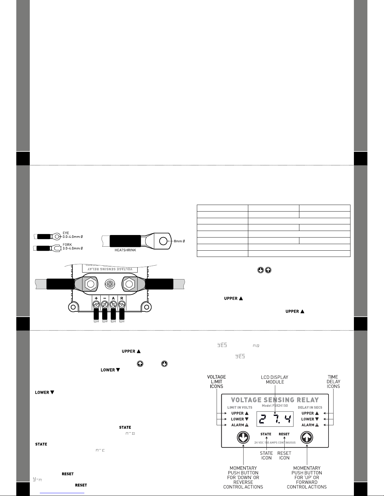
Load Terminals. These are the two large terminals (studs) which are
switching the heavy load connected to the PSR. They are unidirectional (not
line or load conscious) but must be the same polarity. These contacts can be
normally open or normally closed by choice. They are fi tted with M8 nuts and
spring washers and must be correctly terminated. An example of the correct
method of termination is depicted on page 12.
Control Terminals. These are the four small terminals located behind the
contact terminals. They are fi tted with M3 x 6mm cross recessed screws.
The terminals are marked as follows:
+ Positive input for voltage sensing
– Negative input for voltage sensing
A Positive output for alarm trigger
R Positive input for remote override
Please observe polarity when connecting the control terminals. Failure to
observe correct polarity will result in damage to the control circuit of the
PSR and will void warranty. These terminals must be correctly terminated.
An example of the correct method of termination is depicted on page 12.
Operator Interface. The operator interface consists of the switches and
displays used to control and monitor the PSR functions. The control consists
of two buttons marked with up and down arrows. They are used for scroll,
adjust and save operations. The 3 digit LED display is used in conjunction with
the control buttons to adjust the voltage, delay, state and reset functions of
the PSR. These functions are also displayed as text icons and are illuminated
when scrolling through the program settings. See over for illustration.
5
OVERVIEW
Primary Functions
The interVOLT PSR is a user programmable voltage sense relay. The relay
is programmable in terms of voltage sensing, time delay and contact state
which are defi ned below.
VOLTAGE. The PSR can be programmed to activate the load switching
terminals at a desired voltage. An alarm voltage can also be set to output
a separate signal to trigger a remote audio/visual warning device. The
voltage is sensed by the control terminals (marked + and – on the terminal
strip). The control terminals are accurately measuring the input voltage
independent of the switching terminals for more precise sensing. The voltage
is displayed to one decimal place with an accuracy of ± 1%. The VOLTAGE
LIMIT functions can be defi ned as follows:
•
UPPER VOLTAGE LIMIT – this is the higher of any two voltages that the
PSR can be set to activate the load switching terminals when the voltage is
reached. For example, when used as a battery combiner this would be the
‘combine’ voltage which closes the contacts.
• LOWER VOLTAGE LIMIT – this is the lower of any two voltages that the
PSR can be set to activate the load switching terminals when the voltage is
reached. For example, when used as a battery combiner this would be the
‘release’ voltage which opens the contacts.
• AL ARM VOLTAGE LIMIT – this is a setting for any desired voltage which
will trigger the alarm signal and activate any audio/visual warning device
(of maximum 200mA). For example when used as a battery combiner this
would be the minimum voltage considered suitable to enable starting an
engine from the sense batter y.
7
Normally closed state can be used under certain conditions, such as failsafe
switching when used as a load switching relay for example. The state is
displayed as either
or depending on the selection.
RESET. The PSR is factory programmed with defaults for the
aforementioned settings (refer to page 14-15 for details ). Should it be
necessary to reinstate the factory default setpoints it is a simple process to
do so. Please refer to page 14 for details on using the RESET function.
Other Functions
Manual Override Control. In addition to the aforementioned the PSR has
an override function which, when wired to a separate control switch, allows
the operator to remotely override the relay in an emergency. For example,
if the PSR is being used to combine batteries, the remote function can be
used in an emergency to override all the programmed settings and bring the
secondary battery online in the event the primar y battery is drained and/or
fails.
Automatic Status Display. The PSR will automatically display the status
when the setpoints are activated. In the factory default state of normally open
(
) the PSR will display the symbol when the Upper Voltage Limit
is reached and the symbol
when the Lower Voltage Limit is reached.
In normally closed state (
) these will be reversed.
Manual Status Display. At any time the status can be manually checked
by momentarily pushing either up or down control button. This will display
either the
or symbol depending on the condition.
OVERVIEW
9
OVERVIEW
Page 3
10
NOTICE!
The PSR must be properly installed in order to comply with environmental
operating considerations and the manufacturer’s warranty terms and
conditions.
The PSR is constructed from marine grade materials and the electronics
are enclosed in a sealed housing (IP67) however it should, wherever
possible, be installed in a protected environment. Due to the external
termination the PSR is NOT designed to be installed in a location where
water can ‘shor t’ between the terminals.
LOCATION
Select a suitable location where the PSR can be mounted. Ensure there is
adequate ventilation to the heatsink ribs and that the location is free from
excessive vibration and heat. Although sealed for protection from the ingress
of dust and moisture the PSR should not be mounted in a wet environment.
ORIENTATION
The PSR can be mounted in any position vertically or horizontally due to the
solid state design. The PSR should be installed on a hard fl at surface – do
not install on an upholstered or insulated surface. Ensure at least 50mm of
clearance all around from other equipment.
MOUNTING
The PSR should be installed with appropriate fasteners ensuring all
anchor holes are utilised. The mounting hole diameter is 5mm and it is
recommended that a fastener with a diameter (major thread) of no less
than 3.5mm be used. Do not overtighten.
INSTALLATION
12
INSTALLATION
The load switching terminals (M8 stud) and pin drive nut are tin plated copper
for excellent conductivity. The pin-drive nut should NEVER be removed.
It is recommended that proper tinned drawn-copper cable lugs are used for
termination.
All cable lugs must be properly terminated using appropriate tooling in
order to prevent poor contact which can result in overheating of the stud.
An example of the correct method of termination is depicted below.
COPPER LUG
FOR LOAD TERMINATION
CRIMP TERMINALS FOR
CONTROL TERMINATION
VOLTAGE SENSING RELAY
Model PSR12150
12 VDC 150 AMPS CONTINUOUS
14
PROGRAMMING
can again be pressed to save the setting ( if you do not push the two control
buttons to save the setting, it will be saved automatically after 10 seconds at
which point the display will disappear). The [
] will stop fl ashing and
remain steady. The new setting has now been saved.
To move through to the next icon press either the up or down control
button and scroll to the next icon
[ ] which will illuminate and
concurrently show the factory default setting (voltage or time) in the LED
display. Again, if you wish to change the factor y default press the two control
buttons
on the operator interface simultaneously and the selected icon
[
] will begin to fl ash. Use either the up or down control button
to adjust the fi gure to the desired setpoint. Again, press the two buttons
simultaneously to save the setting or just leave and it will save automatically
after 10 seconds. Repeat the aforementioned step for each voltage or time
setting you wish to program.
To change the contact state of the relay use the up
or down control buttons
to scroll through the various settings until
[ ] is illuminated. The LED
display will show the factory default setting of
for normally open.
Press the two control buttons on the operator interface simultaneously and
[ ] will begin to fl ash. Once fl ashing use either the up or down control
button to change the display to
for normally closed. Again, press the
two buttons simultaneously to save the setting or just leave and it will save
automatically after 10 seconds.
If you wish to reset the factory defaults at any time scroll through the various
settings until
[ ] is illuminated. The LED display will show a default of
. Press the two control buttons on the operator interface simultaneously
and the RESET icon
[ ] will begin to fl ash.
11
INSTALLATION
WIRING
In order to ensure safety, good performance and long life the PSR should be
wired according to the method detailed overleaf. Please refer pages 16-33 for
schematics of the various wiring circuits available.
IMPORTANT! Ensure adequately rated cables are used for the maximum
load connected to the PSR. If uncertain, consult your cable supplier quoting
the continuous rating of the load and the length of cable on both input and
output switching terminals. There is a voltage drop and cable size calculator
on the interVOLT website at www.inter volt.com. Undersizing the cable will
result in poor performance, over heating, a reduction in longevity and may
jeopardise your warranty in the event of a failure.
Disconnect the battery supply at the source before attempting any
connection to the control or switching terminals of the PSR.
Install an appropriately rated circuit breaker or fuse as the load protection
for the supply cable to the PSR. The circuit breaker or fuse should be rated
according to the load and should be no greater than the cross sectional
rating of the cable being used. The maximum fuse rating should not exceed
150 Amps.
Connect all wiring to the PSR control (M3 screw) terminals ensuring correct
polarity. Failure to observe correct polarity will result in damage to the
control circuit of the PSR. In the event the PSR is incorrectly reverse polarity
connected, the unit must be returned to vendor for servicing.
13
Set Up
Once the control (sense) wires are connected the PSR is ready to be
programmed if necessar y. Keep in mind the factory default settings may
suit your application and there may be no requirement to adjust them.
The factor y default settings are as follows:
PSR12150 for 12VDC PSR2 4150 for 24VDC
Upper Voltage Limit 13.7 Volts 27.4 Volts
Upper Time Delay 5 Seconds
Lower Voltage Limit 12.8 Volts 25.6 Volts
Lower Time Delay 5 Seconds
Alarm Voltage Limit 12.0 Volts 24.0 Volts
Alarm Time Delay 10 Seconds
State of Contacts Normally Open (n-o)
If you wish to adjust the settings please use the following procedure:
Press the two control buttons
on the operator interface
simultaneously. The LED display will indicate a series of scrolling bar
segments for a few seconds as it initialises (performing internal system
check). Once initialised the display will show the factory default Upper
Voltage Limit of 13.7 for a 12VDC system or 27.4 for a 24VDC system and the
UPPER icon [
] will be illuminated.
If you wish to change the default setting, press the two control buttons
again simultaneously and release after the [
] starts to fl ash.
Once fl ashing use either the up or down control button to adjust the setting
in 0.1V increments to reach the desired setpoint. Once selected both buttons
PROGRAMMING
15
PROGRAMMING
Once fl ashing use either the up or down control button to change the
display to
(to reset) or (not to reset). Again, press the two buttons
simultaneously to save the setting or just leave and it will save automatically
after 10 seconds. If
is selected all factory default settings will be
instituted.
Page 4
16
CONNECTION
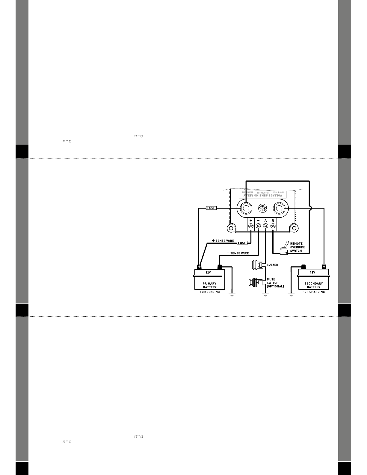
BATTERY COMBINER FOR CHARGING
FIGURE I
One of the primar y applications for the PSR is its suitability for combining
dual batteries for charging from a single source whilst still maintaining
isolation between the batteries. A typical application for this is where there
is a requirement to charge two batteries (or banks of batteries) and there
is only one charging source available. As it is not good practice to parallel
charge two batteries the option of installing an automatic device such as
the PSR to both control and isolate the batteries is a desirable alternative
to other charging methods. Case example as follows:
Scenario: A vessel is equipped with two banks of 12V batteries, a main
starting bank and a house bank. The only charging source is a single
alternator on the main engine which is generally under utilised due to
minimal cycling of the starting bank. The owner would also like to charge the
house bank from the alternator without fear of discharging the starting bank
in the event the house battery is inadvertently discharged.
Resolution: The PSR can be programmed to direct the charging source to
the house battery via the starting battery while still maintaining complete
isolation when not activated. This will ensure the correct maintenance of the
auxiliary batter y and at the same time prevents the auxiliary batter y from
discharging or ‘draining’ the starting battery.
IMPORTA NT! The PSR must be set to normally open (
) when used in
this application (
is factory default).
18
CONNECTION
• Alarm Voltage Limit – this is the setpoint you will program as the low
voltage warning limit for your main or starting battery. In the event this
batter y is discharged for whatever reason a signal can be output to a
remote alarm (audible, visual or both) to alert the operator. The default
setting is 12.0 Volts for a 12V system but this voltage can be programmed
to the desired setting.
• Alarm Time Delay – this is the setpoint you will program as the time
(in seconds) you wish to delay the alarm function. This setpoint provides
a delay between the time the alarm voltage limit is reached and when it
is activated. This is useful to prevent nuisance alarm warnings when the
voltage dips below the desired level, when cranking the engine for example.
Note:
In addition to the aforementioned functions, the PSR has several other
features which can be utilised to aid and assist the user and/or installer.
These features include Manual Override Control, Automatic Status Display,
and Manual Status Display. Please refer to page 7 for details.
20
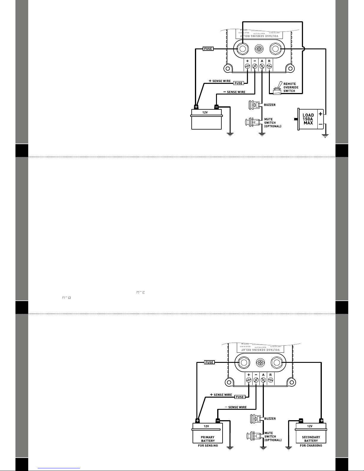
LOW VOLTAGE DISCONNECT
FIGURE II
Another specialised application for the PSR is its use as a low voltage
disconnect to prevent inadvertent discharge of battery banks. The PSR can
be connected in series with the load and programmed with any desired
voltage (with time delay) in order to open the load contacts when the battery
is discharged. Additionally, it can be programmed with a higher voltage limit
to re-connect the load automatically but only when the battery is charged to a
suitable voltage. Case example as follows:
Scenario: A vessel is fi tted with a bow thruster which is serviced by a house
bank of 24V batteries. To prevent complete discharge of the batteries when
the thruster is being used, the owner wishes to automatically disconnect the
bow thruster at a desired voltage in order to preserve the batteries for other
uses.
Resolution: The PSR can be programmed to disconnect the bow thruster
automatically when the voltage drops to a preset level. Additionally, a time
delay can be set to prevent the bow thruster from shutting down on start up
when the voltage dips temporarily due to the inrush current.
IMPORTA NT! The PSR must be set to normally open (
) when used in
this application (
is factory default).
CONNECTION
17
CONNECTION
When used as a battery combiner the PSR can be user programmed with the
following settings:
• Upper Voltage Limit – this is the setpoint you will program as the ‘combine’
voltage i.e. when the starting battery reaches this setting the relay will
close and automatically connect the house batter y for charging. The default
setting is 13.7 Volts for a 12V system but this voltage can be programmed to
the desired setting.
• Upper Time Delay – this is the setpoint you will program as the time
(in seconds) you wish to delay the ‘combine’ function. This setpoint provides
a delay between the time the upper voltage limit is reached and when it is
activated. This is useful to prevent cyclic switching when the voltage is at
the switching threshold.
• Lower Voltage Limit – this is the setpoint you will program as the ‘release’
voltage i.e. when starting battery reaches this setting the relay will open
and automatically disconnect the house battery from charging. The default
setting is 12.8 Volts for a 12V system but this voltage can be programmed to
the desired setting.
• Lower Time Delay – this is the setpoint you will program as the time
(in seconds) you wish to delay the ‘release’ function. This setpoint provides
a delay between the time the lower voltage limit is reached and when it is
activated. This is useful to prevent cyclic switching when the voltage is at
the switching threshold.
19
CONNECTION
FIGURE I
21
When used as a low voltage disconnect the PSR can be user programmed
with the following settings:
• Upper Voltage Limit – this is the setpoint you will program as the
‘re-connect’ voltage for the load i.e. when the battery reaches this setting
the relay will close and automatically connect the load on the output.
This setpoint could be set 1.0V higher than the disconnect voltage as a
‘hysteresis’ thus ensuring the battery has reached a suitably charged level
before re-connecting. Assuming a 24VDC system, this voltage could be set
anywhere from 27.0 Volts to 28.0 Volts as an example.
• Upper Time Delay – this is the setpoint you will program as the time
(in seconds) you wish to delay the ‘re-connect’ function. This setpoint
provides a delay between the time the upper voltage limit is reached and
when it is activated. This is useful to allow for the desired voltage to be
stabilised for any given time period before reconnecting the load. In a
typical application this setting would be set to around 10 seconds.
• Lower Voltage Limit – This is the setpoint you will program as the
‘disconnect’ voltage i.e. when the batter y reaches this setting the relay
will open and automatically disconnect the load on the output. This
setpoint is dependent upon the particular application, type of battery and
charging regime. The installer would need to determine the appropriate
setting after researching this information. Assuming a 24VDC system, this
voltage could typically be set anywhere from 24.0 Volts to 26.0 Volts as an
example.
CONNECTION
Page 5
22
• Lower Time Delay – this is the setpoint you will program as the time
(in seconds) you wish to delay the ‘disconnect’ function. This setpoint
provides a delay between the time the lower voltage limit is reached and
when it is activated. This is useful to prevent cyclic switching and allows
for voltage transients and dips to be taken into consideration.
• Alarm Voltage Limit – this is the setpoint you will program as the low
voltage warning limit for the battery. In the event this battery is discharged
for whatever reason a signal can be output to a remote alarm (audible,
visual or both) to alert the operator. Assuming a 24VDC system this could
be set to 24.0 Volts as a typical example.
• Alarm Time Delay – this is the setpoint you will program as the time
(in seconds) you wish to delay the alarm function. This setpoint provides
a delay between the time the alarm voltage limit is reached and when
it is activated. This is useful to prevent nuisance alarm warnings when
the voltage dips below the desired level, when cranking the engine for
example.
Note:
In addition to the aforementioned functions, the PSR has several other
features which can be utilised to aid and assist the user and/or installer.
These features include Manual Override Control, Automatic Status Display,
and Manual Status Display. Please refer to page 7 for details.
CONNECTION
24
AUTOMATIC PARALLELING OF BATTERIES
FIGURE III
The PSR can also be used as a paralleling switch for multiple batter y banks.
The advantage with this particular application is that the PSR can be utilised
as an automatic load connect switch. The PSR is programmed with the
desired voltage and delay limits to connect a second battery to the primary
batter y when required. For example a starting battery can be connected
via the PSR to any secondar y battery (of the same voltage) to automatically
provide assistance to the starting battery in an emergency or as a back-up.
Case example as follows:
Scenario: A vessel is fi tted with a 12V starting battery bank. In addition there
is an onboard generating set which is also fi tted with a 12V starting battery.
The genset batter y is independent and is separately charged from another
source. The owner of the vessel would like to use the genset battery as a
back-up to the main batter y in an emergency situation.
Resolution: It is possible, using the PSR, to utilise the genset battery as
an emergency back-up to assist the main starting battery by paralleling
both batteries automatically. In automatic mode the PSR is programmed
with voltage and delay setpoints to allow the second battery to connect
when required and disconnect when the primary battery voltage returns to
normal. The PSR can also be used as a manual parallel switch when used as
a conventional relay (refer page 32).
IMPORTA NT! The PSR must be set to normally closed (
) when used in
this application (
is factory default).
CONNECTION
26
• Alarm Voltage Limit – this is the setpoint you will program as the low
voltage warning limit for the battery. In the event this battery is discharged
for whatever reason a signal can be output to a remote alarm (audible,
visual or both) to alert the operator. Assuming a 12VDC system this could
be set to 12.0 Volts as a typical example.
• Alarm Time Delay – this is the setpoint you will program as the time
(in seconds) you wish to delay the alarm function. This setpoint provides
a delay between the time the alarm voltage limit is reached and when
it is activated. This is useful to prevent nuisance alarm warnings when
the voltage dips below the desired level, when cranking the engine for
example.
Note:
In addition to the aforementioned functions, the PSR has several other
features which can be utilised to aid and assist the user and/or installer.
These features include Manual Override Control, Automatic Status Display,
and Manual Status Display. Please refer to page 7 for details.
CONNECTION
23
FIGURE II
CONNECTION
25
When used for automatic paralleling of batteries the PSR can be user
programmed with the following settings:
• Upper Voltage Limit – this is the setpoint you will program as the
‘disconnect’ voltage to isolate the second battery after the primar y battery
again reaches a suitably charged level. Assuming a 12VDC system, this
voltage could be set anywhere from 13.5 Volts to 15.0 Volts as an example.
• Upper Time Delay – this is the setpoint you will program as the time (in
seconds) you wish to delay the ‘disconnect’ function. This setpoint provides
a delay between the time the upper voltage limit is reached and when it
is activated. This is useful to allow for the desired voltage of the primary
batter y to be stabilised before disconnecting the secondary batter y.
In a typical application this setting would be set to around 10 seconds.
• Lower Voltage Limit – this is the setpoint you will program as the ‘connect’
or paralleling voltage for the load i.e. when the battery reaches the desired
voltage the relay will activate and close the load contacts thus connecting
the two batteries. Assuming a 12VDC system, this voltage could be set
anywhere from 12.0 Volts to 13.5 Volts as an example.
• Lower Time Delay – this is the setpoint you will program as the time
(in seconds) you wish to delay the ‘parallel’ function. This setpoint provides
a delay between the time the lower voltage limit is reached and when it is
activated. As an example this setting could be adjusted to 5 seconds which
would allow for momentar y voltage dips and transients before activating
the connect function.
CONNECTION
27
12 VDC 150 AMPS CONTINUOUS
FIGURE III
CONNECTION
Page 6
28
AUTOMATIC LOAD SWITCHING
FIGURE IV
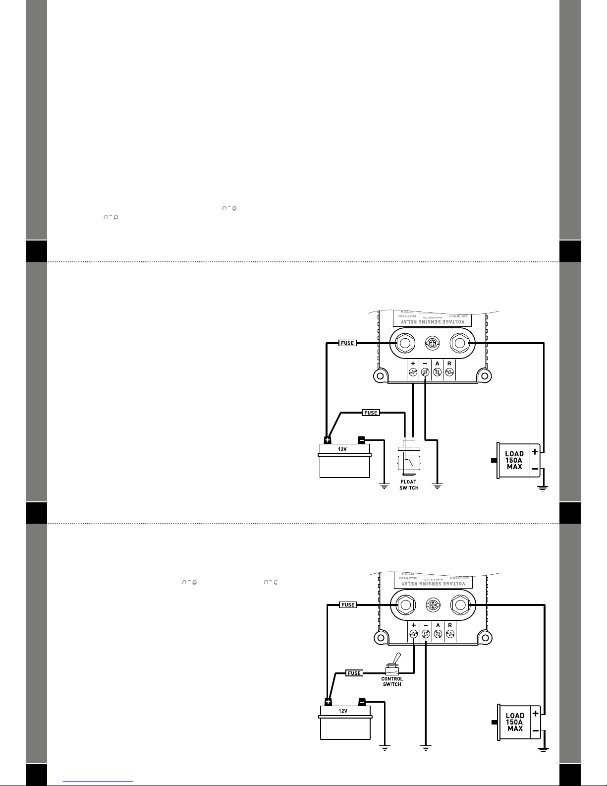
The PSR is ideally suited to automatic load switching (up to 150 Amps) by
using the control terminals for sensing a desired voltage range. This function
is particularly useful in remote, often unmanned installations, where there
is a requirement to automatically switch heavy loads on and off as required
at the same time protecting equipment from collateral damage such us
undervoltage or overvoltage situations. Case example as follows:
Scenario: In a remote solar powered application a submersible 24V DC
water pump is used to draw water from a bore which is then pumped
some distance into a large storage tank. The pump is driven from a bank of
batteries and is controlled by an automatic fl oat switch in the storage tank.
In this instance the pump is not protected from under voltage should the
batter y bank drain.
Resolution: The PSR can be utilised to switch the pump via the fl oat switch
but only when the voltage is at the desired level. The automatic fl oat switch
is wired in series with the control terminals (positive or negative). The PSR
is then programmed with the desired upper and lower voltage limits to
disconnect the pump when the voltage drops below an acceptable limit and
not reconnect it until the batteries are again charged to a suitable level.
IMPORTA NT! The PSR must be set to normally open (
) when used in
this application (
is factory default).
CONNECTION
30
• Lower Time Delay – this is the setpoint you will program as the time
(in seconds) you wish to delay the ‘disconnect’ function. This setpoint
provides a delay between the time the lower voltage limit is reached and
when it is activated. This is useful to prevent cyclic switching and allows for
voltage transients and dips to be taken into consideration.
• Alarm Voltage Limit – this is the setpoint you will program as the low
voltage warning limit for the battery. In the event this battery is discharged
for whatever reason a signal can be output to a remote alarm (audible,
visual or both) to alert the operator. Assuming a 24VDC system this could
be set to 23.0 Volts as a typical example.
• Alarm Time Delay – this is the setpoint you will program as the time
(in seconds) you wish to delay the alarm function. This setpoint provides
a delay between the time the alarm voltage limit is reached and when
it is activated. This is useful to prevent nuisance alarm warnings when
the voltage dips below the desired level, when cranking the engine for
example.
Note:
In addition to the aforementioned functions, the PSR has several other
features which can be utilised to aid and assist the user and/or installer.
These features include Manual Override Control, Automatic Status Display,
and Manual Status Display. Please refer to page 7 for details.
CONNECTION
32
CONVENTIONAL HEAVY DUTY RELAY
FIGURE V
The PSR can be used as a conventional, heavy duty relay for switching
DC loads up to 150 Amps continuous. It has the added advantage of being
programmable for either normally open (
) or normally closed ()
state. The control terminals are simply wired in series with the control device
(switch or relay) and activated as required. In this instance the voltage limits
and time delays can be programmed out of range of any activation setpoint
i.e. so the limits do not have any infl uence over the control of the relay.
CONNECTION
29
When used for automatic load switching the PSR can be user
programmed with the following settings:
• Upper Voltage Limit – this is the setpoint you will program as the ‘reconnect’ voltage to engage the pump when the desired level is reached.
This setpoint could be set 1.0V higher than the disconnect voltage as a
‘hysteresis’ thus ensuring the battery has reached a suitably charged level
before re-connecting. Assuming a 24VDC system, this voltage could be set
anywhere from 25.0 Volts to 27.0 Volts as an example.
• Upper Time Delay – this is the setpoint you will program as the time
(in seconds) you wish to delay the ‘re-connect’ function. This setpoint
provides a delay between the time the upper voltage limit is reached and
when it is activated. This is useful to allow for the desired voltage to be
stabilised for any given time period before reconnecting the load.
In a typical application this setting would be set to around 10 seconds.
• Lower Voltage Limit – This is the setpoint you will program as the
‘disconnect’ voltage i.e. when the batter y reaches this setting the relay
will open and automatically disconnect the pump. This setpoint is
dependent upon the particular application, type of battery and charging
regime. The installer would need to determine the appropriate setting
after researching this information. Again, assuming a 24VDC system, this
voltage could typically be set anywhere from 23.0 Volts to 24.0 Volts as an
example.
CONNECTION
31
FIGURE IV
CONNECTION
33
FIGURE V
CONNECTION
Page 7
34
SPECIFICATIONS
PSR Voltag e Sensing Relay PSR12150 PSR24150
Application Voltage 12VDC System 24VDC System
O
perating Voltage Sensing
Operating Voltage Switching
9VDC - 18VDC
Continuous Contact Rating
150 A (rated @ 50
°C)
Momentary Contact Rating 500 Amps DC for a period of 10 seconds @ 10% duty cycle
(rated @ 40°C)
Contact State
Environmental protection
Electrical Protection
Standby Current Draw
Standby Current Draw
U
ser selectable, normally open or closed
IP67 (internal components only)
Thermal overload shutdown, automatic overload
protection of sensing circuit. Low voltage disconnect.
Un-switched 10mA @ 13.5VDC and 23mA @ 27.0VDC
Switched 35mA @ 13.5VDC and 55mA @ 27.0VDC
Operating Temperature
-25°C to +70°C (n
ote continuous rating above)
Alar m Output Signal Equal to input voltage to 200mA maximum.
Operating Humidity Ideally should not exceed 95%.
Enclosure Housing E-coated A360 (ADC 3) die cast aluminium
Enclosure Cover and
Terminal Protector
Injection moulded electrical grade ABS/ PC
Load Terminals Tin plated copper stud, stainless hardware. M8
Control Terminals Tin plated brass contact, stainless hardware. M3
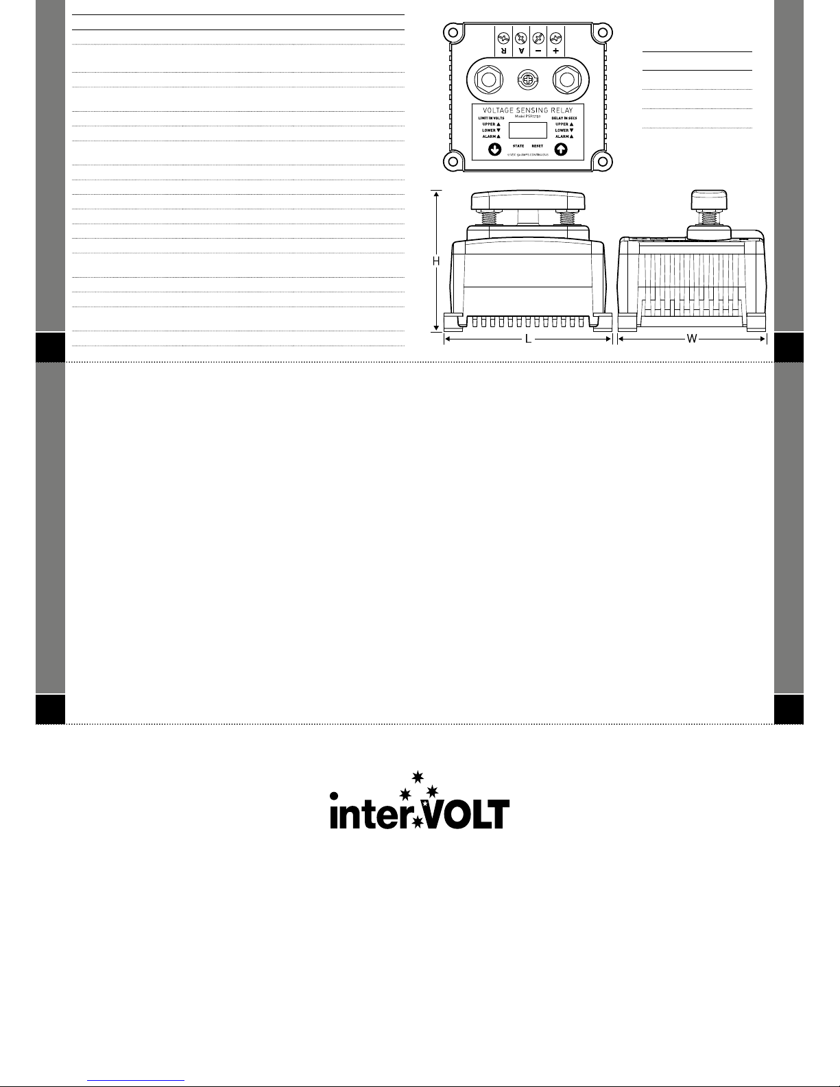
Dimensions Footprint – 86mmW x 97mmL over all
Profi le – 81.5mmH overall (including terminal cover).
Weight 505 grams
36
WARRANTY POLICY
interVOLT products are warranted for a period of 24 months against faulty
materials and/or workmanship from date of purchase by the end user subject
to proof of purchase. In the event proof of purchase is not provided, and at
the discretion of the manufacturer, the warranty shall be 24 months from
manufacturer’s date of sale to the merchant from whom the product was
purchased. interVOLT’s 24 month warranty is subject to the following terms and
conditions.
The goods must be installed and operated in accordance with the manufacturer’s
recommendations and instructions set out within this booklet.
In the event of a claim the goods are to be returned to the original point of
purchase with a copy of the merchant invoice or the relevant merchant invoice
number.
In the event of a claim any associated expenses including diagnosis, removal,
and/or installation of the goods is the responsibility of the client including any
freight costs.
The warranty shall be void where the goods have been used for a purpose for
which they are not intended, or altered in any way that is detrimental, or opened
or tampered with by an unauthorised party, or damaged by mechanical abuse, or
contaminated by water or other substances, or damaged by incorrect application.
Save and except for the express warranty set out above and to the maximum
extent permitted by law, all conditions and warranties which may at any time be
implied by the common law, Trade Practices Act, Fair Trading Act or any other
State or Federal Act are excluded. To the extent that these cannot be excluded
and where the law permits, the manufacturer in respect of any such condition
or warranty shall be limited at their option to the repair or the replacement of the
goods or the supply of equivalent goods or refunding the cost of the goods.
35
DIMENSIONS
Reference Dimension
L 97mm
W 86mm
H 81.5mm
Did you know?
• interVOLT power conversion products are proudly designed and developed
in Australia for both domestic and international markets. All R&D is
carried out at our premises in Perth, Western Australia and all IP is owned
by our parent company Amelec Australia Pty Ltd.
• interVOLT products are designed to cope with the demands of the
harshest applications and will operate in high temperature, high humidity
environments. They are constructed of quality marine grade materials and
when applied and installed correctly are designed to provide many years of
continuous service.
• interVOLT’s current range includes voltage converters, power
conditioners, lighting dimmers and battery equalizers with a strong
emphasis on quality, performance and value. We are committed to
continual product development in the DC power conversion fi eld.
• Intervolt products comply with both Australian and European Standards
for Electro-Magnetic compatibility. They are supported by a 100%
factory backed 24 month warranty against faulty components and/or
workmanship (see warranty policy for comprehensive information).
• interVOLT is a registered trademark of Amelec Australia Pty Ltd an
import, export, distribution and manufacturing company with a reputation
for quality goods, superior service and competitive pricing.
inter VOLT is a r egistered trademark of Amele c Austr alia Pty Ltd in Australi a a nd various other countries
inclu ding the UK and USA and as such is prote cted by the releva nt laws of the cou ntry of registratio n.
© 2011. All rights reserv ed. The entire conte nts of this instruction man ual shall remain the pr operty of
Amel ec Austr alia Pty Ltd and should not be repro duced withou t writ ten permission.
Manual No. PSRG1 R1 -0
Manufactured by Amelec Australia Pty Ltd
16 Parkinson Lane, O’Connor, WA 6163, Australia
www.intervolt.com
16VDC - 38VDC
33VDC Maximum
150 A (rated @ 40°
C)
 Loading...