

Page 1
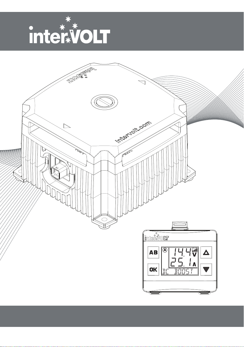
DCC Pro
In-Vehicle DC-DC
Battery Charger
12VDC 25 AMPS
(VERSION R2.0)
INSTALLATION & OPERATION MANUAL
Page 2

WELCOME
Thank you for choosing an interVOLT product...
Intervolt Pty Ltd is a wholly Australian owned and operated private
company and the proud owner of the interVOLT brand, a trademark
which is registered in over 20 countries worldwide.
We have been producing specialised power conversion products for over
15 years. All our products are designed, developed and assembled
in-house at our premises in Perth, Western Australia from both local
and imported components.
Our design ethos is based on quality, performance and value, and we are
committed to product development in the DC power, control and
conversion field. With roots in the commercial marine, transport, alternate
energy and allied industries, we have expanded into the consumer market
with dedicated products such as the DCC Pro.
InterVOLT products are designed to cope with the demands of the
harshest applications in high temperature and high humidity environments.
They are constructed of quality materials and designed to provide many
years of continuous service.
Again, thank you for choosing an interVOLT product and supporting
Australian innovation, technology, intellectual property and of course, jobs.
Page 3

OVERVIEW .............................................................. 2
Introduction ............................................................ 2
Outline ................................................................... 3
Application.............................................................. 4
Kit Contents............................................................ 5
FUNDAMENTALS .................................................... 6
Charging Methods ................................................... 6
Control Modes ........................................................ 7
Layout - the Charging Device ..................................... 8
Layout - the Remote Display ...................................... 9
Standard Wiring Diagram ....................................... 10
Wiring using two Charging Devices........................... 11
INSTALLATION ...................................................... 12
Planning the Installation .......................................... 12
Installation Essentials ............................................. 13
Installing the Charging Device .................................. 14
Installing the Data Cable ......................................... 15
Installing the Remote Display ................................... 16
Wiring the Charging Device ..................................... 17
Connection and Configuration .................................. 18
Installation Steps ................................................... 19
OPERATION........................................................... 25
Operating Brief ...................................................... 25
Operator Control and Monitoring.............................. 27
Operator Convenience Settings ................................ 30
System Status....................................................... 32
TROUBLESHOOTING .............................................. 33
Alert Conditions..................................................... 33
Error Conditions .................................................... 34
Frequently Asked Questions..................................... 35
SPECIFICATIONS ................................................... 36
DIMENSIONS ........................................................ 37
APPENDIX ............................................................ 38
Fundamentals in Detail ........................................... 38
WARRANTY POLICY .............................................. 41
CONTENTS
1
Page 4

OVERVIEW
Introduction
Following its release in 2015 the DCC Pro has enjoyed outstanding success in
the overland vehicle market both in Australia and overseas. We are now pleased
to introduce version 2.0 which features a number of functionality and
performance upgrades oering even greater ‘value for money’ than the original.
Just some of the great features on the new DCC Pro 2.0:
• Designed to charge an auxiliary battery using the main battery and/or solar
power as input sources, quickly and eciently.
• Proven three stage charging methodology in both ‘battery to battery’ and
'solar to battery’ charging processes, including MPPT.
• Solar charging is now current limited to 25 Amps so input is no longer
restricted to the number of panels connected (total Wattage).
• Double stacked printed circuit boards provide a compact footprint allowing
for easy location and xing in an engine bay.
• All external components are designed to operate under high ambient/humid
conditions and are rated to IP67 for dust and moisture protection.
2
• Capable of charging a wide range of battery chemistry types including a
specic curve for LiFePO4 Lithium batteries (with inbuilt battery management
system).
• The exibility to adapt to almost any application in any vehicle, old or new,
simple or complex with or without an ECU controlled electrical system.
• A truly universal ‘Plug and Play’ system which allows multiple set-up and
conguration options for simplied installation and operation.
• Provides the operator with the ability to monitor the charging status of the
auxiliary battery from the comfort of the cabin.
• A true stand-alone charging system which can be implemented without
interference or modication to the host vehicle’s factory wiring.
Page 5

Outline
In a standard dual or multiple battery arrangement, the system will consist of a
starting (or main) battery and secondary (or auxiliary) batteries. For clarity and
conciseness we will refer to these throughout the manual as the main and
auxiliary batteries.
Our vision for the DCC Pro was a device which would not only provide an
autonomous charging method for any auxiliary battery, but would reliably,
accurately and repeatedly provide feedback to the operator on the status of the
charging and maintenance process. In order to provide this information we
integrated a visual display. The addition of a remote display also provides a level
of operator input, allowing some control of the device, such as selection of
battery types for example. The development of a true remote user interface
enabled the concept to evolve into the product you have purchased today.
The DCC Pro consists of three main components. Together, these form a
stand-alone charging system and are all that is necessary, aside from the
external wiring, to implement a fully operational charging and maintenance
system for one auxiliary battery or bank (batteries in parallel). These
components are:
1. The Charging Device. This is the power conversion component of the
system. It is a high power, yet compact package which is designed to be
installed in the engine bay of the vehicle.
OVERVIEW
2. The Remote Display. This is the separate control and monitoring device
which is designed to be installed in the vehicle cabin in easy view and reach of
the operator. It has a backlit LCD display and four control buttons.
3. The Data Cable. This is the interconnect harness that enables the Charging
Device and Remote Display to communicate with each other.
This manual contains comprehensive information on the installation,
set-up and use of the DCC Pro and is applicable to this model only (version
R2-0). Whilst every care has been taken in the preparation of this manual,
Intervolt Pty Ltd oers no guarantee, express or implied, and accepts no
liability for any inaccuracies, errors or omissions in its content.
Specications are subject to change without notice.
3
Page 6

OVERVIEW
Application
The DCC Pro has been designed specically for use in 4WDs, RVs, buses,
coaches, caravans, campers or any vehicle with a 12VDC electrical system
where there is a requirement to charge one or more secondary (auxiliary)
batteries using the starting (main) battery as the primary source. It is not
designed or warranted for use in marine applications.
The DCC pro utilises the three step or ‘stage’ charging principle for maintaining
an auxiliary battery by using the main battery as the primary source and solar
power as the supplementary source. The three stages combined represent a full
charging cycle. Although there are many variants of this concept, the basic
three stages, when implemented correctly, are all that is required to ensure
proper charging of any auxiliary battery. The stages are categorised as boost,
absorption and oat, details of which are explained in the appendix of this
manual. In boost stage the charger is operating in constant current (CC) mode
and in absorption and oat stages it is in constant Voltage (CV) mode.
The DCC Pro is pre-programmed with charging regimes for the following
battery types which can be selected in the conguration (set-up) process:
• Standard Lead Acid – sealed and ooded cell versions
• Absorbed Glass Mat – aka AGM
• Gelied Electrolyte – aka GEL
• Lead Calcium
• LiFePO4 – with Battery Management System (BMS) only (not suitable for
other Lithium battery types).
4
The information on the following pages of this manual detail the functions of
the DCC Pro and the settings which are best suited for your application and
installation. If you are performing the installation it is important to read this
manual in its entirety. If you are the operator it is only necessary to read the
‘Operation’ section. The appendix section contains specic information on the
fundamentals of the DCC Pro and is optional but recommended reading.
NOTE: It is not essential to use the Remote Display included. The DCC Pro’s
Charging Device is autonomous and will operate with or without the
Remote Display connected. It is necessary to use the Remote Display for
programming purposes, however it is not necessary to permanently install
the display if it is not desired.
Page 7
Kit Contents
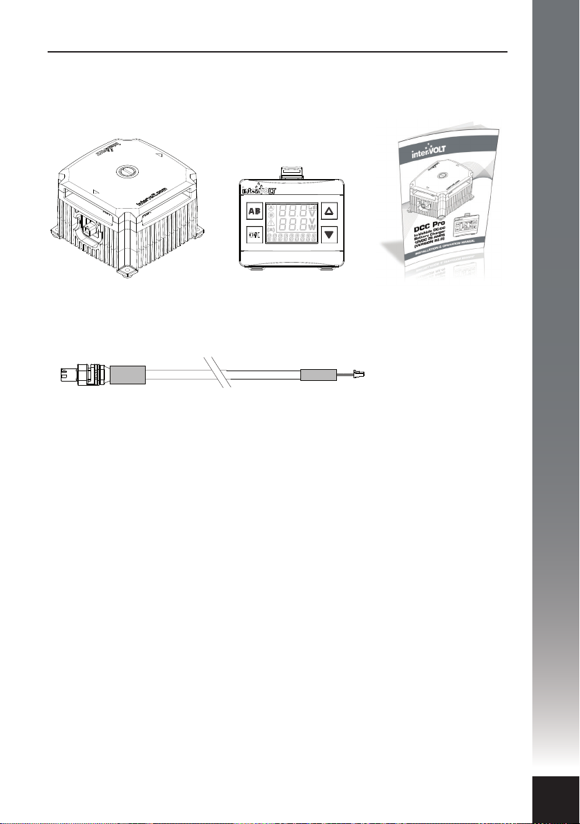
You have purchased the DCC Pro retail package code number DCC1225ACK-RP.
The package contains the components depicted below:
OK
OVERVIEW
DCC Pro Charging Device
Code: D
All components are available to purchase separately. Data Cables are available
in a range of optional lengths. In the event you wish to add in a second
charger for example, it would not be necessary to purchase another display
but simply order another Charging Device and Data Cable of the appropriate
length.
The code numbers for the components are detailed below:
• DCC1225ACD: Automotive Charging Device 12 Volts DC 25 Amps
• DCC0001ARD: Automotive Remote Display complete with bracket
• DCC3000CTR: Data Cable 3 metres Charging Device to Remote Display
• DCC4000CTR: Data Cable 4 metres Charging Device to Remote Display
• DCC6000CTR: Data Cable 6 metres Charging Device to Remote Display
• DCC9000CTR: Data Cable 9 metres Charging Device to Remote Display
CC1225ACD
DCC Pro 4mtr Data Cable
Code: DCC4000CTR
DCC Pro Remote Display
Code: D
CC0001ARD
DCC Pro Printed Manual
Code: DCCAUTG1 R2-0
5
Page 8
FUNDAMENTALS
Charging Methods
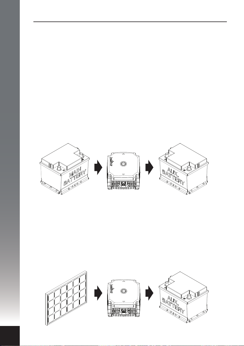
There are two methods the DCC Pro utilises for charging an auxiliary battery.
Although employing the same three stage process for both battery and solar
input sources, the methodology is dierent. Both methods can be utilised at the
same time thus providing a complete charging solution for your vehicle’s
auxiliary battery system.
Charging the auxiliary battery from the main: The battery to battery
charging method employs power conversion to step up the source Voltage to a
higher level before being regulated at a Voltage determined by the battery type
(chemistry) selected. In topology terms, this is dened as a boost/buck
conversion process where the input Voltage is stepped up in the boost process
and stepped down (regulated) in the buck process. The main battery is the
priority charging source if and when available. This is because, by comparison,
the vehicle’s alternator can generally deliver much higher current when the
engine is running than most solar power installations.
6
Charging the auxiliary battery from solar power: The solar to battery
charging method uses the higher available Voltage (18–28 OCV) to extract the
maximum power from a solar source by employing Maximum Power Point
Tracking algorithms (MPPT). The MPPT function provides a benet of up to 30%
greater eciency in performance over a standard (PWM) type regulator. It
should be noted at this point that the solar panel is directly connected and
should be unregulated. Use of a regulator will not allow the MPPT charging
control to operate correctly and as a result will be detrimental to the charging
and maintenance of your auxiliary battery.
Page 9
Control Modes
There are two optional modes which control how the charging system operates.
These modes are selectable in the initial set-up process when installing the
device and control the charging process in dierent ways. The control modes
can always be changed if necessary but the initial set-up and installation steps
need to be repeated in order to do so. The control modes are dened and
explained as follows:
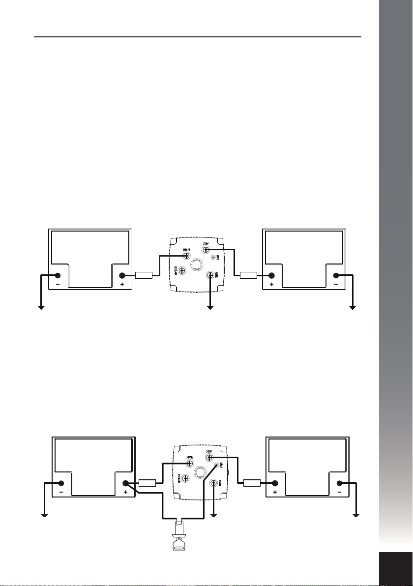
Voltage Control Mode: Voltage mode is the default (factory) mode and allows
the charging process to operate automatically, independent of the host vehicle.
This mode is recommended for installations where it is not viable or necessary to
use the host vehicle’s ignition switch to enable/disable the Charging Device.
Voltage mode would primarily be used where the Charging Device is located in a
caravan or camper trailer for example, and thus a long way from a switched
ignition source.
CHARGING
DEVICE
FUNDAMENTALS
MAIN
BATTERY
FUSE FUSE
AUXILIARY
BATTERY
Ignition Control Mode: Ignition mode is selectable at the set-up stage of the
installation process and is the alternative to Voltage mode. This mode is
recommended for installations where the auxiliary battery is mounted in the
host vehicle, in the engine bay or under the tray for example. In Ignition mode a
control wire is permanently connected to the Charging Device from the vehicle’s
electrical system to allow dependent control via the host vehicle’s ignition
switch. In this mode the Charging Device can be enabled or disabled when the
ignition switch is turned on or o respectively.
CHARGING
DEVICE
MAIN
BATTERY
FUSE FUSE
AUXILIARY
BATTERY
IGNITION
SWITCH
7
Page 10
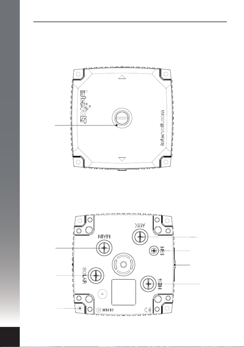
FUNDAMENTALS
Layout - Charging Device
LED
GLOW
RING
Top View With
Terminal Cover
8
MAIN
BATTERY
POSITIVE
TERMINAL
SOLAR
PANEL
POSITIVE
TERMINAL
MOUNTING
FEET
Top View Without
Terminal Cover
interVOLT Model
DCC1225ACD
Battery to Battery
Charging Device
12VDC - 12VDC
25 Amps max.
Note: Images above shown approximately half actual size.
AUXILIARY
BATTERY
POSITIVE
TERMINAL
IGNITION
CONTROL
TERMINAL
REMOTE
DISPLAY
OUTPUT
COMMON
NEGATIVE
TERMINAL
Page 11
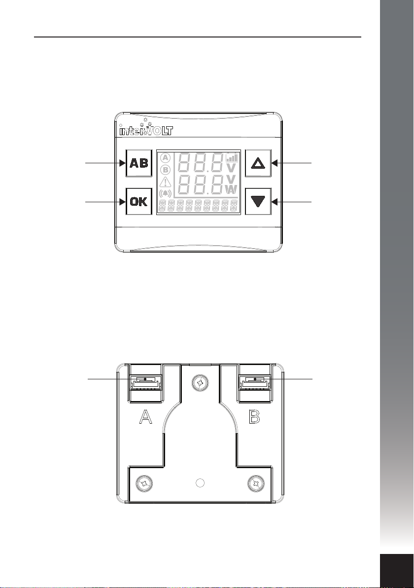
Layout - Remote Display
Front View
FOR SWITCHING
BETWEEN TWO
CHARGING DEVICES.
ALSO USED AS
BACK AND EXIT
BUTTON.
FUNDAMENTALS
‘UP’ SELECTION
OR HIGH
BRIGHTNESS
CONTROL.
CONFIRMATION
SELECTION BUTTON.
ALSO USED TO
TOGGLE BETWEEN
DEFAULT AND
ALTERNATE SCREEN.*
* See Page 28 for further information.
CHARGING
DEVICE
INPUT
A
‘DOWN’ SELECTION
OR LOW
BRIGHTNESS
CONTROL. ALSO
USED TO TURN OFF
BACKLIGHT.
Back View
CHARGING
DEVICE
INPUT
B
Note: Images above shown approximately actual size.
9
Page 12
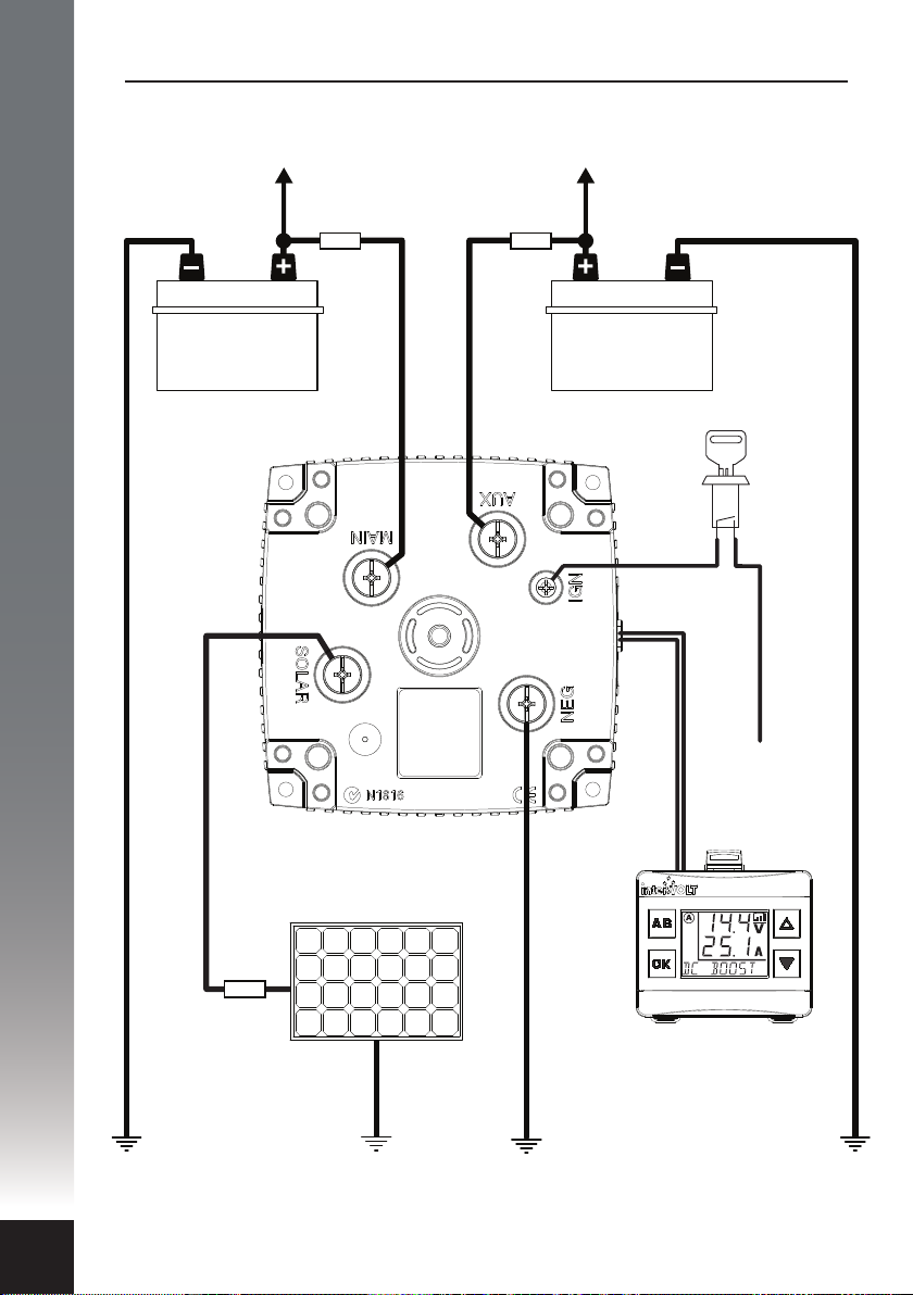
FUNDAMENTALS
Standard Wiring Diagram
12V
MAIN
TO
ENGINE
FUSE
interVOLT Model
DCC1225ACD
Battery to Battery
Charging Device
12VDC - 12VDC
25 Amps max.
TO AUXILIARY
EQUIPMENT
FUSE
12V
AUX
OPTIONAL
IGNITION
SWITCH
+ IGNITION SWITCH SU PPLY
DATA CABLE
10
CHARGING
DEVICE
FUSE
SOLAR
PANEL
REMOTE
DISPLAY
NOTE: Do not connect auxiliary battery to Charging Device
until system has been congured.
Page 13
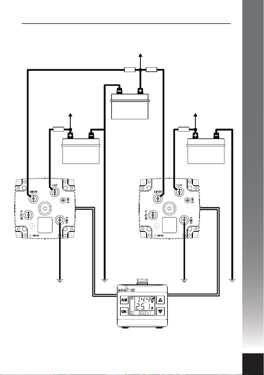
Wiring using two Charging Devices
TO
ENGINE
FUNDAMENTALS
CHARGING
DEVICE A
interVOLT Model
DCC1225ACD
Battery to Battery
Charging Device
12VDC - 12VDC
25 Amps max.
TO AUXILIARY
EQUIPMENT
FUSE
12V
AUX 1
FUSE
12V
MAIN
FUSE
CHARGING
DEVICE B
interVOLT Model
DCC1225ACD
Battery to Battery
Charging Device
12VDC - 12VDC
25 Amps max.
TO AUXILIARY
EQUIPMENT
FUSE
12V
AUX 2
DATA CABLE A
REMOTE DISPLAY
NOTE: Do not connect auxiliary battery to Charging Device
until system has been congured.
DATA CABLE B
11
Page 14

INSTALLATION
Planning the installation
IMPORTANT: In order to ensure safety, high performance and
long life the DCC Pro should only be installed by a suitably
qualied tradesperson.
Plan the installation according to the location of the main and auxiliary
batteries. The Charging Device can be situated anywhere in the circuit (subject
to using the appropriate cable size) and does not need to be located directly
next to either battery. Please consider the number of cables required when
planning the install as the location could result in extra wiring. For example if
the DCC Pro is required to charge a battery in a caravan it may be better to
mount the Charging Device in the caravan itself rather than the vehicle but this
may depend on where the Remote Display needs to be located.
Consideration should be given to the wiring layout. The DCC Pro has been
designed so that cables can enter the device from any direction, even from one
side only, without having to cross over. Crimp terminals are recommended over
soldered lugs and should be terminated to automotive quality standards.
Incorrect or poor crimping is not only a mechanical issue (wire separating from
terminal) but will also cause Voltage drop and potential overheating of the
conductor as a result. Using the correct wire size for the application is
imperative. The table on page 17 details the minimum conductor size according
to the run length.
12
For complete protection it is necessary to fuse each positive conductor. The fuse
should be installed as close as possible to the battery. Fusing is required to
protect the vehicle in the event of a short circuit – a cable coming o a terminal
and contacting the chassis for example. The DCC Pro itself is fully protected by a
range of internal protection devices. The fuse should be no smaller in rating
than recommended in the chart on page 17 and no larger than the rating of the
cable being used.
NOTE: All wiring should be terminated and routed but not
connected to the Charging Device at this time. In order to
congure the device the connection must be made in
conjunction with the set-up steps depicted on pages 18–24.
Page 15

Installation Essentials
Common faults often arise as a result of the installation. A poor installation will
result in poor performance of the system, placing unnecessary stress (both
electrically and physically), on all the components involved. Furthermore, this can
result in safety issues such as breakdowns and in worst case scenarios even re.
This is why we state that the DCC Pro should only be installed by a suitably
qualied tradesperson.
Please observe the following protocols when undertaking a dual battery
installation:
1. To avoid Voltage drop, use correct wire gauge size according to the run length.
Using undersized wiring is the most common cause of Voltage drop. Copper is
expensive and it is tempting to reduce the cost of an installation by using smaller
gauge wire however this is detrimental to both performance and safety. Do not
be tempted!
2. Use bolt-down midi style fuses. Do not use blade fuse holders. Many
o-the-shelf style blade fuse holders use poor quality materials. The metal
contacts cannot handle thermal cycling and quickly become loose, thereby losing
conductivity. Manual reset circuit breakers are acceptable but check for de-rating
factor under elevated temperatures.
INSTALLATION
3. Use good quality copper compression lugs for all termination and correct
tooling to ensure proper crimping. Sub-standard crimping creates resistance in
the circuit which can produce a ‘hot spot’. Under heavy current, the heat
generated from this point can be enough to melt plastics. The high temperature
can also be conducted to other components causing failure.
4. Terminate all negative wiring at a common grounding point. Bad grounding
creates resistance in the circuit resulting in Voltage drop and can be dicult to
diagnose if the circuit is not under load. Ensure that all grounding points
connected to the body/chassis have good electrical conductivity and are
protected from corrosion.
5. Many installations use heavy duty connectors tted in the circuit, often
between the DC DC charger and a caravan/camper for example. Ensure any
connectors tted between the Charging Device and batteries are of high quality
and correctly rated for the wire size used. If a connector is required, we
recommend only Genuine Anderson brand. Poor quality connectors will result in
resistance in the circuit and a potential ‘hot spot’.
13
Page 16
INSTALLATION
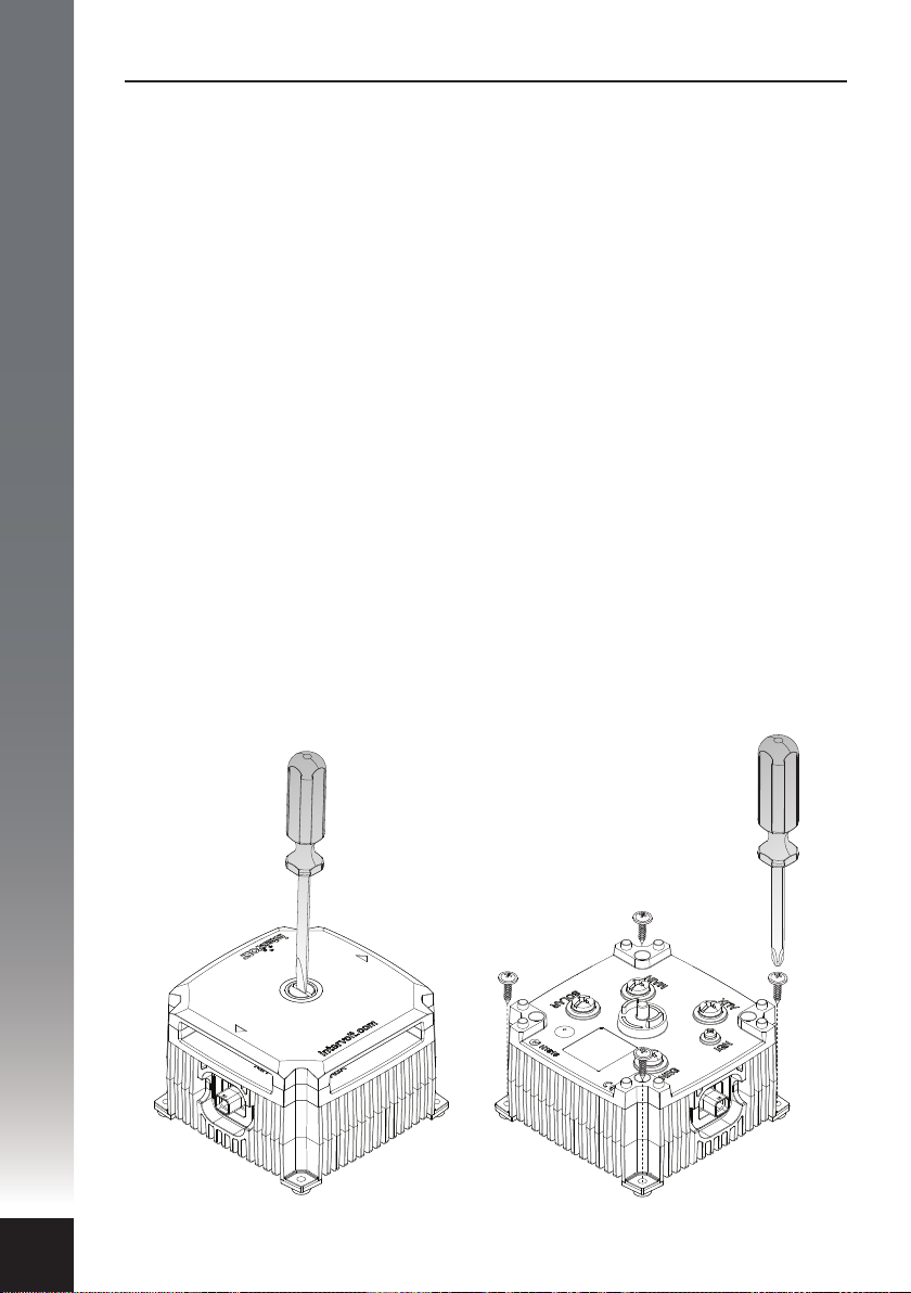
Installing the Charging Device
The DCC Pro Charging Device has been designed to cope with demanding
conditions and can be installed in the vehicle’s engine compartment. Care must
be taken when performing the installation to ensure performance, longevity and
of course, safety. Installing the device too close to a turbocharger for example
may not only force the device into thermal shut down but could also result in
catastrophic failure.
Select a suitable location where the Charging Device can be mounted ensuring
adequate ventilation to the heatsink ns, free from excessive vibration and heat.
The electronics are enclosed in a sealed housing however the device, where
possible, should be installed in a protected environment. The Charging Device is
NOT designed to be installed in a location where water can regularly ‘short’
between the terminals.
As it is of solid state design, the Charging Device can be mounted in any position
vertically or horizontally. It should be oriented so that the LED Glow Ring
indicator is clearly visible to the installer/operator. It must be installed on a hard
at surface – not an upholstered or insulated surface. Ensure at least 30mm of
clearance all around from any other equipment.
The Charging Device should be xed with appropriate fasteners ensuring all four
anchor holes are utilised. If mounted on a vertical surface the Data Cable
socket should be oriented to the side or downwards.
14
NOTE: Remove the terminal cover
before using any tools to fasten the
Charging Device in position.
Page 17
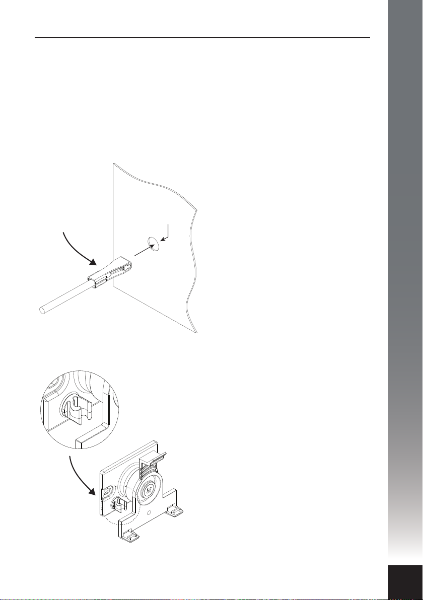
Installing the Data Cable
The Data Cable is the communication link between the Charging Device and the
Remote Display. It has a sealed connection at the device end and unsealed
connector at the display end. If the Charging Device is installed in the engine
bay, a 10mm diameter feed-through hole must be drilled in the rewall for the
Data Cable.
DO NOT FORCE THE DATA CABLE THROUGH AN EXISTING FACTORY WIRING
GROMMET AS THIS COULD RESULT IN DAMAGE TO THE CONNECTOR.
The Data Cable must be fed through
the hole from the engine bay side as
the sealed connector will not pass
Connector protector
to remain in place
until ready to plug in
10mm Ø
through the hole. A rubber grommet
is tted to the cable and must be
utilised to prevent damage to the
cable sheath from any sharp metal
edges.
The Data Cable is tted with a PVC
‘clamshell’ protector over the Remote
Display connector plug. This is to
protect the plug from damage when
being routed into the vehicle cabin.
The protector should only be removed
when you are ready to plug into the
Remote Display.
INSTALLATION
Data Cable
retaining
clips
There are two plastic clips located on
the Remote Display mounting base.
These are used to secure the Data
Cable and relieve any strain on the
connector. The cable can simply be
pushed into the clip after the
connector has been plugged in to the
socket on the rear of the Remote
Display but not until it is mounted
(see page 16).
15
Page 18
INSTALLATION
Installing the Remote Display
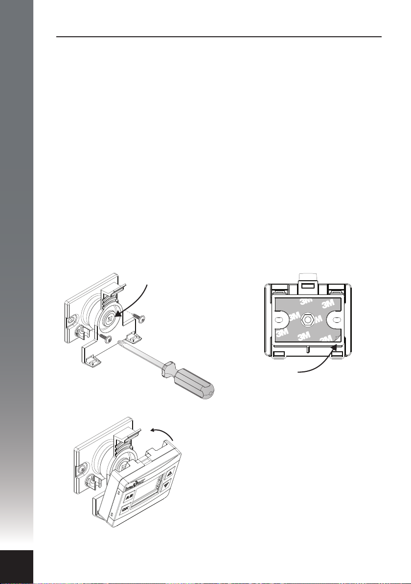
The DCC Remote Display is designed to be installed in the cabin of the vehicle,
on the dash or console. It should be shielded from excessive heat and located
away from direct sunlight if possible.
A user adjustable ball joint allows for the housing to swivel through a range of
positions to best suit the operator.
A tensioning screw in the centre of the mounting bracket can be utilised to
adjust and maintain the Remote Display in the desired position. This screw
should not be over-tightened.
There are two methods provided for xing the mounting base to the surface,
details as follows:
Option A - Screw Fixing:
This method utilises two suitable
fasteners (not supplied) to attach the
mounting base to the surface as per
the diagram below.
Ball Joint
Tensioning
Screw
Option B – Adhesive Fixing:
This method utilises the self-adhesive
foam backing tape to adhere the
mounting base to the surface as per
the diagram below.
Peel o backing
lm to apply
The mounting base is designed to hold
the Remote Display. Place the display
bottom rst into the bracket and
pinpoint the two location tabs provided.
Tilt the display back until the top tab
locates in position with an audible ‘click’.
The display can be removed at any time
by pushing the thumb lever gently back
and releasing the housing assembly. Do
not press on the lens as this may result in
it cracking.
16
Page 19
Wiring the Charging Device
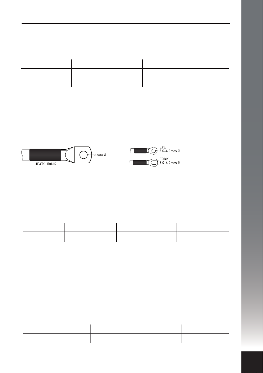
Using the correct cable gauge size for the task is paramount to performance
and safety. Please refer the table below for the minimum recommended cable
size (cross section) required in order to prevent Voltage drop.
Cable Run Length Minimum Conductor Size Recommended SAE Equivalent
1-5 Metres 6 mm² 8 B&S/AWG (7.91mm²)
5-9 Metres 10 mm² 6 B&S/AWG (13.56mm²)
All cable lugs must be properly terminated using appropriate tooling in
order to prevent poor contact which can result in overheating of the stud.
An example of the correct method of termination is depicted below.
INSTALLATION
COPPER LUG FOR
POWER TERMINATION
The DCC Pro is fully protected electronically against catastrophic failure. It is
mandatory however that inline fuses are tted to protect the wiring in the event
of an external short circuit. The fuse rating should not be less than the
continuous current rating of the wiring. The table below details the
recommended fuse size for all required wiring.
Main Solar Auxiliary
40A minimumFuse rating To solar panel spec. 30A minimum
There are four large power terminals, one each for the main and auxiliary
batteries, one for the solar panel and one for the negative connection. A lug
with a 6mm diameter hole should be used for terminating these four cables.
There is a single, smaller control terminal which is used when Ignition Control
mode is implemented. Spring washers are not required.
DO NOT USE POWER TOOLS TO FASTEN TERMINAL SCREWS
All terminals should be fastened with hand tools and care should be taken not
to over-torque the screws. The torque settings are detailed in the table below.
CRIMP LUGS FOR
IGNITION TERMINATION
Main/Auxiliary/Solar/Negative Ignition
5.0 NmMaximum torque rating 1.5 Nm
17
Page 20

INSTALLATION
Connection and Configuration
A step-by-step guide
In some applications, the DCC Pro can be installed and connected straight out
of the box without any changes to the conguration. In other situations it is
necessary to change these defaults, a dierent battery type for example, as
detailed below (see Charging Methods section on page 6 for explanation).
For safety reasons, the battery type and control mode can only be changed
during set-up (conguration mode) before the auxiliary battery is connected.
Of course, these selections can be changed at any time but the auxiliary battery
must be disconnected in order to do so.
In default state the conguration is based on a standard battery to battery
charging installation and assumes the following:
1. The auxiliary battery is a standard lead acid type (sealed or unsealed).
2. The system is not controlled by the vehicle’s ignition circuit.
The Remote Display is initially used for conguring the Charging Device upon
installation. Most importantly the Remote Display allows for selection of
dierent battery types (chemistries) and the control mode, Voltage Sense or
Ignition Control (see explanation on page 7).
18
The following options are available for selection:
• Standard Lead Acid – displayed as 1 LEAD ACID on the Remote Display
during set-up or SLA in short form.
• Absorbed Glass Mat – displayed as 2 AGM on the Remote Display during
set-up and in short form.
• Gelied Electrolyte – displayed as 3 GEL on the Remote Display during
set-up and in short form.
• Lead Calcium – displayed as 4 CALCIUM on the Remote Display during
set-up or LCA in short form.
• LiFePO4 Lithium – displayed as 5 LFP BMS on the Remote Display during
set-up and in short form.
The following pages illustrate the step by step conguration process for
installing the Charging Device and Remote Display. If there is a need to
change the battery type and control mode, this process must be completed
in the order depicted for the DCC Pro to operate correctly.
Page 21
1
INSTALLATION
Important! Please read before attempting any connection
• All steps must be completed in the order indicated. Do not
connect the auxiliary battery cable until step 13. For safety reasons
there are specic settings that are locked out once the auxiliary
battery is connected.
2
• In step 7 it is important to note that if the button is not held
OK
until the audible ‘beep’ is heard an error message will be displayed.
• If the battery type selected needs to be changed after step 13 is
completed, the auxiliary battery must be disconnected before
re-commencing at step 7.
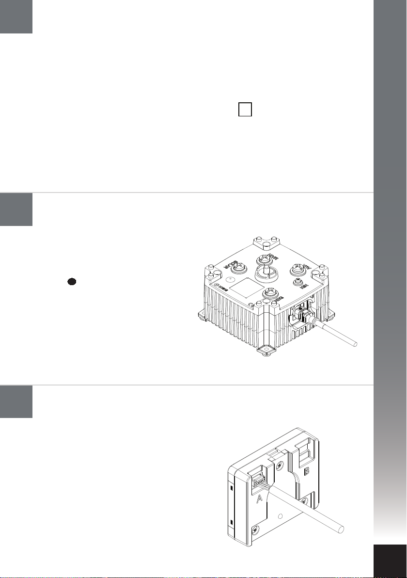
Connect the Data Cable to the Charging Device
Remote Display needs only be used for programming
The Charging Device end of the Data
Cable is tted with a sealed 6-way
connector plug. The plug is marked with
a spot of identifying colour indicating
the top of the connector. The plug should
be gently pushed into the mating
connector socket until it ‘clicks’ into
position. To check the latch has engaged
gently pull the connector – it should not
move. If there is a need to remove the
connector, please see page 24 for
instructions, do not just pull out.
3
Connect the Data Cable to the Remote Display
Remote Display needs only be used for programming
The Remote Display end of the Data Cable
is tted with an unsealed connector plug.
The plug is tted with a plastic ‘clamshell’
(for protection) which can now be
removed for installation. The plug should
be gently pushed into the mating
connector socket until it ‘clicks’ into
position. To remove the connector press
the tab/latch and pull out. When using one
Charging Device either socket can be
utilised.
19
Page 22
INSTALLATION
4
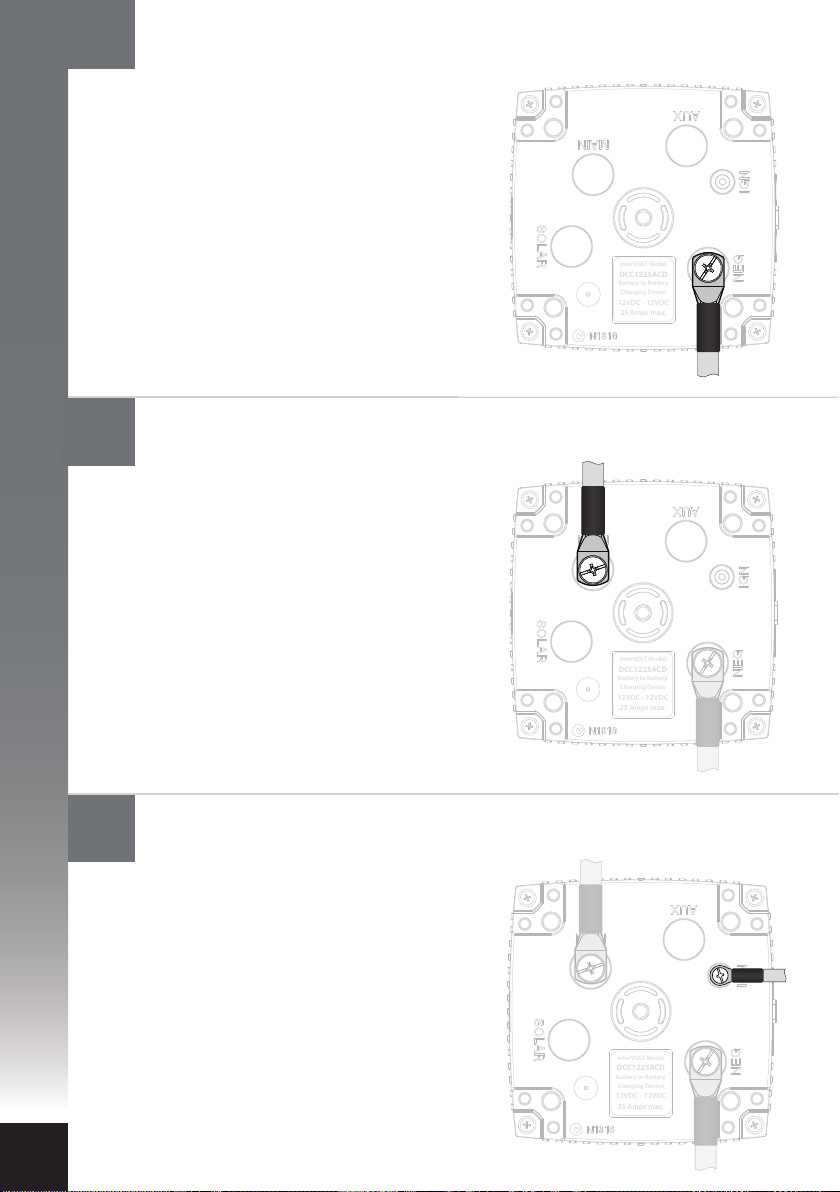
Connect the negative power cable to the Charging Device
The negative power cable should be
connected to the Charging Device rst.
This should be fastened to the terminal
marked NEG using the special screw
provided. Connect the other end of the
negative to the main battery negative
(recommended) or directly to the
chassis, ensuring the connection has
good contact. Ensure the auxiliary
battery negative is either connected to
the NEG terminal of the Charging
Device or the chassis.
interVOLT Model
DCC1225ACD
Battery to Battery
Charging Device
12VDC - 12VDC
25 Amps max.
20
5
6
Connect the main battery cable to the Charging Device
The main positive power cable is the
next to be connected. Check the in-line
fuse is removed prior to connecting the
cable. Connect the Charging Device end
of the positive cable to the terminal
marked MAIN using the special screw
provided. Connect the other end of the
cable to the main battery positive. Insert
the fuse into the inline fuse holder. The
Charging Device is now powered and
the LED indicators should be ashing
interVOLT Model
DCC1225ACD
Battery to Battery
Charging Device
12VDC - 12VDC
25 Amps max.
white intermittently.
Connect the ignition cable to the Charging Device
(if utilised)
The ignition cable is the next to be
connected, if the intention is to use
Ignition Control Mode (see page 7).
Keep in mind that the control mode
setting is optional and, even if the
ignition wire is connected, it does not
necessarily need to be implemented in
set-up mode.
Important! Do not connect
auxiliary battery cable at
interVOLT Model
DCC1225ACD
Battery to Battery
Charging Device
12VDC - 12VDC
25 Amps max.
this time.
Page 23
7
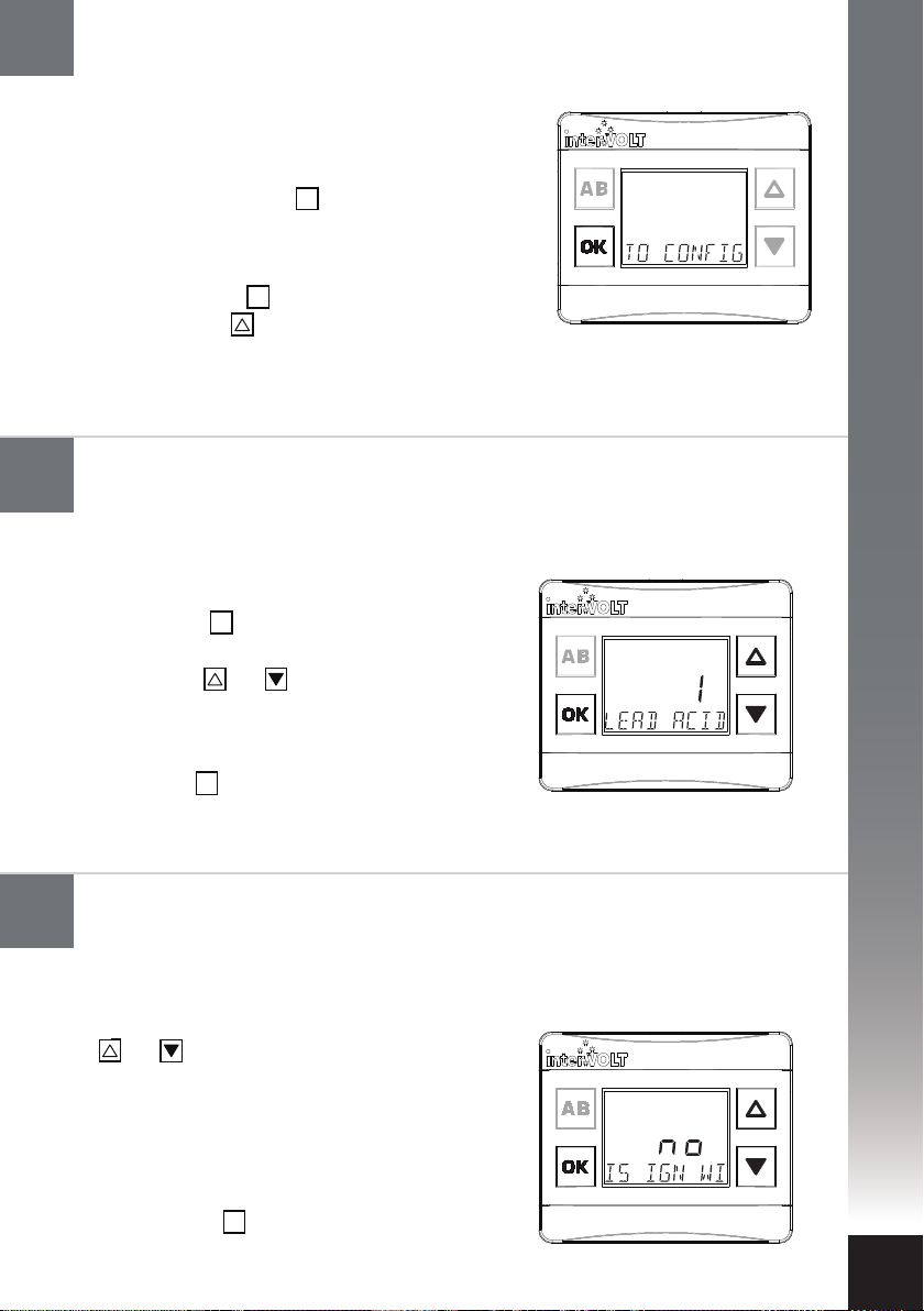
Configure the Charging Device: Initialising set-up mode
This step need only be done if changing the factory default settings
Conguring or ‘setting up’ the Charging Device is the
next step in the sequence. To initiate set-up mode
follow the steps below:
I. Press and hold the button until an audible
‘beep’ is heard and a scrolling message reads
‘To configure press up’. The LED Glow
Ring will now indicate purple intermittently.
II. Release the button.*
III. Press the button to initiate the set-up mode
and continue to next step.
* If an error message is displayed please see page 34.
OK
OK
INSTALLATION
8
9
Configure the Charging Device: Selecting battery type
Following the last step (7) above, the message
‘BATT TYPE’ will appear. To select the auxiliary
battery type, follow the steps below:
I. Press the button to enter the battery type
selection menu.
II. Use the and buttons to scroll and view
the available options (as outlined on page
page 18).
III. Once the desired battery type is visible,
press the button to conrm and continue
to next step.
OK
OK
Configure the Charging Device: Ignition wire control
Following the last step (8) above, the message ‘IS
IGN WIRE CONNECTED’ will appear. You will
need to answer this question to proceed. Use the
and scroll buttons to select one of the two
following options:
I. If you have not connected the ignition
control wire select no and proceed to step 12.
II. If you have connected the ignition control
wire to the Charging Device select YES.
III. Press the button to conrm and continue
to next step.
OK
21
Page 24
INSTALLATION
10
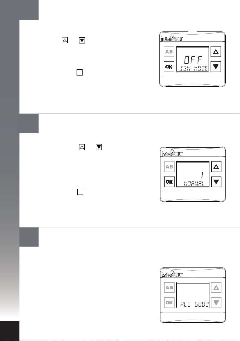
Configure the Charging Device: Ignition control mode
Following the last step (9) conrm if you
want to enable ignition control mode.
Use the and scroll buttons to select
one of the two following options:
I. To disable ignition mode select OFF
II. To enable ignition mode select On
III. Press the button to conrm and
continue to next step.
OK
11
12
Configure the Charging Device: Ignition control setting
The next step is to conrm the ignition control
setting. Use the and buttons to select one
of the two following options:
I. Select NORMAL for conventional
(non ECU) charging systems.
II. Select LOW for ECU controlled
electrical systems.
III. Press the button to conrm and
continue to next step.
OK
Configure the Charging Device: Confirming configuration
Upon successful completion of the above, the
following conrmation message should appear:
ALL GOOD - this indicates your selections have
been sent to the device and accepted. It does not
conrm the integrity of your wiring installation.
22
In the event a SYS message error is displayed,
disconnect, then reconnect the main battery
positive cable and re-commence step 7. If the
error persists re-check the Data Cable connection.
If this does not resolve the problem, please refer
to the troubleshooting information on page 34.
Page 25
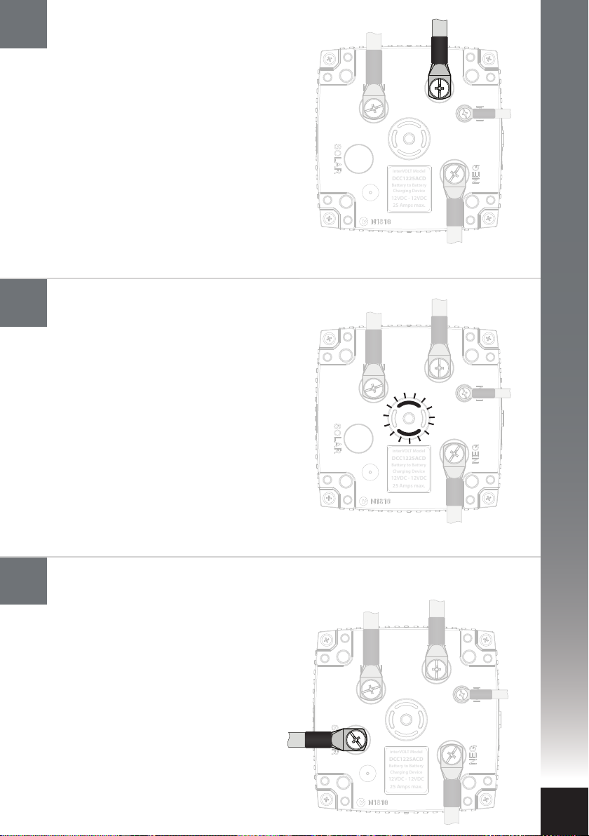
13
Connect the auxiliary battery cable
to the Charging Device
The auxiliary positive battery cable should
now be connected. Check the in-line fuse
is removed prior to connecting the cable.
Connect the Charging Device end of the
positive cable to the terminal marked AUX
using the special screw provided. Connect
the other end of the cable to the auxiliary
battery positive. Insert the fuse into the
inline fuse holder and continue to next
step. Ensure the auxiliary battery
negative cable is connected to complete
the circuit.
interVOLT Model
DCC1225ACD
Battery to Battery
Charging Device
12VDC - 12VDC
25 Amps max.
INSTALLATION
14
15
Confirming operation
The Charging Device should now be active.
Subject to the state of the main and auxiliary
batteries, the Charging Device will now enter
stand by mode or a charging stage. See
pages 39-40 for more information.
As a result the LED indicators will reect the
current stage, for example if the current
stage is ‘oat’ they will illuminate green
continuously. If a solar panel is to be
connected continue to next step.
interVOLT Model
DCC1225ACD
Battery to Battery
Charging Device
12VDC - 12VDC
25 Amps max.
Otherwise continue to step 16.
Connect the solar panel power cable (if available)
The solar panel positive power cable
can now be connected. Check the
in-line fuse is removed prior to
connecting the cable. Connect the
output positive cable from the solar
panel to the terminal marked SOLAR
using the special screw provided.
Reinstall the fuse into the inline fuse
holder. Subject to the state of the
auxiliary battery, the Charging Device
may enter solar mode. See page 6
for more information. Continue to
next step.
interVOLT Model
DCC1225ACD
Battery to Battery
Charging Device
12VDC - 12VDC
25 Amps max.
23
Page 26
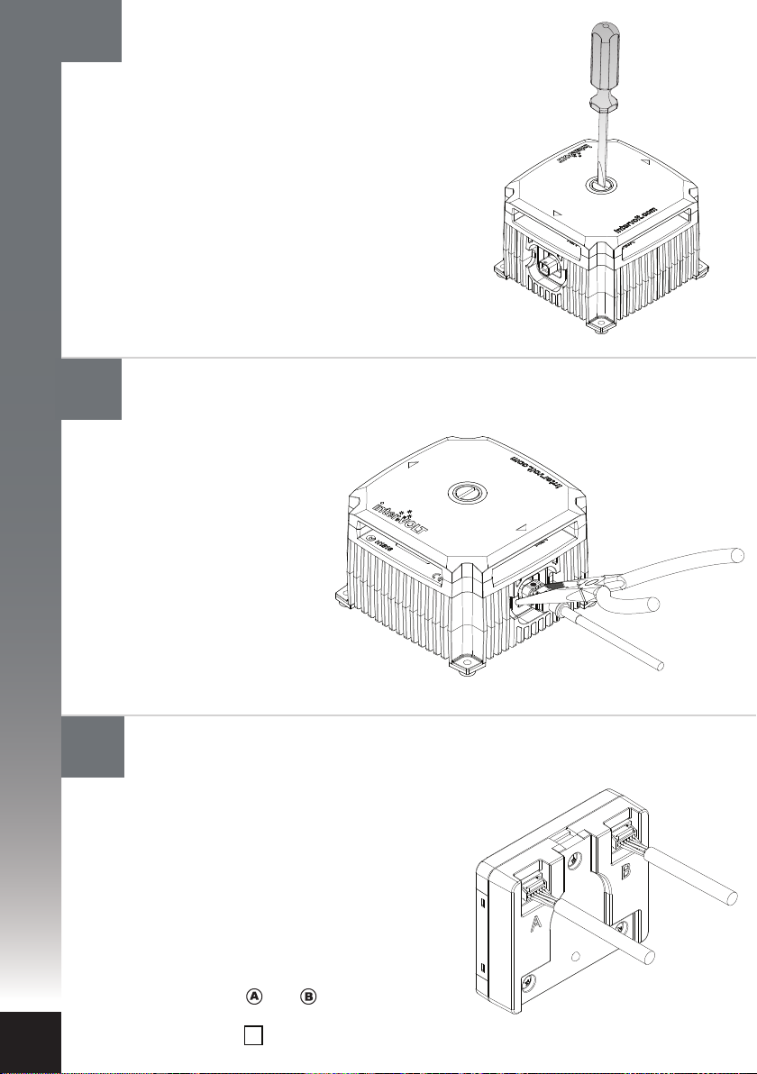
I
NSTALLATION
16
Reinstall the terminal cover
Locate the terminal cover according
to the arrows. The cover is indexed
and must t into the locating pins in
order for the Glow Ring to operate
correctly. The installation is now
complete, however if you have a
second Charging Device to install
please proceed to step 18.
24
17
18
Unplugging the Data Cable from the Charging Device.
(if necessary)
Using a pair of needle nose
pliers, apply a little pressure
to the sides of the Data
Cable plug and gently
withdraw the plug
assembly. As pressure is
applied to the plug the
locking tab momentarily
deforms and is released
from the mating recess.
Connect a second Charging Device (if available)
If a second Charging Device is to be connected to
the Remote Display please implement as follows:
I. Unplug the data connector of the existing
Charging Device for the Remote Display.
II. To install the second Charging Device
repeat steps 2 to 14.
III. Once successfully installed reconnect the
original data connector.
IV. The two Charging Devices will now be
displayed as and on the LCD screen.
It is possible to switch between devices by
toggling the button (see operation section).
AB
Page 27
Operating Brief
The DCC Pro is a fully self-contained Charging Device for in-vehicle battery to
battery charging. The kit is supplied complete with the Remote Display and the
Data Cable however, aside from initial programming of the operating mode and
battery type, it is not essential to use the Remote Display if not required. In fact,
for certain applications, the Charging Device is available separately as are all the
other components. A eet of vehicles may be an example where charging is
required but monitoring is not. In this example, multiple Charging Devices
could be purchased but only one Remote Display is required to program all.
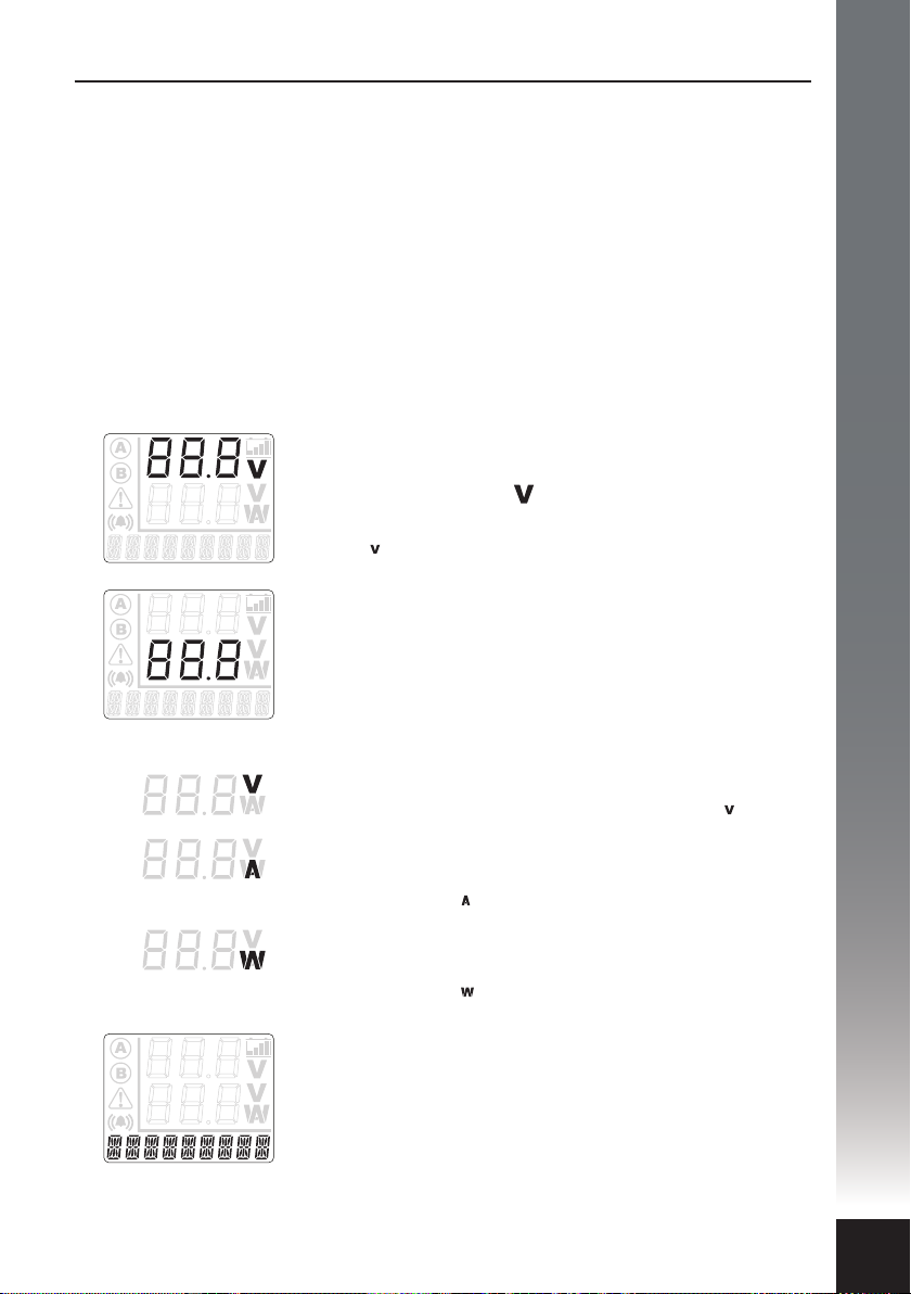
The Remote Display provides valuable feedback to the operator on the charge
state of the auxiliary battery and the status of the Charging Device as depicted
below:
OPERATION
1.
2.
3.
The upper numeric display
This is the top three digit numeric character set.
In conjunction with the icon, this indicates the
auxiliary battery Voltage to one decimal place
e.g.14.4 .
The lower numeric display
This is the bottom three digit numeric character set.
This is a multi-function indicator which can be toggled
in standard operating mode (not stand by) to switch
between auxiliary battery charging current/power and
main battery Voltage.
i
ii
iii
The Voltage icon
This indicates the main battery Voltage e.g.12.4 ; or
The Amperage icon
This indicates the current in Amps for battery to battery
charging e.g. 25.1 ; or
The power icon
This indicates the power in Watts for solar to battery
charging e.g. 350 .
The message display
This is the multi-function nine digit alphanumeric
character set which displays the charging source
followed by the charging stage status e.g. PV BOOST.
In the alternate screen the pre-programmed battery
type will be displayed e.g. AGM BATT.
25
Page 28
OPERATION
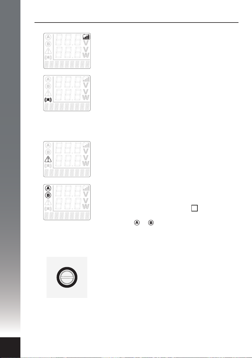
4.
5.
6.
7.
The battery icon
This indicates the auxiliary charging cycle status.
Please see page 28 for a detailed description of this
function.
The audible alarm icon
This indicates the audible alarm is enabled. The
audible alarm operates in conjunction with the DCC
Pro’s warning system and is enabled by default.
The audible alarm can be disabled at any time.
Please see page 30 for directions on conguring
the audible alarm.
The alert icon
This indicates an alert condition. Please see page 33
for a detailed description of this function.
The Charging Device icons
These indicate which battery Charging Device is
currently being displayed, when there are two
Charging Devices in use. Toggling the button
changes from one Charging Device to the other,
displaying the or icon accordingly. If there is
only one Charging Device connected, these icons will
not be displayed.
AB
26
8.
The LED Glow Ring
This indicator is located on the top (terminal cover) of
the Charging Device. The LED Glow Ring is an integral
part of the DCC Pro’s control and monitoring system,
changing colour and state according to the status of
the Charging Device. Please see page 32 for detailed
information on the LED Glow Ring.
Page 29
Operator Control and Monitoring
Once installed and congured the DCC Pro Remote Display can be used to
monitor a range of functions and provide valuable feedback to the operator on
the status of the dual battery system.
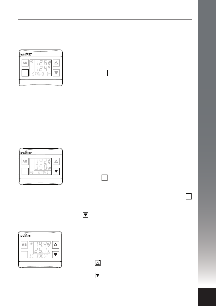
Display-On-Demand
At any time the Charging Device is in stand by mode
the Remote Display can be ‘woken’ by momentarily
OK
pressing the button. This applies in either Ignition or
Voltage Control Mode. The following information will
be temporarily displayed:
• Auxiliary Battery Voltage. This is always displayed as
the upper numeric set.
• Main Battery Voltage. This will be displayed as the
lower numeric set.
• Charging Device Status. This is displayed as STAND
BY on the multi-function character set.
Display On/O Control
OK
OPERATION
OK
OK
In order to conserve energy, the Remote Display is
automatically deactivated when solar charging ( PV) is
under way. At any time, it can by ‘woken’ by temporarily
pressing the button. Once activated it will
OK
temporarily indicate the charging Voltage and power in
Watts as described on page 29. If desired, it can be
activated to remain ‘on’ by pressing and holding the
OK
button for 5 seconds until an audible beep is heard.
Likewise, it can be deactivated by pressing and holding
the button for 5 seconds until the beep is heard.
Backlight Brightness Control
Once the backlight brightness settings have been
selected (see page 31), controlling it becomes a
convenient one touch process.
Press the button momentarily and the backlight will
assume the highest pre-set brightness
Press the button momentarily and the backlight will
assume the lowest pre-set brightness
27
Page 30
OPERATION
OK
OK
g.i g.ii
OK
Backlight On/O Control
By default the backlight is always on when powered but it
can be switched o at any time by pressing and holding
the button for 2 seconds. It can be switched on again
by pushing either the or button momentarily.
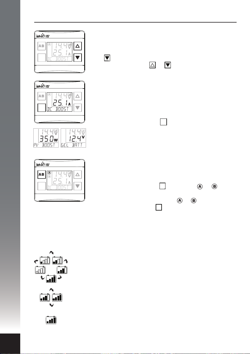
Toggle Alternate Screen
By default, the lower three digit character set will display
the current in Amps or, if solar power is in use, the
charging power in Watts (see g. i). The multi-function
character set will display the charging source and the
charge stage. Pressing the button momentarily will
OK
toggle an alternate screen to display the main battery
voltage on the lower character set and the battery type
on the multi-function set (see g. ii).
Toggle Between Two Charging Devices
If two Charging Devices are installed and connected to
a single display it is easy to toggle between both by
momentarily pressing the button. The or icon
AB
will indicate the status of the device being monitored. If
only one device is connected the or icons will not
appear and pressing the button will result in a system
AB
error message. The message will clear after a few seconds.
28
The Battery Icon is a useful quick reference tool used to indicate the charging
cycle status, when the Remote Display is in dual Voltage mode for example.
Boost/CC charging – All bars are continuously lling up in a cycle.
Absorption/CV charging – The rst three bars are lled and
steady and the last one is lling up.
Float/CV charging – All bars are lled and steady.
Page 31
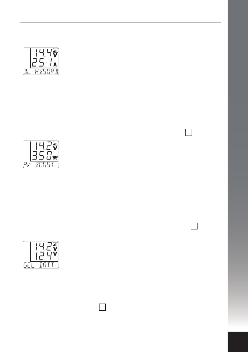
When battery to battery charging, the Remote Display will
indicate the following by default:
• Auxiliary Charging Voltage. This is displayed in Volts using
the upper character set.
• Auxiliary Charging Current. This is displayed in Amps using
the lower character set.
• Charging Cycle Status. This is indicated using the
multi-function character set and displayed as DC (Direct
Current) followed by the text BOOST, ABSORB, FLOAT,
BMS CC or BMS CV.
When solar to battery charging, the Remote Display will
indicate the following when activated with the button:
OK
• Auxiliary Charging Voltage. This is displayed in Volts using
the upper character set.
• Auxiliary Charging Power. This is displayed in Watts using
the lower character set.
OPERATION
• Charging Cycle Status. This is indicated using the
multi-function character set and displayed as PV
(Photovoltaic) followed by the text BOOST, ABSORB, FLOAT,
BMS CC or BMS CV.
In addition to the default information detailed above an
alternate screen can be accessed by pressing the button.
OK
The Remote Display will now indicate the following:
• Auxiliary Charging Voltage. This is displayed in Volts using
the upper character set.
• Main Battery Voltage. This is displayed in Volts using the
lower character set.
• Selected Battery Type. This is indicated using the
multi-function character set and displayed as SLA BATT,
AGM BATT, GEL BATT, LCA BATT or LFP BATT.
Pressing the button again will return the display to the
OK
default screen.
29
Page 32
OPERATION
Operator Convenience Settings
The Remote Display also allows certain changes to be made at any time or
‘on the y’. There are three options which can be congured for operator
convenience details as follows;
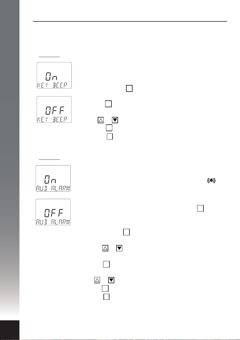
1) Option 1: The keypad beeper.
v. Press the button to exit (or wait 5 minutes for timer to
automatically exit).
2) Option 2: The audible alarm.
This option simply turns the keypad beeper, also known as
‘button clicks’, on or o. In default mode the keypad beeper
is enabled and can be disabled at any time.
i. Press and hold the button until an audible beep is heard
OK
and the text KEY BEEP appears.
ii. Press the button again and the word On will appear
OK
above the text line.
iii. Press or to toggle between On or OFF.
iv. Press the button to conrm your choice.
OK
AB
This option allows the operator to enable or disable the
audible alarm which operates in conjunction with the warning
system. By default the audible alarm is enabled and the
icon will be displayed on the main screen. The icon will
disappear when the audible alarm is disabled. In the event of a
warning condition the audible alarm can still be muted even if
it is enabled. In any warning condition, pressing the button
OK
serves as acknowledgment of the problem and automatically
mutes the audible alarm at the same time.
i. Press and hold the button until an audible beep is heard
OK
and the text KEY BEEP appears.
ii. Press the or to toggle the selection until the text
AUD ALARM appears.
iii. Press the button again and the word On will appear
OK
above the text line.
iv. Press or to toggle between On or OFF.
v. Press the button to conrm your choice.
vi. Press the button to exit.
OK
AB
30
Page 33
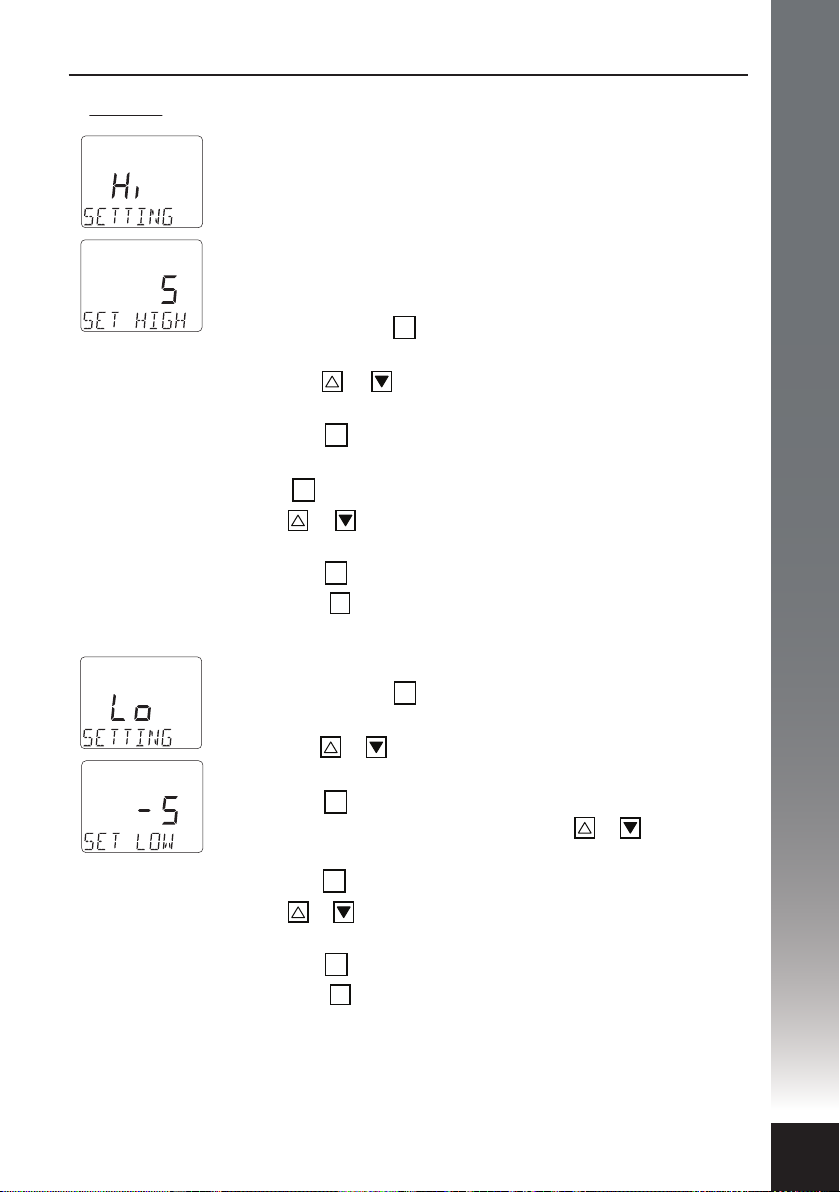
3) Option 3: The backlight brightness.
This option allows the operator to adjust the backlight
brightness for both high (Hi ) and low (Lo) settings to
enable the ‘one touch’ operation of both. Each setting allows
the brightness to be adjusted over 5 increments. In Hi
setting, the range is 0 through 5 with 5 being the maximum
and in Lo, 0 through -5 with -5 being the minimum.
To select the maximum backlight brightness:
i. Press and hold the button until an audible beep is
heard and the text KEY BEEP appears.
ii. Press the or to toggle the selection until the text
BACKLIGHT appears.
iii. Press the button again and the word Hi will appear
OK
above the text line SETTING.
iv. Press again and the text SET HIGH will appear.
OK
v. Press or to increase or decrease the backlight
brightness.
vi. Press the button to conrm your choice.
vii. Press the button to exit.
OK
AB
OPERATION
OK
To select the minimum backlight brightness:
i. Press and hold the button until an audible beep is
OK
heard and the text KEY BEEP appears.
ii. Press the or to toggle the selection until the text
BACKLIGHT appears.
iii. Press the button again and the word Hi will appear
OK
above the text line SETTING. Use the or to
toggle to text Lo.
iv. Press the button and the text SET LOW will appear.
OK
v. Press or to increase or decrease the backlight
brightness.
vi. Press the button to conrm your choice.
vii. Press the button to exit.
OK
AB
31
Page 34

OPERATION
System Status
The DCC Pro has a number of protection and monitoring mechanisms built in
to protect the product from application and installation issues as well as faults
that may occur in exceptional circumstances. To assist with troubleshooting any
problems that arise, the DCC Pro can indicate these issues in one of two ways,
via the Charging Device itself or on the Remote Display (if connected).
The Charging Device incorporates the LED Glow Ring, a multi-colour,
multi-function indicator which is illuminated according to the status of the
device. The Glow Ring will reect a range of conditions as a visual indication to
the operator/installer.
The Remote Display can visually and audibly alert the operator to the same
conditions as indicated by the LED Glow Ring with the advantage, as the name
indicates, of being located away from the Charging Device. These conditions
are detailed in the table below.
Glow Ring
Colour
White
Purple Intermittent Set-up
Blue Continuous Boost/CC
Blue/Green Alternate Absorption/CV
Green Continuous Float/CV
Yellow Intermittent
Orange Intermittent
Red Continuous
Red
Glow Ring
Frequency
Intermittent
(8 seconds)
Intermittent
S.O.S.
Status Remote Display
Stand by
High
Voltage
Over
Temperature
Device Issue
Reverse
Polarity
Indication
STAND BY*
TO CONFIG...
DC or pv BOOST
DC or pv BMS CC
DC or pv ABSorb
DC or pv FLOAT
DC or pv BMS CV
HIgh main
High AUX
high solr
OVER TEMP
check dvc
N/A
Condition Charger
State
Normal
Normal
Normal On
Normal On
Normal On
1
Alert
2
Alert
3
Alert
4
Alert
32
*Use the button to ‘awaken’ the display for temporary viewing.
OK
NOTE: For further information on alert conditions (1- 4) please refer to
troubleshooting guide on the following page.
Page 35
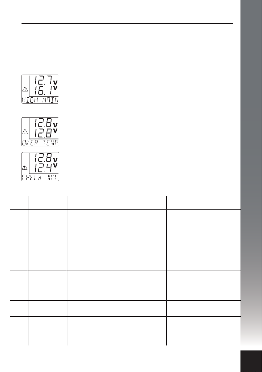
Alert Conditions
There are certain conditions that may arise in operation that could result in an
alert condition. In an alert condition the output of the Charging Device will be
automatically disabled and the alert symbol will be displayed (if the Remote
Display is on). A message indicating the cause of the condition will be displayed
on the multi-function character set.
If high Voltage is detected on Main, Auxiliary or Solar input
terminals, over Voltage protection will be enabled and will be
displayed as HIGH MAIN, HIGH AUX or HIGH SOLR.
Please see Alert1 condition in the table below for further
information.
In a situation where the Charging Device is subjected to extreme
temperatures for a prolonged period, thermal protection will be
activated and displayed as OVER TEMP. Please see Alert2
condition in the table below for further information.
In the event an internal input fuse ‘blows’ in the Charging Device
itself, the system is shut down and displayed as CHECK DVC.
Internal fuses protect the Charging Device from catastrophic
failure. Please see Alert³ condition in the table below for further
information.”
TROUBLESHOOTING
Alert Displayed Possible Reason Potential Solution
HIGH MAIN
HIGH AUX
1
HIGH SOLR
2
OVER TEMP
3
CHECK DVC The Charging Device has no output.
4
N/A
The vehicle’s charging system regulator
or ECU is faulty.
A battery charger of too high a Voltage
has been connected to the auxiliary
battery.
A solar panel with too high a Voltage
has been connected.
The Charging Device has overheated
due to high environmental temperature.
The Charging Device cooling ns are
obstructed.
The wiring has been reverse polarity
connected on all/any of the Charging
Device input or output terminals.
Check the vehicle’s charging
system Voltage.
Connect a battery charger
that meets the Voltage input
specications.
Connect a solar panel that
meets the Voltage input
specications.
Relocate the Charging Device
to a more suitable location.
Check the Charging Device
cooling ns for obstructions.
Return to vendor for testing.
Check and correct the
polarity immediately or
irreversable damage may
occur to the Charging Device.
33
Page 36
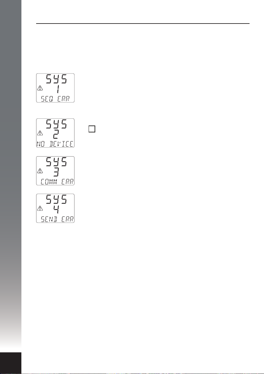
TROUBLESHOOTING
Error Conditions
In addition there are certain conditions which may result as a communication
issue between the Charging Device and Remote Display. These will be displayed
in the form of a System Error on the Remote Display in one of four ways, details
as follows:
SYS 1 – In the event an input error is made when
conguring the Charging Device (set-up) or if two Charging
Devices are connected and the user attempts to program
both simultaneously, a sequence error is detected and the
Remote Display will indicate SEQ ERR.
SYS 2 – If only one Charging Device is connected and the
AB
button is pressed (to toggle between Charging Devices)
a connectivity error is detected and the Remote Display will
indicate NO DEVICE. See note 1.
SYS 3 – If there is a data exchange issue between the
Charging Device and the Remote Display, a damaged Data
Cable for example, a communications error is detected and
the Remote Display will indicate COMM ERR. See note 1 & 2.
34
SYS 4 – In the event there is a transmission issue during the
conguration procedure and the Charging Device cannot be
programmed a corruption error is detected
and the Remote Display will indicate SEND ERR.
A transmission error is often caused by a fault with the Data
Cable or the connections. See note 2.
1. Please note that this error may also display when the Charging Device is in
the process of changing states/cycles at the precise moment the button is
pressed. Simply waiting a few seconds and trying the button again should result
in a successful reading.
2. If SYS 3 or 4 errors persist it is most likely the result of an issue with the Data
Cable. Disconnect and inspect both the Charging Device and Remote Display
plugs and sockets. Check there are no bent or broken pins in the Charging
Device socket. Check there are no broken wires at the Remote Display end.
If the above checks are conrmed as OK please contact your vendor for further
assistance.
Page 37

Frequently Asked Questions
Why am I unable to programme my DCC Pro after having installed it?
For safety reasons the DCC Pro cannot be programmed while the auxiliary
battery is connected. Disconnect the auxiliary battery, programme the DCC Pro
and re-connect. Please refer to step by step installation instructions on pages
19–24 for clarication.
Why can’t I enter the programming mode after pressing the Remote Display
OK
button?
Press and hold the button until you hear the audible beep. If you release the
button before, you will initiate a system error. Wait 1 minute before pressing the
OK
button again.
Why do I get a system error when I try to re-programme the DCC Pro?
Disconnect both batteries then re-connect the main battery only. Press and
hold the button until you hear the audible beep. Follow installation steps 7
OK
through 12 in the manual. Leave for 1 minute. Start engine and the display will
show auxiliary battery Voltage and current.
Should I programme the DCC Pro to operate in ignition or Voltage mode?
This primarily depends on where the Charging Device itself will be installed. If it
is located in the vehicle then ignition mode is recommended. If it is located in a
caravan/camper it may not be viable to run a control wire and therefore Voltage
mode is the best option. See page 7 for comprehensive details.
OK
TROUBLESHOOTING
When programming for ignition mode should I choose normal or low setting?
For vehicles with an ECU controlled charging system you should select the ‘low’
setting. For vehicles with a conventional charging system you should select
‘normal’. If you are unsure you will need to contact your vehicle dealership to
conrm your charging system specics.
Why do I get a system error when I press the Remote Display button?
OK
Once the unit is programmed (after installation step 12) you need to connect
the auxiliary battery to commence normal operation.
Why does my Remote Display stay on after I turn the engine o?
In voltage control mode the device is activated and de-activated based on the
main (starting) battery Voltage. If the Remote Display is still on, it is because the
main battery Voltage has not yet dropped below 12.6V for a given time.
35
Page 38

SPECIFICATIONS
Input Voltage
Main
Solar
Solar Power Unrestricted (system limited to 25 Amps)
Continuous Rating 25 Amps@50°C (de-rate from 50°C to 85°C)
Current Draw
Charging Device
Remote Display
9 – 16 VDC
18 – 28 VOC (open circuit Voltage – no load)
In stand by: Including LED indicator <10mA
At full load: Up to 35 Amps
With backlight off: 10mA max
With backlight on: 45mA max
Output Voltage
Standard Lead Acid
Absorbed Glass Mat
Gelified Electrolyte
Lead Calcium
LiFePO4 BMS 14.6 VDC
Electrical Protection Over temperature disconnect – auto re-connect
Environmental Protection
Charging Device
Remote Display
Operating Temperature -20°C to +85°C
Operating Humidity Up to 100% (non-condensing)
Charging Device Materials
Heatsink
Blue Plastics
Black Plastics
Transparent Plastics
Remote Display Materials
Dark Grey Plastics
Transparent Plastics
Termination Tin plated brass terminals, 304SS fasteners
Conformity AS/NZS CISPR 11:2004 for EMC
Dimensions
Charging Device
Remote Display
Weight
Charging Device
Remote Display
Boost/CC Absorption/CV
14.5 VDC
14.7 VDC
14.3 VDC
14.9 VDC
Voltage values subject to tolerance ± 0.1V
Under Voltage shutdown – auto re-start
High Voltage disconnect – auto re-connect
Reverse polarity protection on all terminals
IP67 (internal components only)
IP40 (not dust or water resistant)
E-Coated ADC-3 die cast aluminium
10% glass reinforced PC/ABS alloy
15% glass reinforced PBT
Temperature resistant PMMA
Temperature resistant PC/ABS alloy
Temperature resistant PMMA
112 x 112 x 75mm (including terminal cover)
60 x 36 x 59mm (including mounting bracket)
690 grams
55 grams
14.4 VDC
14.6 VDC
14.2 VDC
14.8 VDC
Float/CV
13.4 VDC
13.6 VDC
13.5 VDC
13.8 VDC
14.4 VDC
36
Page 39
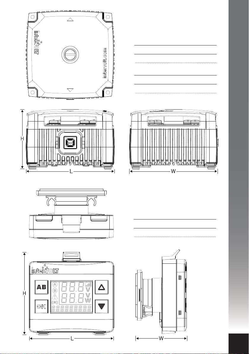
DCC Pro Charging Device
Length Width Height
112mm 112mm 75mm
Footprint Mounting Centres
95mm x 95mm
DIMENSIONS
OK
DCC Pro Remote Display
Length Width Height
60mm 36mm 59mm
37
Page 40

APPENDIX
Fundamentals in Detail
CHARGING FUNCTIONS
Soft start: This function is the initial phase of the boost/CC stage cycle. In soft
start the current is allowed to build gradually, eectively controlling the high
inrush current normally experienced at ‘switch on’. Controlling the inrush current
reduces the risk of further damage if the battery is unserviceable and prevents
potential issues with any equipment that may be powered from the battery at the
time. Many manufacturers refer to a soft starting feature as an additional stage. In
reality however it is simply another process used for controlling the boost/CC cycle
to properly manage the auxiliary battery.
Thermal control: This function is enabled when the temperature of the Charging
Device rises above a pre-set limit. When the environmental temperature exceeds
50°C and the Charging Device is under full load (25 Amps), thermal control is
initiated. When thermal control is activated it enters a pre-programmed control
mode allowing current output to continue subject to temperature rise. As the
temperature increases the current is reduced proportionally over time so that the
charging process can still be maximised for the hottest of conditions.
Input Voltage control: This function is incorporated to compensate for Voltage
drop caused by undersize cable, poor connections, improper termination, etc. by
comparing the input Voltage at the main battery terminal with the Voltage at the
Charging Device itself. It does this by momentarily disconnecting the auxiliary
battery, thereby removing the load. At this time it measures the Voltage without
load to determine the true Voltage. It will then establish if the true Voltage is high
enough to continue charging or to implement low Voltage shut down.
38
Override Timer Control: This function utilises an inbuilt timer which allows the
system to re-instate the last charging stage if the main charging source is
interrupted for any reason within a 30 minute period. For example, if the system
was in boost/CC and a fuel stop was required within 15 minutes of setting out,
upon re-starting the vehicle, the system will remember and re-instate the
boost/CC stage of the charging cycle. If the system was in oat/CV stage at the
time and the voltage drops over the 30 minute period, the boost/CC stage may be
initiated.
CONTROL MODES
Voltage control mode: In Voltage control mode the charging control process is
automatic and is based on Voltage sensed at the input and output terminals of the
Charging Device. When the main battery Voltage rises above 13.0V the system will
commence operation. The charging cycle is determined by the auxiliary battery
Voltage and may enter boost/CC or oat/CV stage depending on this Voltage.
Conversely, if the Voltage of the main battery drops below 12.6V the system will
revert to stand by. If solar power is actively available, PV stage may be initiated.
Page 41

Ignition control mode: In ignition control mode the system is controlled
dierently because the operator is eectively directing the function of the
device when they turn the key on or o. In this mode the DCC Pro has two
optional settings. These settings allow the DCC Pro to be used in traditional
vehicles with conventional charging methods or the new ECU controlled
systems used in modern design. The NORMAL setting is provided for the former
and the LOW for the latter. In ignition mode the start-up Voltage is the same
value in both NORMAL and LOW settings and is set to 12.8V (remember this is
the Voltage level of the main battery). In order to conserve power, the DCC Pro
will NOT commence charging, even with the ignition ON if the main battery has
a Voltage level below 12.8V. The dierence between the settings is the low
Voltage cut-out limit. These limits are set as follows:
1. NORMAL: 12.0VDC
2. LOW: 11.5VDC
If the main battery falls below these levels the DCC Pro will stop charging
immediately in order to protect it from further discharge.
CHARGING METHODS
Boost/CC: The boost/CC stage (also known as bulk charge) is the stage when
the Charging Device is operating in constant current mode. In CC mode is
producing the heavy current required to re-charge a depleted battery as quickly
as possible. The boost/CC Voltage is determined by the battery type selected in
the initial set-up phase. The boost/CC stage is controlled by an algorithm of
time vs Voltage to ensure that the battery is charged optimally under the given
conditions. In boost/CC stage the charger will produce up to 25 Amps
(maximum) subject to the aforementioned conditions. When the Charging
Device is powered up and the auxiliary battery measures 12.6V or below the
boost/CC stage is then initialised. At this point the ‘soft start’ function is also
enabled (see page 38 for detailed information) and current ows. The boost/CC
stage is completed or terminated under the following conditions:
APPENDIX
• when the auxiliary battery reaches terminal Voltage
(pre-determined by the battery type selected) ; or
• the maximum boost/CC time has expired before the
battery has reached terminal Voltage.
In the instance where the boost/CC time has expired before reaching terminal
Voltage, the charging process will skip the next (absorption/CV stage) and
progress directly to the nal (oat) stage. Generally this occurs when the
auxiliary battery is damaged or no longer serviceable.
Continued...
39
Page 42

APPENDIX
In order to prevent further damage due to overcharging, the DCC Pro is
programmed for the safest option which is to reduce the Voltage by switching
out of constant current mode into oat stage. There is also the possibility that a
heavy load permanently connected to the auxiliary battery is responsible for the
charging cycle to time out in boost/CC stage before terminal Voltage is achieved.
If this is the case the DCC will continue to monitor the Voltage and if the Voltage
drops below 12.0V again (during the two minute check period), the boost/CC
stage will re-initiate and the whole process will start over.
Absorption/CV: The absorption/CV stage, the next step in the charging cycle,
is initialised when the boost/CC stage is completed. In absorption/CV stage the
charger is operating in Constant Voltage (CV) mode and is also time limited. The
time is calculated from the boost/CC cycle and is based on a maximum of four
times the actual boost/CC time (subject to the battery type selected). As with the
boost/CC stage the current is limited to 25 Amps. The absorption/CV stage is
completed or terminated under the following conditions:
• the programmed time cycle has nished
(pre-determined by the battery type selected) ; or
• the charge current is reduced below 4 Amps
(approximately 15% of maximum charge current).
40
Float/CV: The nal process in the charging cycle is the oat stage. In oat stage
the charger is operating in Constant Voltage (CV) mode. The oat Voltage is
determined by the battery type selected in the initial set-up phase. The oat
stage is programmed to maintain and monitor the battery indenitely and as
such, allows the auxiliary battery to be connected permanently without any risk
of overcharging. As with the boost/CC and absorption/CV stage the current is
limited to 25 Amps.
It is important to note that solar power can only be utilised if it is required.
In other words, if the batteries are fully charged and there is no load on the
auxiliary battery, the power is therefore unusable. Accordingly the charging
power displayed on the Remote Display may read zero Watts so do not be
alarmed to see this result under these conditions. The solar charging method
operates in two dierent ways depending on the control mode selected - Voltage
or ignition. These charging control modes are explained on page 7.
Page 43

interVOLT products are warranted for a period of 24 months against faulty materials
and/or workmanship from date of purchase by the end user subject to proof of
purchase. In the event proof of purchase is not provided, and at the discretion of the
manufacturer, the warranty shall be 24 months from manufacturer’s date of sale to
the merchant from whom the product was purchased. Intervolt’s 24 month warranty
is subject to the following terms and conditions:
The goods must be installed and operated in accordance with the manufacturer’s
recommendations and instructions set out within this booklet.
In the event of a claim the goods are to be returned to the original point of purchase
with a copy of the merchant invoice or the relevant merchant invoice number.
In the event of a claim any associated expenses including diagnosis, removal, and/or
installation of the goods is the responsibility of the client including any freight costs.
The warranty shall be void where the goods have been used for a purpose for which
they are not intended, or altered in any way that is detrimental, or opened or
tampered with by an unauthorised party, or damaged by mechanical abuse, or
contaminated by water or other substances (other than IP rated products), or
damaged by incorrect application.
Save and except for the express warranty set out above and to the maximum extent
permitted by law, all conditions and warranties which may at any time be implied by
the common law, Trade Practices Act, Fair Trading Act or any other State or Federal
Act are excluded. To the extent that these cannot be excluded and where the law
permits, the manufacturer in respect of any such condition or warranty shall be
limited at their option to the repair or the replacement of the goods or the supply of
equivalent goods or refunding the cost of the goods.
WARRANTY POLICY
41
Page 44

e
n
d
w
&
O
n
a
i
l
a
r
t
s
u
A
O
p
e
r
a
t
e
d
b
l
e
a
l
P
c
a
y
c
e
R
%
0
0
1
c
k
a
g
i
n
g
C
r
o
e
m
w
o
P
r
a
l
o
S
p
a
t
i
b
l
e
Manufactured by Intervolt Pty Ltd
interVOLT is a registered trademark of Amelec Australia Pty Ltd in Australia and various other countries
including the UK and USA and as such is protected by the relevant laws of the country of registration.
© 2019. All rights reserved. The entire contents of this instruction manual shall remain the property of
Amelec Australia Pty Ltd and should not be reproduced without written permission.
Manual No. DCCAUTG1 R2-0
 Loading...