

InterVac IVD660-H Installation And Operating Manual

THE COMPACT CENTRAL VACUUM SPECIALIST
INSTALLATION and OPERATING MANUAL
RECORD THIS INFORMATION FOR
FUTURE REFERENCES
MODEL NUMBER _______________________
DATE OF PURCHASE ___________________
PLACE OF PURCHASE__________________
Manual # M13 date: 1-6-17
rev.:
TYPE: 120 VOLT IVD660-F
IVD660-H
IN-WALL INSTALLATION
SURFACE MOUNTED
IF YOU SHOULD HAVE ANY QUESTIONS OR EXPERIENCE A PROBLEM WITH YOUR INTERVAC
PRODUCT,
This manual must be read and understood before installation, adjustment, service or maintenance is performed.
This unit should be installed by a qualified technician. Modification of this product can be extremely hazardous
and could result in personal injury or property damage.
Phone 772-463-1400 • USA & Canada toll free 888-499-1925
www. .com •
DO NOT RETURN THIS PRODUCT TO THE STORE OR DEALER
PLEASE CALL US DIRECT 1-888-499-1925
WARNING:
InterVac Design Corp., Palm City, FL 34990
2939 SW 42nd Avenue
intervacdesign e-mail: orders@intervacdesign.com
Owner read carefully.
Instructions must stay with unit.
66XF
IMPORTANT SAFETY INSTRUCTIONS
Polarizati on Instructions for models with 120volt cord only.
These appliances have a polarized plug (one blade is wider than the other). This plug will fit in a
polarized outlet only one way. If the plug does not fit fully in the outlet, reverse the plug. If it still does not
fit, contact a qualified electrician to install the proper outlet. Do not change the plug in any way.
When using an electrical vacuum cleaner, basic precautions should always be followed including the following:
Read all instructionscarefully before using this vacuum cleaner.
WARNING: TO REDUCE THE RISK
OF FIRE, ELECTRIC SHOCK, OR INJURY:
11.
1.
Unplug from electrical outlet when not in use andbefore
servicing.
2.
Do not useon wet surfaces.
3.
Never operate this vacuum cleaner without adust bag and filters
in place.
4.
Close attention isnecessary when used by or near children.Do
not allow unit to be used as a toy.
5.
Use only for intended use as described inthis manual. Use only
the manufacturer's recommended attachments and dust bag.
6.
Do not usewith damaged cord or plug. Ifappliance is notworking
as it should, has been dropped, damaged, leftoutdoors, or fellinto
water, return the vacuum cleaner to InterVac or an authorized
service dealer for examination and repair.
7.
Do not put any object intoopenings. Do not use with any openings
blocked; keep free of dust, lint, hair and any other material that
may reduce air flow. If the secondary filter becomes dirty,
rinse in warm water or replace with a new filter. Filter should be
completely dry before using.
8.
Never drop or insert any object into any opening.
9.
Turn off all controls before unplugging.
10.
Do not pull or carry by cord, do not use cord as ahandle, do not
close adoor on the cord,or pull cord around sharp edges or
corners. Do not runover cord. Keep cord away from
heated surfaces.
Do not unplug by pulling on cord. To unplug, grasp the plug, not
the cord.
12.
Keep hair, loose clothing, fingers, and all parts of body away
from any openings and all moving parts.
13.
Do not pick up anything that is burning or smoking, such as
cigarettes, matches, or hot ashes.
14.
Use extra caution when cleaning on stairs.
15.
Do not handle plug or appliance with wet hands.
16.
Do not pick up flammable or combustible liquids such as
gasoline, or use in areas where they may be present.
17.
Do not place objects against the vacuum cleaner. Keep area
clear.
18.
Do not step on the hose or pull the hose forcibly.
19.
Do not pick up large objects such as waste paper or cloth,
which may clog the hose.
20.
Do not install this vacuum cleaner in an area exposed to high
temperatures.
21.
Install this vacuum cleaner in a dry place.
22.
Do not attempt to service the vacuum cleaner. Unit is sealed
and cannot be opened without damage to the unit. For service,
call your local authorized service dealer, or InterVac Design's
Customer Care Center.
SAVE THESE INSTRUCTIONS
FOR HOUSEHOLD USE
2
Specification: 120 Volt, 12.5 Amp 50/60Hz, Weight 8 lb
Parts List:
Model IVD660-F MODEL IVD660-H
Mounting frame for 2x4 wood studs, 16” on center Steel vacuum hanger + screws
6 screws for installing frame Left and right side panel
Slider, pipe connetion
Included with both models: 1 reducer fitting for connecting to in-wall piping system
2 high filtration dust bags Y20
Model 660-H new construction installation
Surface mounted installation with attached.Power Cord
To remove side panels, the 4 screws inside the vacuum chamberloosen
1) Remove the door from the vacuum, by pulling from the top on the curved bracket.
inside you will find:
1 black flanged fitting with 4 screws
1 white reducer
. 1 pipe coupling
1 pipe slider with 2 o-rings inside
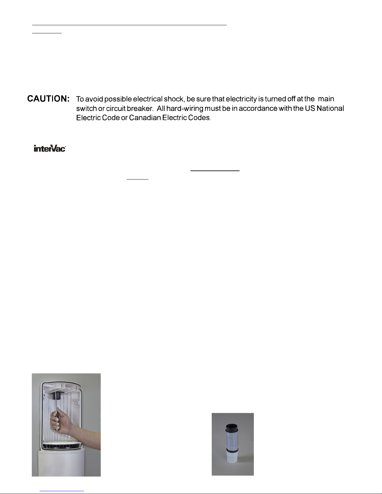
2) Take the black flanged fitting and insert the o-ring side of the fitting first, into the hole inside
the top of vacuum chamber and secure with the 4 screws supplied. See pic. below.
Generously apply a lubricant, like Vaseline, to the o-ring on the black fitting.
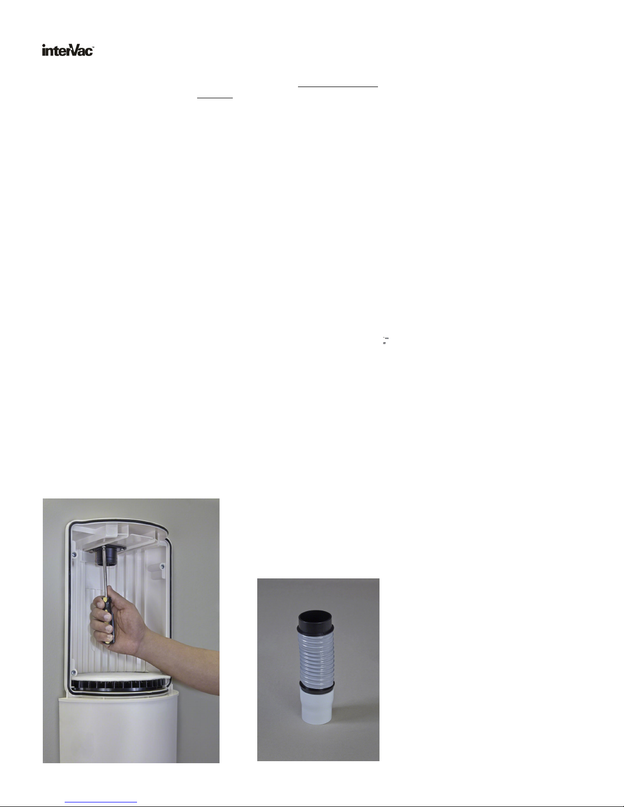
3) Find the reducer and the pipe coupling and glue together.
Position and install mounting bracket for the vacuum at a comfortable height on the wall.
4)
Hang the vacuum over the mounting bracket. Watch that the yellow, low voltage wire, are in their groove.
5)
The 120 volt power receptacle should be within 4 feet.
6) Take the glued reducer/coupling and place over the o-ring fitting on top of the vacuum.
Now bring the new connecting pipe from the ceiling or the wall straight in line with the reducer/coupling.
You need ½” space between the pipe and the coupling. Deburr the end of the pipe after cutting.
Align as perfect as possible.
7) Now generously lubricate the 2 o-rings in the slider with Vaseline. Push the slider onto the pipe coming
from the ceiling. The o-ring closest to one end of the slider should point down.
Align the pipe with the coupling and push slider onto the coupling.
8) Attach the cord to the receptacle.
Lift the valve cover on the door, to test the vacuum with the switch on the lower right
side.
Attaching black flanged
fitting
3
Please Note:
Flexible hose connection
also available, instead of
Slider connection.
3
Model 660-H vacuum replacement installation
Surface mounted installation with attachedPower Cord
To remove side panels, the 4 screws inside the vacuum chamberloosen
1) Remove the door from the vacuum, by pulling from the top on the curved bracket.
inside you will find:
1 black flanged fitting with 4 screws
1 white reducer
. 1 pipe coupling
1 pipe connect slider with 2 o-rings inside
2) Take the black flanged fitting and insert the o-ring side of the fitting first, into the hole inside
the top of vacuum chamber and secure with the 4 screws supplied. See pic. below.
Generously apply a lubricant, like Vaseline, to the o-ring on the black fitting.
3) Find the reducer and the pipe coupling and glue together.
4) Locate pipe coming out of the ceiling or the wall, and the receptacle in the wall from the old vacuum.
5) Position the vacuum at a comfortable height on the wall as close as possible in line with the
pipe from the ceiling. If necessary use 2 x 45 degree elbows to align ceiling pipe.
You also might have to extend the pipe.
6) Take the glued reducer/coupling and place over the o-ring fitting on top of the vacuum.
7) Now push the slider onto the pipe from the ceiling. The o-ring closest to one end should point down.
8) Slide the vacuum up the wall until there is about 1/2” space between the ceiling pipe and the
reducer/coupling fitting. With a pencil mark the top of the vacuum.
9) Install the mounting bracket to the wall, in center line with the pipe from the ceiling and measure 2-1/16”
from pencil mark downwards. See drawing next page.
10) See to it, that the 2 yellow low voltage wires, in the back of the vacuum are nicely tucked into the groove.
hang the vacuum on the mounting bracket, and check if the electric cord reaches the receptacle.
11) Now push the slider down onto the reducer/coupling.
Connect the yellow wires to the wires from the installed pipe system.
Install the electrical plug into the receptacle.
Model 660-H vacuum replacement installation
Surface mounted installation with a ttachedPower Cord
4
Lift the valve cover on the door, to test the vacuum with the switch on the lower right
side.
Attaching black flanged
fitting
Please Note:
Flexible hose connection
also available, instead of
Slider connection.
4
 Loading...