

RECORD THIS INFORMATION
FOR FUTURE REFERENCES
MODEL:________________
THE COMPACT CENTRAL VACUUM SPECIALIST
DATE PURCHASED:_______
PLACE PURCHASED_
Manual # M10
Revision Date:11-21- 2018
INSTALLATION AND OPERATING MANUAL
120 VOLT POWER UNITS
MODEL CS-6 for Power Management
MODEL CS-8 Power Cord or Hardwired
MODEL CS-RM with Power Cord
_
________
VacPort
VacPort
Model CS-6 + CS-8
Vacuum valve
PLEASE NOTE:
CS8 and CS6
The have single opening in the dust bag
CS-RM
The has double opening in the dust bag
IF YOU SHOULD HAVE ANY QUESTIONS OR EXPERIENCE A PROBLEM WITH YOUR INTERVAC
PRODUCT, DO NOT RETURN THIS PRODUCT TO THE STORE OR DEALER, PLEASE CALL OUR
SERVICE DEPARTMENT AT: 1-888-499-1925, WE ARE HERE TO HELP.
WARNING:
Owner read carefully.
Model CS-RM
Model CS8-RM
This manual must be read and understood before installation, adjustment,
service or maintenance is performed. This unit should be installed by a
qualified technician.
InterVac Design Corp. ,
2939 SW 42nd Ave. Palm City, Fl. 34990
1-888-499-1925 www.intervacdesign.com •
e-mail: intervac@intervacdesign.com
66XF
IMPORTANT SAFETY INSTRUCTIONS
POLARIZATION INSTRUCTIONS FOR MODELS CS-8 AND CS-RM WITH POWER.
These have a polarized plug (one blade wider than the other). This plug will fit in a
Polarized outlet only one way. If the plug does not fit fully in the outlet, reverse the plug.
If it does not fit, contact a qualified electrician to install the proper outlet. Do not change
the plug in any way!
When using an electrical vacuum cleaner, basic precautions should always
be followed including the following: Read all instructions carefully before
WARNING: TO REDUCE THE RISK OF
FIRE, ELECTRIC SHOCK, OR INJURY:
1.
Do not leave appliance when plugged in. Unplug from an
electrical outlet when not in use and before servicing.
2.
Do not use outdoors or on wet surfaces.
3.
Never operate this vacuum cleaner without a dust bag and filters
in place.
4.
Close attention is necessary when used by or near children.Do
not allow unit to be used as a toy.
5.
Use only for intended use as described in this manual. Use only
the manufacturer's recommended attac hments and dust bag.
6.
Do not use with damaged cord or plug. If appliance is not working
as it should, has been dropped, damaged, left outdoor s, or
fell into water, return the vacuum cleaner to InterVac or an
authorized service dealer for examination and repair.
7.
Do not put any object into openings. Do not use with any openings
blocked; keep free of dust, lint, hair and any other material that
may reduce air flow. When the secondary filter becomes dirty,
rinse in warm water or replace with a new filter. Filter should be
completely dry before using.
8.
Never drop or insert any object into any opening.
9.
Turn off all controls before unplugging.
10.
Do not pull or carry by cord, do not use cord as a handle, do not
close a door on the cord, or pull cord around sharp edges or
corners. Do not run appliance over cord. Keep cord away from
heated surfaces.
DO NOT USE WITH EXTENSION CORD!
using this vacuum cleaner.
11. .
Do not unplug by pulling on cord. To unplug, grasp the plug
not the cord.
12.
Keep hair, loose clothing, fingers, and all parts of body away
from any openings and all moving parts.
13.
Do not pick up anything that is burning or smoking, such as
cigarettes, matches, or hot ashes.
14.
Use extra caution when cleaning on stairs.
15.
Do not handle plug or appliance with wet hands.
16.
Do not pick up flammable or combustible liquids such as
gasoline, or use in areas where they may be present.
17.
Do not place objects against the vacuum cleaner. Keep area
clear.
18.
Do not step on the hose or pull the hose forcibly.
19.
Do not pick up large objects such as waste paper or cloth,
which may clog the hose.
20.
Do not install this vacuum cleaner in an area exposed to high
temperatures.
21.
Install this vacuum cleaner in a dry place.
22.
Do not attempt to service the vacuum cleaner. Unit is sealed
and can not be opened without damage to the unit. For
service, call your local authorized service dealer, or
InterVac Design's Customer Care Center.
SAVE THESE INSTRUCTIONS
for Household and R/V use
2
Specification:
CS-6 and CS-8 120 Volt, 9.5 Amp 60Hz, Weight 5.5 lb
CS-RM 120 Volt, 10 Amp 60Hz high efficiency motor, Weight 5.6 lb
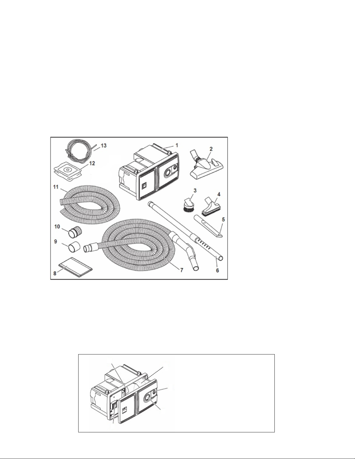
Parts List:
Vacuum Cleaner with screws and clamps
Vacuum tool kit: various
Read the Safety Instruction on the yellow label on the housing!
CAUTION: DISCONNECT POWER BEFORE ATTEMPTING TO INSTALL THIS UNIT.
CHECK FOR ANY OBSTRUCTIONS BEHIND THE MOUNTING SURFACE
Please Note:
Some of our CS
models do not have
the complete vacuum
tool accessory kit as
pictured on the left.
Part:
1) power unit
2) floor tool
3) dust brush
4) upholstery tool
5) crevice tool
6) telescoping wand
4
6
1
7) 20, 30 or 40 foot vacuum hose
depending on model
8) inlet valve for CS-RM only
9) pipe to pipe coupling, CS-RM only
10) pipe to flex-hose coupling, CS-RM
11) 2” dia. Black Flex-hose, CS-RM only
12) dust bags (2)
13) 6’ low voltage wire, for CS-RM only
5
1) on-off switch
2) sliding hole cover
3
3) lock-slider
4) motor filter
5) dust bag
7
2
6) vacuum housing
7) vacuum front panel
3
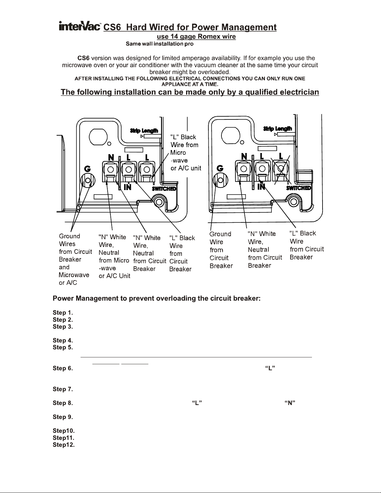
cedure as on page 5 and 6
For Power Management CS-6 only Hard Wiring model CS-8 or CSRM
Turn off the breaker to the area you will install the unit.
Find the power cable connecting the Microwave Oven to the Circuit Breaker.
Disconnect the exiting cable at the Microwave Oven. Reroute the cable to the Vacuum
cleaner installation.
In the back of the vacuum find the wire connections.
Strip all 3 wires by about 5/8”.
Tip: leave a loop in the wires from the vacuum to the wall where the cables are
securely attached.
From the Microwave (or other appliance) connect the Black wire to (line)(switched),
the White wire into (neutral) and connect the Ground wire under the washer screw
head to .
From the Circuit Breaker run a new 14 or 12 gage Romex cable to the back of the
vacuum.
Strip the 3 wires and attach the Black to , the White wire into the other (neutral)
and the GROUND wire to the other connection.
Attach the wire cover (supplied) over the connections by guiding the wires through the
opening at the bottom of the cover and screw cover into place.
On the front side of the vacuum, toggle the switch to “SOURCE”.
Switch-on the circuit breaker and check if the other appliance is operating.
Now toggle the switch on the Vacuum to “VAC”.
The other appliance will stop operating and the Central Vacuum is ready for use.
“G”
“N”
“G”
4

CS-8 Installation Instruction
POWER UNIT
3/8
The central vacuum should be mounted so that power supply cord can be plugged directly
into a electrical outlet.
Choose a place that is centrally located to maximize the reach with the vacuum hose.
The minimum wall thickness is 3/8” the maximum is 1”.
The cut-out in the wall is 11“ wide X 6” high and requires 6” depth.
Very important:
Option 1: 3”
Option 2: 2”
Step A.
Step B. .
Step C.
Step D.
Cut a hole in the cabinet a minimum , attach a louver to cover the hole.
Use our part #AS-61 exhaust fitting with a diameter flex-hose to guide
the warm air to the outside, or to where ever you prefer. See page 12 options.
Tape the paper template against the surface at a comfortable operating height
With a skill saw cut along the dotted line of the paper template
Slide the unit, power cord in first, into the opening and secure by tightening
the four attached screws behind the front panel with the “clamps”.
Do not over-tighten.
Check to be sure dust bag and motor filter are in place.
If you installed the vacuum in a very small cabinet you must
make provisions to exhaust the air from the vacuum out of the cabinet.
5

7
FIG 7.
With a Phillip head screw
driver adjust the distance
between the clamp and the
vacuum frame so the clamp
reaches behind the frame.
8
8
FIG 8.
Slide the vacuum with the
cord into the opening.
You might have to hold the
2 lower clamps up.
9
FIG 9.
Now tighten the 4 screws
the clamps will press
against the back of the
wall, Do not over tighten.
When removing vacuum
only unscrew 2 or 3
revolutions.
6

CS-RM Installation Instruction
SEE PAGE 5 and 6 FOR THE POWER UNIT INSTALLATION
1) Inside the vacuum chamber you will find the flanged pipe with 4 screws.
Attach the black flanged pipe into the back hole of the power unit.
2) Install the vacuum valve about 3 to 4 feet from the vacuum. (the 2”dia.
flex-hose is 4 feet long).
3) with a circular saw, see above on the right and below, cut a 2-1/2” hole,
with a jig saw open the hole so that the vacuum valve is flush with the wall.
4) then route the 2” flex-hose form the vacuum to the valve.
Route the supplied (low voltage, 24v.) white wire (the wire has 2 small
leads) along the flex-hose to the back of the vacuum to the 2 yellow pigtails.
IMPORTANT
: leave 3” of slack at the connections.
Do not
remove the 2 screws at the valve completely
unscrew just enough to get the wires under the screw heads.
5) connect the yellow wires with wire nuts outside the housing.
6) secure the wires.
A) Pipe coupling to be press-fit to
flanged pipe.#P-30
B) Threaded pipe couplings, #D-900
C) Flex-hose, 2“ diameter, 4 feet, #X-640
D) Flanged pipe coupling attached to
vacuum housing. #D-920
E) Vacuum valve with reducer attached.#E-40
NOTE for circle; screw the threaded
pipe coupling counter clockwise into
the flex-hose and press-fit the other
side into the connectors.
E
CS-RM
A
B
C
B
D
7

VARIOUS VALVE CONNECTION for CSRM Model
AS40-E
valve/reducer
D900 Threaded Hose
Coupling, 2 required
AS40-E, black
valve/reducer
D900 Threaded Hose Coupling
4 required
A900-E VacPort, LED, black
Coupling glued to Vacport
pipe
P30, Pipe to
Pipe Coupling
X640, 2" dia. flex hose
# AF-01
CS-RM
P30 pipe coupling
D920 flanged fitting,
supplied with vacuum
P40, 45° "T"
CS-RM
# AF-15
X640, 2" dia. flex hose
AS40-E, black
valve/reducer
D900 threaded Hose
Coupling, 6 required
A900-E VacPort, LED, black
P30 Pipe to
Pipe Coupling
attached
Please Note:
Counter clockwise, screw threaded coupling
D900 into flex-hose. Press-fit the other side
or: use Elbow P21
with the coupling P30
into the fittings with a slight twist. Do not glue.
P41, Sweep "T"
OR
P40, 45° "T"
# AF-10 with P40, with 45 “T”
# AF-20 with P41, with sweep “T”
X640 FLEX-HOSE ORDERED SEPARATE
CS-RM
8

#19 Model CS-RM; handling and disposing of the double sided dust bag.
#20 Model CS-RM; inserting the dust bag, see also page 10 picture 1,2 + 3.
#21 All Models; inserting the front panel into the collar of the dust bag.
#10 All Models; attach the front panel in an angle on the left side first.
DO NOT USE FORCE! Then push slider lock to the right, see arrow.
#23 All Models; removing the motor filter
Also see pictures on the next 2 pages
9

CAUTION:
DO NOT PICK UP LIQUIDS, LIT CIGARETTES, HOT ASHES,
RAZOR BLADES, NEEDLES, PINS OR OTHER SHARP OBJECTS!
h
10

Attaching Front Panel and Dust Bag to Vacuum
Picture D
Insert Motor filter first,
slide dust bag
chamber.
into vacuum
then
Picture E Picture F
Slide front panel with left
side into the vacuum
frame.
Watch out that bag does
not get clamped between
front panel and frame!
Snap front panel down into
the frame and push the
latch to the right to lock.
11

Options:
and is restarted, see page 10.
Part # AS-61, Exhausting the warm air from the vacuum outside the
cabinet when vacuum is to be installed in a very confined space.
AS-61 consists of a funnel which snaps into the back of the vacuum,
2.5 feet of flex-hose X640 and a flanged spigot.
Attach flex-hose to funnel and spigot with PVC glue or hose clamps.
Part #C065. Set of mounting brackets for all CS Models. If you do
not like to install the CS models in a wall, you can mount the
vacuum on a horizontal surface, upside down or against a vertical
wall.
12
 Loading...