

InterVac A900, A910 Installation And Operating Manual
By
RECORD THIS INFORMATION FOR
FUTURE REFERENCES
MODEL NUMBER_______________________
DATE OF PURCHASE ___________________
PLACE OF PURCHASE__________________
Manual # M010 Date: 01-2015
INSTALLATION AND OPERATING MANUAL
MODEL A900 with LED
MODEL A910 without LED
IF YOU SHOULD HAVE ANY QUESTIONS OR EXPERIENCE A PROBLEM WITH YOUR
DO NOT RETURN THIS PRODUCT TO THE STORE OR DEALER
PLEASE CALL OUR CUSTOMER SERVICE DEPT. AT: 1-888-499-1925
This unit should be installed by a qualified technician.
2939 SW 42nd Avenue, Palm City, FL 34990
Phone 772-463-1400 • USA & Canada toll free 888-499-1925
www. .com •
intervacdesign e-mail: intervac@intervacdesign.com
INTERVAC PRODUCT,
InterVac Design Corp.
ELECTRICAL REQUIREMENTS:
The low voltage Control Wires from your Central Vacuum Cleaner
have mostly an output of 24volt AC.
: some Central Vacuums have 24volt DC output. If your vacuum
Note
does not start --- just reverse the 2 wires at the wire nuts.
(reverse the polarity).
Installation: into a kitchen cabinet kick-board or room base
board flush with the floor.
IMPORTANT: DISCONNECT THE POWER TO THE CENTRAL
VACUUM BEFORE INSTALLING
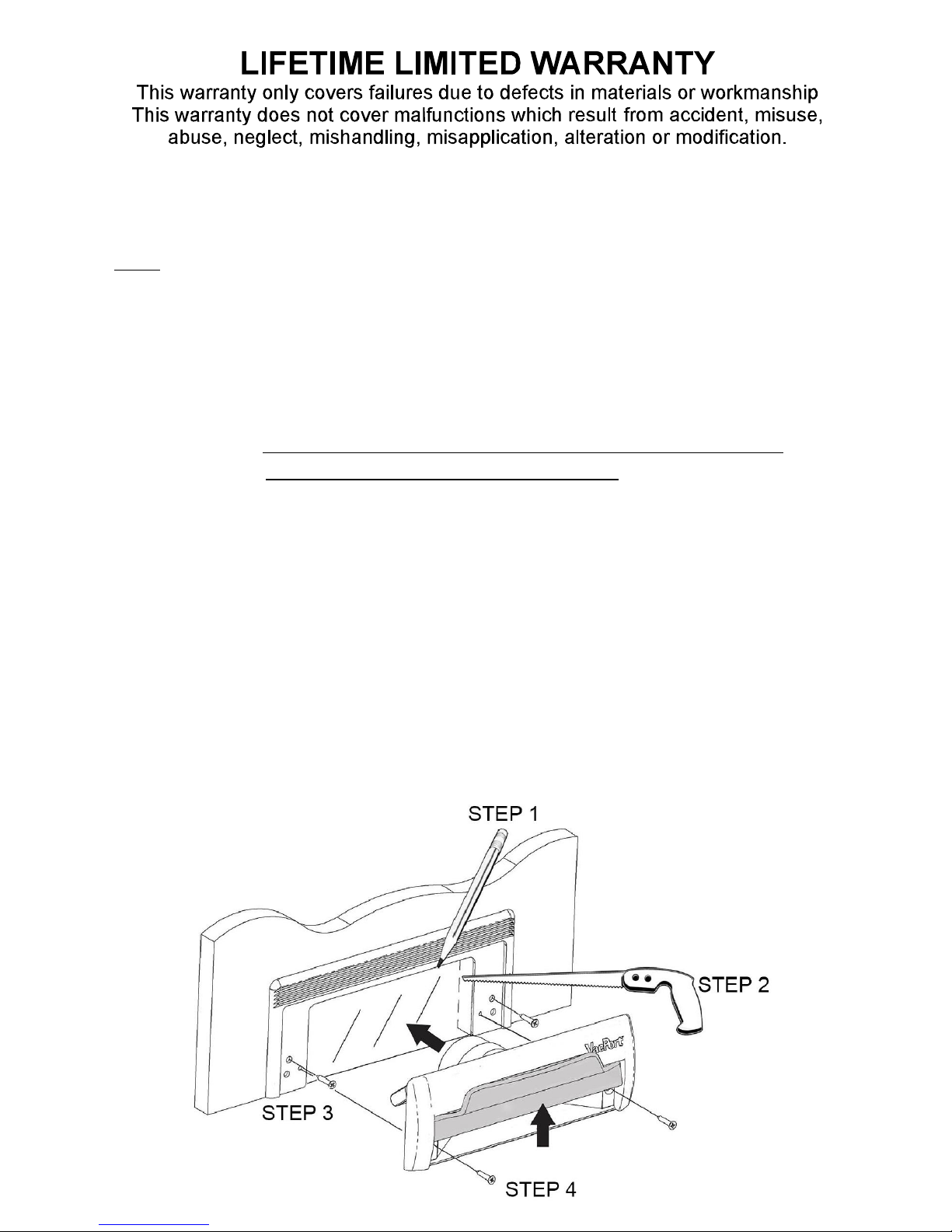
WITH TRIM-PLATE INSTALLED:
1) Your VacPort is supplied with a Trim-Plate in case you need more
height to reach into the cut-out. It is also used as a template to mark
the cut-out. See STEP1. The opening is 6-1/8”wide x 2-1/2”
2) After cutting the hole, STEP2, attach the Trim-Plate with the 2 pan
head screws in one of the outer holes on each side, see STEP3.
3) Connect the VacPort to your central vacuum with 2” diameter flex-hose.
minimum
WITHOUT TRIM-PLATE INSTALLED:
4) If you do not need the Trim-Plate, attach the VacPort directly to the
wall with the 2 flat head screws, see STEP4. Keep Trim-Plate for future
reference.
5) See next page for wire
Connections.
2
 Loading...