

Page 1
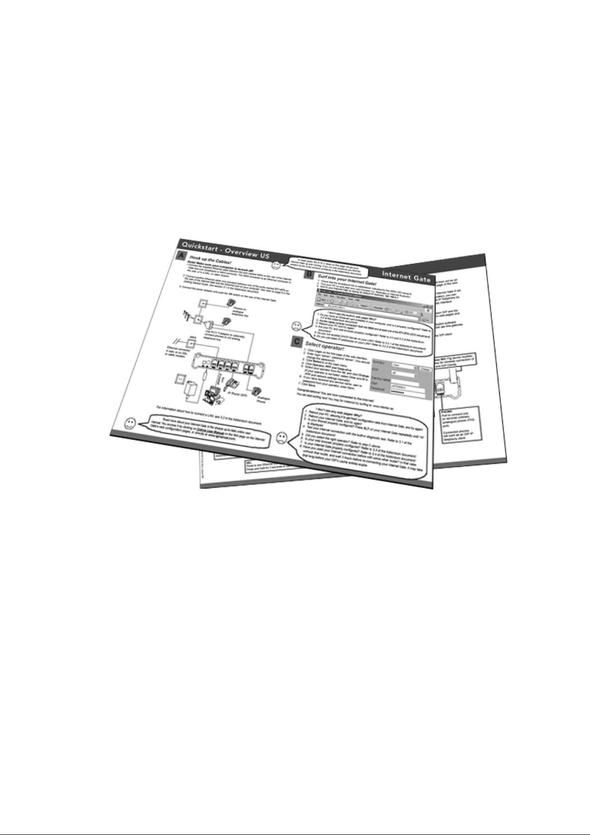
Addendum to the
Quickstart - Overview Sheet
QSadd78-EN-Rev. 07F
To install your ADSL Internet Gate, follow the A, B and C steps of
the Quickstart sheet!
If you run into problems or need further information, this Addendum will help with the most common
issues.
After the installation, you can configure the ADSL Internet Gate for your specific needs through the
built-in web interface. For detailed instructions, use the Online User Guide on the Internet:
www.igmanual.com.
Page 2

Contents
1 Basic Set Up .................................................................................................................................... 3
2 Getting Help..................................................................................................................................... 3
3 Detailed Instructions ........................................................................................................................ 3
3.1 Connecting a Local Network (LAN).......................................................................................... 3
3.2 Check Your PC’s Settings........................................................................................................4
3.2.1 Using the ADSL Internet Gate with Dynamic IP Addresses on the LAN....................... 5
3.2.2 Using the ADSL Internet Gate with Static IP Addresses on the LAN............................ 6
3.3 Check the Proxy Settings of Your Web Browser ..................................................................... 7
3.4 Diagnostic Test......................................................................................................................... 7
3.5 Reset to Factory Defaults......................................................................................................... 8
4 Configuring Your ADSL Internet Gate .............................................................................................8
4.1 Network Settings...................................................................................................................... 9
4.2 Security Profiles ..................................................................................................................... 10
5 Telephone Ports............................................................................................................................. 11
5.1 Using the PHONE Ports with a VoIP Service ........................................................................ 11
5.1.1 Setting up the PHONE ports........................................................................................ 11
5.2 Using the PHONE Ports with the Built-in SIP Server............................................................. 12
5.3 The LINE Port – A Local Gateway to the Telephone Network............................................... 12
5.3.1 Outgoing Calls.............................................................................................................. 12
5.3.2 Incoming Calls.............................................................................................................. 13
5.4 Making and Receiving Calls................................................................................................... 13
5.4.1 Making SIP Calls on a Telephone Connected to a PHONE Port ................................ 13
5.4.2 Making Calls from a SIP Client on the LAN................................................................. 14
5.4.3 Receiving Calls on a Telephone Connected to PHONE Port...................................... 14
5.4.4 Forcing Calls to the Ordinary Telephone Network through the LINE Port................... 14
5.5 Advanced Telephony Functions Using the PHONE Ports..................................................... 14
6 SIP Support.................................................................................................................................... 16
6.1 SIP Communication to and from Your LAN ........................................................................... 16
6.2 SIP Client Configuration......................................................................................................... 16
6.3 Using the Built-in SIP Server.................................................................................................. 16
6.4 Creating Your Own SIP Domain ............................................................................................ 17
6.5 The SIP Switch....................................................................................................................... 17
7 Using the ADSL Internet Gate as an Analog Telephone Adapter on the LAN.............................. 18
8 Requirements................................................................................................................................. 18
- 2 -
Page 3
1 Basic Set Up
Please refer to steps A, B and C of the Quickstart sheet for the basic set up of your ADSL Internet
Gate. It will guide you in installing your ADSL Internet Gate and in doing the necessary settings.
2 Getting Help
HELP!
There are several ways to get information about the ADSL Internet Gate:
• Quickstart Overview Sheet – Helps you install and do some basic configurations.
• Addendum to the Quickstart – Overview Sheet (this document) – Helps you to troubleshoot
the most common issues.
• Built-in Help – Every configuration page on the built-in web interface has help texts that
describe the different parameters. Just click the question marks.
• Online User Manual – In the online manual, you will find the latest information tailored for your
specific version of your ADSL Internet Gate. You access it via links in the Built-in Help, via the
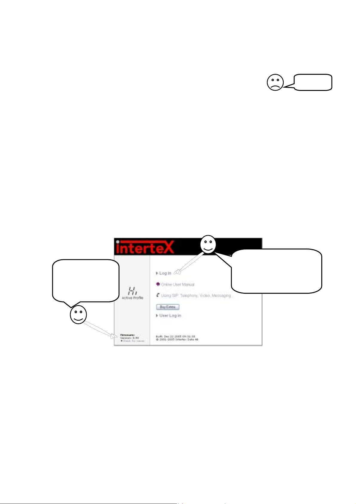
link on the first web page of your ADSL Internet Gate or directly at www.igmanual.com.
• Support – If you experience problems when installing or using your ADSL Internet Gate that
cannot be solved by the help indicated above, contact your retailer for assistance.
• Using SIP: Telephony, Video, Messaging... – This online information accessible from the first
page of the web interface helps you get your IP Telephony and SIP environment up and running.
Surf to your Internet Gate
Upgrade?
Click to check
whether a newer
firmware is available!
by typing its default IP
Address: 192.168.0.1 to
configure it or to get further
help!
3 Detailed Instructions
Do you have problems getting your ADSL Internet Gate to work? Read the installation tips and the
detailed instructions on the following pages for help!
3.1 Connecting a Local Network (LAN)
If you have a Local Area Network (LAN) with several computers you may connect these to the
Ethernet ports of your ADSL Internet Gate. In case there are too few Ethernet ports on your ADSL
Internet Gate, you can connect an Ethernet hub or switch to one of the LAN Ethernet ports and allow
all computers to share the Internet connection.
If your network uses dynamic IP-addressing (recommended), then the built-in DHCP server of your
ADSL Internet Gate will provide IP addresses to all PC:s on the LAN. Refer to 3.2.1 for more
information.
Does your network use static IP addresses? Refer to 3.2.2!
- 3 -
Page 4
Note:
,
• The Ethernet port ET4 is a subnet completely separate from the other subnets. It can be used as
a DMZ for a secure connection of e.g. servers or an Internet connection instead of ADSL.
• The USB port is an option only available one some ADSL Internet Gate models.
3.2 Check Your PC’s Settings
The ADSL Internet Gate is delivered with factory defaults that fit most users. If your PC has the default
network and web settings, then everything should work at once. If not, please check your PC’s settings.
(The steps described here are for Windows XP. Other operating systems have similar menus and
options, though accessing them may be done differently.)
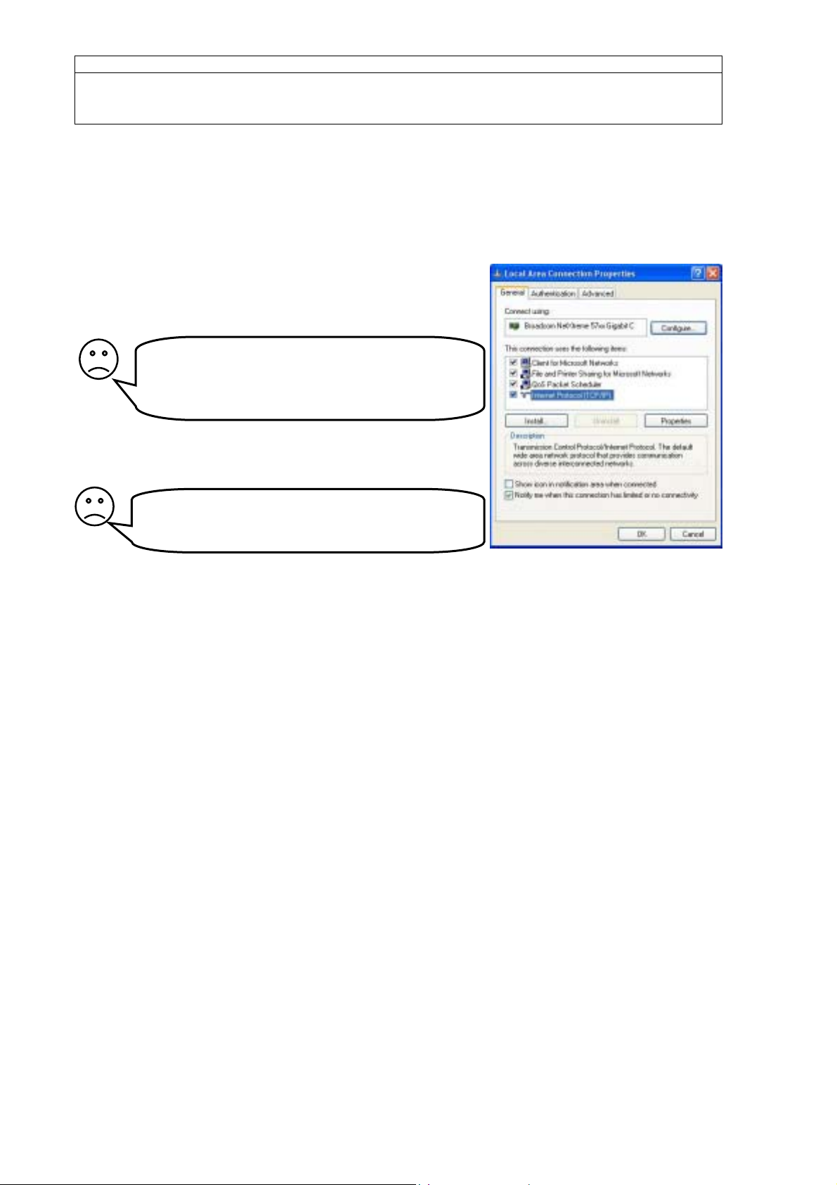
• Select Network Connections in Windows Control Panel
(click Start and choose Control Panel). Right click on the
network connection that you use and select
Properties.
I can’t find “Network Connections”! Why? You
need a network card installed in your computer.
Configure it according to the instructions from the
manufacturer.
• Double click on Internet Protocol (TCP/IP) for your
network card on the list that appears.
There is no ”Internet Protocol (TCP/IP)” in the
list! Why? It is not installed.
Select ”Install”
There are two ways to address computers in a local network (LAN):
a) Either Dynamic IP addressing, a DHCP server on the LAN distributes IP addresses to all
connected computers,
b) or Static IP addressing, all connected computers use a manually assigned IP address.
”Protocol”, “Add”, ”Microsoft
- 4 -
Page 5
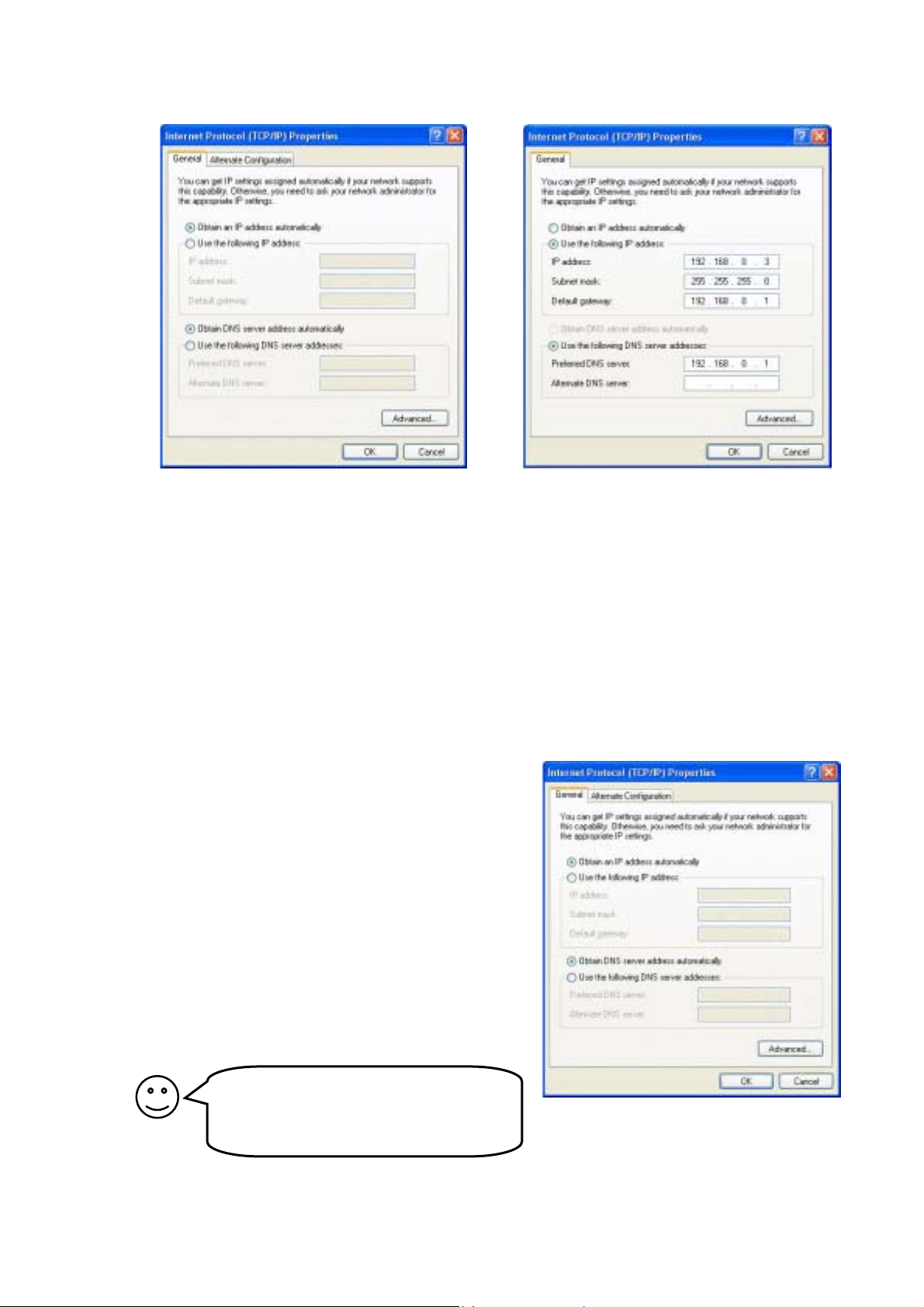
Check how your computer is configured to receive an IP address:
g
a) If it is configured to use dynamic addressing,
the settings look like this:
No configuration is needed. The DHCP
server built into your ADSL Internet Gate
will distribute correct IP addresses.
Check your settings according to 3.2.1, 3.3,
and 3.4.
b) If it uses static IP addresses the setting look
something like this:
You have two options:
1 (recommended): Configure all computers
on your LAN to use dynamic IP addressing.
Refer to 3.2.1 for more information.
2: Configure your ADSL Internet Gate and
your PC:s so they fit your LAN. Refer to
3.2.2 for more information.
3.2.1 Using the ADSL Internet Gate with Dynamic IP Addresses on the LAN
The ADSL Internet Gate is delivered conf igured for dynami c IP addre ssing on t he LAN. It acts as a DHCP
server and provides IP addresses.
(The steps described here are for Windows XP. Other operating systems have similar menus and
options, though accessing them may be done differently.)
All PCs on your LAN should be co nfigured li ke this:
1. Select Network Connections in Windows Control
Panel. Right click on the network connection that
you use and select Properties.
2. Double click on Internet Protocol (TCP/IP) for
your network card on the list that appears.
3. Select Obtai n an IP address automatically and
Obtain DNS server address automatically.
4. Click OK to save and close all windows and reboot
the PC.
5. You may check that the built-in DHCP server of
your ADSL Internet Gate is enabled, by checking
the settings of the LAN ports in the Network
Settings web page.
If you already run a DHCP server on your
LAN you should turn it off or change its
settings to distribute the ADSL Internet
Gate as default
ateway.
- 5 -
Page 6
3.2.2 Using the ADSL Internet Gate with Static IP Addresses on the LAN
Note:
This information is intended for advanced users. If you are not familiar with terms like static IP
addressing you do not need to read this chapter. Refer to 3.2.1 instead.
If you want your ADSL Internet Gate to be part of an existing LAN that uses static IP addresses, you
have to change its LAN IP address to an unused IP address that fits the same subnet as your LAN.
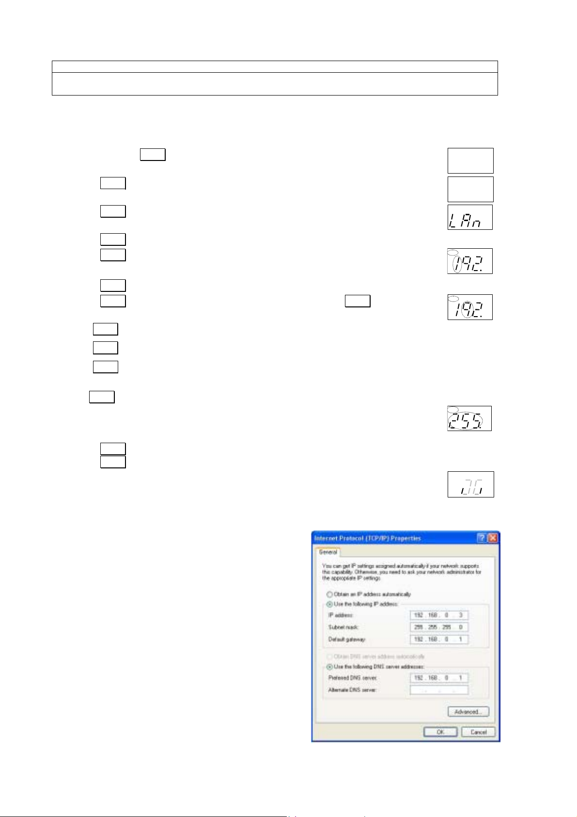
You can use the keys on the front panel to change the IP address:
AD CFG DHP RST
1. Press and hold SET pressed for 3 seconds, to enter setup mode.
2. Press SEL once, so “CFG” is lit.
3. Press SEL repeatedly until ”LAn” appears in the display
4. Press SET .
5. Press SET . The first 3 digits of the IP address are shown and the first digit flashes.
6. Press ALT repeatedly, until the correct digit is displayed.
7. Press SEL . The next digit flashes, and can be changed using ALT .
8. Use SEL to step through all digits of the IP address.
AD CFG DHP RST
AD CFG DHP RST
AD CFG DHP RST
AD
CFG DHP RST
LQ
TX
RX
LQ
TX
RX
LQ
TX
RX
LQ
TX
RX
LQ
TX
RX
Use SET to step back to the previous digit if you need to make corrections.
Use ALT to change the value of the flashing digit.
You can cancel the IP address set-up, without saving any changes, by pressing
the SEL key and holding it pressed for 2 seconds.
AD CFG DHP RST
9. After stepping through all digits of the IP address, the subnet mask appears and can
be modified. Each subnet mask number can only be set to values 255, 254, 252, 248,
240, 224, 192, 128, or 0.
10. Press ALT repeatedly, until the correct value is displayed.
Press SEL to step to the next subnet mask number.
AD CFG DHP RST
11. When all digits have been displayed the IP address and subnet mask are saved.
12. Complete the installation with the steps on the next page.
(The steps described here are for Windows XP. Other operating systems have similar menus and
options, though accessing them may be done differently.)
The procedure below has to be performed for all
computers connected to your local network (LAN).
1. Select Network Connections in Windows Control
Panel. Right click on the network connection that
you use and select Properties.
2. Double click on Internet Protocol (TCP/IP) for
your network card on the list that appears.
LQ
TX
RX
LQ
TX
RX
3. Select Use the following IP address.
4. Enter the IP address and Subnet mask of the
computer.
5. As Default gateway and Preferred DNS server
enter the IP address of your ADSL Internet Gate.
Either the default 192.168.0.1 or the one you
entered in the previous section.
6. Click OK.
- 6 -
Page 7
3.3 Check the Proxy Settings of Your Web Browser
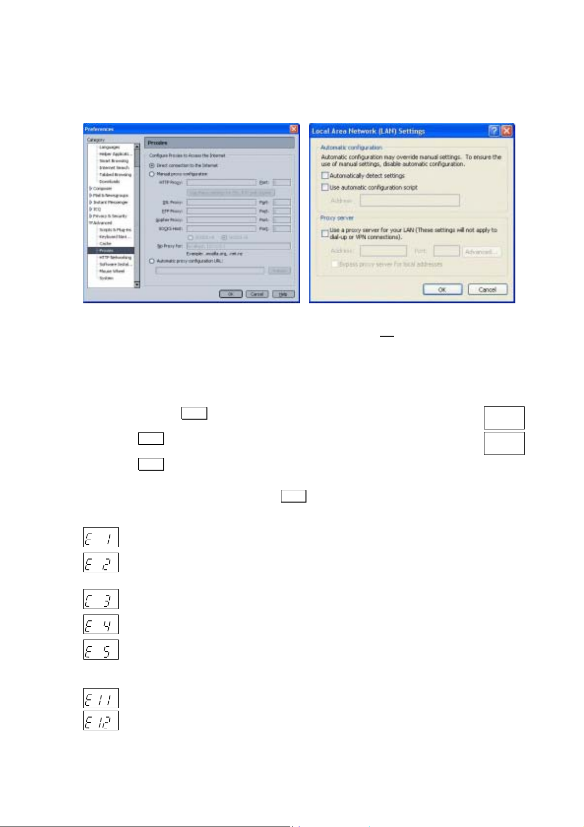
If your web browser is configured to use a proxy server, you may have problems reaching the built-in
pages of your ADSL Internet Gate. In that case, disable the proxy server in your browser:
Netscape Navigator:
Select Edit, Preferences, Advanced, Proxies.
”Direct connection to the Internet” should be selected.
Internet Explorer:
Select Tools, Internet Options, Connections, LAN
settings. The checkbox ”Use a proxy-server for
your LAN” must not
be selected.
3.4 Diagnostic Test
If you cannot access the Internet, your ADSL Internet Gate can attempt to localise the problem.
Start the diagnostic test like this:
AD CFG DHP RST
1. Press and keep SET pressed 3 seconds to enter setup-mode.
2. Press SEL repeatedly until “LQ” is lit.
3. Press SET .
AD CFG DHP RST
LQ
TX
RX
LQ
TX
RX
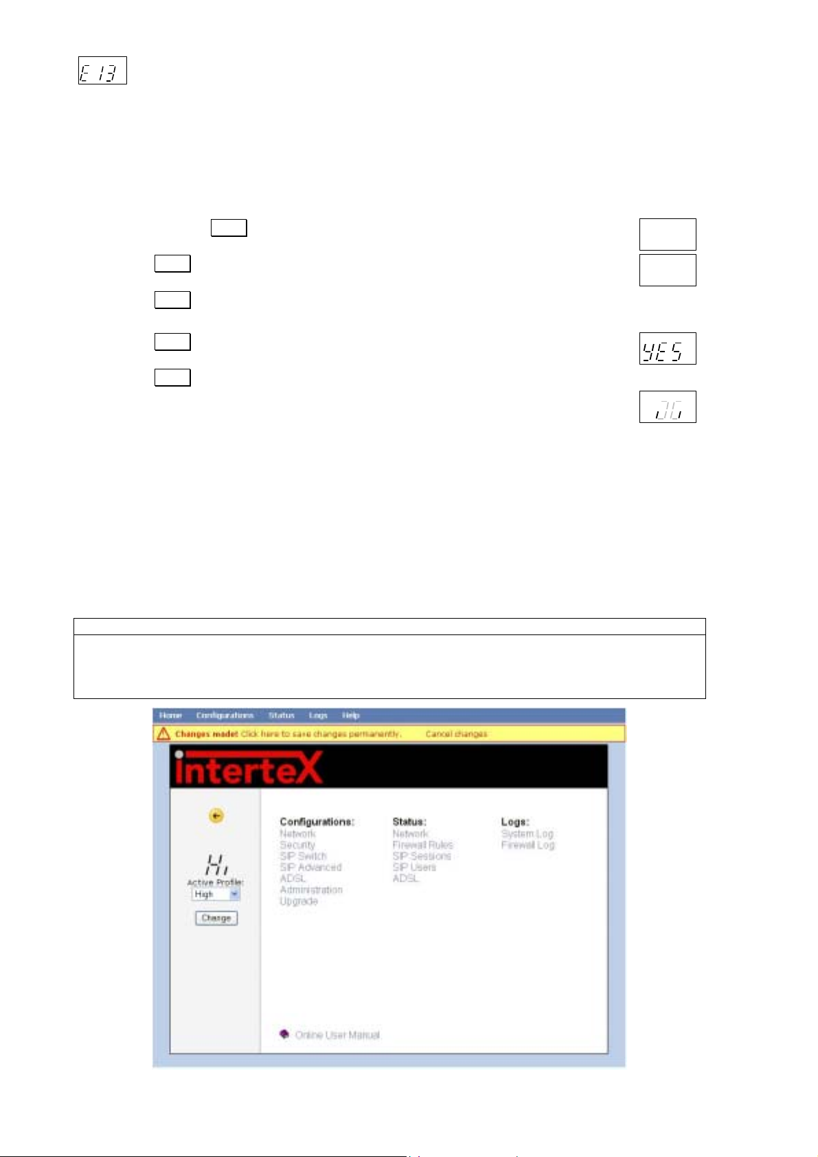
It takes a couple of seconds to perform the test. Any errors discovered are shown in the display. The
diagnostic test can find multiple errors, press SEL to flip through all error messages.
”E 1” to ”E 9” indicate errors in your external Internet connection (WAN):
AD CFG DHP RST
AD CFG DHP RST
No WAN link connection. Check all cables. Contact your broadband-supplier if the error
LQ
TX
RX
remains.
No WAN DHCP server found. This may be O K , bu t c h e ck configura tion according to 3.4.
LQ
TX
RX
Reboot your ADSL Internet Gate. Contact your Internet Service Provider (ISP) if the error
remains.
AD CFG DHP RST
AD CFG DHP RST
AD CFG DHP RST
No Gateway found. This may be OK , bu t ch e ck configuration according to 3.4. Reboot your
LQ
TX
RX
ADSL Internet Gate. Contact your Internet Service Provider (ISP) if the error remains.
No DNS server found. Check configuration according to 3.4. Reboot your ADSL Internet
LQ
TX
RX
Gate. Contact your Internet Service Provider (ISP) if the error remains.
No Internet connection. You do have a connection to your ISP, but they have no Internet
LQ
TX
RX
connection at the moment. Contact your Internet Service Provider (ISP) if the error remains.
”E11” to ”E19” indicate errors in your local network (LAN):
AD CFG DHP RST
AD CFG DHP RST
No Ethernet link. Check the cables connected to the ET ports.
LQ
TX
RX
No DHCP addresses requested. The DHCP server of the ADSL Internet Gate is on, but no
LQ
TX
RX
PC:s on the LAN have requested addresses. This may be OK, but check your settings, see
3.2.1.
- 7 -
Page 8
AD CFG DHP RST
No Ethernet packets at all received. This may be OK, but check your settings, see 3.2 and
LQ
TX
RX
3.4.
If no error messages are shown, then your Internet connection is OK. Any remaining error is probably
due to your PC’s settings. See 3.2 for more information!
3.5 Reset to Factory Defaults
If you wish to you can reset all settings to their original values, so your ADSL Internet Gate is set up
the same way as when delivered from the factory.
AD CFG DHP RST
1. Press and hold SET pressed for 3 seconds, to enter setup mode.
2. Press SEL repeatedly until ”RST” appears in the display.
3. Press SET .
4. The question ”Clear all?” appears, and then ”no”.
5. Press SEL to choose ”YES”.
6. Press SET .
7. The ADSL Internet Gate now resets and then restarts.
AD CFG DHP RST
AD CFG DHP RST
AD CFG DHP RST
LQ
TX
RX
LQ
TX
RX
LQ
TX
RX
LQ
TX
RX
4 Configuring Your ADSL Internet Gate
Your ADSL Internet Gate is delivered with factory settings that fit most users. In some situations
however, you need to change the configuration of your ADSL Internet Gate. All the configuration
pages can be reached from the main menu in the ADSL Internet Gate. You can also easily set up the
ADSL Internet Gate to fit your specific needs.
In the following sections you will find information about two of the configurable features in the ADSL
Internet Gate. For more information refer to the built in help or the online user manual, see also
section 2.
Note:
When you have made changes in the GUI, click Apply to activate the settings. To save the settings
permanently click on Save permanently at the top of the page. Changes that are not permanently
saved will disappear if the unit is restarted. When there are changes that have not been saved
permanently a warning is displayed at the top of the page as well as the text CFG in the display.
- 8 -
Page 9
To access the built-in network configuration pages of the ADSL Internet Gate, do the following:
yp
1. Start a web browser, such as Internet Explorer or Netscape Navigator, on your PC.
2. Write the IP address of your ADSL Internet Gate, 192.168.0.1, in the address field of the
browser. The first web configuration page should appear.
3. Click Log in.
4. Enter User name and Password. (At delivery: User name=admin, Password=admin. You
should change the password!)
4.1 Network Settings
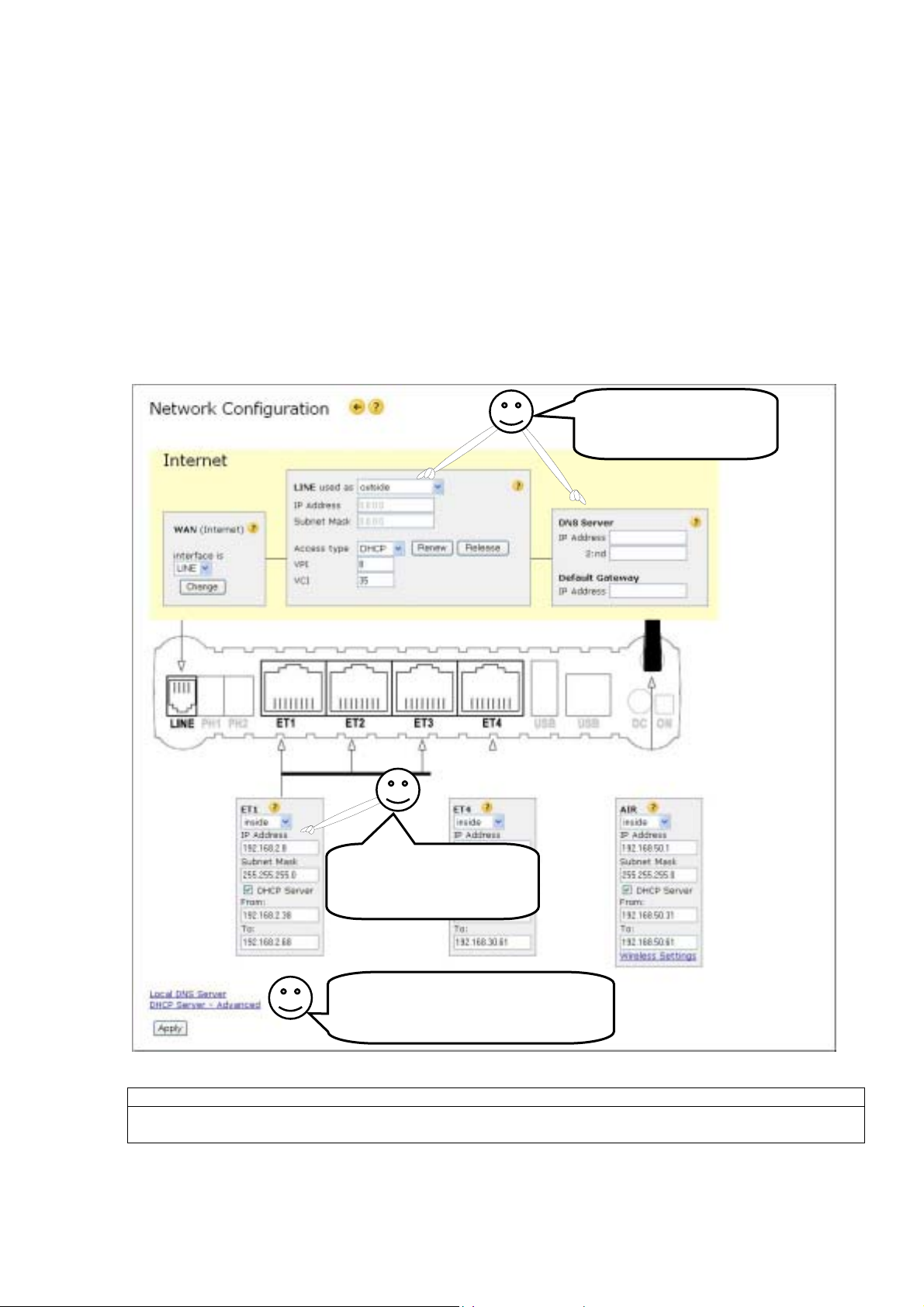
You can edit the network settings by choosing Network under Configurations on the menu page.
Select access type DHCP, PPPoE or PPPoA depending on the type of connection you have received
from your Internet provider. If you are not sure what to select choose Auto and click Search. If you
have received a user name and password from your Internet provider enter those before you click
Search. To configure the line parameters manually select access type Manual.
These fields are filled
automatically if “Access
t
e Auto” is selected.
How do I configure the
LAN connections? Refer
to 3.2, 3.2.1, and 3.2.2!
Do not forget to click Apply and
then the link at the top of the page
to save the settings permanently!
Note:
Each of the interfaces ET1-3, ET4, USB and AIR must reside on separate subnets. Two interfaces cannot
have the same IP address – even if one of them is blocked!
- 9 -
Page 10
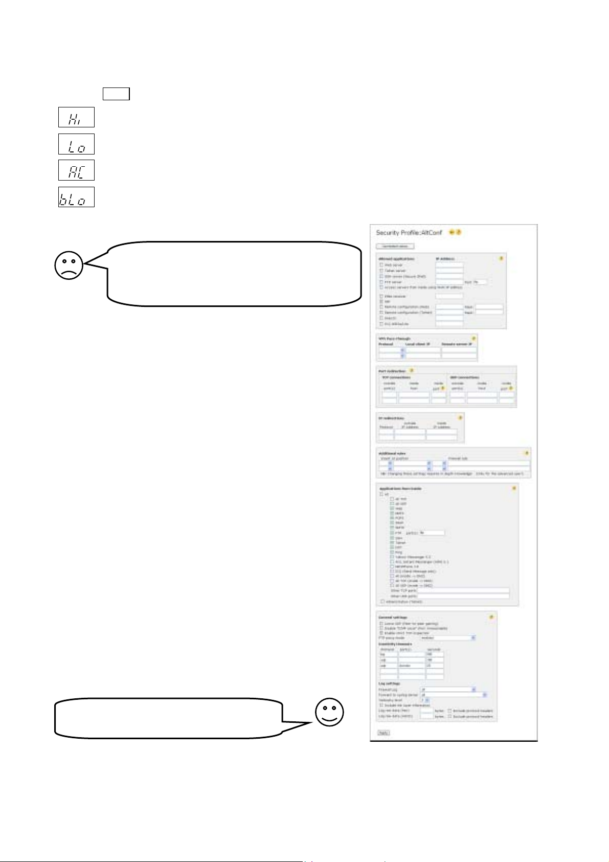
4.2 Security Profiles
The firewall supervises the data traffic passing through the ADSL Internet Gate and stops
unauthorised traffic. The active security level is shown on the front panel display. It can be changed
using the ALT key, or the menu page on the built in web interface.
AD CFG DHP RST
AD CFG DHP RST
AD CFG DHP RST
AD CFG DHP RST
If you have:
Only web and email traffic is allowed - Highest security, but some applications may have
LQ
TX
RX
trouble passing through.
All outgoing and legitimate incoming traffic is allowed - Same security against attacks as
LQ
TX
RX
the Hi profile, but more applications are allowed to access the Internet.
User editable security profile - The user may edit the details for this security profile.
LQ
TX
RX
Blocked - No traffic is allowed to pass. You are disconnected from the Internet.
LQ
TX
RX
Does your application have trouble getting out
on the Internet?
Do you get error messages?
Change security profile to “Lo”!
• Servers that you want to make accessible from the Internet,
• a VPN client to work from home, or
• use network games (games played together with other users
on the Internet),
you have to configure the firewall to allow such traffic to pass.
You can edit the firewall settings by choosing Security under
Configurations on the menu page. Then choose AC to edit the
security profile to fit your games or applications.
Select the applications and/or protocols you want to allow through
the firewall. For some applications you need to state the IP
address of the computer on your LAN that will receive the traffic. It
is the IP address to your local computer you should enter. In
Windows choose Start, Run, and enter cmd. Write ipconfig to
find out what IP address your computer is assigned to.
Under Allowed applications and Port redirection you state the
applications, ports and protocols you want to allow to pass in
through the firewall.
Under Applications from inside you state applications, ports and
protocols that you want to allow to pass out through the firewall.
Once an application or protocol has been let through the firewall, a
two-way connection is established through the firewall and data
can pass in both directions.
Advanced users may manually redirect ports and even edit the
rules controlling the firewall in a powerful command language.
Do not forget to click Save and change the
profile to AC if you make any changes!
- 10 -
Page 11
5 Telephone Ports
j
Certain models of this product are equipped with one or two PHONE ports and a LINE port.
Ordinary analog telephones plugged into the PHONE ports (also referred to as FXS ports), become
SIP clients that can be used for VoIP (Internet telephony). The PHONE ports are pre-configured to use
the internal SIP server, but can easily be changed to use a SIP based IP telephony service from a
service provider. The green PH lamp on the front panel will be lit green once your phone has become
registered to a SIP server.
The LINE port (also referred to as FXO port), can be connected to your ordinary analog telephone line
and then becomes a local gateway between the old telephone system (the PSTN) and SIP based
Internet telephony (VoIP).
For additional help please click on the question mark
appearing help text is not sufficient, the “Read more online” links might explain further.
visible on each configuration web page. If the
5.1 Using the PHONE Ports with a VoIP Service
If this product has been bundled for use with a special VoIP service, that service provider should have
included detailed instructions on how to set up the telephone ports for his service, or the service
provider may even use an automatic provisioning system. In these cases, please follow the
instructions provided by the service provider!
If you want to connect a PHONE port to a VoIP service that does not have specific instructions for
configuring this product, please read the next paragraph!
5.1.1 Setting up the PHONE ports
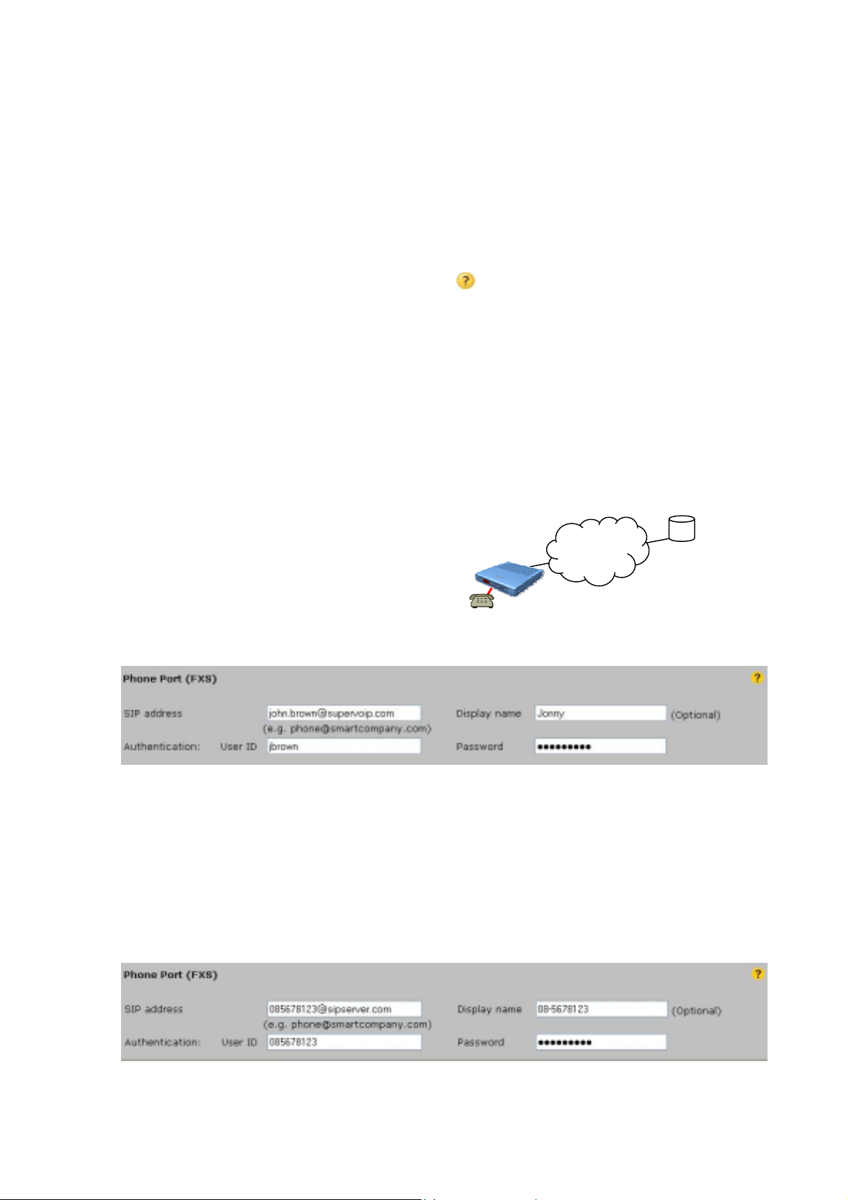
You should have received a SIP account from
the VoIP service provider. To make a PHONE
port of this product register to the SIP server of
the provider, you shall enter the SIP address,
the User ID and the Password on the
Telephony Ports page of the ADSL Internet Gate.
After pressing Save, the PHONE port should be
registered to the SIP server and the PH led
should turn green.
Internet
Service Provider’s
supervoip.com
A SIP address is similar to an email address, but many service providers do not expose the SIP
address used, but instead give a “phone number” and “SIP proxy” or “SIP server”. The SIP address is
then usually the combination of those two with an @ character between.
E.g. if your ”phone number” is 085678123 and the “SIP proxy”, “SIP server” or “SIP registrar” is
sipserver.com, then the SIP address to enter is [email protected].
User ID is sometimes called “authentication ID” or just “user name” and is often the same as the
phone number or the part before the @-sign in the SIP address.
Password is sometimes called “authentication key” or similar.
The configuration may then look like (use any display name you desire):
The ADSL Internet Gate automatically handles the “outbound proxy” function. Only if a service
provider really requires his “outbound proxy” to be used, it should be entered on the SIP Switch page.
- 11 -
Page 12
5.2 Using the PHONE Ports with the Built-in SIP Server
Your unit includes a standalone SIP server. With the factory
settings, the PHONE port is given the name 1111, making it
automatically register to the internal SIP server, using the SIP
Internet
address 1111@<ip adress>, e.g. [email protected]. If the unit
has a second PHONE port, its factory name is 2222. Phones
connected to these ports can reach each other by just dialing
Built-in SIP server
these 4-digit numbers followed by the # key.
Please read chapter 6.3 on how to give your SIP server a
symbolic domain name and make it globally accessible.
On the Telephone Port page, you can of course change the SIP address of the PHONE port. If only a
SIP user name is given (i.e. the @
server. By default, all the PHONE ports and SIP clients on the LAN are allowed to register on the
<domain> part left out), the phone will be registered on the internal SIP
internal SIP server. SIP clients on the outside of the ADSL Internet Gate firewall, need to use their
User IDs and Passwords for authentication. This is configured on the SIP Switch page.
5.3 The LINE Port – A Local Gateway to the Telephone Network
The LINE port (connected to your old telephone line) allows SIP clients to reach the ordinary
telephone network (PSTN) and vice versa. The functions of the LINE port can be used in addition to
the PSTN connectivity offered by a VoIP service provider, e.g. for back up, for emergency calls or for
receiving incoming calls on your old telephone line. You configure the LINE port on the Telephone
Port page, reachable from the main menu.
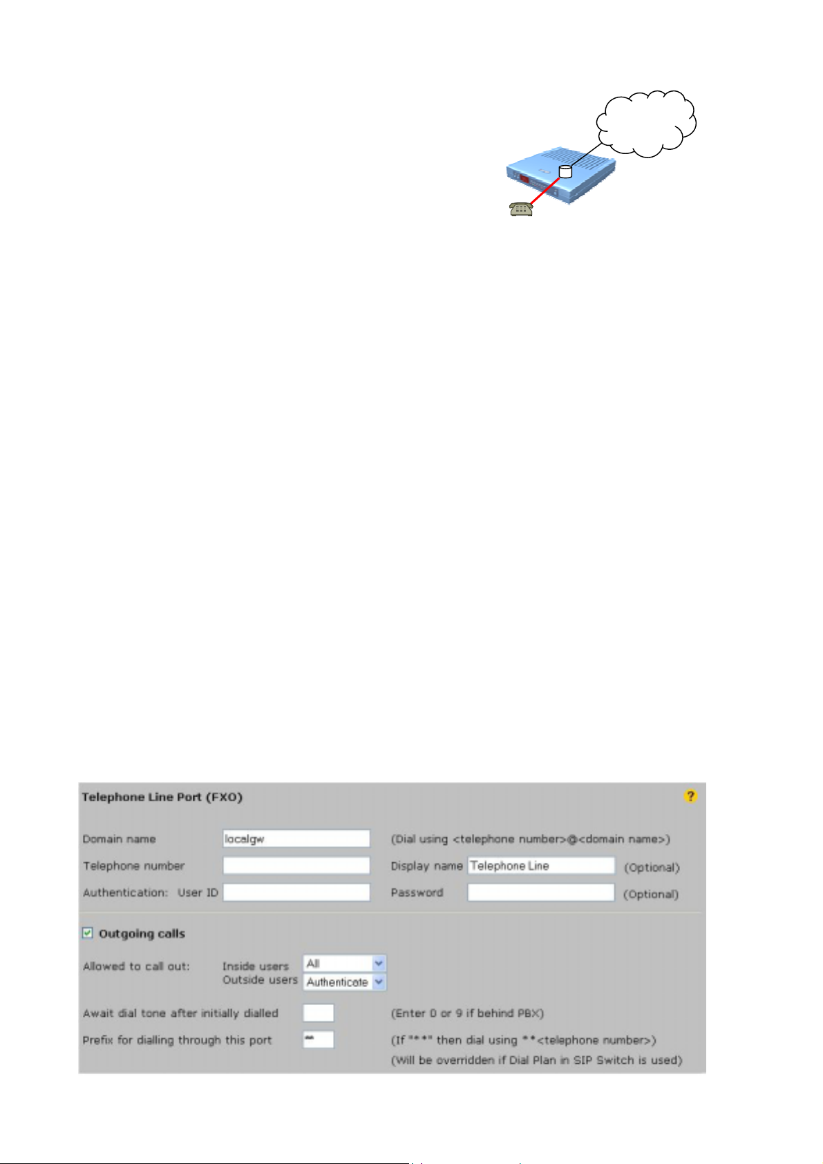
5.3.1 Outgoing Calls
Normally, a telephone number dialed on a SIP client is sent to the VoIP service provider for handling.
However, SIP calls can also be forced to the ordinary telephone network through the LINE port by:
• Prefix
The dial prefix is ∗∗ by default, but can be changed on the Telephone Port page. Dialing
∗∗<telephone number> on any telephone connected to the PHONE ports or on any SIP client on
the LAN, will call that telephone number through the LINE port.
• Virtual domain name
The virtual domain name is by default “localgw” but can be changed on the Telephone Port page.
Any SIP client calling <telephone number>@localgw will dial the stated telephone number through
the LINE port
*
Some SIP phones may require entering the local IP address of your unit (by default 192.168.0.1) as
“outbound proxy” in their configuration for this feature to work. Alternatively you can enable the built-in DNS
server. The DNS Server web page is accessible from the main menu through the Network Configuration web
page. If you own a valid second domain name (other than for your SIP server) you can use that domain name
instead of localgw.
*
.
- 12 -
Page 13
• Emergency number
Emergency numbers are forced to the LINE port as set up on the SIP Switch page.
• The SIP Switch Dial Plan
If you purchase the optional SIP Switch software, the Dial Plan on the SIP Switch page can be
used to route telephone calls through the LINE port, in many useful ways.
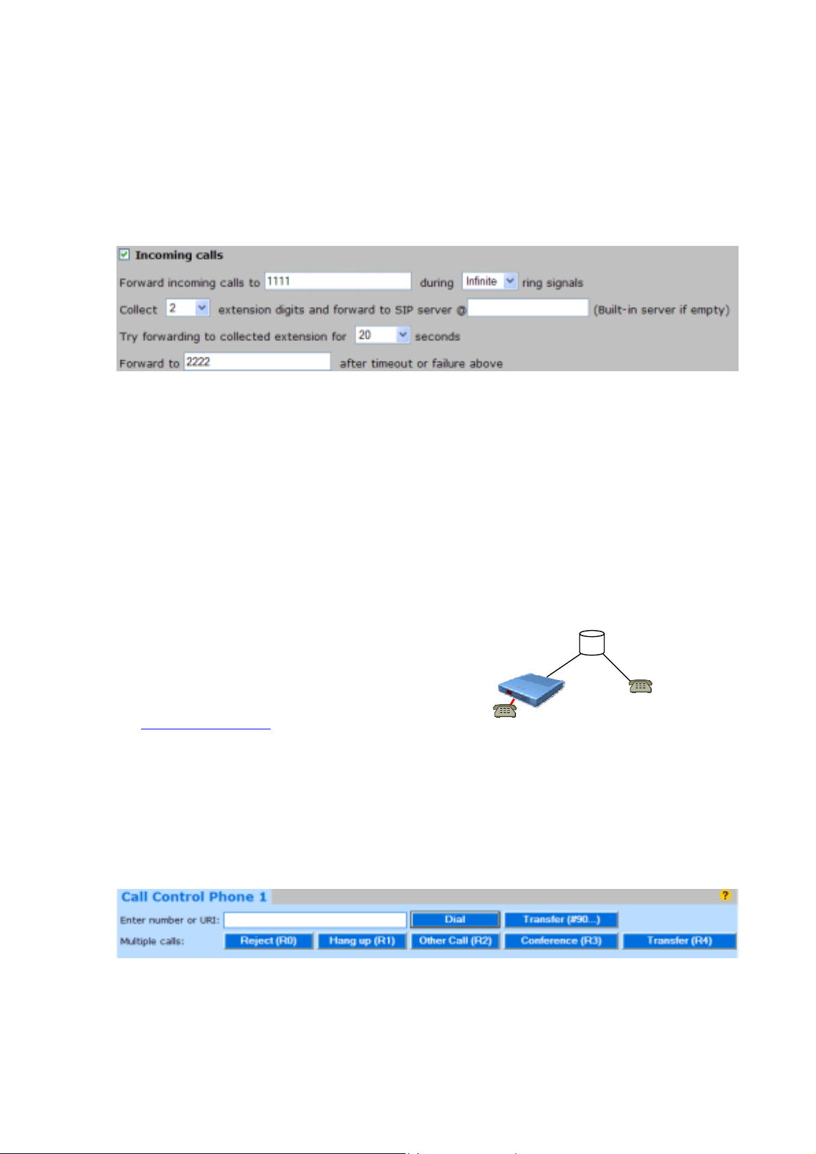
5.3.2 Incoming Calls
If anyone calls the telephone number of the phone line connected to the LINE port, the call will by
default be forwarded to the telephone connected to the PHONE1 port.
This behavior can be changed on the Telephone Port page. If you for example have a SIP Client on
you laptop PC, with SIP address [email protected], you just enter that SIP address in the
Forward incoming calls to field, to allow you to pick up calls on your laptop e.g. while traveling and
connected to an Internet connection not blocked for SIP.
You can also set up more advanced functions, like collection of extension digits and directly allow
forwarding of incoming calls to certain SIP clients. This works if you have given your SIP clients
numeric SIP user names, or if you use the extension number feature of the optional SIP Switch
software, see chapter 6.5.
5.4 Making and Receiving Calls
5.4.1 Making SIP Calls on a Telephone Connected to a PHONE Port
An analog telephone connected to a PHONE port becomes a SIP client.
You can call numeric SIP addresses on the same SIP
domain as you are registered to by simply picking up
the phone and dialing.
Example:
If you are registered on sipserver.com and want to
call [email protected]
the phone and dial 5678#.
When a conventional telephone number is dialed, the VoIP service provider normally detects this and
sends the call trough a gateway to the old telephone network, the PSTN.
To speed up dialing it is recommended that you end all your dials by pressing #, to avoid a 4
second delay before the call is placed.
To dial alphanumeric SIP addresses, or full SIP addresses on other SIP domains, you can use the
Call Control panel on the Telephone Port page. Just enter the SIP address and click Dial. You can
also enter ordinary telephone numbers or extension numbers.
all you need to do is pick up
sipserver.com
If your phone is On Hook when dialing from the Call Control panel, it will ring to remind you to pickup when a connection is made.
The same Call Control panel can also be reached by clicking on User Log In on the login page of
your unit and entering the SIP name and password you have entered for that PHONE port on the
Telephone Port page.
- 13 -
Page 14
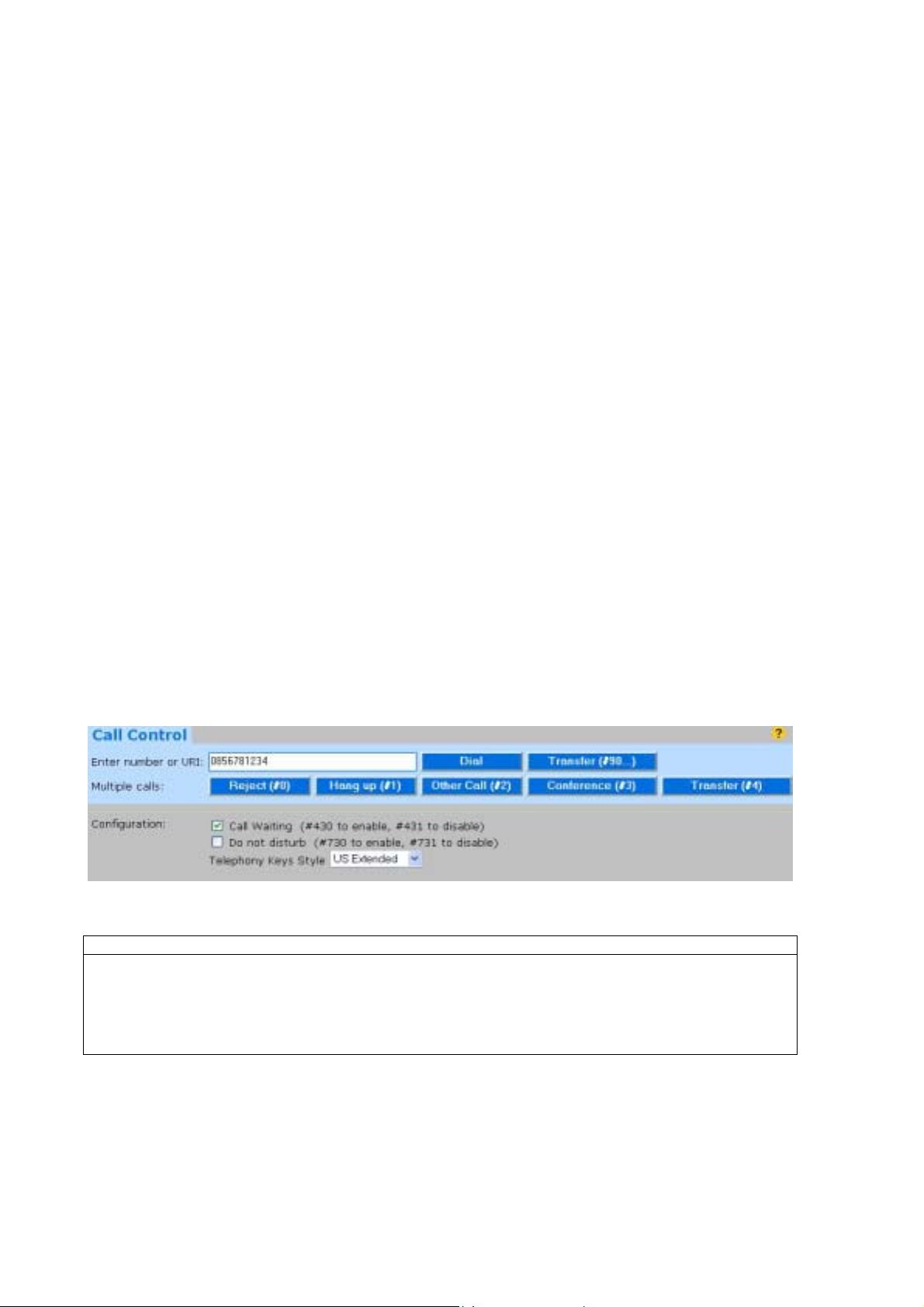
For advanced telephony functions, please refer to chapter 5.5.
5.4.2 Making Calls from a SIP Client on the LAN
No special settings in the ADSL Internet Gate are required for SIP clients on the LAN, since the unit
contains a SIP proxy that dynamically controls the firewall and NAT inside the ADSL Internet Gate. In
the clients, make sure STUN and other NAT-traversal methods are turned off. Configure the
clients as if they had a global IP address, disregarding that they are behind the NAT/Firewall in the
ADSL Internet Gate. If an “outbound proxy” setting has to be set in the client’s configuration, it is best
to set it to the local IP address of this unit (by default 192.168.0.1).
By clicking “Using SIP: Telephony, Video, Messaging…” on the login page of the ADSL Internet Gate,
you will find guidelines how to configure various SIP Clients and SIP Phones.
5.4.3 Receiving Calls on a Telephone Connected to PHONE Port
The telephone connected to the PHONE port becomes a SIP client. Thus, calling its SIP address from
any SIP phone anywhere in the world will make it ring (unless your VoIP service provider has blocked
reception of real SIP calls). If you have received an ordinary telephone number from your VoIP service
provider, he is responsible for forwarding PSTN calls with that number to your SIP address. Your
phone’s SIP address is visible on the Telephone Port page.
5.4.4 Forcing Calls to the Ordinary Telephone Network through the LINE
Port
Dialing ∗∗ in front of the telephone number will place the call on the ordinary telephone network using the
LINE port. Thus, for example dialing ∗∗5551234# will call the ordinary telephone at number 555 1234.
This applies to both to phones connected to the PHONE ports and to SIP clients connected to your LAN.
See chapter 5.3.1 how the ∗∗ prefix can be changed and learn about other ways of using the LINE port.
5.5 Advanced Telephony Functions Using the PHONE Ports
The telephones connected to the PHONE ports are capable of advanced call control operations like
call transfer, 3-way calling, call waiting etc.
You use those functions either by pressing certain keys on the telephone or by using the Call Con trol
panel on the Telephone Port page (which is easier).
The key combinations to activate different functions are dependant on the Telephony Keys Style
setting of the Telephone Port page. The description below is for the “US Extended” keys style.
Note:
Your unit may use different dial sequences than described here! To see the dial sequences for
your unit please refer to your unit’s Telephone Port page: The sequences to dial from the phone
are shown within parenthesis on each button in the Call Control Panel.
The hook flash key is marked R in some countries.
2nd Call
Park active call and start a second call:
Enter the number and click the Dial button
- 14 -
Do a hook-flash and dial the number
OR
Page 15

Hang up waiting or parked call
Click the Reject button
Dial #0 (as stated on the Reject button)
OR
Hang up active call
Click the Hang up button
Dial #1 (as stated on the Hang up button)
OR
Call Alternation
If you have an active and a parked call, or a call waiting, you can swap between them:
Click the Other Call button
Dial #2 (as stated on the Other Call button)
OR
3-way Conference
If you have an active and a parked call you can join them into one 3-way conference call:
Click the Conference button
Dial #3 (as stated on the Conference button)
OR
Attended Call Transfer (Note that the other party needs to support Call Transfer.)
If you want to transfer a call to another number after you have spoken to that person:
Enter the number and click the Dial button,
wait for an answer, then press the Transfer
button next to the Conference button.
Do a hook-flash and dial the number, wait for
an answer, then dial #4 (as stated on the
OR
Transfer button).
Unattended Call Transfer (Note that the other party needs to support Call Transfer.)
If you want to blind transfer a call to another number:
Enter the number and click the Transfer
button next to the Dial button.
Do a hook-flash and dial #90 (as stated on the
OR
Transfer button) followed by the number.
“Hook flash for everything”
With certain Telephony Key Styles you can also use the hook flash in the following situations:
Call waiting
If you hear the “call waiting”
beep during a call you can hook
flash to switch between the two
calls.
Call transfer
When you have received a call,
do a hook flash to get dial tone,
and dial the third party. Wait for
answer then hook flash to
transfer the call.
3-way Conference
Place the first call, wait for an
answer. Hook flash and dial the
third party, wait for an answer.
Hook flash to join both calls into
a 3-way conference call.
(The hook flash key is marked R in some countries)
You can freely mix using Control Panel buttons, dial codes and hook flash in any combination.
- 15 -
Page 16
6 SIP Support
SIP is a standardized Internet protocol for live person-to-person communication over the Internet.
VoIP or IP Telephony is just one application where SIP is used. Other applications, such as SIP based
high quality voice, video, presence, instant messaging and more is expected to be the next large
usage of the Internet after email and web surfing!
However, SIP (and other similar protocols) does not traverse firewalls and NAT routers, unless the SIP
protocol is specifically supported.
Your ADSL Internet Gate unit has full support for SIP!
6.1 SIP Communication to and from Your LAN
To allow SIP communication to and from clients on the LAN, the ADSL Internet Gate contains a full
SIP proxy and SIP registrar that dynamically control the NAT and firewall in the ADSL Internet Gate.
Thus, SIP clients on the LAN can communicate with other SIP clients over the Internet.
With other NAT routers and firewalls, SIP communication may not be possible, or has to rely on
unreliable and insecure methods like STUN to try to keep doors open in your firewall. Some of these
methods for NAT/Firewall traversal also locks to only use SIP with a certain service provider. They do
not allow you to use the SIP protocol generally.
The SIP support in the ADSL Internet Gate allows for global and secure SIP communication and
requires no configuration – it just works! SIP Clients on the LAN just follow the SIP standard. Make
sure that STUN and other NAT traversal methods are turned off in the SIP clients you use!
For additional help please click on the question mark
appearing help text is not sufficient then the “Read more” online links below it might explain further.
visible on each configuration web page. If the
6.2 SIP Client Configuration
No special configuration of the ADSL Internet Gate is required for SIP clients on the LAN. In the SIP
Client, make sure STUN and other NAT-traversal functions are turned off.
Just configure the clients as if they were located on a global IP address and disregard that they are
behind the NAT/firewall in the ADSL Internet Gate. If there is any “outbound proxy” setting available in
the client’s configuration you may set it to the local IP address of this unit (by default 192.168.0.1),
though it is not necessary. SIP clients can register to any SIP servers on the Internet. (Registering to
more than 5 accounts requires purchase of additional licenses.)
You find guidelines how to configure various SIP clients and SIP phones by clicking “Using SIP:
Telephony, Video, Messaging” on the login page of the web interface.
6.3 Using the Built-in SIP Server
Your ADSL Internet Gate can also act as a complete standalone SIP server. You can register both
local (LAN) and remote (WAN) SIP clients to your own unit, enabling global SIP communication
without using an external SIP server. Note that you can use the internal SIP Server at the same time
as being SIP transparent and using a VoIP provider’s SIP services!
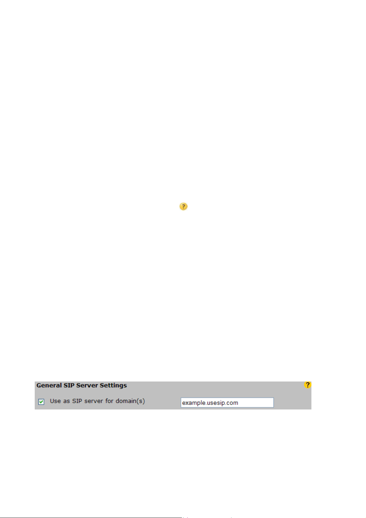
You configure your unit to act as a SIP server for your domain on the SIP Switch page, reachable
from the main menu of the web interface.
Enable Use as SIP server for domain(s) and enter the name of your domain! Then click Save.
You need to own the domain name you wish to use and the domain name needs to be translated to
the IP address of your unit by DNS.
Having done this, you can use SIP addresses like [email protected] for your SIP
clients and communicate with everyone else in the open SIP world!
- 16 -
Page 17
6.4 Creating Your Own SIP Domain
If you do not already own a domain name, you can easily get one at a domain name registrar found on
the web. Alternatively, you can directly select a sub domain of some predefined domain name at a
DNS service provider like Tekea or dyndns.org. Tekea, found at www.tekea.com provides special SIP
support, making it very easy to set up your own SIP domain.
To make your SIP server accessible, your SIP domain name has to be made available in DNS, e.g. by
your Internet service provider or by the mentioned DNS service providers.
If you have a fixed IP address, the domain name can be handled by a regular DNS server, but if you
have a dynamic IP address (allocated by your Internet service provider by DHCP - an address that
may vary from time to time) you need to use dynamic DNS.
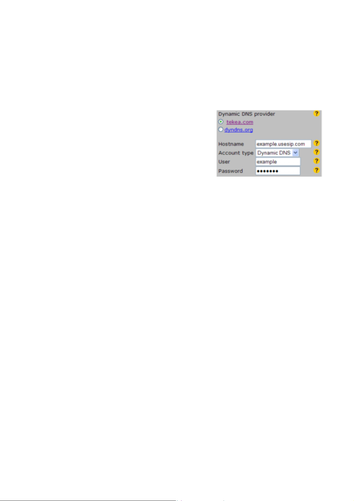
You can directly get a dynamic DNS account from Tekea or
dyndns.org, and should then use the dynamic DNS client in
your ADSL Internet Gate to keep your DNS entry updated.
From the main menu of your unit, select Network
Configuration, then Dynamic DNS. After having created a
dynamic DNS account at any of the listed Dynamic DNS
providers, you fill in the fields on the Dynamic DNS page.
Your ADSL Internet Gate will then update your dynamic DNS
account, whenever your IP address changes.
6.5 The SIP Switch
The SIP Switch is an additional software for your ADSL Internet Gate, that integrates the usage of soft PC
clients, SIP telephones and ordinary telephones, adds PBX functionality and gives a unique connectivity with the
old telephone network via common VoIP service provider’s SIP accounts.
You can learn more about the SIP Switch by clicking “Using SIP: Telephony, Video, Messaging” on
the login page of the web interface.
You purchase the SIP Switch software from the SIP Switch page of the ADSL Internet Gate. You can
also evaluate the SIP Switch for free for 10 days. The links for purchase and evaluate are found
beside the Dial Plan on the SIP Switch page.
Key functions of the SIP Switch are:
• Convenient dialling between SIP phones, soft SIP clients and ordinary analog telephones, using
URLs, E.164 numbers and internal “extension” numbers.
• Unlimited PSTN connectivity (in and out) through a simple VoIP provider account!
• Flexible Dial Plan (Setup wizard and downloadable examples to ease setup).
• Flexible and extensive ENUM lookup.
• Internal “extension” numbers, dial 0 (or 9) for outside.
• User accounts and User’s control page.
• Incoming regular phone calls are directly forwarded to the right user.
• Direct mapping to users of incoming PSTN calls.
• Forwarding, forking in parallel and sequence.
• Routing to Voice Mail servers requiring specifics in the request-URI.
• Restriction of incoming callers (Blacklist and/or Allow-list based on various criteria).
• Fallback functionality.
- 17 -
Page 18
7 Using the ADSL Internet Gate as an Analog
Telephone Adapter on the LAN
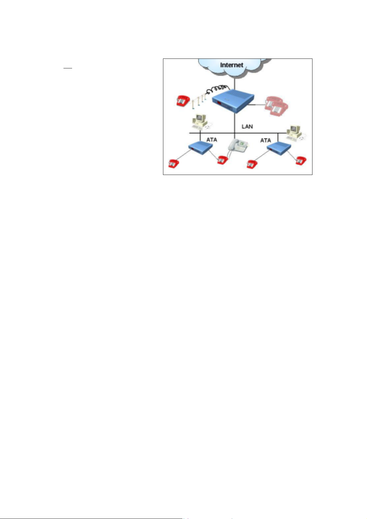
In some installations, the ADSL Internet
Gate may not be used as the Router/Firewall,
but instead as an Analog Telephone Adapter
(ATA-unit) connected to the LAN.
It is then important that the WAN port of
the ADSL Internet Gate is connected to
LAN.
Make sure that the address space used on
your LAN is not the same as the address
space used by the LAN Ethernet ports of the
ATA-units. If that is the case, before
connecting the ATA-unit to the LAN, you
need to go to the Network configuration
page of the ATA-units and change address
used by their LAN Ethernet ports.
Future firmware may add functionality to
simplify the configuration as an ATA-unit and also add useful functionality. Please check the Network
configuration page for such enhancements.
It is recommended that an ADSL Internet Gate also is used as the firewall and router for the LAN.
Thus, problems with firewalls and routers that do not handle SIP traversal are avoided.
8 Requirements
In order to set up and use your ADSL Internet Gate you need:
• A PC with an Ethernet port.
• A web browser such as the Microsoft Internet Explorer or the Netscape Navigator, version 4 or
later, installed on the PC.
• An RJ45 broadband Internet connection, from a wall connector, ADSL or Cable modem.
- 18 -
Page 19

END USER SOFTWARE LICENSE AGREEMENT
BY ENTERING INTO A BINDING AGREEMENT FOR THE PURCHASE, LEASE, HIRE OR OTHER USE OF
SOFTWARE, WHETHER OR NOT EMBEDDED IN PURCHASED HARDWARE, ALL AS SPECIFIED IN SUCH
AGREEMENT, AND WHERE THIS END USER SOFTWARE LICENSE AGREEMENT IS EITHER ATTACHED
TO SUCH AGREEMENT OR TO ORDER CONFIRMATION OR SIMILAR DOCUMENT SENT TO YOU ON OR
BEFORE DELIVERY, YOU HAVE AGREED TO THE TERMS OF THIS LICENSE AGREEMENT (NO LATER
THAN) UPON ACCEPTING DELIVERY.
1. THE LICENSE
INTERTEX Data AB, Rissneleden 45, 174 44 Sundbyberg, Sweden (“LICENSER”), authorizes you (the
“Licensee”) to use the software programs (the “Software”) specified in the purchase/lease/hire or similar
agreement (“the Purchase Agreement”) for the use of such Software, to which this License Agreement is
appended or otherwise connected, and/or which is embedded in hard ware equi pment specified in the Purchase
Agreement, and the Licensee accepts a non-exclusive, non-transferable License to "Use" (as hereinafter defined)
the Software on or connected to a single computer system (the "System") for use by the maximum number of
concurrent users and for the maximum number of concurrent sessions as specified in the Purchase Agreement,
upon the terms and subject to the conditions contained herein.
2. USE OF THE SOFTWARE
For the purposes of this License "Use" shall mean and include:
(i) utilization of the Software by copying, transmitting or loading the same into the temporary memory (RAM)
or installing into the permanent memory (e.g. hard disk, CD ROM or other storage device) of the System
for the processing of the System instructions or statements contained in such Software;
(ii) in the case of Software embedded in hardware equipment; by operating the hardware equipment;
(iii) storing the whole or any part of the Software on the System or other storage unit or disk;
(iv) utilizi ng (but not copying) the instructional and/or operational manuals relating to the Software.
For the purposes of this License "concurrent use" shall mean simultaneous use of the Software by the number of
users of the Licensee specified in the Purchase Agreement PROVIDED however that Software installed on a file
server for the sole purpose of distribution to other workstations or computers is not being Used for the purposes of
ascertaining the number of concurrent users.
3. LICENSEE'S UNDERTAKINGS
The Licensee may not perform any of the acts referred to in (i)-(iii) below except to the extent and only to the
extent permitted by the applicable law to the Licensee as a lawful user of the Software and only then for the
specific limited purpose stated in such applicable law or hereunder. Licensee may not
(i) copy the Software (other than for normal System operation) or otherwise reproduce the same
provided that the Licensee may copy the Software for back-up purposes;
(ii) translate, adapt, vary or modify the Software;
(iii) disassemble, decompile or reverse engineer the Software or any other action attempting to
discover or disclose the source code or the methods or concepts embodied in the sou rce co de
(iv) modify the software in any way so that copyrights, trademarks and other proprietary notices are
removed or altered
The Licensee further undertakes:
(v) not to provide or otherwise make available the Software in whole or in part (including where
applicable, but not limited to program listings, object code and source program listings, object
code and source code), in any form to any third party without prior written consent from
LICENSER;
(vi) within 14 days after the date of termination or discontinuance of this License for whatever
reason, to destroy the Software and all updates, upgrades or copies, in whole and in part, in any
form including partial copies or modifications of the Software received from LICENSER or made
in connection with this License, and all documentation relating thereto.
4. LIMITED WARRANTIES
Limited warranties are granted to the Licensee by the reseller of LICENSER products from which the Licensee
has purchased the Software, in accordance with a separate Warranty Statement attached to the Licensee’s
purchase agreement or to order confirmation or included in the delivery.
- 19 -
Page 20

5. LIMITATION OF LIABILITY
Without prejudice to the Licensee’s rights against the reseller according to a separate Warranty Statement as
provided in Section 4, the Licensee hereby acknowledges that software in general is not error-free and agrees
that the existence of such errors shall not constitute a breach of this License. THE SOFTWARE IS FURNISHED
AS IS AND LICENSER DISCLAIMS, TO THE EXTENT PERMITTED BY THE APPLICABLE LAW, ALL
WARRANTIES WITH RESPECT TO THE SOFTWARE, EITHER EXPRESS OR IMPLIED, INCLUDING BUT NOT
LIMITED TO ANY IMPLIED WARRANTIES OF MERCHANTABILITY, NON-INFRINGEMENT OR FITNESS FOR
ANY PARTICULAR PURPOSE.
LICENSER shall not be liable for any loss or damage whatsoever or howsoever caused arising dir ectl y or
indirectly in connection with this License, the Software, its use or otherwise, except to the extent that such liability
may not be lawfully excluded under the applicable law. Notwithstandin g the generality of the preceding sentence,
LICENSER expressly excludes liability for indirect, special, incidental or consequential loss or damage which may
arise in respect of the Software, its use, the System or in respect of other equipment or property, or for loss of
profit, business, revenue, goodwill or anticipated savings.
In the event that any exclusion contained in this License shall be held to be invalid for any reason and L ICENSER
becomes liable for loss or damage that may lawfully be limited, such liability shall be limited to the License fee
paid for the Software.
LICENSER does not exclude liability for death or personal injury to the extent only that the same arises as a result
of the negligence of LICENSER, its employees, agents or authorized representatives.
6. COPYRIGHT, PATENTS, TRADE MARKS AND OTHER INTELLECTUAL PROPERTY RIGHTS
The Licensee acknowledges that any and all of the copyright, trademarks, trade names, patents and other
intellectual property rights subsisting in or used in connection with the Software including all documentation and
manuals relating thereto are and remain the sole property of LICENSER or other third party where this is
specifically indicated. The Licensee shall not during or at any time after the expiry or termination of this License in
any way question or dispute the ownership by LICENSER.
7. TERMINATION
LICENSER may by notice in writing terminate this License if the Licensee is in breach of any term, cond ition or
provision of this License or required by the applicable law and fails to remedy such breach (if capable of remedy)
within 30 days of having received written notice from LICENSER specifying such breach. Termination, howsoever
or whenever occasioned shall be subject to any rights and remedies LICENSER may have under this Li cense or
under the applicable law.
- 20 -
Page 21

DECLARATION OF CONFORMITY
according to EN 45014
The manufacturer Intertex Data AB, Rissneleden 45, 174 44 Sundbyberg, Sweden, herewith declares
the firewalls/ADSL modems in the IX78, Powerbit Safegate and SurfinBird series are in compliance
with the essential requirements and other relevant provisions of the following EC directives:
1999/5/EC Radio & Telecommunications Terminal Equipment Directive (R&TTE)
and that the following harmonised standards and/or technical specifications have been applied:
Electromagnetic Emission: EN 61000-6-3:2001, EN 61000-6-3/A11:2004
- for units with WLAN EN 300 328
Electromagnetic Immunity: EN 55024:1998, EN 55024/A1:2001
Radio Electromagnetic Compatibility
- for units with WLAN EN 301 489-17
Safety: EN 60950-1:2001+A11:2004
- for units with WLAN EN50385:2002
Stockholm June 18, 2007
Karl Erik Ståhl, President Intertex Data AB
Customer Information for FCC Part 15
This device comply with Part 15 of the FCC Rules. Operation is subject to the following two conditions:
1. the devices may not cause harmful interference, and
2. the devices must accept any interference received, including interference that may cause
undesired operation.
NOTE: This equipment has been tested and found to comply with the limits for a Class B digital device,
pursuant to part 15 of the FCC rules. These limits are designed to provide reasonable protection
against harmful interference in a residential installation. This equipment generates, uses and can
radiate radio frequency energy and, if not installed and used in accordance with the instructions, may
cause harmful interference to radio communications.
However, there is no guarantee that interference will not occur in a particular installation. If this
equipment cause harmful interference to radio or television reception, which can be dermined by
turning the equipment off and on, the user is encouraged to try to correct the interference by one or
more of the following measures:
• Reorient or relocate the receiving antenna.
• Increase the separation between the equipment and receiver.
• Connect the equipment into an outlet on a circuit different from that to which the receiver is
connected.
• Consult the dealer or an experienced radio/TV technician for help.
Warning: Changes or modifications to this unit not expressly approved by the party responsibl e for
compliance could void the user authority to operate the equipment.
1. To comply with FCC RF exposure compliant requirements, a separation
distance of at least 20 cm must be maintained between the antenna of this
device and all persons.
2. This Transmitter must not be co-located or operating in conjunction with any
CAUTION:
other antenna or transmitter.
- 21 -
Page 22

Customer Information as required by ACTA according to FCC Part 68
1. This equipment complies with Part 68 of the FCC rules and the requirements adopted by the
ACTA. On bottom of this equipment is a label that contains, among other information, a product
identifier of US:IXDL01BIX78. If requested, this number must be provided to the telephone
company.
2. If this equipment US: IXDL01BIX78 ca uses harm to the telephone network, the telephone
company will notify you in advance that temporary discontinuance of service may be required. But
if advance notice isn’t practical, the telephone company will notify the customer as soon as
possible. Also you will be advised of your right to file a complaint with the FCC if you believe it is
necessary.
3. The telephon e company may make changes in its facilities, equipment, operations or procedures
that could affect the operation of the equipment. If this happens, the telephone company will
provide advance notice in order for you to make necessary modification to maintain uninterrupted
service.
4. If you experience trouble with this equipment, you should disconnect it from the network until the
problem has been corrected or until you are sure that the equipment is not malfunctioning.
5. Please do not alternate or repair any parts of this device.
6. Conne ction to party line service i s su bject to state tariffs. Contact the state public utility
commission, public service commission or corporation commission for information.
7. If the telephone company requests information on what equipment is connected to their lines,
inform them of:
a. The telephon e number that this unit is connected to
b. The ringer e quivalence number REN=0.1
c. The USOC jack required is RJ11C/W
d. The FCC Registratio n Number US: IXDL01BIX78
Item (b) and (d) are indicated on the label. The ringer equivalence number (REN) is used to
determine how many devices can be connected to your telephone line. In most areas, the sum of
the RENs of all devices on any one line should not exceed five (5.0). If too many devices are
attached, they may not ring properly.
8. If your home has spe cially wired alarm equipment connected to the telephone line, ensure the
installation of this equipment does not disable alarm equipment, consult your telephone company
or a qualified installer.
Service Requirements
In the event of equipment malfunction, all repairs should be performed by our Company or an
authorized agent. It is the responsibility of users requiring service to report the need for service to our
Company or to one of our authorized agents.
Service can be facilitated through our office at: Intertex, 12 Federal Lane, Dennis, MA 02638, USA,
Tel: (508) 385-6335
To preserve the environment, you should return the product to where you
purchased it or directly to an accredited electronics recycling station.
Intertex uses accredited companies and organisations for recycling and disposio n
of electronics, packing materials and emballage.
- 22 -
Page 23

This product is developed and manufactured by Intertex Data AB.
Copyright © 2007 Intertex Data AB
All rights reserved.
This manual and any associated artwork, software, and product designs are copyrighted with all
rights reserved. Under the copyright laws this manual, artwork, software, and product designs
may not be copied, in whole or part, without the written consent of Intertex. Under the law,
copying includes translation to another language or format.
Intertex Data AB
Rissneleden 45
SE-174 44 Sundbyberg
Sweden
Phone: +46 8 6282828
Fax: +46 8 628 64 14
Intertex
12 Federal
Dennis, Massachusetts 02638
United States
Phone: (508) 385-6335
Fax: (208) 474-0956
www.intertexdata.com
- 23 -
 Loading...