

Page 1

INT
EGR
INSTALLATION AND FIELD
MAINTENANCE MANUAL
AT
ED
TM
Part No. 440.8074
Issue
November 1994
Page 2
INSTALLATION AND FIELD
MAINTENANCE MANUAL
NOTICE
IMX
With the new 1995 North American Numbering Plan software releases, the
tical except for the station instruments that can be installed on them. To provide better service, condense reference
materials, streamline training, and facilitate technical support, the installation manuals for the two systems have been
combined into one generic manual.
When using this combined manual to help sell, install, or service a particular system, be aware that not all of the station
instruments described in this manual are available on both products. Listed below are the station instruments that can
be installed on each product.
IMX 256 Station Instruments
l Digital
l IMX AIM
l
l Attendant Computer Consoles
l Enhanced Single-Line Sets
GX
Digital
GX
Single-Line Instruments
Single-Line DTMF Sets
(including
(including “dual-circuit”
Units
Units
Units
GMX COMBINED INTO ONE MANUAL
256 and GMX-256 products are iden-
GMX-256 Station Instruments
GX
l Attendant Computer Consoles
GX
GMX Single-Line Instruments
.
Single-Line DTMF Sets
Units
Units
Units
Part No. 440.8074
Issue 1, November 1994
Page 3

Part Number
440.8074
INTEG
INSTALLATION AND
FIELD MAINTENANCE
Issue 1, November
RATED
TM
MANUAL
1994
@Inter-Tel Integrated Systems, inc. 1994
Printed in USA
Page 4
256 ISSUE 2
INDEX OF NEW FEATURES
For those individuals who are already familiar with the Issue 1 manuals for the
256 and GMX-256 Systems, the
following new items are documented in this combination manual. For complete information on each item, refer to the
page numbers following the brief explanation. Also, throughout the manual, %hange bars” like the one at the right
have been placed in the margins to indicate any new or revised information since the original manuals.
And GMX Combined Into One Manual
I
the new 1995 North American Numbering Plan software releases, the IMX 256 and GMX-256 products are
identical except for the station instruments that can be installed on them. To provide better service, condense reference materials, streamline training, and facilitate technical support, the installation manuals for the two systems
have been combined into one generic manual. When using this combined manual to help sell, install, or service a
particular system, be aware that not all of the station instruments described in this manual are available on both
products. See page 2-2 for a list of the station instruments that can be installed on each product.
North American Numbering Plan
The growth of telecommunications services has created an increasing demand for more telephone
meet the demand,
has prepared a long-range North American Numbering Plan (NANP) to provide addi-
numbers.
To
tional telephone numbers. The plan expands the capacity of the current numbering system by making area and
office codes interchangeable. That is, numbering patterns formerly reserved for office codes can be used as new
area codes and office codes within existing area codes can have the same pattern as other area codes. This version
of software supports the new numbering plan. See pages
Home And Local Area Codes
and 5-90.
In many areas, the telephone company has created call-cost arrangements that refer to “home” and “local” area
codes. The home area code is the area code within which the system resides. The local area codes are additional
area codes that, when called, use the local or toll local call-cost rate instead of the long distance rate. Up to three
local area codes can be programmed and then extended within toll restriction progxamming to provide proper call
Loop Start
Glare Protection
During a “glare” connection, the software now allows the incoming call to remain connected, while still protecting
against possible toll fraud. See pages 2-14 and
Station Exchange
This programmable station feature allows a station user to exchange the extension numbers of two station circuits.
This swaps the database and user programmed features of the extension numbers between two station circuits
without the need for database programming.The circuit number of the station locations are unchanged, but the
extension numbers are changed. See pages 4-99 and 5-31.
Digital Cards, Diil
and
Units
The IMX 256 System can now support the digital station instruments originally designed for the Inter-Tel Axxess
System. See pages
3-62 to
to
and 7-3.
All digital keysets utilize DSP shared resources for speakerphones, and Executive Digital Keysets have enhanced
displays. See pages 2-22,440, and 4-41.
APC Data Port Module (PCDPM) must be installed on digital keysets to provide the secondary voice path needed
for the
A
customer-provided, modem-equipped data device may be attached to any digital keyset with a PC Data
Module (PCDPM) and a Modem Data Port module (MDPM) installed. See pages
Feature And Speed-Dial Keys On
4-87, and 5-50.
feature. See pages
and 4-61.
Port
and 4-101.
Units
Page v
Page 5
INDEX OF NEW FEATURES (continued)
“Hot” Dial Pad Keys
There is a system-wide option that, if enabled, allows keyset users to dial line access codes and feature codes without lifting the handset or pressing the SPKR or SPCL key. This programmable feature is called “hot dial pad” to
indicate that the dial pad keys are always activated. See pages
Private Intercom Call Override
If a keyset station has the Private Intercom Override feature enabled, the user can place a
ing l or
When
when calling a keyset station that has handsfree mode disabled. See pages
Tone Selection
setting the ring tone on a keyset, the keyset user can enter 0 to disable ring tones. See page 4-48.
and 5-68.
call by press-
and 5-52.
Toll
The
Weekly Toll Limits:
cified types of toll calls. The feature can monitor 7- and
Set
software package now includes the following Toll Security features:
When enabled, the weekly toll limit feature keeps track of the accumulated call cost for spe-
toll calls and/or operator-assisted/international
calls. Alarm messages have been added for toll limit management. See pages
and 6-8.
Inter-Tel
Enhanced DISA
Services: The weekly toll limit feature can only be enabled by Inter-Tel Services. See page 6-41.
Codes: DISA security codes can be 4-7 digits long. ADISA caller will have only three
opportunities to enter a valid security code. If the caller fails three times, the failure will generate a system alarm
and that trunk will be inoperable for five minutes. See pages
DISA Toll Restriction:
DISA lines can be given day and/or night mode toll restrictions like those for individual
stations (except LCR-Only). See pages
SMDR Blocked DISA
Calls
Option:
A programming flag has been added to SMDR that allows blocked DISA
calls to appear in the Sh4DR report. See pages
DISA And Hunt Group
SMDA Summary Reports
and 5-116.
and 4-124.
and 6-8.
information has been added to the System Summary report and a new Hunt Croup option has been added
to the Summary Report. See pages
End-Of-Dialing Digit Suppression
Display and Redial: A system
programmin g flag allows the programmer to specify whether all dialed digits or
and 5-140.
just the digits that make up the valid call are displayed and stored in the redial buffer. If desired, the “extra” digits
used for dial-up banking machine, voice mail, automated attendant, or other purposes
suppressed. Suppressing the extra digits prevents entries, such as PIN numbers and other codes, from being displayed when they are
dialed. See pages 4-93 and 5-69.
A programming flag has been added to the
programming prompts that allows you
to specify whether all dialed digits or just the digits that make up the valid call appear in the SMDR report. See
pages 4-123 and 5-142.
Account Code Enhancements
Toll Forced Account
LCR-Only toll restriction in day
Code: Forced account codes for toll calls only can be programmed for stations with
night modes. When this account code type is enabled, the user only has to
enter an account code if the system detects that a toll call has been dialed
5-32, and 5-55.
Validated Forced Account
Codes: Forced account codes can be validated or non-validated. See page 4=-66,5-32,
5-33, and 5-55.
Page vi
is used. See pages
Page 6
INDEX OF NEW FEATURES (continued)
Voice Mail/Computer Enhancements
Do-Not-Disturb Breakthrough:
computer are not blocked by placing the station in do-notdisturb. If desired, individual stations can be set to pre-
vent these calls from breaking through do-not-disturb. See pages
Voice Mail/Computer Hunt
designated as a voice computer hunt group. See pages
Automated Attendant Hunt Groups: Voice computer hunt groups can be designated as automated attendant
hunt groups. See pages 4-21 and 5-63.
Dial RuleS:
Recall Destination:
and 5-64.
tions. See page 5-66.
DTMF Feedback Tones:
tones that determine call status. See pages
the “extended” set of feedback tones can also be enabled
Allow Cross-Tenant Voice Mail/Computer
and voice mail computers will be allowed to place intercom calls, forward intercom calls, or transfer intercom or
outside calls to stations that are in different tenant groups. See pages 4-21 and
Version Feature
Code: When entered at a voice computer port this feature code generates a four-digit IYIMF
code that indicates the last four digits of the software part number. It is used by voice processing software to ensure
that the
software is compatible with the voice pro&sing features. See page 4-7.
Normally, calls to a station through
the automated attendant, or a voice
and 5-52.
Groups
All
Software Packages:
In any software package, any hunt group can be
S-61, and 5-62.
mail/computer hunt group can have an assigned recall destination. See pages 4-21
Stations:
Voice mail/computer hunt groups can serve as overflow/announcement sta-
The progress tones that are normally sent to a voice computer can be replaced with
and 5-52. If feedback tones are enabled,
system-wide programming. See pages 5-67 and 5-68.
The Programmer can determine whether voice mail units
Remote Hunt Group Remove/Replace
The Hunt Group Remove/Replace feature can be controlled from the attendant’s station using the Remote Hunt
Group Replace feature code. See pages
Hunt Group Enhancements
There is a system option that can be enabled to send
and 4-111.
unanswered hunt group calls first to the announcement
station and then to the overflow station. See pages 4-17 and 5-68.
If a station that receives a recalling hunt group call chooses to transfer the call back to the hunt group, the call
retains its original queue position in the hunt group. Also, calls that go to the announcement and overflow stations
do not lose their places in the queue. While the call is at a playback device announcement or overflow station
(except voice compufer overflow/announcement stations) it continues to circulate through the hunt group. If a
hunt group member picks up the call, it is pulled back from a playback device overflow/announcement station and
connected to the hunt group station. See pages 4-18 and 4-19.
Station Off-Hook Alarm
The STXlTON OFF HOOK alarm now indicates the station that is off hook. Also, the alarm clears automatically
when the station user hangs up. See pages
Equal Access
The system supports the
Numbers Supported
and “1OXXX” equal access numbers. Toll restriction SCOS 7 has also been
modified to support equal access dialing. See pages
Password Required
and 6-8.
and 5-88, and 5-113.
The password prompt will always appear when a programmer logs in to a programming session. In the default state
there is no database programming password and pressing
RETURN will allow access to the database. See page
5-10.
Page 7
256
MAINTENANCE
TABLE OF CONTENTS
TABLE OF CONTENTS
Issue 1, November
PAGE
INDEXOFNEW FEATURES
TABLE OF CONTENTS
LIST OF FIGURES
FCC REGULATIONS
.....................................................
...................................................
SAFETY REGULATIONS
LIMITED WARRANTY
............................................
.................................................
...............................................
.................................................
...........................................................
1. Introduction ........................................................
2. System Capacities ....................................................
3. Software Packages ...................................................
4. Hardware Summary
5. Installation, Programming, And Maintenance Summary
6. Features Summary ...................................................
SPECIFICATIONS
1. Introduction ........................................................
2. Cabling And The Main Distribution Frame
3. Equipment Cabinet ...................................................
4. Station Instruments
5. Additional System Equipment
..................................................
......................
.....................................................
..........................
...................................................
..........................................
V
ix
...
xvii
l-l
l-l
l-l
1-2
l-3
1-3
1-4
2-l
2-2
2-4
2-6
2-21
2-31
INSTALLATION
1. Introduction ........................................................
2. System Installation Outline ............................................
3. Pre-Installation Checklist
4. Station Cabling ......................................................
5. Assembling The Main Distribution Frame
6. Equipment Cabinet Installation
7. Station Installation
8.
9. External Paging Equipment Installation
10. External Music Source Installation
11. Preventative Maintenance
12. Post-Installation Checklist
. . . . . . . . . . . . . . . . . . . . . . . . . . . . . . . . . . . . . . . . . . . . . . . . . . . . . . .
..............................................
Backboard
.........................................
...................................................
Output Device Installation
.......................................
..............................................
.............................................
................................. 3-98
...................................
................. 3-9
3-1
3-2
3-2
3-3
3-6
3-35
3-62
3-98
3-99
3-99
3-100
Page ix
Page 8
Issue 1, November 1994
OF CONTENT!3
INSTALLATION
MAJNTENANCE
CONTENTS
FEATURES
1. Introduction
2. Accessing The Features
3. System Organization
4. Tnmk Features
5. Station Instruments
6. User-Programmable Feature Keys
7. Automatic Call Access (Keysets Only)
8. Music-On-Hold And Background Music
9. Signals And Tones
10. Intercom Galls
11. Inter-Station Messages
12. Off-Hook Voice Announce (OHVA)
13. Outside Galls
14. Placing Calls On Hold
15. Call Waiting
16. Call Transfer
17. Reverse Transfer And Group Call Pick-Up
18. Call Privacy And Privacy Release
19. Barge (Keysets Only)
20. Conference Galls
21. System Forwarding
............................................................
........................................................
...............................................
..................................................
......................................................
...................................................
.......................................
...................................
..................................
...................................................
.......................................................
................................................
.....................................
........................................................
................................................
........................................................
........................................................
.................................
.......................................
.................................................
.....................................................
...................................................
22. Call Forwarding .....................................................
23. Speed Dialing
24. Optional System Directory
25. House Phone
.......................................................
Intercom And Outside (Keysets Only)
...........
........................................................
26. Redialing ...........................................................
27. Paging
28. Remove From Paging
29. Do-Not-Disturb
30. Cancel Miscellaneous Operations
31. Hookflash
32. Reminder Messages (Keysets Only)
33. Optional Station Exchange Feature
34. Optional Data Device Attachments (Keysets Only)
35. Attendant Features
36. Record Keeping And Maintenance Features
.............................................................
.................................................
......................................................
........................................
..........................................................
......................................
......................................
..........................
...................................................
...............................
PAGE
4-4
4-4
4-12
4-24
4-40
4-51
4-52
4-53
4-54
4-55
4-58
4-61
4-62
4-67
4-69
4-70
4-73
4-74
4-75
4-76
4-79
4-82
4-85
4-90
4-92
4-93
4-94
4-94
4-95
4-97
4-97
4-98
4-99
4-101
4-103
4-114
Page x
Page 9

256
& MAINTENANCE
TABLE OF CONTENTS
Issue 1, November 1994
CONTENTS
PROGRAMMING
1. Introduction
2. System Set-Up For Programming
3. Session Timer And Screen Saver
4. Microsoft Windows
5. How To Use The Programming Windows
6. Applications Menu
7.
Values
8. Station Programming
9. Station Programming
10. System-Wide Features
11. Toll Restriction
12. Least-Cost Routing @CR)
13. Trunk Programming
14. Attendants
15. Station Message Detail
16. Service
.............................................................
......................................................
........................................................
.......................................
........................................
..................................................
.................................
...................................................
.......................................................
Individual Station Information
Batch Programming Options
................................................
......................................................
.............................................
..................................................
..........................................................
................................................
......................
.......................
PAGE
5-l
5-3
5-3
5-11
5-11
5-12
5-15
5-24
5-25
5-44
5-54
5-88
5-98
5-103
5-132
5-137
5-145
TROUBLESHOOTING
1. Introduction
........................................................
2. Troubleshooting Checklist
3. Light-Emitting Diode (LED) Indications
4. Alarm Messages And Field Service Diagnostics
5. Troubleshooting Charts
6. Customer Support
7. Defective Unit Return Policy
REPLACEMENT PARTS
1. Introduction
........................................................
2. Ordering Procedure
3. Replacement Parts List
4. Recommended Spare Parts
.................................................
.............................................
..................................
............................
................................................
....................................................
...........................................
................................................
...................................................
................................................
.............................................
APPENDIX A- GX STATION INSTRUMENTS
1. Overview.
2. Specifications
3. Installation
4. Features
5. Programming
..........................................................
.......................................................
.........................................................
............................................................
.......................................................
...........................
6-l
6-l
6-l
6-l
6-8
6-12
6-41
6-41
7-l
7-l
7-l
7-l
7-1
A-l
A-l
A-l
A-4
A-10
A-10
Page xi
Page 10

Issue 1, November
OF CONTENTS
INTER-TELPRACTICES
256 INSTALLATION
MAINTENANCE
APPENDIX B
1. Overview
GMX STATION INSTRUMENTS
. . . . . . . . . . . . . . . . . . . . . . . . . . . . . . . . . . . . . . . . . . . . . . . . . . . . . . . . . . .
. . . . . . . . . . . . . . . . . . . . . . . . . .
2. Specifications . . . . . . . . . . . . . . . . . . . . . . . . . . . . . . . . . . . . . . . . . . . . . . . . . . . . . . .
3. Installation . . . . . . . . . . . . . . . . . . . . . . . . . . . . . . . . . . ..*............*.......
4.
Features
. . . . . . . . . . . . . . . . . . . . . . . . . . . . . . . . . . . . . . . . . .
5. Programming
. . . . . . . . . . . . . . . . . . . . . . . . . . . . . . . . . . .
. . . . . . . . . . . . . . . . . .
. . . . . . . . . . . . . . . . . . . .
INDEX
B-l
B-l
B-l
B-5
B-10
B-10
I-l
Page xii
Page 11
SPECIFICATIONS
MAINTENANCE Issue 1, November
LIST OF
Figure 2-l.
Figure 2-2.
Figure 2-3.
Figure 2-4.
Figure
Figure 2-6.
Figure 2-7.
Figure 2-8.
Figure 2-9.
Figure 2-10.
Figure 2-11.
Figure 2-12.
Figure 2-13.
Figure 2-14.
Figure 2-15.
Figure 2-16.
Figure 2-17.
Figure 2-18.
Voice Channel Allocation
Digital AC Transformer Requirements
Executive Digital Keyset (also called Executive Digital Terminal)
Standard Digital Keyset (also called Standard Digital Terminal)
IMX 24-Line AIM Keyset
IMX
IMX
AIM
IMX 8-Line Keyset
IMX 8-Line AIM Keyset
Inter-Tel/DVK
....................................
.........................
........................................
....................................
........................................
....................................
.........................................
.....................................
Keyset
................................
................................
....
......
.................................
Digital Direct Station Selection/Busy Lamp Field (DSS/BLF) Unit
...
........................................
.................................
Enhanced Single-Line Set (ESLS)
Single-Line Instrument (SLI)
.............................
.................................
2-7
.
2-24
2-33
2-34
I
2-35
2-36
2-37
2-38
2-39
2-40
2-41
2-42
2-43
I
2-45
2-46
2-47
2-48
INSTALLATION
Figure 3-l.
Figure 3-2.
Figure 3-3.
Figure 3-4.
Digital Keyset Modular Jack Assembly Wiring
Analog Station Modular Jack Assembly Wiring
Sample MDF Block Layout And Cable Assignments
Example Of Ferrite Bead Installation
Figure 3-5.
Figure 3-6.
Figure 3-7.
Figure 3-8.
IDC Block Cable Terminations
EMC Block Cable Terminations
Figure 3-9.
Figure 3-10.
Modular Jack Assembly Wiring For
Figure 3-11.
Figure 3-12.
Figure 3-13.
Figure 3-14.
Using The
Digital KSC Block Cable Terminations For Keysets
Analog KSC Block Cable Terminations
...........................
................................
...............................
Span Terminations From RJ48C Jacks
.......................
Spans
Span Terminations From RJ-Type Blocks
Card’s Optional DB15 Connector
.........................
Page xiii
...................
...................
...............
.................
.................
....................
.....................
..................
...............
3-7
3-8
3-10
3-12
3-13
3-14
3-15
3-16
3-18
3-18
3-19
3-20
3-22
3-23
Page 12
LIST
Issue 1, November
256
INTER-TELPRACTICES
Figure 3-15.
Figure 3-16.
Figure 3-17.
Figure
3-18.
Figure 3-19.
Figure 3-20.
Figure 3-21.
Figure 3-22.
Figure 3-23.
Figure 3-24.
Figure 3-25.
Figure 3-26.
Figure 3-27.
Figure
3-28.
Figure 3-29.
Figure 3-30.
Figure 3-31.
TITLE
Installing &Line IMX AIM Keysets Two To A Circuit
KSC-D Block Cable Terminations For Dual-Circuit Keysets
SLC Block Cable Terminations
IDC Block Cable Terminations
................................
................................
Station Cable Terminations On The Station Block
RCPU Card Cable Terminations
Modular Jack Assembly Wiring For Optional
Connecting Two
Cards Together
...............................
Alarm Relays
.............................
Power Cable Connectors On The Telecom Motherboard
Connecting The Power Cable To The Telecom Motherboard
Cable Connections To The Power Supply Chassis
Power Supply Module Installation
Equipment Cabinet Grounding
.............................
................................
Power Supply Connector Pinouts And Voltage Test Point Locations
RCPU Card
Digital Keyset Card (DKSC)
...............................................
..................................
.............
.........
.................
......
............
.........
.................
...
................................
3-24
3-25
3-26
3-27
3-28
3-31
3-33
3-34
3-36
3-37
3-38
3-40
3-41
3-43
3-46
3-48
3-50
Figure
3-32.
Figure 3-33.
Figure 3-34.
Figure 3-35.
Figure 3-36.
Figure 3-37.
Single-Line Card (SLC)
Inward Dialing Card (IDC)
Loop/Ground Start Card (LGC)
Loop Start Card
E&M Card (EMC)
Card
..........................................
...........................................
Standard Digital Keyset LCD Installation.
Digital Keyset Self-Test Key Matrix
Digital PC Data Port Module (PCDPM) Installation
Sample Digital PCDPM Cable Connections
I
Figure Figure Figure Figure Figure 3-38. 3-39. 3-40. 3-41. 3-42.
Figure 3-43.
Figure 3-44.
Digital Modem Data Port Module (MDPM) Installation
IMX 24/12-Line Keyset LCD Installation
Bottom Of 8-Line Dual-Circuit IMX AIM Keyset
Figure 3-45.
Figure
3-46.
Figure 3-47.
IMX Keyset
Inter-Tel/DVK
Set-Up
Figure 3-48.
Figure 3-49.
Figure 3-50.
Inter-Tel/DVK Data Port Module Installation
Set-Up
.....................................
...................................
...............................
......................................
.......................
............................
...............
......................
............
.......................
.................
......................
....................................
Keyset “Large” LCD Installation
...........
.........
.....................
..................................
3-52
3-53
3-55
3-56
3-58
3-60
3-63
3-65
3-68
3-69
3-70
3-72
3-76
3-79
3-80
3-82
3-84
3-88
3-89
Page xiv
Page 13
LIST OFFIGURES
Issue 1. November 1994
TITLE
Figure 3-51. Back Of Digital DSS/BLF Unit
........ .......................
Figure 3-52. Inter-Tel/DVK DSS/BLF Unit Control Board
Figure 3-53.
Figure 3-54. Bottom Of ESLS
Figure 4-l.
Figure 4-2.-
Figure 4-3.
Figure 4-4.
Figure 4-5. SMDR Report Format
PROGRAMMING
Figure 5-1.
Figure 5-2.
Figure 5-3.
Figure 5-4.
Figure 5-5.
Figure 5-6.
Figure 5-7.
Figure 5-8.
Figure 5-9.
Figure 5-10.
Figure 5-11.
Figure 5-12.
Figure 5-13.
Figure 5-14.
Figure 5-15.
Figure 5-16.
Figure 5-17.
Figure 5-18.
Figure 5-19.
Figure 5-20.
Figure 5-21.
Figure 5-22.
Figure 5-23.
Figure 5-24.
SLI Control Board
Span Applications
SMDA Account Code Report Format
SMDA Summary Report Format
SMDA Detailed Report Format
................. .........................
..............
........
.............................
...............................
...........................
..........
...............................
.......................................
Applications And Programming
Customized Programming Report Samples
............ ................
......................
Sample Board-To-Voice Bus Mapping Report
Individual Station Programming (STN)
Key Assignments (KEY)
.....................................
Ring Zone Programming (ZONE)
Station Features (SFEA)
Account Codes (ACCI’)
.....................................
........ ........ .....................
.........................
....... ......................
Do-Not-Disturb And Reminder Messages (MESG)
Extensions, Usernames, And Feature Codes (EXT)
Hunt Groups (HUNT)
Misc. System-Wide Information (MISC)
Page Zones (PAGE)
Relays @LAY)
System Forwarding Paths (SFWD)
System Speed Dial (SSPD)
System Timer (TIMR)
Tenant Groups (TNT)
Carriers And Allowed Long Distance (ALT)
.......................................
........................
.................................. .......
............................................
.............................
...................................
.......................................
.......................................
.....................
Area/Office Code Restriction User Groups (AREA)
Station Class Of Service/LCR Advances (SCOS)
Toll Security (TOLL)
Least-Cost Routing (LCR)
Individual Trunk
Trunk Groups, Did Groups
............ .........
........ ...........................
.....................................
....................
....................
....................
................
................
...............
.................
..................
Patterns (TRNK)
.....
PAGE
3-91
3-94
3-96
3-97
4-36
4-117
4-118
4-120
4-124
5-124
5-156
5-173
5-174
5-177
5-188
5-189
5-190
5-195
5-197
5-202
5-203
5-204
5-204
5-205
5-206
5-207
5-210
5-211
5-212
5-213
5-216
5-217
5-223
5-224
Page xv
Page 14
OFFIGURES
Issue 1, November 1994
NUMBER TITLE PAGE
256
MAINTENANCE
Figure 5-26.
Figure S-27. Attendants
Figure 5-28. Attendants
Figure 5-29. Call Cost (COST)
Figure S-30. SMDA (SMDA)
Figure 5-31. SMDR (SMDR)
Figure S-32. Error Reports (ERR)
Figure 5-33. Passwords (PASS)
Figure 5-34. Serial Port Configuration (PORT)
Figure 5-35.
Programming
....................................... 5-227
Alias Programming (ALSS)
DSWBLF Units (DSS)
..........................................
...........................................
............................................
........................................ 5-233
..........................................
System Configuration (CONF)
.......................
...........................
..............................
................................
TROUBLESHOOTING
Figure 6-1. Light-Emitting Diode (LED) Indications
Figure 6-2.
Figure 6-3. CO Trunk Troubleshooting Chart
Figure 6-4. Feature Troubleshooting Chart
Figure 6-5. Keyset Troubleshooting Chart
System Troubleshooting Chart
................................
................................
.................................
..............................
Figure 6-6. Single-Line Set Troubleshooting Chart
Figure 6-7. DSS/BLF Unit Troubleshooting Chart
........................
..........................
..........................
5-228
5-229
5-230
5-231
5-232
5-233
5-234
5-235
6-3
6-14
6-18
6-24
6-30
6-36
6-39
REPLACEMENTPARTS
Figure 7-l.
Replacement Parts
. . . . . . . . . . . . . . . . . . . . . . . . . . . . . .
Figure 7-2. Recommended Spare Parts
APPENDIX A
Figure A-l.
Figure A-2.
Figure A-3.
Figure A-4. Key Assignments (KEY)
GX 24-Line Keyset
GX Keyset Bottom
......................................... A-3
......................................... A-5
GX DSS/BLF Unit Bottom
.....................................
APPENDIX B
Figure B-l.
Figure B-2.
Figure B-3.
Figure B-4.
Figure B-5.
GMX 24-Line Keyset
GMX
GMX 24-Line Keyset Data Port Module Installation
GMX DSS/BLF Unit Bottom
Key Assignments (KEY)
....................................... B-3
....................................... B-4
.....................................
. . . . . . . . . . . .
7-l
. . . . . . . . . . . . . . . . . . . . . . . . . . . . . . . . . . . 7-5
...................................
A-9
A-11
............... B-7
................................. B-9
B-11
Page xvi
Page 15
MAINTENANCE
FCC REGULATIONS
Issue 1,
November 1994
FCC REGIJIAI’IONS
IMPORTANT:
1.
This equipment complies with Part 68 of FCC rules.
On the back of the equipment cabinet is a label that
contains, among other information, the FCC registration number and ringer equivalence number
for this equipment. Customers connecting
this equipment to the telephone network shall, before such connection is made, give notice to the tele-
phone company of the particular line(s) to which
such connection is to be made, and shall provide the
telephone company with the following information:
Complies with Part 68 of FCC rules
FCC registration number:
MF-E (for MF-rated systems) or
(for KF-rated systems)
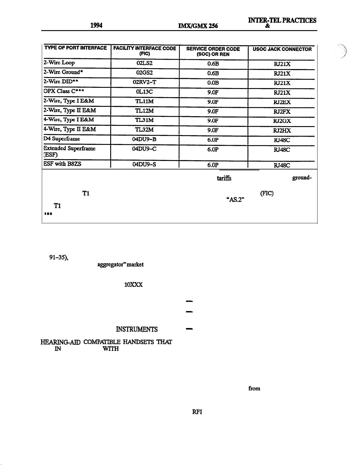
Quantities and USOC numbers of required inter-
face jacks (see chart on next page)
Sequence in which trunks are to be connected
equivalence number
der code
chart on next page)
NOTE: The
tity of devices which may be connected to the
telephone line. Excessive RENs on the telephone
line may result in the devices not ringing in re-
sponse to an incoming call. In most, but not all
areas, the sum of the RENs should not exceed
five (5.0). To be certain of the number of devices
that may be connected to the line, as determined
by the total RENs, contact the telephone company to determine the maximum
ing area.
as applicable, by position (see
is used to determine the quan-
or service or-
for the call-
tion to party line service is subject to state
(Contact the state public utility commission, public
service commission, or corporation commission for
information.)
3.
If this equipment causes harm to the telephone network, the telephone company will notify the customer in advance that service may be temporarily
discontinued. But if advance notice is not practical,
the telephone company will notify the customer as
soon as possible. Also, the customer will be advised
of the right to file a complaint with the FCC, ifneces-
4.
The telephone company may make changes in its fa-
cilities, equipment, operations, or procedures which
may affect the operation of this equipment. If so, the
customer shall be given advance notice so that any
necessary modifications can be made in order to
maintain uninterrupted service.
5.
If trouble is experienced with this equipment, contact a local authorized factory service representative
for repairs and/or warranty information. The cus-
tomer, users, and unauthorized technicians should
not repair, make adjustments to, or attempt to service this equipment in any way.
In the event of trouble with the telephone line(s), this
equipment must be disconnected from the telephone
line(s). If trouble ceases, the equipment must be repaired by an authorized factory service representative. If the trouble continues to occur with the
equipment disconnected, the telephone company
should be notified that they have a problem. If this is
the case, repairs or adjustments made by the telephone company will be made at their expense.
Facility interface code
chart on next page)
The telephone company should also be given notice
upon final disconnection of this equipment from the
particular line(s).
It is also the responsibility of the customer to provide
the telephone company with registration numbers of
any other devices which are configured for connection to the telephone network.
2.
This equipment cannot be used on public coin service provided by the telephone company. Connec-
by position (see
6.
Page xvii
Allowing this equipment to be operated in such a
signaling is in violation of Part 68 of FCC rules. This
equipment returns answer supervision signals to the
public telephone network when: answered by the
called station, answered by the attendant, routed to a
recorded announcement that can be administered by
the equipment user, and routed to a dial prompt. This
equipment also returns answer supervision on all
DID calls forwarded back to the public telephone
network. Permissible exceptions are: a call is unanswered, busy tone is received, and reorder tone is received.
Page 16
FCC REGULATIONS
Issue 1, November
INSTALLATION
MAINTENANCE
* Available with MF-rated systems only. According to FCC regulations, tar%& do not permit the use of ground-
start facilities with RF-rated systems.
* *
When using
instead, provide the telephone company with DID answer supervision code
facilities to provide DID service, do not use the DID facility interface code (FIG) as listed above;
and the FIC for the requested
service.
Also interfaces with Class A and B.
7.
This equipment does not currently comply with the
amended Part 64 of FCC rules (CC Docket No.
which requires that equipment sold and
installed in the “call aggregator”market (i.e., hotels,
motels, hospitals, universities, etc.) must allow users
equal access to the long distance carriers of their
choice (i.e., must allow the
dialing sequences normally used for “operator-assisted” calls,
while blocking those normally used for ‘direct-dial”
calls). In the future, this equipment may be modified
to comply with this requirement.
NOTICE: THE TELEPHONE
SPE-
CIFICALLY DESIGNED FOR THIS SYSTEM HAVE
ARE
COMPLIANCE
SECTION 68.316 OF
THE FCC RULES.
WARNING:
This equipment generates and uses radio
frequency energy and if not installed and used properly,
that is, in strict accordance with the manufacturer’s
instructions, may cause interference to radio and television reception. It has been type tested and found to com-
ply with the limits for a Class A computing device in
accordance with the specifications in Subpart J of Part
15 of FCC Rule. Operation of this equipment in a residential area may cause unacceptable interference to ra-
dio and TV reception requiring the operator to take
whatever steps are necessary to correct the interference.
However, there is no guarantee that interference will not
occur in a particular installation. If this equipment does
cause interference to radio or television reception,
which can be determined by turning the equipment off
and on, the user is encouraged to try to correct the interference by one or more of the following measures:
Reorient the receiving antenna
Relocate the equipment cabinet with respect to the
receiver
Check that the equipment cabinet and receiver are
not on the same circuit; the equipment cabinet must
be powered from an isolated, dedicated AC outlet
If necessary, the user should consult the dealer or an experienced radio/television technician for additional
suggestions. The user may find the following booklet
prepared by the FCC helpful: “How to Identify and Resolve Radio-TV Interference Problems”
This booklet is available
the U.S. Government
Printing Office, Washington, D.C. 20402, Stock No.
-398-5.
If
problems persist, contact Inter-Tel Customer
support.
Page xviii
Page 17
INTER-TELPRACTICES
256
Issue 1, November 1994
The Inter-Tel
listed by Communication Certification Laboratory
(CCL) as meeting the Product Safety Requirements
of UL 1459, Standard for Telephone Equipment.
CCL is approved by the Occupational Health and
Safety Administration
Recognized Testing Laboratory
installation, also check the local
for importalrt information concerning the irzstalla-
tion of telephone and electronic quipment.
The following safety information is reprinted from UL
1459.
and GMX 256 Systems are
as a Nationally
codes
IMPORTANT SAFETY
INSTRUCTIONS
When using your telephone equipment, basic safetypre-
cautions should always be followed to reduce the risk of
fire, electric shock, and injury to persons, including the
following:
1. Read and understand all instructions.
2.
Follow all warnings and instructions marked on the
product.
3. Unplug this product
cleaning. Do not use liquid cleaners or aerosol
cleaners. Use a damp cloth for cleaning.
4. Do not use this product near water (for example, in a
wet basement).
5.
Do not place this product on an unstable cart, stand,
or table. The product may fall, causing serious damage to the product.
6. Slots and openings in the cabinet and the back or
bottom are provided for ventilation, to protect it
from overheating; these openings must not be
blocked or covered. This product should never be
placed near or over a radiator or heat register. This
product should not be placed in a built-in installa-
tion unless proper ventilation is provided.
7. This product should be operated only from the type
of power source indicated in the manual. If you are
not sure of the type of power source to your building, consult your dealer or local power company.
8. This product is equipped with a three-wire grounding type plug, a plug having a third (grounding) pin.
This plug will only fit into a grounding type power
outlet. This is a safety feature. If you are unable to
insert the plug into the outlet, contact your electri-
the wall outlet before
cian to replace your obsolete outlet. Do not defeat
the safety purpose of the grounding type plug.
9.
Do not allow anything to rest on the power cord. Do
not locate this product where the cord will be
abused by persons walking on it.
10. Do not use an extension cord with this product’s
power cord. The AC outlet for this product should
not be used for any other electrical equipment.
11. Never push objects of any kind into this product
through cabinet slots as they may touch dangerous
voltage points or short out parts that could result in a
risk of fire or electric shock. Never spill liquid of
any kind on the product.
12. To reduce the risk of electric shock, do not disas-
semble this product, but take it to a
serviceman when some service or repair work is required. Opening or removing covers may expose
you to dangerous voltages or other risks. Incorrect
reassembly can cause electric shock when the product is subsequently used.
13. Unplug this product from the wall outlet and refer
servicing to qualified service personnel under the
following conditions:
A.
When the power supply cord or plug is dam-
aged or frayed.
B. If liquid has been spilled into the product.
C. If the product has been exposed to rain or wa-
ter.
D. If the product does not operate normally by fol-
lowing the operating instructions. Adjust only
those controls that are covered by the operating
instructions because improper adjustment of
other controls may result in damage and will
often require extensive work by a qualified
technician to restore the product to normal op-
eration.
E. If the product has been dropped or the cabinet
has been damaged.
If the product exhibits a distinct change in per-
formance.
14. Avoid using a telephone (other than a cordless type)
during an electrical storm. There may be a remote
risk of electric shock from lightning.
15. Do not use the telephone to report a gas leak in the
vicinity of the leak.
AC
SAVE THESE
INSTRUCTIONS
Page xix
Page 18
For a period of one (1) year from the date of shipment to
Buyer, INTER--TEL warrants the Equipment (except for
fuses and lamps) to be free
workmanship, or both, and to comply with specifications for the Equipment, as set forth in the
and
clusive remedy for breach of this Limited Warranty
shall be to have the defective Equipment (or parts) repaired or replaced at INTER-TEL% option. Shipping
costs incurred returning warranty work to INTER-TEL
shall be paid for by the Buyer.
Equipment (or parts) damaged by improper handling,
normal wear and tear, accidents, lightning damage, neg-
ligence, or improper use or maintenance, and does not
apply to Equipment altered without authorization by
INTER-TEL. This Limited Warranty does not extend to
any claims, suits, damages, liabilities, costs, and expenses arising from any act, action, or inaction of Buyer.
Although the Moss-Magnuson Act should not apply, in
the event that it is held to apply by a court of competent
jurisdiction, the implied warranty of fitness for a par-
ticular purpose shall extend for the one-year (l-year)
period from the date that the Equipment was shipped to
the Buyer.
to the Buyer,
This Limited Warranty does not apply to
defects in material,
Buyer’s sole and ex-
This Limited Warranty
any customer, user, or
ZN
ALL OTHER
OF
FOR A
WZiZZCHEXTEND
BE
LOSS OF
BUYER
POSSESSION,
For complete information on returning equip
turn
This document includes specific information on
the following subjects: warranty, procedures to
follow when returning equipment, equipment
damaged in shipment, insurance, repair policy,
and advance replacement policy.
FOR LOSS OF
OR CONSEQUENTIAL
SUCH
BY THE
Policy
PURPOSE.
OR OTHER LOSSES ZNCUZMED BY
(document part number 835.1065).
OF AND EXCLUDES
EXPRESS OR ZiUPKlED,
OR
PROFZl3,
THE PURPOSE,
OR USE OF
NO
Re-
Page xx
Page 19
256
MAINTENANCE
Issue 1, November
OVERVIEW
1. Introduction ..........................................................
2. System Capacities .....................................................
3. Software Packages
....................................................
4. Hardware Summary ...................................................
5.
Installation, Programming, And Maintenance Summary
....................
6. Features Summary ....................................................
. System Features ...................................................
B.
C. Enhanced Single-Line Set (ESLS) Features
D. Single-Line Instrument
Features ...................................................
............................
Features ................................
E. Direct Station Selection/Busy Lamp Field (DSS/BLF) Unit Features
.
Attendant Computer Console Features
G. Attendant Features
................................................
................................
H. Maximum Capacities ..............................................
1. INTRODUCTION 2. SYSTEM CAPACITIES
1.1 The 256
ce/data, hybrid telephone system. As a hybrid system, it
incorporates many of the user-tiendly features of key
systems with many of the expanded features and flexibility of private branch exchange (PBX) systems.
1.2 The 256 System is designed to meet the needs of
growing businesses.
ture (including digital signal processing) allows it to be
easily adapted and expanded as business communication needs change. The modular design makes the system easy to install and service. And, the programmable
features provide an abundance of user-friendly applications to meet each customer’s needs. Highlights of the
system’s design include:
Advanced microprocessor technology.
Modular, easily replace-able hardware with add-on
capabilities for optional features.
Flexible programming to customize many system
and station features.
System is a state-of-the-art, digital, voi-
fact, the system’s unique struc-
2.1 The equipment cabinet has 16 slots for station and
trunk cards. The actual number
available depenak on the nwnber and type
tion
2.2
For example, if all 16 cards are station cards, there
can be a maximum of 256 station instruments installed.
Or, if only one of the cards is a type of Keyset Card (required), four are
the other 11 are Loop/Ground Start Cards, the system
maximum is 16 stations (using digital keysets or using
circuit) and 184 trunks. Of course, in most circumstances, the maximums listed below will never be
reached due to the variety of cards and station instruments installed.
23
A fully-equipped 256 System has the capacity for
up to:
256 Ports (16 available card slots with a maxi-
mum 16 circuits per card equals 256 ports.
Although it is theoretically possible to equip
more than 256 ports [e.g., using
digital or 8-line IMX AIM keysets], the system
limits the number to 256. See page 2-6 for more
information.)
Cards (the maximum allowed), and
which can be installed two to a
of stations and trunk
supply motihles installed
.......
of
Cards and/or
l-l
l-l
l-2
l-3
l-3
l-4
l-4
l-5
l-6
l-6
l-7
l-7
l-7
l-8
Page l-l
Page 20
OVERVIEW
Issue 1, November 1994
INSTALLATION
INTER-TELPRACTICES
MAINTENANCE
Non-Blocking Voice Channels (The
exact number of voice channels available de-
pends on the
of DTMF decoders
installed in the system. The voice channels are
available for outside calls, intercom calls, and
paging on a first-come, first-served basis. See
page 2-6 for more information.)
184 Central Office (CO)
(Loop start
and/or ground start trunks installed in increments
of up to eight or 24, depending on the number of
Loop/Ground Start Cards
Cards [LsCs], and/or
Cards
in the equipment cabinet.
Loop Start
installed
and
can
have up to eight CO trunks installed, while
can have up to 24 CO trunk circuits installed.)
The system is limited to a maximum of
four
Cards. (Pour cards with up to 24 circuits
per card equals 96 possible
Direct Inward Dialing (DID)
trunk circuits.)
(Direct station access trunks installed in increments of up to eight or 24, depending on the number of Inward Dialing Cards
and/or
Cards installed in the equipment cabinet.
can have up to eight DID trunks installed, while
can have up to 24 DID trunk circuits
installed.)
140
(Special “tie” trunks between
two supporting telephone systems [e.g., between
two 256
Systems] installed in increments of up to
four or 24, depending on the number of E&M
Cards
equipment cabinet.
trunks installed, while
and/or
Cards installed in the
can have up to four
can have up to
SO
tion Selection/Busy Lamp Field
Units
Circuits Equipped With Direct Sta-
(Digital DSWBLF Units are physically attached to and programmed to be used with specific digital
Up to four units may be
attached to one keyset. The units are powered by
their own AC transformers and do not require a
DKSC circuit that is separate from the keyset’s
circuit. Analog
analog DSS/BLP Units,
and Attendant Computer Consoles use separate
KSC or KSC-D circuits. For each analog DSS/
BLF Unit installed, one less analog keyset or At-
tendant Computer Console may be installed. Up
to four analog
to a single
Units may be connected
Card, and as many units as de-
sired can be used with a single keyset. See page
2-27
for more information.)
3. SOFTWARE PACKAGES
3.1 The IMX 256 System is available in five software
“packages” (refer to REPLACEMENT PATnrs for the
part numbers). The customer can choose between one
rated system permits only one trunk to be accessed per
trunk key, and users can access only one auto trunk and
only one trunk in each of the trunk groups. The MP-rated
systems permit one-key access to multiple outgoing
trunks. The five software packages are listed below.
l
MF-rated,
This software package has all of the features
Basic
package:
described in this manual except Toll Security,
Intercom/Outside Directory, Automated Attendant, Station Message Detail Accounting
(SMDA),
and E&M.
l
Stations (Combinations of
BLF Units, Attendant Computer Consoles, and
This software package has all of the features
single-line sets in increments of up to eight or 16,
depending on the number of Digital
I
Cards
Single-Line Cards
Cards
or
and/or Inward
l
MF-rated,
Dialing Cards @DCs] installed in the equipment
cabinet. XSCs can have from eight to 16 stations
connected depending on the type of
used, SLCs can have up to 16 stations connected,
l
This software package has all of the features
and IDCs can have up to eight.)
I
NOTE: At least one DKSC,
must be installed to provide an attendant
(equipped with a display keyset or an Attendant
Computer Console) to program selected system
data, act as the attendant for unsupervised CO recalls, receive system alarm messages, etc.
or KSC-D
3.2 The IMX 256 system has an additional software
package that has all of the features described in this
manual, plus it allows the GX station instruments to be
installed on the system. (Refer to Appendix A in the
back of the manual for complete information.)
Extended
described in this manual except
package:
Tl and E&M
and
package:
This software package has all of the features
described in this manual.
Tl and E&M
package:
described in this manual except Least-Cost
Routing @CR).
Page l-2
Page 21
INTER-TELPRACTICES
256 INSTALLATION
MAINTENANCE
OVERVIEW
1, November 1994
According to FCC regulations, if a customer
wishes to change from an existing RF-rated system to an
MF-rated system (or vice versa), the installing company
must advise the customer “to notify the telephone corn-
or MF] rate and
that they may have to certify in writing to the telephone
company that the equipment is configured as a key system and pay appropriate service order charges.”
4.
4.1’
The SPEClFICATIONS section of this manual explains environmental requirements of the system, describes the hardware, and gives pre-installation
information. The hardware descriptions include: equip
ment cabinet, power supply, circuit cards, station instruments, and additional equipment needed for the
optional features.
5.
INSTALLATION, PROGRAMMING,
AND MAINTENANCE SUMMARY
5.1
The modular design and self-diagnostic capabili-
ties of the system facilitate installation and repair with
minimal down-time. Strict quality control standards for
manufacturing and thorough field testing provide the
system with the reliability demanded by today’s
technology market.
5.2 The
tions for assembling the main distribution frame (MI@)
and for installing the equipment cabinet, power supply,
circuit cards, station instruments, and other optional
hardware.
53
cedures for programming the system features. After the
system is installed, the flexible software allows the database to be customized to meet the customer’s needs. An
external, customer-provided, IBM AT-compatible personal computer (PC) is used to perform this task.
5.4 The
instructions for correcting system problems and replacing defective parts. Part numbers and a recommended
inventory of spare parts are listed in the
section
G
section describes the pro-
section gives
instruc-
Page 1-3
Page 22
OVERVIEW
Issue 1, November
6.1
System,
Attendant Computer Console, and attendant features are
listed on the following pages.
with an asterisk
complete descriptions and operating instructions, refer
to the SPECIFICAI’IONS and
this manual.
single-line set,
Unit,
For
sections of
256 INSTALLATION
l
* Optional facsimile machine
*
l
l
* Optional battery back-up
l
* Optional exte ma1
l
* Optional playback devices for use with the auto-
INTER-TELPRACTICES
MAINTENANCE
paging equipment
mated attendant and hunt group features
System Organization and Record Keeping
Hardware add General System
Five available software packages
Flexible station instrument
and num-
bering plan
connectors on the ROM Central Process-
ing Unit
Card for connecting optional
AT-compatible) PC for programming
accessible system voltage test points on the
front edge of the RCPU Card
Database battery back-up with voltage test points
Adjustable baud rates for on-site programming and
the optional
output devices (110,
and 19200 baud)
Computer modem with software auto-baud on the
RCPU Card for remote programming (300 and 1200
baud)
Variable system timers
Industry-standard message waiting capability on
derived from a combination
of system voltages)
l * Optional Station Message
Detail Recording
(SMDR) and/or Station Message Detail Accounting
(SMDA) output device(s)
l
*
One relay on the RCPU Card is dedicated as a power
failure transfer relay; the other relay is a general purpose relay that can be used for night transfer, general
signaling devices, etc.
Optional Attendant Co
mputer Consoles (personal
computers equipped with headsets; allow the user to
view system activity on the monitor and to process
calls and messages using the keyboard)
l
* Two optional external music sources
l
* Optional off- premises
extensions (OPXs) with vari-
able ring cadence
l
* Optional OPX repeaters
l
* Optional multi-port voice mail system
l
* Optional
speaker equipment
l
Ten paging zones and nine external paging ports
l
* Station Message Detail Recording (SMDR)
l * Station Message Detail Accounting (SMDA)
available only in the
and
l
* Programmable reports for toll restriction, Least-
software packages
Routing
and station data
and
Tl
Call cost accounting (estimated)
Forced, forced LCR toll, standard, optional, and
class-of-service account codes (forced account
codes can be validated or non-validated)
Flexible attendant arrangements
Tenant groups and departments
l
* Hunt groups with individually-programmed timers
(may have optional overflow and announcement stations with playback devices)
l
System alarm display and reporting
l Voice computer hunt groups with optional
feedback tones
Auto trunks and trunk groups (restricted to accessing
a single trunk on KF-rated systems)
Automatic incoming trunk answering
Dual-tone multi-frequency
or dial-pulse
signaling
Loop start and/or ground start compatibility
Hybrid balancing (ideal, loaded, or unloaded) for
optimal CO trunk performance
CO trunk receive and transmit adjustments for optimal voice volume levels
Relaxed ring detection (ground start trunks on LGCs
Outgoing-access, allowed-answer, and ring-in
assignments on a station-by-station basis (day lists
and night lists)
l
Day and night modes of operation (by tenant group)
l
Day and night toll restriction on a station-by-station
basis (including provisions for eight area/office code
I
I
Page 14
Page 23
256
MAINTENANCE
Issue 1, November 1994
OVERVIEW
restriction user groups and PBX, absorbed-digit, and
equal access dialing)
Least-Cost Routing (LCR) (may be programmed on
a station-by-station basis to be transparent to the
-not available in the
and
System-wide Call Privacy Release option
Trunk reseize capability on a station-by-station
basis
Direct Inward System Access
packages, DISA lines can have toll restriction class
of service similar to station toll restrictions
l * Automated attendant
packages
Basic
Basic E&M networking (tie trunks)
Direct inward dialing (DID) trunks
Flexible DID ring-in assignments
Programmable wink, immediate, or delay start op-
tions for DID and EgLM trunks
Toll Security with weekly limits for 7- and
and/or operator-assisted and international calls
available
and E&M
General Station Features
Programmable feature codes for easy station operation
Call privacy/privacy release
Station-to-station intercom calls
Off-Hook Voice Announce (OHVA) calls (the abil-
ity to place or receive OHVA calls depends on the
disabled on a station-by-station basis)
Inter-station messages and message cancel
Station exchange
Ring intercom always
Private intercom call override
Automatic camp on to busy stations, trunks, and
LCR (ability to camp on to LCR may be disabled on
a station-by-station basis)
Busy trunk/station callback (queue)
Individual hold
Call splitting
Hold recall
software package
and
available only in the
and
trunk emulation
only in the Extended
software packages
Tl and
and
in the
software
Call waiting
Call transfer to outside telephone numbers and ex-
tension numbers
Transfer to hold
Transfer recall
Reverse transfer and group call pick-up
conference calls
taneous three-party conferences to four simultaneous &party conferences
System forwarding (routes calls based on the type of
call and the status of the intended station)
Call forward to extension numbers and hunt group
pilot numbers
Call forward to outside telephone numbers
System speed dialing (including non-display and
tenant-specific numbers)
override station class of service
Station speed dialing
Redial (last number dialed or, at keysets only, last
number saved)
Do-not-disturb with customized messages (the abil-
ity to place a station in do-notdisturb may be en-
abled/disabled on a station-by-station basis)
Cancel miscellaneous operations
Hookflash (over all types of trunks)
Hunt group remove/replace
House phone
Silent messaging (leaves a message at
out placing an actual call)
B.
Various digital and analog keyset models are avail-
able (for a complete listing of all the keyset models
available and the optional equipment that may be installed on them, refer to pages 2-21 and 2-25 in
Digital
and tone volume levels for intercom calls, outside
calls, background music, etc.
l
* Liquid crystal display (LCD) (optional on some
models) for viewing: numbers dialed; speeddial
numbers; inter-station, do-notdisturb, and reminder
messages; date/time;
programming; etc.
l
*
Optional Data Port Module on IMX 12-/2Q-line key-
sets and
modem-equipped data device (for simultaneous
-capacity ranges from 10 simul-
can be programmed to
a
FEATURES
AIM
and
identification; station
for installing a
Page 24
OVERVIEW
Issue 1, November 1994
256 INSTALLATION
MAINTENANCE
voice/data communication), or for installing a loud
ringing adapter (LRA) and signaling device(s)
l * Optional Personal Computer Data Port Module
nounce receive capability and to allow a digital
Module to
l * Optional Modem Data Port Module
installed
on
digital keysets for installing a
device (for simultaneous voice/data communica-
tion) or a single-line set -requires a PCDPM
12-key pushbutton keypad
keypad
-allows dialing of
codes, extension numbers, and trunk access codes without
pressing the SPCL key or lifting the handset
Up to 20 key maps for determining the exact layout
and function of the keys
Feature keys for one-key access to feature codes
(some of the keys may be designated as user programmable)
l
speed-dial (SD) keys with light-emitting
diode (LED) indicators
Call appearance keys with LED indicators (for in-
coming call indication/access)
Secondary call keys with LED indicators (show
ring-in indications for the designated ‘Primary” station)
Individual trunk keys with LED indicators (for incoming and outgoing call indication/access)
Trunk group keys with LED indicators (for outgoing
call access and trunk group status)
Integrated speakerphone (allows handsfree operation on outside calls and intercom calls)
Speakerphone on/off
Slide-out directory card
Ring and voice volume controls
User-programmable ring tone
Self-test function
Hearing aid-compatible (I-WC) handset
Reversible baseplate and cradle hook for wall
mounting
l
* Optional headset
l
* Optional handset amplifier
l
* Background music (two sources)
l
Microphone mute
l
l On-hook dialing/monitoring
System hold
Station call monitoring (hunt group supervisors
Call barge (break through to a busy station)
Do-not-disturb override (the ability to override do-
not-disturb may be enabled/disabled on a station-by-
station basis)
Activity release feature (primarily intended for use
with the Attendant Computer Console; entering this
feature code terminates any current activity and returns the station to idle or dial tone)
Page remove/replace
Intercom (extension number) and outside (system
speeddial number) directories
the Extended
and
available only in
Tl and E&M soft-
ware packages
Automatic intercom and/or outside call access
C.
ENHANCED SINGLE-LINE SET
User-programmable feature keys for one-key access
to feature codes
Timed hookflash (FLASH) key
Neon lamp for message waiting indication
Ring volume control
Selectable ring tone (HI or LO)
Hearing aid-compatible
handset
Reversible baseplate and cradle hook for wall
mounting
Selectable AC/DC ringer
l
* Optional handset amplifier
D.
SINGLELINE INSTRUMENT
FEATURES
l
pushbutton keypad
User-programmable feature keys for one-key access
to feature codes
l
Timed hookflash (FLASH) key
Ring volume control
l
Hearing aid-compatible
handset
Reversible baseplate for wall mounting
Selectable AC/DC ringer
l
Optional message waiting indication tones
l
* Optional handset amplifier
Page l-6
Page 25
256
E.
DIRECT STATION SEZECTION/FWSY
FIELD
l
* Up to 50
circuits may have units installed
MAINTENANCE
Each unit has 60 keys with LED indicators for one-
key access to up to 60 extension numbers (the LEDs
show the status of the assigned stations and/or hunt
Up to eight key maps for determining the layout and
numbers accessed by the keys
F.
XT-, AT-, or
COMPUTER CONSOLE
computer
CGA, EGA, or VGA monitor and Monitor Interface
Card
Headset operation
Visual display of system call activity, system direc-
tory, system alarms, date and time, etc.
Automatic call priority
Quick, simple call answering and transfer
NOTE: For additional information on the Attendant
Computer Console, along with detailed installation and
OVERVIEW
with the console.
G.
System speed-dial number/name programming
Remote canceling of do-not-disturb and call forward
for stations served
System alarm reporting/clearing
Enable/disable system night mode
Set date and time of day
Attendant recall
System do-not-disturb and reminder message pro-
Station feature programming (user name, tenant
group, department, and attendant)
Immediate off-hook voice announce (OHVA) calls
(requires special programming and an Attendant
Computer Console or a DSS/BLF Unit)
Enable/disable background music to external paging speaker(s)
Trunk maintenance feature for taking trunks out of
service and placing them back in again
can be generated at any time by enter-
ing a feature code
Page l-7
Page 26
OVERVIEW
Issue 1, November
256
H.
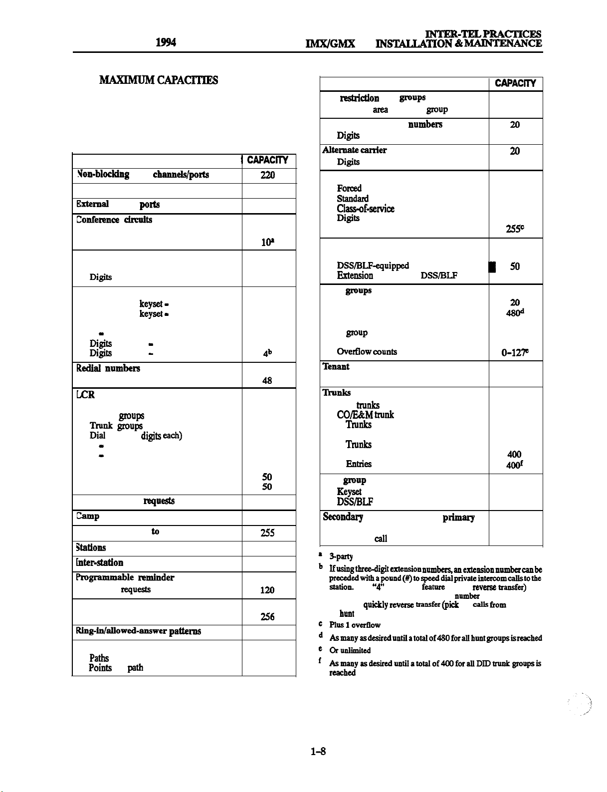
6.2
Some
of the features have maximum capacities
that are dependent on the availability of system channels and/or circuits. The features with such capacities
are listed in the following table.
FEATURE
Paging zones
available
Parties per conference
10
9
32
8
Simultaneous conferences
System speed dialing
Numbers per system
per number
Station speed dialing
Numbers per
Numbers per
Numbers per single-line set
CO and/or IC
per entry
per entry
CO
IC
CO
IC
per station
400
32
10
10
10
16
1
Digits per number
FEATURE CAPAClTY
Toll
Extended
Allowed
Account codes
SMDA account codes
Attendants
Attendant Computer Consoles
Hunt
Per system
Stations per hunt group
Announcement stations per hunt
Overflow stations
Departments per tenant group
user groups
codes par
long
distance numbem 20
per
number
numbers
per number
per code
per
groups
group
Unit
8
4
10
10
256
256
8
256
128
60
3
1
8
10
Route groups
Facility groups
rules (16
total
programmable
Facility
per facility group
group
callback requests per
system
Camp on requests per system
Callback (queue) requests per station
on by a station
Stations camped on
camped on to a tnmk group
messages per system
Message
Do-not-disturb messages
Messages par system
System forwarding paths
per
a station
per system
19
24
47
32
29
1
1
240
286
20
20
40
200
3
4
Auto
DID trunk groups
DID entries
Map
station
Secondary
be entered before a station extension
number to qaickly reverse tramfar
or hunt group.
groups
assignments
keys per station
or hunt group pilot
up) calla
184
47
184
11
184
20
8
10
16
that station
Page
Page 27
INTER-TELPRACTICES
256 INS’E4LLATION
CONTENTS
MAINTENANCE
SPECIFICATIONS
SPECIFICATIONS
Issue 1, November 1994
1. Introduction
2.
Cabling And The Main Distribution Frame (MDF)
.........................................................
........................
. Station Connections ...........................................
B.
3. Equipment Cabinet
.
B. Functional Description
Connections ............................................... 2-5
..................................................
Cabinet Description ....................................
............................................ 2-6
. Environmental Requirements ......................................
2-2
2-4
2-4
2-6
2-6
2-8
D. System Power Supply .............................................
E. Circuit Cards
....................................................
2-10
4. Station Instruments .................................................. 2-21
. IMX 256
B.
C. IMX 256 DSS/BLF Units
D. GMX-256
E. Attendant Computer Consoles
.................................................
................................................
..........................................
2-25
2-27
Units .......................................... 2-28
......................................
2-28
F. Single-Line Sets .................................................. 2-29
G. Off-Premises Extensions
H. Playback Devices .................................................
....................................
2-30
5. Additional System Equipment .........................................
.
Personal Computer (PC) For On-Site Or Stand-Alone/Remote
Programming
B. Programming PC And SMDR/SMDA Output Device Requirements
System Battery
D. Additional Information ............................................
.................................................. 2-31
...... 2-31
........................................... 2-32
2-32
Page 2-l
Page 28
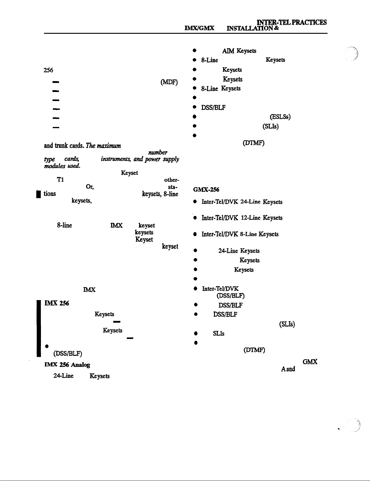
SPECIFICATIONS
Issue 1, November 1994
256
MAINTENANCE
1. INTRODUCTION
1.1
This section of the manual describes the following
System hardware:
Cabling and the Main Distribution Frame (MDF)
Equipment Cabinet
Power Supply
Circuit Cards
Station Instruments
Additional System Equipment
1.2
The 256 System has 16 slots available for station
number of
trunk9 that can be installed&pen& on the number and
of
station
used.
For example, there could be as many as
184 trunks installed (using one Keyset Card [required],
four
Cards [the maximum allowed], and 11 other-
type trunk cards). Or, there could be as many as 256 sta-
(using a combination of digital
IMX AIM keysets, and single-line sets).
NOTE: Generally, one station instrument can be in-
stalled on each available station circuit. However, the
new
“dual-circuit”
AIM
specially designed so that two of these keysets can be installed on a single circuit, if desired.
be equipped with any combination of the various keyset
models.
1.3 The trunks
and stations are controlled by the cir-
cuit cards in the equipment cabinet.
1.4
A wide variety of station instruments can be used
on the Inter-Tel IMX and GMX-256 Systems, including:
Digital Station Instruments
l
Standard Digital Keyseta (also referred to as Standard Digital Terminals)
l Executive Digital
Executive Digital Terminals)
display and non-display
(also referred to as
display only
Digital Direct Station Selection/Busy Lamp Field
units
l
Station Instruments
AIM Keysets (display only)
stations and
has been
Cards can
12-Line
Keyseta (display only)
Dual-Circuit AIM Keysets (display only)
24-Line Keysets (standard and display)
12-Line Keysets (standard and display)
Keysets (non-display only)
Attendant Computer Consoles
Enhanced Single-Line Sets (ESLSs)
Single-Line Instruments (SLIs)
Industry-Standard Single-Line, Dual-Tone
Multi-Frequency (DTMF) Sets
NOTE: With the proper software package, the Inter-Tel
GX station instruments can also be installed on the IMX
256 System. Refer to Appendix A in the back of the
manual for complete information.
Analog Station Instruments
Keysets (standard and dis-
play)
play)
(standard and dis-
play)
GMX 24-Line Keysets (standard and display)
GMX 12-Line Keysets (non-display only)
GX 24-Line Keysets (standard and display)
Attendant Computer Consoles
Field (DSWBLF) Units (single or tandem)
GMX DSWBLF Units (single only)
GX DSWBLF Units (single or tandem)
l
GMX Single-Line Instruments (SLls)
GX
Industry-Standard Single-Line, Dual-Tone
Multi-Frequency
Sets
NOTE: For more information on the GX and GMX station instruments, refer to appendixes
Bin the back
of this manual.
Page 2-2
Page 29
INTER-TELPRACTICES
256
INSTALLATION & MAINTENANCE
SPECIFICATIONS
Issue 1, November 1994
1.5 A wide variety of optional system equipment can
also be installed, including:
Off-premises extensions (OPXs) and OPXrepeaters,
refer to pages 2-30 and 3-30.
Playback devices, see pages 2-30 and 3-95.
Output device(s) for the Station Message Detail Re-
cording (SMDR), error recording, and Station Message Detail Accounting (SMDA) features, refer to
pages 2-31 and 3-98.
System battery back-up (uninterruptable power sup
ply or standby power supply), refer to page 2-32.
3-99.
Power failure transfer equipment, refer to pages
2-11 and 3-30.
Night switch equipment, refer to pages 2-11 and
3-30.
General signaling devices, refer to pages 2-11 and
3-30.
External paging speaker equipment, refer to pages
2-6 and 3-98.
Multi-port voice mail
2-32.
Facsimile machine, refer to page 2-32.
refer to page
Page 2-3
Page 30
SPECIFICATIONS
Issue 1, November
256 INSTALLATION & MAINTENANCE
2. CABLING AND
DISTRIBUTION FRAME (MDF)
2.1
ments, external equipment, and the station and trunkcir-
industry-standard, 66Ml-SO-type terminal blocks and,
if using
jack assemblies. Bridging clips are used on all terminal
blocks to complete the connections. As many as 17
blocks may be needed, including any combination of the
following:
l
blocks for CO trunk terminations and Loop/
Ground Start Card (LGC) and/or Loop Start Card
1-15 blocks for DID trunk terminations and Inward
Dialing Card (IDC) terminations.
1-15 blocks for E&M trunk terminations and E&M
Card @MC) terminations.
1-16 blocks for station cabling terminations and
Digital
RX-D), Single-Line Card (SLC), and/or Inward
Dialing Card (IDC) terminations.
1 block for optional system equipment terminations
and ROM Central Processing Unit (RCPU) Card terminations.
between the
station instru-
Cards, eight-conductor
Card (DKSC), Keyset Card (KSC or
modular
mount the terminal blocks, modular jack assemblies,
and any optional peripheral equipment.
A.
2.3
For each keyset, analog DSS/BLF Unit, Attendant
CONNECTIONS
Computer Console, single-line set, and playback
device, three-pair (24 AWG) twisted cable is run from
the station location to the MDF. All station cables are
terminated on blocks at the MDF and on six-conductor
modular jack assemblies at the station locations.
NOTE: It is recommended that three-pair twisted cable
and six-conductor modular jacks be used for all station
This
allows the various of station instruments to be easily interchanged if necessary. However, if desired,
single-line DTMF sets,
and playback devices can be installed using one-pair
twisted cable and four-conductor modular jacks.
2.4 Industry-standard, 25-pair telephone cable is used
to connect the station blocks to their corresponding station cards. Female
amphenol-type connectors on
the cables attach to the male connectors on the station
cards in the cabinet.
2.5 To meet Part 15 of FCC Regulations, all station
cables must be equipped with ferrite beads. ‘Iwo ferrite
“split” beads (two half beads) are installed on each
The beads help to reduce electromagnetic interference
2.2
The MDF requires at least a 4 x
plywood backboard. (Depending on
(1.2 x
the number of stations and trunks installed, a larger
backboard may be necessary.) This will allow room to
Each ferrite split bead, which is actually half of
a fall bead, is ordered individually (see REPLACE-
MENT PARTS for the part number). Two split beads are
required to form one complete bead.
Page 2-4
Page 31

256 INSTALLATION &
SPECIFICATIONS
Issue 1, November 1994
B.
2.6 The CO, DID, and
CONNECTIONS
trunks are terminated on
telephone company RI-type blocks, as required by FCC
regulations. Cross-connect cable is used to connect the
RI-type blocks to the CO, DID, and E&M terminal
blocks on the MDF. The trunks are then connected to the
Loop/Ground Start Cards
Inward Dialing Cards
Cards
using industry-standard, 25-pair cable.
Female 50-pin amphenol-type
Loop Start Cards
and/or E&M
on the cables
attach to the male connectors on the cards.
2.7
To meet Part 15 of FCC Regulations, all trunk
cables must be equipped with ferrite beads.
ferrite
“split” beads (two half beads) are installed on each
cable just below the amphenol-type connector.
The beads help to reduce electromagnetic interference
NOTE: Each ferrite split bead, which is actually half of
a full bead, is ordered individually (see REPLACE-
MENT PARIS for the part number). Two split beads are
required to form one complete bead.
2.8
spans are terminated on telephone company
mod-to-mod line cord is used to
directly to the
jack on the corresponding
each
span
Card.
(Or, to use the optional DB15 connector instead,
page 3-20.)
23
It is recommended that gas discharge tubes with
silicon avalanche suppressors be installed on all non-T1
trunks for lightning protection. (For
spans, the CSU
itself provides the lightning protection.) Also, in areas
with frequent occurrences of lightning, it is recommended that the cable between the telephone company
termination and the gas discharge tubes be at least 75
feet long (the cable may be coiled up if desired).
2.10 The 256 System has the following trunk characteristics:
CO to
CO to .single4ne set
Ringing voltage
Ring frequency
Loop currcnt
minimum
cross-connected to modular jack assemblies), as required by FCC regulations. Four-pair, non-reversing,
transient
Page 2-5
Page 32
SPECIFICATIONS
INSTALLATION
MAINTENANCE
3. EQUIPMENT CABINET
A.
EQUIPMENT CABINET DESCRIPTION
3.1 The 256 equipment cabinet houses the system
power supply, the Telecom Motherboard, a 17-slot card-
assembly, and the circuit cards, including: ROM
Central Processing
E&M Cards (EMCs),
Loop Start Cards (LSCs), Digital Keyset Cards
I
Line Cards (SLCs), and Inward Dialing Cards (IDCs).
3.2 Hquipment cabinet dimensions are as follows:
B.
3.3 Together, the circuit cards in the equipment cabinet perform the switching activities for the system; detect incoming calls, process data-controlled features;
control the interaction of station instruments, trunks,
and intercom calls; etc.
3.4 The system is a microprocessor-controlled, pulse
code modulation
memory (ROM) and 512k bytes random access memory
(RAM) on the ROM Central Processing Unit (RCPU)
Card. In addition, each keyset contains a microprocessor that communicates via a Keyset Card with the microprocessor on the RCPU Card.
3.5 The 256 circuitry and software combine to produce an “integrated switching matrix” of 256 time slots
(8 PCM highways Ibuses] x 32 time slots). Of the 256
time slots, 32 are reserved for conferencing and four are
reserved for
coders are installed (up to four), additional time slots are
also reserved. This leaves between 216 and 220 time
slots available for voice channels. (For a diagram of the
system voice channel allocation, refer to Figure 2-l on
page 2-7.) Therefore, the total number of
pending on the number of additional IYTMP decoders
installed on the RCPU Card).
3.6 Whenever there is a change in the system’s circuit
card
one of the PCM highways (also called buses). The indi-
vidual circuits on each card may use only those voice
channels available on the assigned PCM highway. The
Height
Width 32.0 in. (81.3 an.)
Weight
channels available ranges from 216to 22O(de-
Cards
Loaded
26.0 in. (66.0 cm.)
23.0 in. (58.4 cm.)
98 lbs. (44 kg.)
146 lbs. (66 kg.)
DESCRIPTION
time-division multiplex
decoders. If additional
all equipped cards are assigned to
Card,
Loop/Ground Start Cards
or
Cards
de-
software automatically distributes the cards to
best possible use of the available voice channels.
3.7 If there is a large mrmber of cards installed, two or
more cards may be assigned to the same PCM highway.
The voice channels on each PCM highway are then allo-
cated to the assigned cards for outside calls, intercom
calls, and pages on a first-come, first-served basis. Since
each two-way conversation requires two voice channels, the maximum number of simultaneous two-way
conversations available ranges from 108 to 110.
3.8 If, on a single
equipped than there are voice channels, there is a remote
possibility that all the voice channels could be in use at
one time (see Figure 2-l on page
a user attempting to place a call or page hears reorder
tones and must try again (the system also generates an
error message to indicate that no voice channels were
available). Generally, a voice channel will be available
on the second attempt.
NOTE: It is possible to equip more ports than there are
available voice channels, especially when installing a
number of
IMX AIM keysets installed two to a circuit. (In
fact, the programmer can equip up to 256 ports.) For total non-blocking applications, it is necessary to limit the
number of circuit cards installed in the cabinet. (Refer to
ignating certain circuit cards as non-blocking and gen-
erating voice channel allocation data for
analysis.)
3.9 As many as nine external paging ports can be used
for
Each external paging port requires au available SLC,
NOTE: When installing external paging equipment on
an LGC or LSC circuit, use a paging amplifier that pro-
vides talk battery. When installing external paging
equipment on an SLC circuit, use a paging amplifier that
DOES NOT
Usmg a pagmg amplifier
3.10 The 256 System has two music channels. If de-
sired, two different music-on-hold sources (port 1 and
port 2) maybe connected to the RCPU Card. By entering
a feature code, individual keyset users can choose to listen to background music from either of the two music
sources. Internal users will also hear music
selected source when on hold and when camped on. For
outside callers, the source for the Music-On-Hold fea-
spans, single-line sets, digital keysets, or
external paging speaker equipment.
provide talk battery.
highway, there are more ports
talk battery on an
make the
If this happens,
the
,
Page 2-6
Page 33

256
MAINTENANCE
Issue 1, November 1994
The card slot on the far right (17th slot) of the
cabinet is reserved for the RCPU Card. Other than that,
any station or trunk card may be placed in any of the remaining 16 slots.
NOTE: Information on the type of card installed in each
1
Channels Channels
2
2-l.
Channels
VOICE CHANNEL ALLOCATION
3
4
Channels
Channels
card slot must be entered through database
ruing. See page 5-170 in
3.12 The
Telecom Motherboard power cable, which
comes alreadv installed in the equipment cabinet, connects the
power supply to the Telecom Mother-
board.
5
TIME SLOTS PER HIGHWAY
1
VOICE CHANNELS
AVAILABLE
SAMPLE ALLOCATlON FOR ONE PCM HlGHWAY
NOTE: The above example shows a sample voice channel allocation for one PCM highway (voice
bus) in a heavily-loaded equipment cabinet. The system has assigned one
Card, one Single-Line
Card, and one Inward Dialing Card to the same PCh4 highway. If all three cards are designated as
“blocking” in database programming, the 48 circuits will vie for the 32 voice channels on a first-
come, first-served basis. If, however, the
rebalance the cards so that the
Card is assigned to a highway that has no more than 32 equipped
Card is designated as “non-blocking,” the system will
ports. (Refer to PRGG RAMMING, page 5-172, for information on designating certain circuit cards
as non-blocking and generating voice. channel allocation data for
analysis.)
Page 2-7
Page 34

SPECIFICATIONS
Issue 1, November
INTER-TELPRACTICES
MAINTENANCE
c.
REQUIREMENTS
3.13 The equipment cabinet and the station instruments require the following environmental conditions:
Temperature
(Cabinet) O”t0
Temperature 32” to 113’ F -40” to 185” F
(Station Instruments)
Relative Humidity 5% to 95% 5% to 95%
(Non-condensing)
up to
10,000 ft. Upto40,OOOR
(12,192 m.)
NOTE: It is recommended that the maximum operating
temperature (as stated above)
Therefore, when
the equipment cabinet and
be exceeded.
station iustruments, allow a sufficient margin for error
in case of air conditioning failure, routine mechanical
maintenance, plant shutdown, etc. As a general guideline, if the conditions are suitable for office personnel,
they are also suitable for all equipment and station instrument operation. A properly controlled environment
will help to extend the operating life of the equipment.
3.14 While in operation, a fully-loaded equipment
cabinet generates approximately 1,000 British Thermal
Units (BTUs) of heat per hour. The maximum amount of
heat generated per individual station instrument is 6.8
per hour.
NOTE: This information is provided so that any cooling
needed to meet the proper environmental conditions (as
listed in the chart) can be calculated.
D. SYSTEM POWER SUPPLY
3.15 The
system power supply is installed to provide
power to the circuit cards and to all stations. The power
supply itself is comprised of a metal chassis with various
modules installed.
3.16 The power supply must have an isolated, dedi-
cated,
57-63H2, single-phase corn-
mercial power source (for details, refer to the first
NOTE on page 3-3 in INS’WLLAIION).
3.17 All systems are equipped with one Quad Module
and one Master 30V Mod-
ule. Depending on the number and type of keysets installed, one or two Slave 30V Modules may also be
needed (see the following paragraph for details). If any
AC-ringing single-line devices are to be used, a
Generator Module must be installed. If any SLCs, IBCs,
Module must be installed.
(Refer to REPLACEMENT
and
do not use
PARIS for the part num-
bers of the various power supply modules.)
3.18 Based on the number of dual-circuit
AIM
other-type
installed, the fol-
IMX
lowing chart can be used to determine the number of
Slave 30V Modules needed. (The programming PC will
also display a message if an additional module is needed.) If it is determined that two Slave 30V Modules are
needed, a version C power supply chassis and version C
power supply modules must be used (see paragraphs
3.21
and 3.22).
(S-line
+ (digital
If y
X 0.0755) +
X 0.060)
(other analog keysets X 0.125)
8, only the Master 30V Module is re-
quired.
Ify
8, but
16, one Slave 30V Module is
also required.
Ify > 16, two Slave 30V Modules are also
required.
3.19
Located on the front side of the power supply
chassis are the ON/OPP power switch, a 1OA or 15A
fuse that isolates the AC power source from the system,
and the removable cover plate.
3.20
Located on the back side of the power supply
chassis are the AC power cable, all of the connectors for
the various power cables, and a grounding lug to connect the equipment cabinet to an earth ground.
Power Supply Modules
3.21
Currently, there are three versions of power sup
ply modules used on the 256 System: (A) part numbers
440.0102-0106, (B) part numbers 440.01% 0122, and
(C)part numbers 440.0112- 0115. (Refer to REPLACEMENT PARTS for a complete list of the part numbers.)
3.22 Version A and B
power supply modules are com-
patible with each other, and they use the same chassis.
However, due to numerous design enhancements, ver-
sion C modules and chassis are not compatible with versions A
B. Either use all version A and B power
supply modules and chassis, or use all version C modules and chassis.
Do not mix the two @pes.
Page 2-8
Page 35

3.23
The version A Ring Generator Module has a 3
MAINTENANCE
amp fuse, while all other version A power supply modules have 6 amp fuses. Maximum power outputs for
each version A module are shown below.
SPECIFICATIONS
1, November 1994
NOTE: For easier power supply module removal, each
version C power supply chassis is shipped with an extractor tool attached to the inside, front cover. The ex-
tractor tool may be used with version B and C modules
only.
6A
MASTER
90VAC
3.24
Except for the Quad Module
Frequency, mI-k
fuse,
output of 23A, and +12VDC output of 4A), version B
and C power supply modules have the same fuses and
maximum power outputs. Also, there is only one version
C 3OV Module, which can be used as either a master or a
slave.
Voltage
3.25 To reduce the effects of
and Spike Protection
AC voltage surges
and
spikes that may cause system malfunctions, false logic,
and/or damage to the electronic components, a surge/
spike protector is provided. (Refer to REPLACEMENT
PARTS for the part number.) Its specifications are:
Clamp voltage transients at 300VDC within 5 nanoseconds when exposed to waveforms as described in
the ANSI/IEEE Standard C62.41-1980 (IEEE 587).
l
Reduces RFI/EMI noise by at least 20dB at frequencies between &I-Ix and 3OMHz.
Battery Back-Up
3.26 To provide back-up power in the event of a power
failure or brownout condition, the power supply can
have optional battery back-up using a customer-provided
power supply (UPS) unit or a
standby power supply (SPS) unit. Refer to page 2-32 for
more information.
Page 2-9
Page 36
1,
November 1994
256 INSTALLATION
MAINTENANCE
E. CIRCUITCARDS
3.27 In addition to the power supply, the equipment
cabinet houses the Telecom Motherboard and the circuit
cards that control and coordinate the functions of the
system. Up to 17 cards may be connected to the Telecom
Motherboard, including:
1
ROM central promsing unit
Inward Dialing Card @DC)
l-15’
l-15
l-4
l
Card
Start Card (LGC)
rquircd
Descriptions of the cards are given in the follow-
ing paragraphs. Drawings of the cards are located in the
section.
ROM Central Processing Unit
3.29
The RCPU Card contains the main controlling
Card
r and associated control logic and
memory circuits. It is under the control of a program,
stored in the ROM, which is activated when the system
is powered up. ROMs containing the system software
are installed on the RCPU Card before it is installed in
the equipment cabinet.
330
resources:
RS-232-C (DB9)
connectors (g-pin subminia-
ture “D” male connectors) for connecting SMDR/
output devices and/or a personal computer
for programming the system database (see page
2-31 for requirements).
Voltage test points
for checking the system
and AC ring voltage levels. To measure system voltage levels, voltmeter probes are
into the
ground test point and the desired voltage test point.
Refer to
page 3-45, for details.
Reset
is used to manually reset the system
during troubleshooting. This is a software reset
nor reset), not a hardware reset (major reset). Pushing this switch does the following:
Preserves the battery-backed database iuforma-
tion, non-conference calls in progress, outside
calls being dialed from keyset stations, inter-station messages, calls on individual hold, do-not-
disturb messages, and reminder messages. A call
on system hold is changed to individual hold at
the station that placed it on hold.
Restores
decoders, modem access, and
speech channels, and resets the station clocks to
match the system clock. Updates trunk key, DSS/
key,
key, and feature key lamp
Interrupts system operation, which disconnects
pages in progress, calls ringing in, calls using the
conference resources (as described on the next
page), and calls using DTMF decoders. Camped-
on calls are disconnected and queue requests are
canceled.
Terminates system and user programming.
Database back-up battery
lithium
battery) that can support the database for at least two
months of accumulated system down time.
Battery voltage test points and check button for
checking the database back-up battery charge. If the
battery voltage is not greater than 2.!WDC, replace
the battery.
back-up jumper strap for activating the
database back-up battery. The jumper strap should
be placed in the ON position (over the top two pins)
before the RCPU Card is installed. When the card is
taken out of service for repair or storage, the jumper
strap should be placed in the OFF position (lower
two pins) to preserve the battery charge.
NOTE: Placing the
jumper strap
the
OFF position erases the database.
Male
necting up to two music sources, a power failure
connector for con-
transfer relay, and a general purpose relay:
LED
show main processor operation
(CPU ACTIVE), major system alarms (MAJOR
ALARM), minor system alarms
ALARM), database error occurrences
ERROR), database back-up battery connection
(POWER ALARM), and external clock activity
(EXTERNAL CLOCK ACTIVE). Refer to TROUBLESHOOTING for detailed LED information.
Page 2-10
Up to two external music sources (such as radios,
tape players, etc.) may be connected to the
RCPU Card. AGC circuits on the RCPU Card au-
tomatically hold the volume of each music
source to a predetermined level that is slightly
lower than the normal voice volume, as required
by FCC regulations. Optimal input level is
page 3-99.
Page 37
INTER-TELlPRACTICES
256 INSTALLATION
MAINTENANCE
SPECIFICATIONS
Issue 1, November
Relay 1, which is the power failure transfer relay
(and cannot be changed),can be used to connect
one or more single-line sets to predetermined CO
trunks in the event of processor card failure or a
power failure. (If ground start trunks are used,
the single-line set must be equipped with a
ground start button.) The output is a normally-
open DPDT relay that is held closed during system operation. Additional equipment needed
includes a customer-provided PFT relay card
and card mounting case. The RCPU Card relay
contact ratings are listed below. (See also page
at 125VAC
Relay 2 can be used to activate an external sig-
naling device when a call rings in on assigned
CO trunks. The dry contacts follow the normal
conds off). Ring in for the relay can be programmed for day and/or night modes.
Or, relay 2 can be used for night switch to turn on
or off lights, an alarm system, or other devices.
The relay, which is activated when an attendant
in the designated tenant group places the system
night mode, causes the swing connection to
move from the “break” to the “make” position.
Or, relay 2 can be used for activating external
paging. The relay, which is activated when the
paging zone to which it is assigned is accessed by
a station user, causes the swing connection to
move from the “break” to the “make” position.
This contact can be used to activate the microphone input of an externally-mounted paging
amplifier.
Music-on-hold (MOJX) jumper
straps for enabling
one or both of the external music sources that are
heard by callers when they are placed on hold or
camped on. If connecting an external music source,
place the associated jumper strap in the ON position
(over the top two pins). Then, in the database, each
trunk group can be assigned music port 1, music port
2, silence, or tick-tones. Refer to PROGRAM-
MING, page
and
modem interface for re-
mote progr
fault
the
Bell modem is
assigned extension number 270, the 12OO-baud Bell
modem is 271, the 300-baud CCITT modem is 272,
and the 1200-lbaud CCI’IT modem is 273. Any attendant can transfer a call to the modem, or it can be
accessed directly using DISA.
for connecting up to 32
parties in multiple conferences. There can be up to
10 simultaneous three-way conferences or four si-
multaneous eight-party conferences. Except for the
fact that there can be only eight parties involved in a
single conference, any combination using the 32
dedicated conference circuits is possible. The con-
ferencing resources also support the Call Forward,
Call Transfer, Station Call Monitoring, and DISA
features when two trunks are connected. Conferenc-
ing utilizes a zero
loss function so that there is no
substantial loss in voice volume no matter howmany
people are in the conference.
DTMF decoding circuits
(four) are used when single-line sets are dialing and when features such as
DISA and Automated Attendant are used. They are
also used for the Unsupervised CO Call Continuation feature (as described in paragraph 4.88 on page
4-37).
These four decoders convert DTMF signals
to the digital codes used by the system. They are in
use only while the dialed number is beii processed,
not for the duration of the call. If all four DTMF decoders are busy, the user may camp on.
NOTE: If necessary, up to four additional DTMF
decoding circuits can be added to the RCPU Card by
installing
Expansion Chips (two chips per
circuit; four chips per kit). Refer REPLACEMENT
PARIS for the part number.
Tone generating circuit generates DTMF tones
whenever needed by the system (for example, when
a station user uses one of the system auto-dial features, such as LCR, Call Forward To The public Network, Station or System Speed Dialing, etc.). The
circuit is also used to produce all of the system tones
(busy, reorder, do-not-disturb, etc.) heard by digital
dant users. (Analog keysets generate their own sys-
I
tern tones.)
A-law/mu-law jumper strap for choosing the
method of encoding sampled audio waveforms used
in pulse code modulation systems. Domestic telephone companies use the mu-law method. The a-law
method is widely used outside of North America.
Page 2-11
Page 38
SPECIFICATIONS
Issue 1, November 1994
MAINTENANCE
Cards
Single-Line Cards
331
Station instrnments are connected to the station
or KSC-Ds) and
cards in the equipment cabinet. Digital keysets are con-
nected to Digital Keyset Cards. Analog keysets, analog
I
connected to
Single-Line Instruments
Cards. Enhanced Single-Line Sets
standard single-line DTMF sets, and playback devices
are
to either Single-Line Cards (AC-ringing
instruments only) or Inward Dialing Cards (AC or DC).
For more
on Inward Dialing Cards, refer to
page 2-15.
332
Digital
Card (DKSC):
Each DKSC provides up to 16 circuits for connecting digital
Each circuit has a self-correcting thermistor to protect
the system from damage due to a short circuit in the station cabling. If a short circuit causes a thermistor to
open, it will automatically close when the short is removed.
3.33 Up to 50 digital keysets may be equipped with up
to four digital DSS/BLF Units each. The units are connected in series to the PC Data Port Module (PCDPM)
on the back of the corresponding keyset. Unlike analog
units, digital DSWBLF Units do nor require station cabling separate from the keyset’s cabling; instead, they are
powered by their own AC transformer.
334
Each DKSC has a green LED (CARD ON-LINE)
to indicate the card’s functional readiness and 16 green
BUSY) to indicate whether any circuit
on the card is busy (see Figure 3-30 on page 3-48).
3.35
Each
comes equipped with one Digital
Signal Processor (DSP) that provides resources for up to
12 shared speakerphones. If desired, a second DSP can
he installed to provide an additional 12 shared speakerphone resources.
NOTE: For information on using shared speakerphones
for digital
3.36
see page 4-40 in
Card
or KSC-D): Each KSC (or
KSC-D, see the following note) provides up to eight cir-
cuits for connecting analog
analog
Units, and Attendant Computer Consoles to the system.
Up to 50 KSC circuits can be used for installing analog
connected to a single card. Some
have a
from damage due to a short circuit in the station cabling.
Newer version KSCs have eight self-correcting thermistors (one for each circuit) instead of the fuse. If a short
circuit causes a thermistor to open, it will automatically
close when the short is removed.
NOTE: To install any
the new “dual-circuit” version
IMX AIM keyseta nuo to
Card
(KSC-D) must be used (see REPLACEMENT PARTS
for the part number). To install
to a
337
either the KSC or the KSC-D can be used.
Each KSC has an LED (CARD ACTIVE) to indi-
AIM keysets one
cate the card’s functional readiness. In addition,
dividual circuit on each card has an LED to indicate the
circuit’s activity (lit green) or failure (lit red).
Single-Line Card (SLC):
are used for
connecting AC-ringing ESLSs, SLIs, single-line DTMF
sets, and playback devices. They can also be used for
connecting external paging equipment. Off-premises
stations cannot be legally connected to SLCs; instead,
Inward Dialing Cards (IDCa) must be used (see page
out-
put. Thisfuse
cannot be
in
If the fuse
is defective, the entire card must be sent in for repair.
Newer version SLCs have a self-correcting thermistor
instead of the fuse. If a short circuit causea a thermistor
to open, it will automatically close when the short is removed.
NOTE: For optimal performance, it is recommended
that voice mail units and automated attendant playback
devices be installed on IDC circuits rather than SLC circuits. Doing this mutes any DTMF digits automatically
dialed by the system (e.g., those generated when tran-
sferriug or forwarding an outside caller to voice mail).
339
Each SLC has an LED
ACTIVE) to indicate the card’s functional readiness. In addition, each individual circuit on each card has an LED to indicate the
circuit’s activity (lit green) or failure (lit red).
3.40
Station configuration: Station instrument con-
figuration depends on the number and type of station
cards installed in the equipment cabinet. There can be
any combination of station cards allowing combinations
of keysets in eight-station increments (or 16-station increments if using digital
AIM
and single-line sets or playback
or
dual-circuit
devices in increments of 16 (using SLCs) or in increments of eight (using IDCs).
NOTE: At least one
KSC-D)
be installed to provide an attendant
Card
KSC, or
(equipped with a display keyset or an Attendant Computer Console) that can receive system alarm messages,
program system data, act as the attendant for unsupervised CO recalls, etc.
3.41
Each station card circuit is assigned a hardware
address number according to the card’s slot in the equip
Page 2-12
Page 39

256 IN-TION
MAINTENANCE
Issue 1. November 1994
ment cabinet and the location of the circuit on the card.
For example, circuit 1.2 is the second circuit on the first
card installed in the equipment cabinet.
NOTE: In the default database configuration, there are
no keyset circuits assigned for
3.42 When the system is first powered up, the default
configuration is used to assign extension numbers to the
station circuits. On IMX 256 Systems, card slots l-4 are
considered KSCs or KSC-Ds, slots 5-6 are DKSC!s, slots
7-g are unassigned, slots 9-12 are
I
13-16 are LGCs. On GMX-256 Systems, card slots
are considered KSCs or KSC-Ds, slots 9-12 are SLCs,
and slots 13-16 are LGCs. Changes to the default con-
figuration can be made through database programming.
installed two to a circuit (e.g.,
dual-circuit JMX
and
and slots
Refer to PRGGRAMMIN G, page 5-170, for more in-
formation.
3.43 The system assigns extension number 100 to station circuit 1.1, extension number 101 to station circuit
1.2, and so on to match the initial configuration. Circuit
1.1 is equipped as the primary attendant’s keyset when
the system is in the default configuration. If desired, the
circuits can be assigned different extension numbers
and/or four-digit extension numbers through database
programming. Refer to
for more information.
NOTE: When
dual circuits, the “B” circuits do not have extension
numbers until they are assigned in database program-
ming-
IMX AIM keysets are assigned to
G, page 5-58,
Page 2-13
Page 40

SPECIFICATIONS
Issue 1, November 1994
INSTALLATION
MAINTENANCE
Start Cards
3.44 Each LGC and
has circuitry for up to eight
and Loop Start
trunks. LGC and LSC circuits may also be used for installing external paging equipment. LSCs can only have
loop start trunks connected to them. LGCs can have either loop start or ground start trunks. Each individual
circuit on the LGC has two
straps for designating
whether the circuit is loop start or ground start. Individual trunks may be designated as either loop start or
ground start in database programming.
NOTE: For each LGC circuit, both jumper straps must
be in the proper (LS or GS) position. If the strap settings
are mixed, or if one or both of the straps is missing, the
circuit will not function properly. Also, when setting the
straps, note the unique ordering of the LGC circuits as
shown in Figure 3-34 on page 3-55.
3.45
For optimal CO trunk transmission performance,
each LGC and LSC circuit should be “hybrid balanced”
in database programming. Hybrid balancing refers to
selecting the balance network
loaded
-that best matches the trunk’s impedance. Re-
fer to PROGRAh4MlN
G, page 5-147, for details.
ideal, loaded, or un-
3.46 Should voice transmit or voice receive volume
problems occur, the receive gain
the transmit
gain for individual trunks can be adjusted in database
programming. Refer to PROGRAMMIN
G, page 5-103,
for additional information.
3.47 Each
and LSC has 16 speciallydesigned
fuses soldered to the card to protect it from large voltage
surges due to lightning. If a fuse is open (blown), it may
mean that other parts of the card have also been dam-
aged. For this reason, open fuses must not be replaced in
the field. Instead, the entire card must be returned for
testing and possible repair. Failure to follow this policy
will void the warranty on the card.
3.48 When the system is in the default configuration,
all trunks are configured for M’MF signaling. If necessary, some or all of the trunks can be reprogrammed for
dial-pulse signaling through database programming.
Although both the LGC and the LSC can use dial-pulse
trunks, the pulse circuitry on the LGC is more sophisti-
cated and may provide better performance in
uations.
Single-line sets generate their own
tones
when dialing. If used on dial-pulse trunks, both the
signals generated by the system are sent to the central
office, which may be a problem if the central office rec-
both. To avoid this problem, single-line sets
should be restricted to LCR only when using dial-pulse
trunks. Then, only the LCR-generated dial-pulse signals
will be sent to the central office.
3.49 With loop start trunks, it is sometimes possible
for the user to attempt to place an outgoing call and
instead be connected to an incoming call on the same
trunk. This unintended connection, called glare, is due
to the natural switching delay characteristics of the telco
equipment and the system. Previously, if the user did not
dial a valid outside number, the glare connection was
dropped. The software now allows the incoming call to
remain connected, while still protecting against possible toll fraud. A new system-wide programmable op
tion, called Drop Incomplete Outgoing Calls, has been
added to the Miscellaneous System-Wide information
screen, as shown on page 5-67 in PROGlWMMING.
3.50 The CO circuits are assigned hardware address
numbers according to the card’s slot in the equipment
cabinet and the location of the circuit on the card. For
example, when using the initial configuration (see para-
graph 3.42), CO circuit 13.4 is the fourth circuit on the
13th card (an LGC) installed.
351
When the system is in the default
the first four trunk keys on each keyset are assigned as
call keys for incoming call indication/access.
AN-
SWER key may also be used to access incoming calls.)
No individual trunk keys or trunk group keys are assigned. Key assignments can be designated in database
programming. Refer to PROG
RAMMING, page 5-44,
for more information.
3.52 CO trunk groups may be assigned on a tenant-by-
tenant basis. Up to 47 CO trunk groups can be distributed among the tenant
Refer to
Page 2-14
Page 41

256
SPECIFICATIONS
Issue 1, November 1994
Inward Dialing Cards
353
ing (DID) trunks and off-premises single-line stations.
Like SLCs (described on page 2-12), IDCs may also be
used for connecting on-premises single-line sets and
playback devices. In fact, for optimal performance, it is
recommended that voice mail units and automated attendant playback devices be installed on IDC circuits
rather than SLC circuits. Doing this mutes any DTMF
digits automatically dialed by the system (e.g., those
generated when transferring or forwarding an outside
caller to voice mail).
NOTE: IDCs do not support message waiting applications. If single-line sets with message waiting lamps are
installed on IDCs, the lamps will not function.
3.54 On older-version IDCs, each IDC circuit has a
2-pin AC ENABLE jumper strap that must be removed
when installing a DID trunk or a DC-ringing station.
AC-ringing off-premises stations can be connected directly to IDC circuits provided that both the optional
Module and the optional Ring Generator Module
are installed in the power supply chassis
HVRA Units, power supplies, and ring generators are
not needed).
3.55 On newer-version IDCs, each IDC circuit has a
3-pin RING SELECT jumper strap that must be set in
either the AC/OPX position (over the bottom two pins)
or the DC/DID position (over the top two pins).
I
NOTE: When setting the jumper straps on either ver-
sion card, note the unique ordering of the IDC circuits as
shown in Figure 3-33 on page 3-53.
3.56 Each IDC can have up to eight DID trunks or up
to eight single-line sets, or any combination of the two.
357
DID trunks may be programmed to ring in to in-
dividual stations, multiple stations, or hunt groups. Or,
they may be programmed
to
ring in as
Ifpro-
grammed to ring in at a single station, the DID call will
follow any programmed forward.
3.58 DID trunk groups may be assigned on a tenant-
by-tenant basis. Up to 11 DID trunk groups can be distributed among the tenant groups. Refer to
page 4-15, for more information. Also, DID trunk
groups maybe designated as immediate start, wink start,
or delay start in database programming.
3.59 Each IDC has 16 specially-designed fuses sol-
dered to the card to protect it from large voltage surges
due to lightning. If a fuse is open (blown), it may mean
that other parts of the card have also been damaged. For
this reason, open fuses must not be replaced in the field.
Instead, the entire card must be returned for testing and
possible repair. Failure to follow this policy will void the
warranty on the card.
Page 2-15
Page 42
Issue 1, November 1994
256
MAINTENANCE
E&M Cards
3.60
E&M trunks, also called “tie” lines, are special
trunks that tie individual telephone systems together.
They allow the users of either telephone system transparent access to the users and resources of the other telephone system, often for less than what it would cost to
use normal long distance service.
3.61 E&M (literally “ear” and “mouth”) refers to the
pair of wires that carry the signals between the trunk
equipment and a separate signaling unit. The M lead
transmits a ground or battery condition to the signaling
equipment, while the E lead receives open or ground signals from the signaling equipment.
3.62
If designated for “auto ring-in,” E&M trunks
may
programmed to ring in to individual stations,
multiple stations, or hunt groups on the other telephone
system. (If programmed to ring in at a single station, the
E&M call will follow any programmed forward.)
3.63 If designated for “dial repeating,” E&M trunks
may be programmed to ring in as DISA calls.
3.64 Additionally, LCR may be used to turn what
would normally be a long distance call into a local call.
For example, when a call is made from one telephone
system to a long distance number that is local to the other telephone system, LCR could be programmed to
route the call through the E&M network to make a local
call from the other telephone system.
cannot be hybrid balanced). Hybrid balancing refers to
selecting the balance network
ideal, loaded, or unloaded -that best matches the trunk’s impedance. Refer to PRGGRAh4MlN G, page 5-147, for details.
3.68 Should voice transmit or voice receive volume
problems occur, the receive gain and/or the transmit
gain for individual E&M trunks can be adjusted in database programming. Refer to PROGRAMMING, page
S-103, for additional information.
3.69 Each EMC has 24 speciallydesigned fuses soldered to the card to protect it from large voltage surges
due to lightning. If a fuse is open (blown), it may mean
that other parts of the card have also been damaged. For
this reason, open fuses must not be replaced in the field.
Instead, the entire card must be returned for testing and
possible repair. Failure to follow this policy will void the
warranty on the card.
3.70 When the system is in the default configuration,
all E&M trunks are configured for IYI’MF signaling and
dial repeating. If necessary, some or all of the trunks can
be reprogrammed for dial-pulse signaling and/or auto
ring-in through database programming.
3.71 The
E&M circuits are assigned hardware address
numbers according to the card’s slot in the equipment
cabinet and the location of the circuit on the card. For
example,
circuit 13.4 refers to the fourth circuit on
the 13th card (an EMC) installed in the equipment cabinet.
3.65
Each EMC has circuitry for up to four E&M
trunks. Each individual circuit on the EMC has two
jumper straps, one for selecting the signaling type
4, or 5) and one for selecting the audio type (2-wire or
The signaling and audio type for each circuit
must also be programmed in the database.
3.66 Although not currently operational, the EMC is
equipped with a “make-busy” switch for removing all
circuits on the card from service and placing them back
in again, The switch is reserved for possible future use.
3.67
For optimal E&M trunk transmission performance, each 2-wire EMC circuit should be “hybrid balanced” in database programming
circuits
3.72 When the system is in the default con.&uration,
the
four trunk keys on each keyset are assigned as
call keys for incoming call indication/access. (The ANSWER key may also be used to access incoming calls.)
No individual E&M trunk keys or trunk group keys are
assigned. Key assignments can be designated in database programming. Refer to PROGRAMMING, page
for more information.
3.73
trunk groups may be assigned on a tenant-
by-tenant basis. Up to 47 E&M trunk groups can be distributed among the tenant groups. Refer to
page 4-15, for more information. Also, E&M trunk
groups may be designated as immediate start, wink start,
or delay start in database programming.
Page 2-16
Page 43

NOTE: The acronym for the
not be confused with the special
Card
-should
digital carrier sys-
tem (which operates at twice the data rate of the standard
carrier system). The 256
Card does not support
3.74 The term “Tl” refers to a specific digital method
of transmitting voice and data; it is the basic 24-chamtel
time-division multiplex (TDM), 1.544 Mb/s pulse code
modulation (PCM) system as used in the United States.
3.75 The
standard, which was developed as a
method of reducing cabling and increasing transmission
quality between distant central offices, is actually a subset of a multi-level Digital Signal (DS) scheme. Inpopu-
lar usage,
refers to the
rate as transmitted via any
type of media (e.g., copper wire, fiber optics, or microwave).
3.76 Since each
span actually consists of 24 individual circuits (or channels) multiplexed together, it is
often less expensive to purchase a single
span than it
is to purchase multiple individual trunks. Each of the 24
circuits can be programmed as a loop start, ground
start, DID, E&M, or OPXtrunk (or as unequipped). Any
combination is possible.
3.77 “Fractional”
often called
is a special
service where only a portion of the 24 channels are used
and paid for. To implement fractional
(if available),
equip only those circuits that are provided.
NOTE: Currently, the
Card is used to transmit voice
signals only, not data. In the future, data transmissions
over
circuits may also be supported.
3.78 To interface with the public network, each
Card must be equipped with a customer-provided, on-
board Channel Service Unit (CSU) or a customer-provided, external CSU. If the optional on-board CSU is
installed, the programmer must select the line build-out
attenuation, which is determined by the distance
to the nearest public network
mation is available from the
repeater. (This infor-
provider.) If an external
CSU is installed instead, the programmer must select
the DSX-1 line length, which is determined by the distance from the
Card to the external CSU. (The card
and the external CSU must be located in the same building, and the cabling between them must be less than 655
feet.)
The on-board CSU can now be purchased
directly from Inter-Tel using part number 440.3004.
3.79
Although most
public network, it is possible to use
interfaces will be with the
Cards to connect
two telephone systems together (e.g., two 256 Systems).
SPECIFICATIONS
Issue 1. November 1994
To do this without CSUs, the two systems must be lo-
cated in the same building and the cabling between them
must be less than 655 feet. If each system is equipped
with a CSU, they may be located in separate buildings
and the cabling between them may be as long as 6000
feet. (See page 3-34 for more information on connect-
ing two 256
Cards together.)
NOTE: For information on programming various types
of
installations, refer to pages 5-122 to 5-129.
In the future, a
span could possibly be used to
connect the 256 System to a host computer via a digital
multiplexed interface
Also, the
Card has
been designed to interface with the coming Integrated
Services Digital Network (ISDN) features, when available.
3.81 When a
span is used to connect a 256 System
to the public network or to another telephone system, it
is important that the two endpoints communicate at the
same frequency. Since it is practically impossible for
both endpoints to have clocks running at identical
and the other endpoint is given “slave” clock status. The
slave clock can then extract and lock onto the master
clock frequency from the incoming
information.
This master/slave synchronixation is programmed in the
256 System is automatically designated as the slave
clock.
3.82 When information (currently, voice only) is
transmitted over a
span, a “framing” bit is added so
that the receiving end can recognize where the information begins and ends (as long as the clock circuitry of the
two endpoints is synchronized). Currently, the 256 Sys-
tem supports the two major types of framing schemes in
use today: D4 Super&me, which is the most common,
and Extended Superframe @SF), which is required to
support future ISDN and DMI features. For
trans-
missions, D4 Superframe is quite adequate. However,
for data transmissions (not currently supported), ESF is
much more reliable and efficient.
383 Digital information is transmitted over the
span as a series of
and
(e.g., .
000 0000
If there are too many consecutive zeroes, the
clock extraction circuitry will not operate correctly.
To prevent this,
carrier equipment limits the number
of consecutive zeroes. The 256 System supports the two
major types of xero code suppression schemes in use
today: Alternate Mark Inversion
also called
bit-7 stuffing, and Bipolar Eight Zero Substitution
Again, for voice transmissions,
is quite
adequate. However, for 64 kb/s clear channel data transmissions (not currently supported), BSES is required.
Page 2-17
Page 44

SPECIFICATIONS
Issue 1, November
&
3.84 Like the
repeater distance, the framing
scheme type and xero code suppression scheme type are
also available from the
ing a
span, always request the following information
provider. In fact, when order-
from the Tl provider:
Framing scheme: D4
code suppression scheme:
If
the
optional
repeater (for determining the line build-out
attenuation): O-1599 feet
on-board CSU is to be inshlle~
the
to
or ESF
or
public
1600-2999 feet
feet (OdB)
3.85
Each
has circuitry for up to 24 trunk chan-
nels. The 24 channels (or circuits) can be any combina-
E&M trunks, or OPX trunks.
3.86 The
Card itself is equipped with the following
resources:
l
LED indicators are
each circuit and to show
provided to show the status of
trunk alarms and board-
level error occurrences. Refer to the
SHOOTING section of this manual for additional
LED information.
Audio jack (8-pin, a-conductor modular jack) for
possible future use.
NOTE: The audio jack is currently used for engi-
neering diagnostic purposes only.
Alarm relay jack
jack) for connecting optional
vices. The
l Serial port jack
Card relay contact ratings are:
CONTA~
at
at
at 30VDC
modular
alarm signaling de-
&conductor
modular jack) for possible future use.
NOTE: The serial port jack is currently used for engineering diagnostic purposes only.
l Tl span jack
jack)
for connecting a single, 24-channel
the
Card. (If this jack is used, do not use the op-
modular
span to
tional DB15 connector also provided on the card.)
NOTE: All
spans should be disconnected from
their cards before turning the system power on or off.
l Dual bantam jack(with transmit and receive audio
ports) for connecting
test equipment to the
Card and monitoring the transmit and receive signals.
CAUTION
When a live
span is installed on the
Card, test
equipment should be used for monitoring purposes
only. Do not attempt to send signals over either the
transmit or receive audio ports on the
Card if a
span is installed. Also, be sure the test equipment is
set in the “bridge” mode.
Optional Tl span DB15 connector
sub
miniature “D” female connector) for connecting a
single, 24-channel
span to the
Card.
NOTE: In certain situations (e.g., when using an external CSU equipped with a DB15 connector), it
may be more convenient to use the optional DB15
connector instead of the standard RJ48C jack also
provided on the card.
Make-busy switch with LED for removing all cir-
cuits on the card from service and placing them back
in again. Pressing the switch will light the LED and
begin the process of “busying out” each circuit not in
use. The circuits that are in use are then busied out as
soon as the users hang up. When all circuits are
busied out, the make-busy LED and all 24 circuit
flash slowly, and the card can be removed
from its slot in the cabinet.
card is not removed
within a certain amount of time, a programmable
timer expires and the card returns to normal operation; however, the make-busy LED will then flash
rapidly until the make-busy switch is released.
Channel Service Unit
connector for install-
ing the optional on-board CSU Module. If the
Card interfaces with the public network, either the
on-board CSU Module or an external CSU must be
connected to the card.
plug
for indicating whether the
on-board CSU is installed. If the on-board CSU is installed, place the jumper plug in the CSU position. If
there is no on-board CSU, place the jumper plug in
the DSX position. This information must also be
programmed in the database.
l
Line build-out jumper plug
line build-out (LBO) attenuation of the
for selecting the proper
span connected to the card. This selection is necessary only if
the optional on-board CSU is installed. If the dis-
tance between the equipment cabinet and the closet
public network
repeater is less than 1600 feet,
place the jumper plug in the 15dB position. If the distance is between 1600 and 2999 feet, place the jump
er plug in the 7.5dB position. And, if the distance is
Page 2-18
Page 45
INSTALLATION
MAINTENANCE
SPECIFICATIONS
Issue 1, November 1994
between 3ooO
and 6000 feet, place the jumper plug
in the OdB position. This information, which can be
obtained from the
provider, must also
pro-
grammed in the database.
Compared to the other trunk cards in the system,
the
Card is very sophisticated and offers some unique
programming options. The information that is pro-
grammed comnwn to all Tl
installed in the sys-
tem includes:
feedbackconfiguration: When a number is
dialed over a
circuit, the user hears the feedback
from the signals (either M’MF or dial-pulse, depending on how the circuit is designated). By adjusting the
gain control or the dial-pulse gain
control (from -15dB to 15dB), the programmer can
determine how loud the signals appear to the user. If
the circuit is designated for dial-pulse signaling, the
programmer can also select the type of dial-pulse
tone the user hears (23 different tones are available).
Error thresholds: The
cal thresholds (number per hour and
day) for certain
programmer can set muneri-
per
Card errors. If a threshold is ex-
ceeded, an error is printed on the SMDR report.
Reference clock back-up priorities: One
of the
Cards installed in the system must be programmed
as the system reference clock (see “reference clock
programming” following paragraph 3.88).
than one
Card is installed in the system, the pro-
more
grammer may designate one or more of the cards as a
“backup” to the system reference clock. Then, if the
Card acting as the system reference clock fails or
is taken out of service, the next
Card on the back-
up priority list takes over.
3.88 The
each
Card type:
information that is programmed
installed in the system includes:
The programmer must select the type of
to
framing scheme, D4 Superframe or Extended Super-
frame (ESF), used by the
span connected to each
card.
Zero code suppression scheme: The programmer
must select the type zero suppression scheme,
(bit-7
or Bipolar Eight Zero Substitution
span comected to each card.
PCM encoding law: In pulse code modulation
encoding analog signals (sampled audio wave-
forms) into digital signals. In North America and Japan, the “mu-law” method is normally used. In other
places, like Europe, the “a-law” method is widely
used. The programmer must select both the transmit
and receive method of encoding used by the
Card.
mu-law to mu-law.
Relay activation: If desired, the programmer may
enable the two relays,
line error and
line OK,
on the Tl Card.
Channel
unit
The programmer
must designate whether the optional on-board CSU
is installed on the
Card.
database selection
must match the jumper selection on the card.)
Line build-out
If the optional on-board
CSU is installed, the programmer must designate the
attenuation of the
connected to the
card. This value is determined by the distance to the
nearest public network
repeater. (The database
selection must match the jumper selection on the
card.)
DSX-1
installed, the programmer must designate the
length of the cabling between the
external CSU, or between the
length: If the optional on-board CSU is
Card and the
Card and the other
telephone system to which it is connected.
Reference clock programming:
must first designate whether the
programmer
Card is con-
nected to the public network. If it is, the card is auto-
matically designated as a slave clock (the public
network always acts as the master clock). If the card
is not connected to the public network, but is instead
connected to another
Card or a card in another
telephone system, the programmer must designate
whether the card is a master clock or a slave clock (in
relation to the card on the other end).
In addition, one of the
Cards installed in the system must be programmed as the system reference
clock. The reference clock then becomes the clock
for all the other cards in the system. If there is no
Card acting as the reference clock, the Matrix Card
becomes the system reference clock.
If a
Card is designated as both a master clock and
the system reference clock, the programmer must
then designate whether the card’s on-board oscillator is the source of the clock or whether there is an
external clock.
NOTE: The external clock option is provided for
possible future use only. For now, always designate
the card’s on-board oscillator as the source of the
clock.
Test tone:
digital test tone (1007Ex, OdBM, sine wave) over the
selected
circuit. The tone can be verified by mon-
itoring the transmit audio port on the card’s dual bantam jack.
Page 2-19
Page 46
SPECIFICATIONS
Issue 1, November 1994
256 INSTALLATION
MAINTENANCE
Error diagnostics: If
generate the current
desired; the programmer can
error counts (by hour and by
day) for the selected card. The error counts can be
displayed in a graphical or tabular format, printed
(stand-alone/remote only), or saved in a file for future reference.
3.89 The information that is programmed
each
(i.e., each of the 24 channels) on the
Card includes:
Circuit type: Each individual circuit can be pro-
grammed
Diital gain
a loop start, ground start, DID,
As with the other trunk cards,
E&M,
or
should voice transmit or voice receive volume
occur, the programmer can adjust the receive
gain and/or the transmit gain (-15dB to 15dB) for individual
DTMF’ or dial-pulse
circuits.
When the system is
in the default configuration, all trunk circuits are
configured for DTMP signaling. If necessary, some
or all of the circuits can be reprogrammed for
pulse signaling.
circuits are assigned hardware address
numbers according to the card’s slot in the equipment
cabinet and the location of the circuit on the card. For
example,
card, a
3.91
circuit 6.21 is the 21st circuit on the 6th
installed in the equipment cabinet.
Special
requirements: It is recom-
mended that special high-speed data cable with the following characteristics be used for all
installations:
22 AWG
Individually shielded two-pair (or with the transmit
and receive pairs run in separate cables or binder
ABAM or PIC (a level-3 cable designed specifically
for the T-carrier transmission rate)
Maximum capacitance of lSpF/ft.
Maximum attenuation of
ft. at
and 70“ F
NOTE: The programming prompts for
tion and DSX-1 line length assume that proper
(with the above characteristics) is
attenua-
cable
used. When
transmitting over shorter distances (e.g., when the nearest public network
repeater is less than 2000 feet
from the MDF), it may be possible to use standard two-
pair voice frequency cable instead; however, the programmer may have to compensate by selecting longer
distances or DSX-1 line lengths. Also,
no
matter
which type of cable is used, the transmit and receive
pairs must be shielded from each other (or
in sepa-
rate cables or binder groups).
3.92 If the optional DB15
on the
Card is
used in place of the standard RJ48C jack, a flat, 2SAWG,
twisted-pair ribbon cable with a maximum capacitance
of 16pF/ft. may be used for distances of up to 50 feet (see
page 3-20 for more information). For distances longer
than 50 feet, use the special high-speed data cable
described in paragraph 3.91.
Page 2-20
Page 47
STALLATION
MAINTENANCE
SPECIFICATIONS
Issue 1, November
4. STATION INSTRUMENTS
4.1
A wide variety of station instruments can be used
on the 256 System. The combination of station instru-
ments depends on the number and type of station cards
installed.
4.2 The system capacity for stations is as follows:
Total Station
-Using Digital
-Using &Line
Attendant
Single-Line
Digital units only cL200
Analog units only
* At least one
dant (equipped
Console) to
in the default
and the primaxy attendant.
l *
Analog
puter Consoles
for each analog DSS/BLF Unit installed, one less analog
or Attendant Computer Console may be installed. (A
circuit
Card must be installed to
a display keyset or an
analog
separate KSC or
AIh4
Only
Only
Consoles
system alarm
circuit 1.1 is designated as a keyset
Units, and Attendant
NOTE: Since most systems will be installed with a variety of station and trunk cards and a variety of station instruments, the maximum station and trunk capacities
listed in this manual will rarely be reached.
256
O-256
O-128
O-50-
an atten-
Computer
program system
Therefore,
4.4 For illustrations of the keysets (and other station
instruments), refer to the drawings beginning on page
2-33. The feature keys, speeddial keys, call keys, and
station programmable keys shown in the drawings are as
they appear when the system is in the default
tion.
4.5
The approximate
dimensions of both the Standard
and Executive Digital Keysets are:
Height 3.0 in. (7.6 cm.)
Width 7.5 in. (19.1 cm.)
Length 9.0 in. (22.9 cm.)
Weight 2.3 lb. (1.0 kg.)
4.6
The
and
dimensions
are:
Height 5.5 in. (14.0 cm.)
Width 9.0 in. (22.9 cm.)
Length 9.5 in. (24.1 cm.)
Weight 3.1 lb. (1.4 kg.)
4.7
The
keyset dimensions are:
Height 4.5 in. (11.4 cm.)
Width 6.5 in. (16.5 cm.)
Length 9.5 in. (24.1 cm.)
Weight 2.5 lb. (1.1 kg.)
4.8
All keysets (except as noted) have the following
design features in their default configuration:
12-key pushbutton keypad
A.
4.3 Refer to page 3-71 for keyset installation instruc-
tions. The following digital and analog models are
available:
l
Standard Digital Keysets (also referred to as Standard Digital Terminals)
Executive Digital
Executive Digital Terminals)
Keysets (display only)
12-Line
Keysets (display only)
display and non-display
(also referred to as
display only
8-Line Dual-Circuit AIM Keysets (display only)
Keysets (standard and display)
12-Line Keysets (standard and display)
8-Line Keysets (non-display only)
NOTE: With the proper software package, the Inter-Tel
GX station instruments can be installed on the system.
Refer to Appendix A in the back of the manual for complete information.
of feature keys (some of which may be des-
ignated as user programmable)
speed-dial (SD) keys with light-emitting
diode (LED) indicators (S-line keysets do not have
SD keys in the default configuration)
Four call keys with LED indicators for incoming call
access and indication
Integrated speakerphone (digital
have
access to shared speakerphone resources)
Ring and voice volume controls (digital and AIM
ume levels)
Slide-out directory card
l
Self-test feature (for testing keyset functions)
Hearing aid-compatible
handset
Reversible baseplate for wall mounting and reversible cradle hook for holding the handset on
mounted keysets
Page
Page 48

SPECIFICATIONS
Issue 1, November
256
MAINTENANCE
Integrated Speakerphone
4.9 A built-in, integrated speakerphone is standard in
all IMX analog keysets. All digital keysets have a speaker and a microphone for handsfree intercom reply, but
they do not have a true integrated speakerphone. However, the DSP(s) on the associated
can be used to
provide shared integrated speakerphone circuitry. (See
page
for more information.)
NOTE: If there are no DSP speakerphone resources
available when a digital keyset user attempts to use the
speakerphone, the MUTE key lights and display keysets
show NO SPKR AVAIL COME OFF HOOK The user
can only monitor the call and must lift the handset to
4.10 The integrated speakerphone allows users to
place and receive outside calls and intercom calls with-
out lifting the handset. Once a call is connected, the key-
set user may speak handsfree over the speakerphone or
lift the handset to speak privately. When using the handset, the user may switch
to the
speakerphone by pressing
the SPKR key and replacing the handset. If enabled,
pages and/or background music may be broadcast over
the speaker when the phone is not being used.
Liquid Crystal Display (LCD)
4.11 All Executive Digital
ll-line, and S-line) come equipped
and all
AIM
with LCDs. Standard Digital Keysets and standard Ih$X
and ll-line
can be converted to display
sets by installing the appropriate LCD Unit (see REPLACEMENT PARTS for the part number). Non-AM
cannot be equipped with displays.
4.12 Each “display” keyset has a liquid crystal display
(LCD) with two
lines. The display helps
the user to process calls more efficiently and professionally. There are display messages for date and time, numbers dialed, call cost data, reminders, do-notdisturb,
forwarding, voice mail processing, incoming calls, station and system status, system alarms, and programming. These displays are indicated throughout the
section of the manual.
4.13
Executive Digital
have four additional
display lines that are associated with the
eight menu selection keys that border them. The menu
display changes to reflect the functions of the menu
I
keys. Pressing the key next to the displayed option
selects that option. Refer to page 4-41 in
for information about the available menu options.
Circuitry
4.14
All newer
and handsets have been designed using “electret” microphone circuitry, rather
than the “dynamic” microphone circuitry used on many
previous Inter-Tel keyset models.
keysets and
handsets are not electrically compatible with dynamic
4.15
If a dynamic handset is attached to an
the handset transmit levels will be noticeably
lower. If an electret handset is attached to a dynamic
ther the keyset nor the handset will be damaged.)
4.16
can be identified by the manufacturer’s label on the bottom of the keyset.
handsets can be identified by the “El” embossed in the
recess for the wall-mount hook (near the receiver).
Optional Headsets
4.17
A headset may be attached to any keyset by unplugging the handset from the handset jack on the base
of the keyset, plugging the headset into the handset jack,
and entering a feature code to enable the headset. The
SPKR key, which is used to turn the headset on and
is lit when placing and receiving calls and unlit when the
headset is not in use. The keysets are compatible with
industry-standard, four-conductor, modular headsets.
The headsets can have
or dynamic micro-
phones, as needed (or carbon-microphone headsets that
are connected to the keyset through an extemally-pow-
ered jackset, which makes the headset
patible). Refer to page 3-77for installation iustructions.
Optional Handset Amplifiers
4.18
The typical handset amplifier is an external de-
vice that plugs into the keyset (where the handset is normally connected); the handset is then plugged into the
amplifier. Receiver voice volume is controlled by tum-
ing a thumbwheel (or similar control) located on the am-
plifier. Such amplifiers are generally equipped with a
transformer that requires a 1lOVAC outlet. Refer to page
3-77 for installation instructions. AIM keysets do not
require handset amplifiers.
Page 2-22
Page 49
INTER-TELPRACTICES
256 INSTALLATION
MAINTENANCE
SPECIFICATIONS
Issue 1, November 1994
Optional Personal Computer Data Port Module
for Diital
4.19
For off-hook voice announce receive capability,
and to allow an optional digital
and/or an
optional Modem Data Port Module to be installed, any
digital
may be equipped with an optional PC
Data Port Module (part no. 550.3014). See page 3-66
for instructions on installing the PC Data Port Module.
NOTE: PCDPMs require AC transformers when they
are connected to DSS/BLF Units only. PCDPMs do nor
require AC transformers when they are used for
hook voice announce only or have attached MDPMs.
For a diagram of AC transformer requirements, refer to
Figure 2-2 on page 2-24.
Optional Modem Data Port Module
Digital
4.20 Digital
equipped with PC Data Port
for
Modules may also be equipped with optional Modem
Data Port Modules (part no. 550.3015). The MDPM
contains a jack that can be used to connect a data device
(such as a Personal computer
with a modem)
to the keyset. Each MDPM is powered by its own AC
transformer.
NOTE: MDPMs always require their own separate AC
transformers. For a diagram of AC transformer requirements, refer to Figure 2-2 on page 2-24.
4.21
The data device attached to the
must
have a direct-connection modem. The modem must be
external1 y powered (or capable of operating on 20mA of
loop current) and have an
device can be used by the associated
CO interface. The data
to communicate with remote data equipment over voice channels being used for CO or intercom calls. Refer to pages
3-78 and 4-101 for installation and operation
Optional Data Port Module for
4.22
IMX 12-line and
and
may be
equipped with optional Data Port Modules (refer to RE-
ule contains a four-conductor,
can be used to connect
personal computer
with a modem) or a loud
modular jack that
a data device (such as a
ringing adapter (LRA) and an external signaling device
(such as a loud bell, horn, flashing light, etc.) to the key-
set. The Data Port Module is a source for
of
loop current (constant current source). Refer to page
3-78 for instructions on installing the optional Data Port
Module.
4.23
Specifications for modem-equipped data de-
vice: The data device must have a direct-connection
modem. The modem must be externally powered (or capable of operating on 20mAof loop current) and have an
CO interface. The data device can be used with the
to communicate with remote data equipment
over voice channels being used for CO or intercom calls.
Refer to pages 3-78 and 4-101 for installation and oper-
instructions.
4.24 Specifications for loud ringing adapter
An external
be connected to the Data
Port Module to provide a relay for controlling external
signaling devices. The LRA is connected to the Data
Port Module, and the external signaling device is con-
nected to the LRA. Refer to page 3-80 for installation
instructions. Each time the keyset rings, the Data Port
Module provides
This causes the
of loop current to the LRA.
contacts to close and activates the
signaling device. The LRA is not affected by the ring
tone or the ringer volume of the keyset. The LRA must
be capable of operating on 20mA current (approximately
S-Line
4.25 If desired, new
installed two to a circuit
version
AIM
Card
a circuit,
On Dual Ciiuits
IMX AIM
can be
using the new “dual-circuit”
(To install
either the KSC or the KSC-D
can be used.) There are jumper straps on the back of the
keyset to select the baud rate (2400 baud for
two to a circuit; 1200 baud for one to a circuit) and to
select the circuit position (A or B), depending
on
how
the keyset’s circuit will be designated in database programming.
4.26 Each
is shipped with a
dard (six-foot, three-pair) “flat” line cord for connecting
the keyset to its corresponding modular jack assembly.
For most installations, this flat line cord is more than adequate. However, when
keysets are installed
two to a circuit, low-level crosstalk between the two stations sharing the circuit may occur in certain situations.
This is because the wires in a flat line cord are parallel to
each other for long distances, thereby providing a susceptibility to audio bleedover. The level of crosstalk is
dependent on the voice volume of the users, the length
of the line cord, and the station cable loop length.
4.27 To eliminate this low-level crosstalk, if necessary, replace the flat line cord with a twisted-pair line
l
l
stranded
Page 2-23
Page 50

Issue 1, November 1994
Equipped with connectors designed specifically for
round, twisted-pair line cord
4.28 Charcoal and grey twisted-pair line cords of vari-
ous lengths can be purchased from a local supply house
or directly from a cable distributor, such as:
2-2.
= AC transformer required
(for off-hook voice announce only)
256
&
Interstate Business Park #/806
Fredericksburg, VA 22405
Phone: (703) 899-3777
Pt. No.: LCM65OxL (Grey), LCM66OxL (Charcoal)
INTER-TELPRACTICES
x =
feet; e.g., LCM65O2.5L is a
ft.
cord)
NOTE:
require AC transformers when they are connected to DSS/BLF Units only. PCDPMs do
DSS/BLF Units and MDPMs always require their own separate AC transformers. PCDPMs
require AC trans-
formers when they are used for off-hook voice announce only or have attached MDPMs.
Page 2-24
Page 51

MAINTENANCE
Issue 1, November
B. GMX-256KEYSETS
4.29
A maximum of 128 keysets can be connected to
the GMX-256 System. Refer
to
page 3-81 for GMX-256
installation instructions. The following analog
models are available:
Keysets (standard and dis-
play)
(standard and dis-
play)
8-Line
(standard and dis-
play)
l
24-Line Keysets (standard and display)
12-Line Keysets (non-display only)
GX
Keysets (standard and display)
NOTE For more information on the GX and Gh4X key-
sets, refer to appendixes A and B in the back of this
manual.
4.30
For illustrations of the
refer to the drawings beginning on page 2-33. The feature keys, speed-dial keys, call keys, and station pro-
grammable keys shown in the drawings are as they
appear when the system is in the default configuration.
4.31 The
dimensions
are:
Height 3.8 in. (9.7 cm.)
Width
Length
9.2 in. (16.5 cm.)
Weight 2.8 lb. (1.3 kg.)
4.32 The
12-line
and
l
Ring and voice volume controls (using the VOL Up
and VOL DN keys)
l
Slide-out directory card
l
Self-test feature (for testing keyset functions)
l
Hearing aid-compatible
l
Reversible baseplate for wall mounting
Integrated Speakerphone
handset
4.34 Abuilt-in, integrated speakerphone is standard in
all keysets. The integrated speakerphone allows users to
place and receive outside calls and intercom calls with-
out lifting the handset. Once a call is connected, the key-
set user may speak handsfiee over the speakerphone or
lift the handset to speak privately. When using the hand-
set, the user may switch to the speakerphone by pressing
the
key and replacing the handset. If enabled,
pages and/or background music may be broadcast over
the speaker when the phone is not being used.
Liquid Crystal Display (LCD)
4.35 Each “display” keyset has a liquid crystal display
(LCD) with two 16-character lines. The display helps
the user to process calls more
and profession-
ally. There are display messages for date and time, numbers dialed, call cost data, reminders, do-not-disturb,
forwarding, voice mail processing, incoming calls, station and system status, system alarms, and program-
These displays are indicated throughout the
section of the manual.
4.36 All standard Inter-Tel/DVX keysets can be converted to display sets by installing an LCD Unit. The
use the
LCD
(part no.
828.1166). The 12-line and 8-line keysets use the
LCD Kit (part no. 828.1165).
Height 3.8 in. (9.7 cm.)
Width 7.0 in. (17.8 cm.)
Length 9.5 in. (24.1 cm.)
Weight 2.5 lb. (1.1 kg.)
433 All
have the following
design features in their default
12-key pushbutton keypad
of feature keys (some of whichmay be des-
ignated as user programmable)
speed-dial (SD) keys with light-emitting
diode (LED) indicators
Four call keys with LED indicators for incoming call
access and indication
Integrated speakerphone
437 All newer
signed using “electret” microphone circuitry, rather
than the “dynamic” microphone circuitry used on many
previous Inter-Tel keyset models.
handsets are not electrically compatible with dynamic
4.38
lower. If an electret handset is attached to a dynamic
ther the keyset nor the handset will be damaged.)
439
ufacturer’s label on the bottom of the keyset. Electret
handsets can be identified by the “El” embossed in the
recess for the wall-mount hook (near the receiver).
Page 2-25
Circuitry
and handsets have been de-
keysets and
If a dynamic handset is attached to an
the handset transmit levels will be noticeably
can be identified by the man-
Page 52

SPECIFICATIONS
Issue 1, November 1994
256
MAINTENANCE
Optional Headsets
4.40 A headset may be attached to any keyset by un-
plugging the handset from the handset jack on the base
of the keyset, plugging the headset into the handset jack,
and entering a feature code to enable the headset. The
SPKR key, which is used to turn the headset on and off,
is lit when placing and receiving calls and unlit when the
headset is not in use. The keysets are compatible with
industry-standard, four-conductor, modular headsets
that have dynamic microphones, or carbon-microphone
headsets that are connected to the keyset through an externally powered
namic-compatible). Refer to page
Optional Data Port Module
4.41
All Inter-TeUDVKkeysets maybe equipped with
(which makes the headset dy-
for installation
optional Data Port Modules (refer to REPLACFMJZNT
for the part number). The module contains a
four-conductor,
connect
modular jack that can be used to
a data device (such as a personal comput-
er equipped with a modem) or a loud ringing adapter
bell, horn, flashing light, etc.) to the keyset. The Data
Port Module is a source for 2O-26mA of loop current
(constant current source). Refer to page
for in-
structions on installing the optional Data Port Module.
4.42
Specifications for modem-equipped data de-
vice: The data device must have a
modem. The modem must be externally powered (or ca-
pable of operating on
of loop current) and have an
CO interface. The data device can be used with the
to communicate with remote data. equipment
over voice channels being used for CO or intercom calls.
Refer to pages
and 4-101 for installation and oper-
ation instructions.
4.43
An external
for loud ringing adapter
be connected to the Data
Port Module to provide a relay for controlling external
signaling devices. The LRA is connected to the Data
Port Module, and the external signaling device is connected to the LRA. Refer to page
for installation
instructions. Each time the keyset rings, the Data Port
Module provides
This causes the
of loop current to the
contacts to close and activates the
signaling device. The LRA is not affected by the ring
tone or the ringer volume of the keyset. The
must
be capable of operating on 2OmAcurrent (approximate-
ly 2ovDC).
Page 2-26
Page 53

256 INSTALLATION &
Issue 1. November 1994
C. IMX 256 DSWBLF
4.44 The
256 System can have as many as 50
ample, there could be a maximum of 50 digital keysets
(i.e., DKSC circuits) equipped with up to four digital
50 KSC or KSC-D circuits equipped with one analog
of the two using up to 50 keyset circuits.
I
4.45 Each unit provides one-key access to 60 numbers. The
can be station extension numbers,
hunt group pilot numbers, system feature codes, or system speed-dial numbers.
4.46
Digital
Units are physically attached
to and programmed to be used with specific digital key-
sets. The units are connected in series to the PC Data
Port Module (PCDPM) on the back of the corresponding
Unlike analog units, digital
require station cabling separate
Units do
the
cabling; instead, they are powered by their own AC
transformer. If desired, all units can be connected to
fer to page 3-90 for digital
Unit installation
instructions.)
NOTE: Digital
Units always require their
own separate AC transformers. For a diagram of AC
transformer requirements, refer to Figure 2-2 on page
2-24.
4.47
Analog
Units are programmed to be
used with specific analog keysets, but are not physically
attached to the
among several
assigned to one
The units can
distributed
or, if desired, they can be
Each unit requires a KSC or
KSC-D circuit that is separate from the keyset’s circuit.
If50 station circuits are used for analog DSS/HLFUnits,
50 fewer analog
I
and/or Attendant Computer
Consoles can be installed. Up to four analog units
installed on a single
for
DSS/BLF Unit installation instructions.)
4.48 For illustrations of the
station instruments), refer to the drawings
Card. (Refer to page 3-92
(and other
on
page 2-33.
4.49
Digital
Unit dimensions are:
Height 3.0 in. (7.6 cm.)
Width 7.5 in. (19.1 cm.)
Length 9.0 in. (22.9 cm.)
Weight 1.7 lb. (0.8 kg.)
4.50
DSS/HLF Unit dimensions are:
Height 5.5 in. (14.0 cm.)
Width 9.0 in. (22.9 cm.)
Length 9.6 in. (24.1 cm.)
Weight 2.0 lb. (0.9 kg.)
4.51
As stated earlier, each
Unit provides
one-key access to up to 60 numbers. These numbers can
be station extension numbers, hunt group pilot numbers,
or system feature codes, or system speed-dial numbers.
The layout of the keys and the numbets they access are
assigned using one of up to eight key maps in database
4.52 Together, the lamps in the keys create a busy
lamp field that indicates the status of each station or hunt
group assigned to the keys. The LED indicator in the key
is solidly lit when the associated station is busy, flashes
slowly when the station is in do-not-disturb, flashes fast
when the station has a call ringing in, or flutters continuously if the station is causing a SDXI’ION OFF-HOOK
system alarm. If assigned to a hunt group, the LED indi-
cator is solidly lit when all stations in the hunt group are
unavailable (busy, forwarded, in do-not-disturb, or removed from the hunt group) and it flashes fast when a
call is camped on to a hunt group.
Page 2-27
Page 54
SPECIFICATIONS
Issue 1, November 1994
INTER-TELPRACTICES
MAINTENANCE
D. GMX-256 DSWBLF UNITS
453 There can be a maximum of 50 Direct Station
Selection/Busy Lamp Field
Units installed
on the GMX-256 System, including any of the follow-
illg:
l
GMX
GX DSS/BLF Units
Units -single or tandem
Units -single only
single or tandem
NOTE: For more information on the GMX and GX station instruments, refer to appendixes A and B in the back
of the manual.
4.54 A DSS/BLF Unit consists of either a single unit
or two units connected together to form a tandem unit.
Each single unit provides one-key access to 6Onumbers,
while tandem units provide access to 120 numbers. The
numbers can be station extension numbers, hunt group
pilot numbers, system feature codes, or system speed-
dial
4.55
The
single/tandem units can be distributed
among several
or, if desired, they can be assigned to one keyset. (Refer to page 3-93 for DSS/BLF
Unit installation instructions.)
4.56 DSS/BLF Units are programmed to be used with
specific keysets, but are not physically attached to the
rate from the keyset’s circuit. If 50 station circuits are
used for DSS/BLF Units, 50 fewer keysets and/or Attendant Computer Consoles can be installed. Up to four
units can be installed on a single
457 For an illustration of the
other
station instruments), refer to the
drawings beginning on page 2-33.
Card.
Unit (and
Unit
dimensions are:
Height 3.8 in. (9.7 cm.)
width 7.0 in. (17.8 cm.)
Length 9.5 in. (24.1 cm.)
Weight 2.5 lb. (1.1 kg.)
4.58 As stated earlier, each single DSS/BLF Unit provides one-key access to up to 60 numbers. These numbers can be station extension numbers, hunt group pilot
numbers, or system feature codes, or system speed-dial
numbers. The layout of the keys and the numbers they
access are assigned using one of up to eight key maps
(12 in expanded systems) in database programming.
The intercom number/key assignments are programmed
in two lists, DSS 1 and DSS 2. Single DSS/HLF Units
can be assigned with either list. Tandem Inter-Tel/DVK
units are assigned with the DSS 1 list, then an internal
strap is set to identify the key arrangement each individual unit will use.
4.59
Together, the lamps in the keys create a busy
lampfieldthatindicatesthestatusofeachstationorhunt
group assigned to the keys. The
indicator in the key
is solidly lit when the associated station is busy, flashes
slowly when the station is in do-not-disturb, flashes fast
when the station has a call ringing in, or flutters continuously if the station is causing a STATION OFF-HOOK
system alarm. If assigned to a hunt group, the LED indicator is solidly lit when all stations in the hunt group are
unavailable (busy, forwarded, in do-not-disturb, or removed from the hunt group) and it flashes fast when a
call is camped on to a hunt group.
E.
COMPUTER CONSOLES
4.60 The Attendant Computer Console is an
compatible personal computer that is connected to an
available KSC or KSC-D circuit (they cannot be connected to DKSC circuits). The computer contains a proprietary circuit card and special software. It is primarily
designed for use by attendants of larger 256 Systems
those systems with so many station users that it would
make using DSS/BLF Units somewhat awkward. However, due to its enhanced functionality, including electronic text messaging and directory dialing, the
Attendant Computer Console is also an attractive option
for smaller 256 Systems as well.
4.61 Attendant Computer Console design features include:
IBM XT-, AT-, or 386-compatible processing unit
CGA,
or VGA monitor and Monitor Interface
Card
122-key custom keyboard
Headset operation
Specially-designed circuit card and interface software
NOTE For additional information on the Attendant
Computer Console, along with detailed installation and
programming instructions, refer to the manual included
with the console.
Page 2-28
Page 55

MAINTENANCE
SPECIFICATIONS
Issue 1, November 1994
F. SINGLE-LINE SETS
4.62 Up to 240 single-line sets may be installed on the
256 System. The models available are:
-available on
Single-Line Instruments
Industry-standard, single-line DTMF sets
4.63 For illustrations of the ESLS and SLI (and other
station instruments), refer to the drawings beginning on
page 2-33. The feature keys shown in the drawings are
as they appear when the system is in the default conflgu-
ration.
4.64 The dimensions of the ESLS are:
Height 45 in. (11.4 cm.)
Width 6.5 in. (16.5 cm.)
Length 9.5 in. (24.1 cm.)
Weight 2.2 lb. (1.0 kg.)
4.65 The dimensions of the SLI are:
Height 3.5 in. ( 8.8 cm.)
Width
7.5 in. (18.8 cm.)
Length 9.0 in. (22.5 cm.)
Weight 2.0 lb. (0.9 kg.)
4.66 ESLS design features include:
Nine user-programmable feature keys and a
programmable timed hookflash (FLASH) key
A neon light for message waiting indication
l
A ring volume thumbwheel control
Hearing aid-compatible
handset (may be
equipped with a handset amplifier as described on
page 2-22)
Reversible baseplate and cradle hook for wall
mounting
A ringer that can be set for AC or DC by moving a
jumper strap located on the control board
Selectable ring pitch jumper strap (HI or LO) on the
control board
4.67 SLI design features include:
Four user-programmable feature keys and a
programmable timed hookflash (FLASH) key
A ring volume thumbwheel control
l Hearing aid-compatible
handset (may be
equipped with a handset amplifier as described on
page 2-22)
l
Reversible baseplate for wall mounting
jumper strap located on the control board
simply by lifting the handset and pressing a feature key
(or entering a feature code). Other features are accessed
using a combination of a hookflash (FLASH key) and a
feature key or code. Refer to the
section of
this manual for details.
4.69
When single-line sets are connected to
Line Cards
ringers
they must be equipped with AC
and
have internal jumper straps
that can be moved to set the ringer for AC or UC). When
connected to Inward Dialing Cards
sets may have AC ringers by setting the
single-line
circuit for
AC ringing, or they may have DC ringers by setting the
circuit for DC ringing. (Refer to page 3-95 for single-
line set installation instructions.)
NOTE: IDCs do not support message waiting applications. If single-line sets with message waiting lamps are
installed on IDCs, the lamps will not function.
Page 2-29
Page 56

Issue 1, November
256 INSTALLATION
MAINTENANCE
G. OFF-PREMISES EXTENSIONS
4.70 An OPX is an AC ringer-equipped BSLS, SLI, or
single-line
set that is placed in a remote location
and connected to the system through a telephone company OPX circuit or a customer-provided circuit.
4.71 Off-premises stations are
Dialing Cards (up to eight circuits on a card) or
connected to Inward
Cards
(up to 24 circuits on a card). If necessary, the receive
gain and/or the transmit gain for each circuit can be ad-
justed in database programming (see page 5-30 for de-
tails).
NOTE:
connecting
Inward Dialing Cards
must be used. FCC regulations prohibit connecting
4.72 The OPX circuits provided by the telephone
company are identified with Facility Interface Codes
Class A,
B,
or Class C,
(fully protected
private circuit).
impedance does not exceed a loop
measurement of 800 ohms (loop of 15,600 feet using
24AWG wire), a customer-provided circuit between the
remote location and the system may be used.
4.73
The
loop limitation is usually suitable
for accessing on-premises stations from off-premises
stations. However, for applications where one off-pre-
mises station will be calling another through the station
card, the impedance between the two off-premises sta-
tions (both circuits added together) must be less than
800 ohms (loop measurement). In this situation, a Class
A or B FIC circuit is preferable.
4.74 When an IDC circuit is designated for OPX use in
database progr
(see page 5-170), its voice volume levels are increased approximately 3dB over normal single-line set voice volume levels. This is an
attempt to compensate for any loss in the external OPX
circuit. However, in certain off-premises applications,
the voice volume levels may still be unacceptable. This
degradation in voice volume is due to the natural voice
frequency range limitations of the telephone company
or customer-provided circuit. To increase the frequency
range, installation of a two-wire, negative impedance
repeater unit is recommended. Such units typically provide from O-15 decibels of voice volume gain and allow
regulation of the gain in each direction when simulta-
neous voice transmission oczurs. The switching sensi-
tivity on the unit should also be adjustable.
4.75 The repeater unit is installed at the MDFbetween
the station block and the cabling to the off-premises station. (Refer to page 3-30 for OPX installation instructions.) When ordering a repeater unit, consult with the
supplier for ordering the proper mounting shelf and
power supply for the unit. Additional information on op-
erating and adjusting the repeater unit is generally included with the product.
H. PLAYBACK DEVICES
4.76 A playback device is an answering machine that
answers the call, plays a message, and then disconnects
from the call. Playback devices are installed like siugle-
line sets, using three-pair twisted cable and six-conductor modular jacks (or, if desired, one-pair twisted cable
and four-conductor modular jacks). The device must be
capable of the following functions: detect ringing, pro-
vide ring trip, and automatically disconnect when the
announcement is completed.
4.77 Because most playback devices respond to AC
ring signals, they are attached to SLC circuits or IDC
circuits that are set for AC ringing. If the playback device responds to DC ring signals, an Inward Dialing
‘Card circuit that is set for DC ringing must be used. (Re-
fer to page 3-95 for playback device installation instructions.)
NOTE: For optimal performance, it is recommended
automated attendant playback devices be installed on
4.78
Hunt groups can have two special stations that
help process calls: announcement stations and overflow
stations. These stations can be equipped with station in-
struments or playback devices. Automated attendant
stations can also be
(See
page 4-17.)
with playback devices.
4.79 The playback device is programmed as a regular
single-line station and is assigned an extension number.
If the device is sensitive to camp-on tones and disconnects calls, the programmer can disallow the camp-on
tone for that station circuit (refer to PROGRAMMING,
page 5-30).
Page 2-30
Page 57
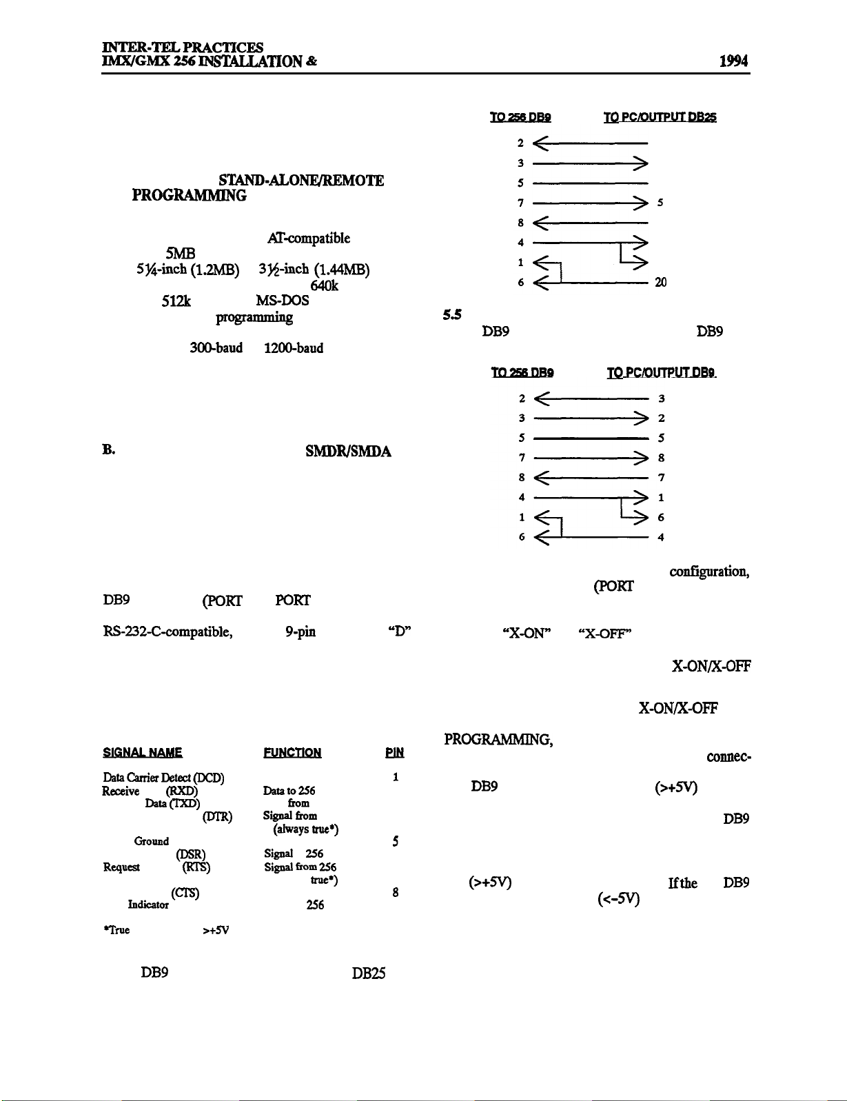
MAINTENANCE
. SPECIFICATIONS
Issue 1, November
5. ADDITIONAL SYSTEM
EQUIPMENT
A. PERSONAL COMPUTER (PC) FOR
ON-SITE OR STAND-ALONEIREMOTE
5.1
The device used for on-site or stand-alone/remote
programming must be an IBM AT+ompatible PC with a
minimum:
drive, Sy4-inch (1.2MB) or 3%~inch (1.44MB) double
sided/high density floppy disk drive, 640k RAM (with
minimum
graphics monitor. A grogramming mouse is optional (if
used, install on au unassigned COM port). For remote
maintenance, a 3CKLbaud or 1200-baud modem is also
needed. (See PRCGRAMMIN
tional information on remote system maintenance.) To
connect the PC to the RCPU Card for on-site program-
ming, refer to the following information.
PROGRAMMIN
OUTPUT DEVICE REQUIREMENTS
5.2 The on-site programming PC and the optional output device(s) for the Station Message Detail Recording
(SMDR) and Station Message Detail Accounting
(SMDA) features must have the characteristics de-
scribed in the following paragraphs.
5.3 To connect a PC or an output device to one of the
serial ports
Card, one end of the cable between the two must have an
connector. The other end of the cable must be compat-
ible with the output device. Consult the owner’s guide
for the device to verify that the pin functions are the
same as those shown in the following chart. Ifnecessary,
rewire the connector on the device to match the requirements.
Data (RXD)
Transmit
Data Terminal Ready (M-R)
Signal
Data Set Ready (DSR)
To Send (RIB)
Clear To Send (Cl-S)
Ring
= steady signal
5.4 The following cable can be created to connect one
of the
found on some PCs and output devices.
available memory on the hard disk
available),
3.3, and an EGA
G, page 5-3, for addi-
GPC AND
A or
B) on the RCPU
female
Signal to 256
Data
Reference Ground
Signal to 256
Signal to
to
(always
256
256
2
3
A
6
7
9
ports on the RCPU Card to the DB25 port
2
3
7
A
6
8
The following cable can be created to connect one
of the
ports on the RCPU Card to the
port
found on some PCs and output devices.
5.6 When the system is in the default conf@uration,
the 256 output device ports (PGRT A and PORT B) are
enabled for “software” handshaking. Most output devices are designed for software handshaking, which is
the use of “X-ON” and “X-OFF” characters to indicate
readiness to send or receive data. Refer to the device’s
operating manual to determine if it uses X-ON/x-OFF
characters.
5.7 If the device does not support X-GN/X-OFP characters, hardware handshaking may be enabled (see
page 5-169). When enabled for
hardware handshaking, signals are sent over the comrec-
tor pins to indicate readiness to send or receive data. The
256
port will send a logic true
on pin 4
(Data Terminal Ready) and pin 7 (Request To Send)
when it is ready to receive data. In addition, the 256 DB9
port will monitor pin 6 (Data Set Ready), pin 8 (Clear To
Send), or both (depending on how the 256 System is programmed) and will only send data if it receives a logic
true (>+5V) over the programmed pin(s).
port receives a logic false
to indicate that the
256 DB9
buffer on the attached device is full, it will not send data.
5.8 To meet Part 15 of FCC Regulations, all RS-232-C
cables must be equipped with ferrite beads. Two ferrite
“split” beads (two half beads) are installed on each cable
just below where the cable connects to the system. The
Page 2-31
Page 58

SPECIFICATIONS
1, November 1994
MAINTENANCE
beads help to reduce electromagnetic interference
NOTE: Each ferrite split bead, which is actually half of
a full bead, is ordered individually (see REPLACEMENT PARTS for the part number). Two split beads are
required to form one complete bead.
5.9 The on-site programming PC and SMDR/SMDA
output devices must communicate at 110, 300, 600,
or 19200 baud. (NOTE: The
19200 baud rate is for outgoing data only. The maximum programming baud rate is 9600.) System baud
rates are set independently in database programming.
include:
The data format must be 8 bit standard ASCII.
Parity is off (ignored).
Communication is full duplex.
There is one start bit and one stop bit.
5.10
The output devices, whether used for SMDR or
SMDA, must be able to print reports with a width of 80
characters. The devices must not have cables longer
than 50
C.
5.11
feet (15 meters).
SYSTEM
BATTERY BACK-UP
To provide back-up power in the event of an AC
power failure or brownout condition, the 256 System
power supply can have optional battery back-up using a
customer-provided uninterruptable power supply (UPS)
unit or standby power supply (SPS) unit.
5.12 It is recommended
a power supply unit with
the following characteristics be installed:
rating, which results in longer discharge rates; the volt-
age level remains the same as a single string.
5.14
Batteries must be fully charged when installed.
Charge each individually using a constant-voltage, current-limited charger with less than three percent ripple.
The charge voltage per cell must be set according to the
manufacturer’s specifications. Be careful not to damage
the batteries by overcharging them. For example, new
Globe brand batteries require 25 days of float voltage or
25-30
discharge cycles to attain full capacity. Initial ca-
pacity might only be 80 percent of rated capacity.
5.15
batteries should be of the same age and AH
rating. Some manufacturers date batteries by stamping
them with a date code. For example, Globe stamps their
batteries with a code such as
where 4 = the last
digit of year, 10 = the month, and B = the type of electrolyte. If a battery in a string needs to be replaced, the age
of the string will determine if a fresh battery can be added. If the string is two to three years old, adding a fresh
battery will reduce the life of the entire string. This is because a fresh battery will be overcharged, while the older batteries are undercharged.
5.16
Batteries may give off explosive and/or corrosive
gases. To reduce the effects of this gas, place the batteries (or battery compartment) in a well-ventilated room
and coat the terminals with an anti-corrosive agent.
Avoid storing batteries; they will self-discharge and
their capacity decreases with age. If you must store batteries, recharge them every six months. Recharge time
may vary depending on the charger’s current limit and
the battery’s state of charge.
D. ADDITIONAL INFORMATION
Sine wave output
Transfer time of less than 20 milliseconds
Output rating of 700 Watts (minimum needed for a
fully populated system; for smaller system require-
ments, contact Customer Support)
External or internal batteries
Low voltage cutoff circuit of 105VAC (minimum)
NOTE: Even if the power supply unit has the specifications listed above, it
be guaranteed that it will
work properly with the 256 System. Contact Customer
Support for a listing of approved IIPS/SPS power sup
plies and installation instructions.
5.13
Batteries comrected in series form a “string.“The
voltage of the string is equal to the sum of the individual
battery voltages. For example, five 6V batteries connected in series form a 30V battery pack. If desired, connect two strings in parallel to double the amp/hour
Page 2-32
5.17 If necessary, contact Inter-Tel Customer Support
for additional information on the optional equipment
listed below:
OPX Repeaters
and External Signaling Devices
Standby Power (system battery back-up)
Multi-Port Voice Mail
Facsimile Machine
Lightning and AC Surge Protection
Multiple External Paging Zones and
Speakers
Headsets
Playback Devices
l
Power Failuxe Transfer
Page 59

256
MAINTENANCE
SPECIFICATIONS
Issue 1, November
FIGURE
EXECUTIVE DIGITAL KEYSET (also called Executive Digital Terminal)
HEARING AID-COMPATIBLE
(HAC) HANDSET
INTERNAL
SPEAKER
LCD
SIX 8 LCD
SELEG
2 LCD FEATURE
DIRECTORY
SCROLL KEYS
14 FEATURE
KEYS
5 SPEED-DIAL
KEYS
PUSHBUTTON
KEYPAD
RING AND VOICE
VOLUME
CONTROLS
HANDSFREE
MICROPHONE
(underneath
edge)
NOTE: The keys are shown as they appear in the default key map configuration.
Page 2-33
Page 60
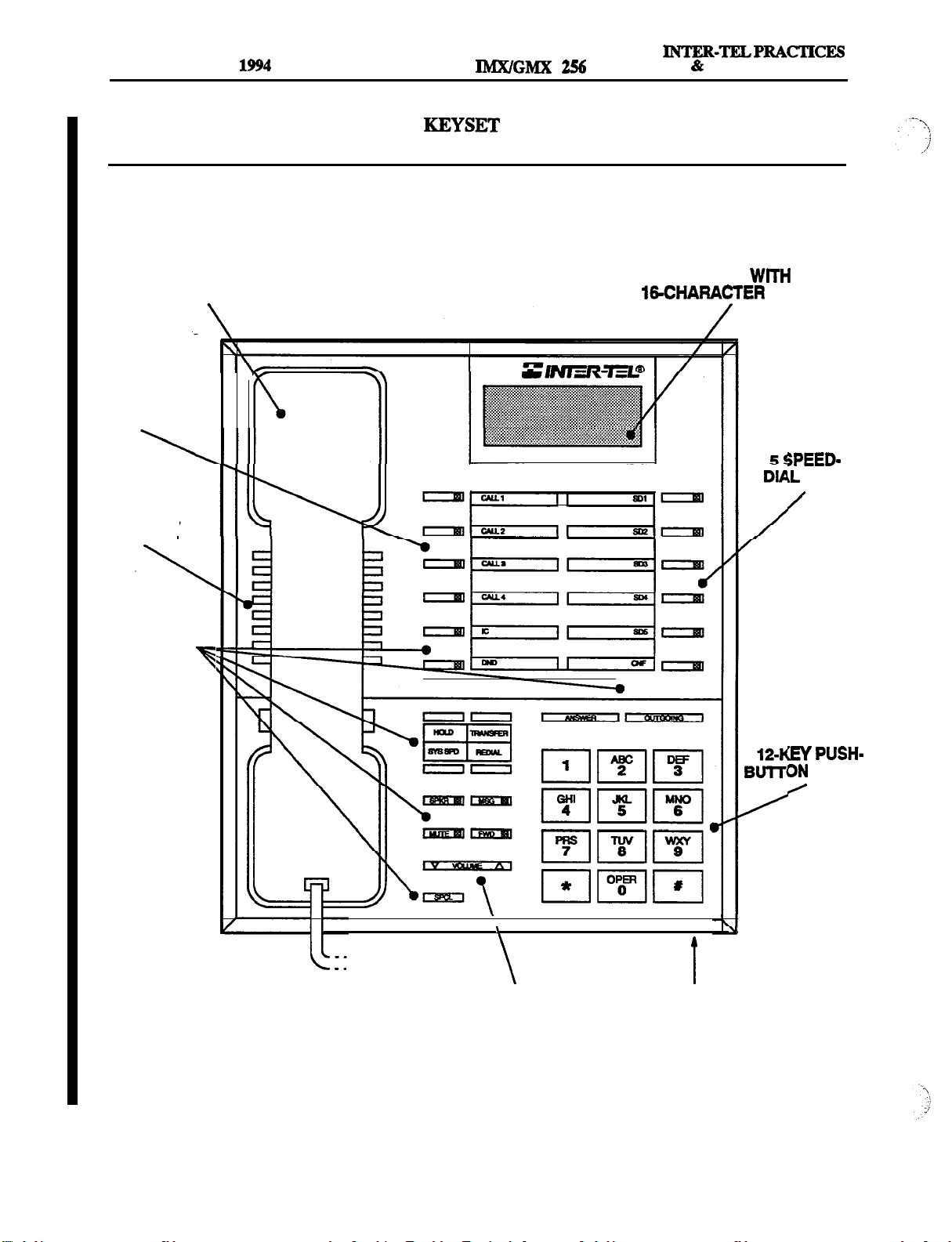
SPECIFICATIONS
Issue 1, November
INS-TION
MAINTENANCE
FIGURE
HEARING AID-COMPATIBLE
4 CALL KEYS
INTERNAL
SPEAKER
2-4. STANDARD DIGITAL
(HAC) HANDSET
(also called Standard Digital Terminal)
OPTIONAL LCD
TWO
LINES
KEYS
14 FEATURE
KEYS
RING AND VOICE
VOLUME
CONTROLS
KEYPAD
HANDSFREE
MICROPHONE
(underneath edge)
NOTE: The keys are shown as they appear in the default key map configuration.
Page 2-34
Page 61
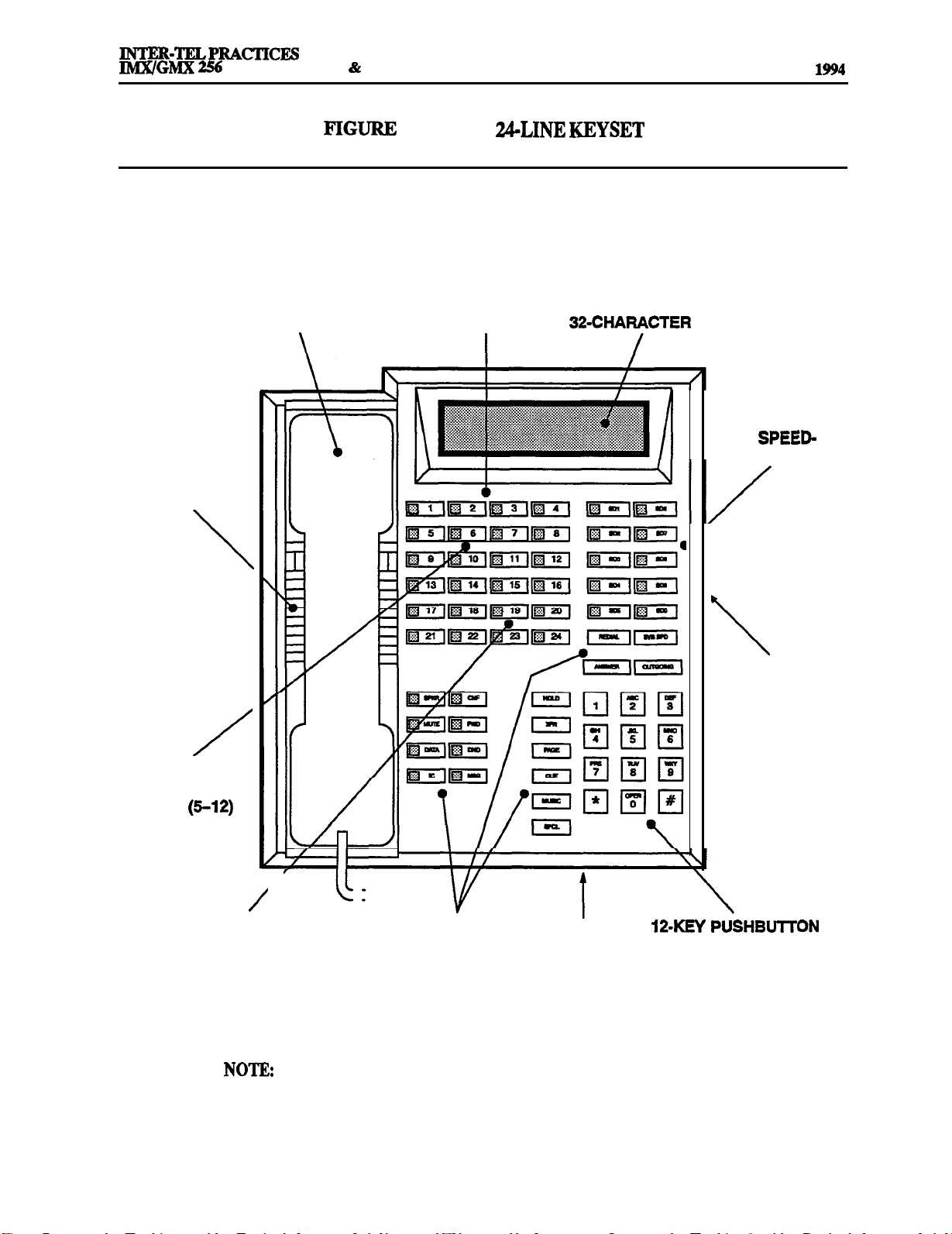
INSTALLATION
MAINTENANCE
SPECIFICATIONS
Issue 1, November
HEARING AID-COMPATIBLE
(HAC) HANDSET
INTERNAL
SPEAKER
2-5.
IMX
4 CALL KEYS
OPTIONAL
10 SPEED-
DIAL KEYS
8
STATION PRO-
GRAMMABLE
KEYS
12 UNDEFINED
KEYS (13-24)
RING AND VOICE
VOLUME
CONTROLS
(underneath edge)
18 FEATURE
KEYS
The keys are shown as they appear in the default key map configuration.
HANDSFREE
MICROPHONE
(underneath edge)
I
KEYPAD
Page 2-35
Page 62

SPECIFICATIONS
Issue 1, November 1994
INTER-TELPRACTICES
% MAINTENANCE
FIGURE 2-6.
HEARING AID-COMPATIBLE
(HAC) HANDSET
INTERNAL
SPEAKER
IMX 24-LINE AIM KEYSET
4 CALL KEYS
I
LCD
10 SPEED-
DIAL KEYS
8
STATION PRO-
GRAMMABLE
KEYS (5-12)
12 UNDEFINED
KEYS (13-24)
NOTE The keys are shown as they appear in the default key map configuration.
RING AND VOICE 18 FEATURE HANDSFREE
VOLUME KEYS MICROPHONE
CONTROLS
(underneath edge)
KEYPAD
Page 2-36
Page 63

MAINTENANCE
Issue 1. November 1994
FIGURE 2-7.
HEARING AID-COMPATIBLE
(HAC) HANDSET
INTERNAL
SPEAKER
IMX
4 CALL KEYS
OPTIONAL
LCD
10 SPEED-
DIAL KEYS
8
STATION PRO-
KEYS (5-12)
RING AND VOICE
VOLUME
CONTROLS
(underneath edge)
18 FEATURE
KEYS
The keys are shown as they appear in the default key map configuration.
HANDSFREE
MICROPHONE
(underneath edge)
I
PUSHBUTTON
KEYPAD
Page 2-37
Page 64

Issue 1,
INTERNAL
SPEAKER
November 1994
AID-COMPATIBLE
AC) HANDSET
256
FIGURE 2-8. IMX 12-LINE AIM
4 .CALL KEYS
LCD
10 SPEED-
DIAL KEYS
8
STATION PRO-
GRAMMABLE
KEYS (5-12)
KEYPAD
RING AND VOICE 18 FEATURE
VOLUME KEYS
CONTROLS
HANDSFREE
MICROPHONE
(underneath edge)
NOTE: The keys are shown as they appear in the default key map configuration.
Page 2-38
Page 65

INTER-TELPRACTICES
HEARING AID-COMPATIBLE
(HAC) HANDSET
INTERNAL
SPEAKER
FIGURE 2-9. IMX &LINE
4 CALL KEYS
SPECIFICATIONS
1. November 1994
4
STATION PRO-
GRAMMABLE
NOTE: The keys are shown as they appear in the default key map configuration.
14 FEATURE
KEYS
HANDSFREE
MICROPHONE
(underneath edge)
RING AND VOICE
VOLUME
CONTROLS
(underneath edge)
KEYPAD
Page 2-39
Page 66

SPECIFICATIONS
Issue 1, November 1994
256
INTER-TELPRACTICES
MAINTENANCE
FIGURE 2-10. IMX &LINE AIM KEYSET
HEARING AID-COMPATIBLE
(HAC) HANDSET
INTERNAL
SPEAKER
LCD
4 CALL KEYS
4
STATION PRO-
GRAMMABLE
NOTE: The keys are shown as they appear in the default key map configuration.
RING AND VOICE
VOLUME
CONTROLS
FEATURE
KEYS
HANDSFREE 12-KEY PUSHBUTTON
MICROPHONE KEYPAD
(underneath edge)
Page
Page 67

FIGURE
HEARING AID-COMPATIBLE OPTIONAL
4
(HAC) HANDSET
INTERNAL
SPEAKER
CALL KEYS
Issue 1, November 1994
8
STATION PRO-
GRAMMABLE
KEYS (5-12)
12 UNDEFINED
KEYS
(13-24)
10 SPEED-DIAL
KEYS
RING AND VOICE
VOLUME
CONTROLS
KEYPAD MICROPHONE
HANDSFREE
18 FEATURE
KEYS
The keys are shown as they appear in the default key map configuration.
Page 2-41
Page 68

. . . .
:’
Page 69

256 INSTALLATION & MAINIENLINCE
SPECIFICATIONS
Issue 1. November 1994
FIGURE 213.
HEARING AID-COMPATIBLE
(HAC) HANDSET
INTERNAL
SPEAKER
4
CALL KEYS
ACTER LCD
4
STATION PRO-
GRAMMABLE
8 SPEED-DIAL
RING AND VOICE 12-KEY
VOLUME PUSHBUTTON MICROPHONE
CONTROLS KEYPAD
HANDSFREE
14 FEATURE
KEYS
NOTE: The keys are shown as they appear in the default key map configuration.
Page 2-43
Page 70

SPECIFICATIONS
Issue 1, November 1994
256
MAINTENANCE
FIGURE 2-14. DIGITAL DIRECT STATION SELECTION/BUSY LAMP FIELD
UNIT
60 DSS/BLF AND/OR
FEATURE KEYS
Page
Page 71

INTER-TELPRACTICES
256 INSTALLATION & MAINTENANCE
SPECIFICATIONS
Issue 1, November 1994
FIGURE 2-15.
60 DSSIBLF KEYS
IMX
UNIT
Page 2-45
Page 72

Issue 1, November 1994
INTER-TELPRACTICES
256 INSTALLATION
MAINTENANCE
FIGURE 2-16.
60 DSS/BLF
AND/OR
FEATURE KEYS
Page
Page 73
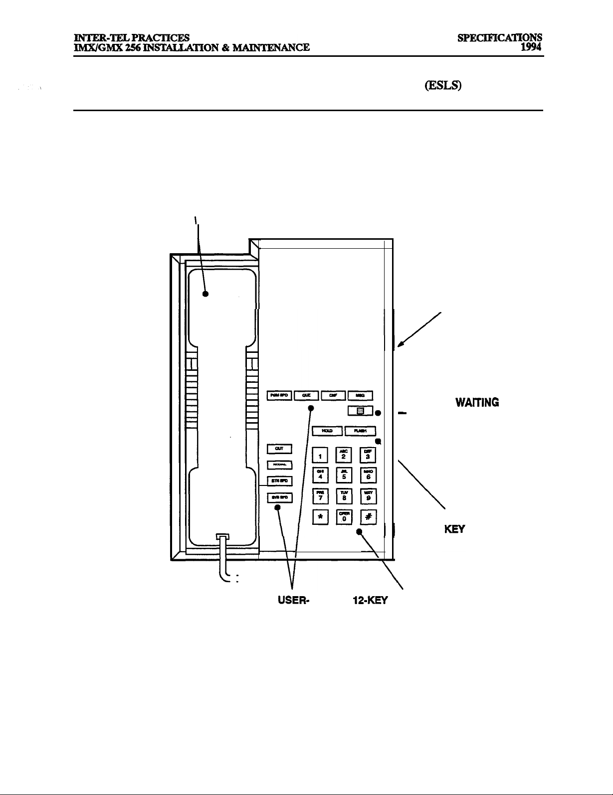
FIGURE 2-17. ENHANCED SINGLELINE SET
HEARING AID-COMPATIBLE
(HAC) HANDSET
Issue 1, November
RING VOLUME
CONTROL
(underneath edge)
MESSAGE WAlTlNG
LAMP
TIMED HOOKFLASH
9
PROGRAMMABLE KEYPAD
FEATURE KEYS
NOTE: The keys are shown as they appear in the default key map configuration.
Page 2-47
Page 74

SPECIFICATIONS
Issue 1,
November
256 INSTALLATION & MAINTENANCE
INTER-TELPRACTICES
HEARING AID-COMPATIBLE
(HAC) HANDSET
SINGLELINE INSTRUMENT
PUSHBUTTON
KEYPAD
4
PROGRAMMABLE
FEATURE
RING VOLUME
CONTROL
(underneath edge)
TIMED HOOKFLASH
NOTE: The keys are shown as they appear in the default key map configuration.
Page 2-48
Page 75

256
INSTALLATION
1, November 1994
1. Introduction
2. System Installation Outline
3.
.
Establish Suitable Environmental Conditions For The System
B. Assemble The Necessary Tools Aud Supplies
.
Plan Station Locations And Types Of Station Instruments
D. Assemble The Optional Equipment
4. Station Cabling
Running Cable
B. Terminating The Cables At Station Locations
.........................................................
............................................ 3-2
Checklist
............................................. 3-3
.......................... 3-3
..................................
...................................................... 3-6
................................................... 3-6
.........................
5. Assembling The Main Distribution Frame (MDF) Backboard
.
Connecting The Trunk Cables To The MDF
B. Connecting
Spans To The MDF
.................................. 3-17
C. Connecting Station Cables To The MDF
D. Station Loop Resistance Test
....................................... 3-29
E. Connecting Optional Off-Premises Extensions (OPXs)
.
Connecting The RCPU Card To The MDF
G. Connecting Optional
H. Connecting
256 Systems Together Using
6. Equipment Cabinet Installation
A. Unpack The Equipment
Alarm Relay Devices To The MDF
........................................ 3-35
........................................... 335
B. Check The Equipment Cabinet
.
Install The Power Supply Modules
D. Install The Circuit Cards
.......................................... 3-44
E. Check The Circuit Card Installation
F.
Complete The Equipment Cabinet Installation
.................................. 3-39
.................................
..........................
............................. 3-21
..................
............................ 3-30
Cards
.................
.........................
........................
...........
..............
...............
.............
3-2
3-3
3-4
3-7
3-9
3-30
3-33
3-34
3-35
3-61
3-61
7. Station Installation ...................................................
.
IMX 256 Digital Keyset Installation
B.
IMX 256 Analog Keyset Installation
C. GMX-256 Analog Keyset Installation
D. IMX 256 Digital DSS/BLF Unit Installation
E.
IMX 256 Analog DSS/BLF Unit Installation
.
GMX-256 Analog DSS/BLF Unit Installation
G. Attendant Computer Console Installation
H. Single-Line Set And Playback Device Installation
8. SMDR/SMDA Output Device Installation
9. External Paging Equipment Installation
10. External Music Source Installation
11. Preventative Maintenance
12. Post-installation Checklist
............................................. 3-99
............................................. 3-100
.................................
................................. 3-71
................................ 3-81
...........................
.......................... 3-92
......................... 3-93
............................ 3-93
...................... 3-95
................................
.................................
...................................... 3-99
Page 3-l
3-62
3-62
3-90
3-98
3-98
Page 76
INSTALLATION
Issue 1, November 1994
256 INSTALLATION
MAINTENANCE
1.
1.1 This section describes the recommended proce-
dures for installing the 256 System hardware. Refer to
for hardware descriptions.
2. SYSTEM
2.1 System installation is performed in the following
order. Detailed instructions and figures for each step are
located throughout the J.NSTAL,LAlTON section.
Plan the installation, including the equipment
cabinet and main distribution frame (MDF) location, station locations, cable runs, and optional
equipment.
Run cables to the keysets, analog Direct Station
Selection/Busy Lamp Field
Attendant Computer Consoles, single-line sets,
and playback devices. Run wiring to any optional equipment, such as power failure transfer
external paging equipment, general
signaling devices, music sources, etc.
Units,
Perform the station loop resistance test for each
station cable.
Assemble the equipment cabinet.
the system power supply modules in the
power supply chassis.
Install the circuit cards in the equipment cabinet
and connect them to the cables
that run from the MDF blocks (or MDF modular
jack assemblies).
Install the station instruments and any optional
station equipment, such as headsets, handset amplifiers, and Data Port Modules.
Install any optional system equipment, such as
output device(s) for station message detail
recording (SMDR) and station message detail
accounting (SMDA), external paging network,
external music source(s), voice mail, etc.
Refer to the
(13)
manual to cont&ure and program the system.
cords)
Terminate the station cables on modular jack assemblies at the station locations.
Mount the MDF backboard and assemble the terminal blocks on the backboard. If any
are to be installed, terminate them on eight-con-
ductor modular jack assemblies at the MDF.
NOTE: The
the standard
the
Card. However, in certain situations (e.g.,
when using an external CSU equipped with a
DB15 connector), it may be more convenient to
use the card’s optional DB15 connector instead.
Refer to page 3-20 for more information.
Connect the trunks, station cables, and circuit
card cables to the corresponding terminal blocks
(or, for
span is typically connected to
modular jack provided on
modular jack assemblies).
spans
NOTICE
This LUWGMX256 Installation and
Manual
on the proper installation practices for the 256 Sys-
tem. This manual does
instructions for premises wiring practices as dictated by the National Electrical Code, which includes, but is not limited to, cable layouts, cable
installation, AC power installation, proper AC
grounding, eliminating or preventing external inter-
ferences (including, but not limited to, RFI, EMI,
lightning, AC power disturbances, static discharge),
and other telephony practices standard within the in-
dustry. Cable installers, electricians, and field technicians are expected to be properly trained and, if
applicable, licensed in their trade practices.
256
tance.
certified field technicians
provide stepby-step
is required for technical assis-
Page 3-2
Page 77

256
INSTALLATION &
3.
CHECKLIST
3.1 To make installation easier, use the checklist on
the following pages when preparing to install the sys-
tem. (Hardware specifications are included in the
CONDITIONS FOR
THE SYSTEM
Locate the equipment cabinet within 5 feet (1.5 me-
ters) of an isolated, dedicated,
single-phase commercial power
source.
NOTE: This musf be an isolated, dedicated AC cir-
cuit for proper operation. All three wires (power,
neutral, and ground) must be run separately from the
outlet to the breaker panel without being bonded to
any other wire or circuit. DO
NOT
plug any other
equipment into this outlet. To maintain the protection provided by the isolated, dedicated circuit, the
length of the AC power cord limits the distance between the power supply and the outlet; DO
an extension cord. Also, to protect the system from
AC voltage surges, a surge/spike protector is
supplied with the system (refer to page 2-9 for speci-
fications).
Select the equipment cabinet location to minimize
cable run length. Station instruments connected to
the system must not exceed the limits (using
24AWG wire) listed in the table on page 3-29. The
ohm values are loop measurements; feet
ues are the maximum one-way measurements from
the equipment cabinet.
Temperature
Equipment Cabiiet o”to
Temperahue
Station Instruments
Relative Humidity 5% to 95% 5% to 95%
Altitude
32” to 113’ F
45°C
up to 10,ooo ft.
to 185’ F
to 185” F
NOTE: It is recommended that the maximum oper-
ating temperature (as stated above) never be exceed-
ed. Therefore, when installing the equipment
cabinet and station instruments, allow a sufficient
margin for error in case of air conditioning failure,
routine maintenance, plant shutdown, etc.
a general rule, if conditions are suitable for office personnel, they are also suitable for all equipment and
station instrument operation. A properly controlled
environment will help to extend the operating life of
the equipment.
safety specification
telephone equipment:
Never install telephone wiring during a lightning
storm.
Never install telephone jacks in wet locations unless
the jack is specifically designed for wet locations.
Never touch uninsulated telephone wires or termi-
nals unless the telephone line has been disconnected
at the network interface.
Use caution when installing or modifying telephone
lines.
Do not expose the equipment cabinet location to di-
rect sunlight, high humidity, heat, dust, or strong
magnetic fields (such as those generated by heavy
motors and large copy machines).
The MDF requires a 4 x 8-foot (1.2 x
plywood backboard. This should provide
sufficient room for all blocks and peripheral equip
ment.
For cooling purposes, provide ample air space
around the equipment cabinet assembly (minimum
one foot on all sides). Other than the programming
PC, do not place or store items on top of the equip
ment cabinet.
The SMDR/SMDA output device(s) must not have
cables longer than 50 feet (15 meters).
Locate the equipment in a climate-controlled room
with the following environmental conditions:
Page 3-3
B.
ASSEMBLE THE NECESSARY TOOLS
AND SUPPLIES
Industry-standard,
twisted cable to run
instruments, including:
three-pair (six-conductor)
the MDF to all station
analog
Units, Attendant Computer Consoles, ESLSs, SLIs,
single-line DTMF sets, and playback devices. (For
exceptions, see the NOTE on page 3-6.)
Six-conductor modular jack assemblies for all sta-
tion instruments. (For exceptions, see the NOTE on
page 3-6.)
A high-impedance digital multimeter to check the
power supply and ensure correct wiring of the modular jack assemblies. Multimeter accuracy must be
or better.
Standard terminal blocks
type) and bridg-
ing clips for constructing the MDF.
Page 78
INSTALLATION
Issue 1, November 1994
256
INTER-TELPRACTICES
& MAINTENANCE
Industry-standard,
cable for comtecting the
terminal blocks to the circuit cards iu the
equipment cabinet.
Industry-standard, cross-connect wire may be need-
ed for certain applications.
ommended non-conducting, plastic covers) and a
connecting machine.
Ferrite beads for all station, trunk, and RS-232-C
cables. (Refer to SPECIFICATIONS, page 2-4.)
Gas discharge tubes with silicon avalanche suppres-
sors for lightning protection on the CO, DID, OPX,
Grounding terminal and 1OAWG wire for grounding
the equipment cabinet.
Standard
telephone hand tools and the mounting
hardware for the MDF backboard, trunk and station
blocks, modular jack assemblies, etc.
PC for customizing the database
(refer to page 2-31 for specifications).
3.2
the type of
spans are
to
be installed: Depending on
terminationused by the telephone company (telco) and how close it is to the MDF, the following
tools and supplies are also needed.
NOTE: The
dard
span is typically connected to the stan-
modular jack provided on the
Card.
However, in certain situations (e.g., when using an external CSU equipped with a DB15 connector), it may be
more convenient to use the card’s optional DB15 connector instead. Refer to page 3-20 for more information.
For Tl spans terminated on
jacks near the
Four-pair, non-reversing, mod-to-mod line cords
(one for each
For Tl spans terminated on
the MDF (see
span installed).
jacks away
3-9 on page 3-18):
For Tl spans terminated on an
on page 3-19):
block (see
Eight-conductor modular jack assemblies (one for
each
span installed).
Four-pair, non-reversing, mod-to-mod line cords
(one for each
-enough to extend from each telco termi-
cable
nation to the MDF (see page
span installed).
for cable specifi-
cations).
C.
PLAN STATION LOCATIONS AND TYPES
OF STATION INSTRUMENTS
NOTE: For information on the GX and GMX station
instruments, refer to appendixes A and B in the back of
this manual.
Prepare a cable identification plan using station
cir-
cuit numbers; do not use extension numbers (see
page 3-6 for details).
The IMX 256
System has the capacity for
up to 256 keysets if using the new digital keysets or
IMX AIM keysets, which can be installed two
to a circuit. The GMX-256 System has the capacity
for up to 128 keysets. Refer to SPECIFICAI’IONS,
starting on page 2-21, for a listing of the available
mum station capacities. Excluding nondisplay only
models, all standard keysets can be converted to display
by installing optional Liquid Crystal
Display (LCD) Units (see REPLACEMENTPARTS
for part number).
NOTE: The equipment cabinet has 16 slots for station and trunk cards. The
of stations
and trunks available depena3 on the number and
type of cam& station hsmmentts,
equipped with
Units: Up to 50
Units. Digital units are
and power supply
circuits can be
powered by their own AC transformers and do not
require a DKSC circuit that is separate from the key-
set’s circuit. Each analog unit requires one KSC or
KSC-D circuit and its own cabling. As many as four
analog units can be installed on a single XSC.
Eight-conductor modular jack assemblies (two for
each
span installed).
Four-pair, non-reversing, mod-to-mod line cords
(two for each
cable -enough to extend from each telco RJ48C
jack to the MDF (see page
span installed).
for cable specifica-
tions).
Page 3-4
Attendant Computer Consoles: If desired, up to
128 Attendant Computer Consoles can be installed
on the system. The consoles are connected to KSC or
KSC-D circuits.
NOTE: For additional information on the Attendant
Computer Console, along with detailed installation
and programming instructions, refer to the manual
included with the console.
Page 79

INTER-TELPRACTICES
INSTALLATION
Issue 1. November
Sets: Up to 240 single-line sets can be
installed on the system. They can be Enhanced
Single-Line Sets @SLSs), Single-Line Instruments
Playback devices can be used in
place of single-line stations. They are especially
as hunt group overflow/announcement stations and automated attendant stations. (Refer to
page 2-30 for specifications.)
D.
THE OPTIONAL EQUIPMENT
Headsets for keyset stations and handset amplifiers
for keyset stations or single-line set stations.
Digital keyset Personal Computer Data Port Mod-
ules (PCDPMs) for using Off-Hook Voice Announce
(OHVA) features, and for installing a digital
BLF Unit and/or an optional Modem Data PortMod-
ule.
Digital keyset Modem Data Port Modules (MDPMs)
for connecting modem-equipped data devices or
single-line sets.
I
Analog
Data Port Modules for hooking up
either modem-equipped data terminals or loud ringing adapters and external signaling devices.
if necessary. (Refer to page 2-30 for specifications.)
Up to two external music sources.
External paging speakers and amplifier(s). (Refer to
the NOTE and CAUTION on page 2-6.)
General signaling devices.
Power failure transfer equipment (customer-pro-
vided PFI’relay card, card mounting case, and external power source).
Electronic equipment (alarms, lights, etc.) to
nect to the night transfer relay and/or the
con-
alarm
relays.
For on-site or stand-alone/remote system program-
ming, an IBM AT-compatible personal computer
with a minimum: 6 megabytes (MB) available
memory on the hard disk drive,
double sided/high density
(1.2MB) or
floppy disk drive, 640k RAM (with minimum 512k
available), MS-DOS 3.3 (or 5.0,6-O, or 6.2), and an
EGA graphics monitor. A programming mouse is
optional (if used, install on an unassigned COM
port). For remote maintenance, a
or
more information.)
cables longer than
output device(s) must not have
feet
meters). (See page
2-31 for specifications.)
System battery back-up
power
supply or standby power supply. (Refer to page 2-32
for specifications.)
Doorbox equipment. (Refer to page 2-32.)
Voice mail equipment. (Refer to page 2-32.)
Facsimile machine. (Refer page 2-32.)
Talkback speakers and external control unit. (Refer
to page 2-32.)
Page 3-5
Page 80

Issue 1, November 1994
INSTALLATION
MAINTENANCE
4.
CABLING
4.1 Floor plans should be developed to aid in proper
station cabling in a star (home run) configuration from
the equipment cabinet. The cables are run from the station locations to the station blocks at the MDF. Refer to
page 2-4 for cabling requirements.
4.2 Both ends of each cable should be labeled with the
station’s circuit number (hardware address). The circuit
number
designates the card’s position in the
equipment cabinet (X = 1-16) and the circuit positionon
the card
= 1-16 for DKSCS, Y = l-8 for KSCs, KSC-
and IDES, Y = 1-16 for SLCs). For example, circuit
number 4.6 identifies the sixth circuit on the card installed in slot number four.
NOTE: When IMX
dual-circuit
are installed two to a circuit, the circuit number is separated
into two parts (A and B) in database programming (e.g.,
circuit
43
and 4.6B).
When the system is first powered up, the default
configuration is used to assign extensionnumbers to the
station circuits. On IMX 256 Systems, card slots l-4 are
considered KSCs or RSC-Ds, slots 5-6 are DKSCs, slots
7-8 are unassigned, slots 9-12 are
and slots
13-16 are LGCs. On GMX-256 Systems, card slots l-8
are considered KSCs or KSC-Ds, slots 9-12 are SLCs,
and slots 13-16 are LGCs. Changes to the default configuration can be made through database programming.
Refer to PROGRAMMIN G, page 5-170, for more information.
4.4
The system assigns extension number 100 to sta-
tion circuit 1.1, extension number 101 to station circuit
1.2, and so on to match the initial configuration. Circuit
1.1 is equipped as the primary attendant’s keyset when
the system is in the default configuration. Through database programming the circuits can be assigned differ-
ent extension numbers and/or be changed to four-digit
extension numbers. Refer to PROGRAMMING, page
5-58,
for more information.
NOTE: “B” circuit
extension numbers
keysets do not have
assigned one in database pro-
A.
NOTE: It is recommended that three-pair twisted cable
and six-conductor modular jacks be used for all station
connections. This allows the various types of station instruments to be easily interchanged, if necessary. However, digital
single-line
sets, and playback devices can be installed using one-
pair twisted cable and four-conductor modular jacks. (If
three-pair cable is used for wiring digital
single-line sets, and playback devices as recommended,
extra terminal blocks and the use of crossconnect wiring techniques are required.)
4.6 From the MDF location, run industry standard,
three-pair (six-conductor) twisted (24AWG, level-l or
better) cable to keysets, analog DSS/BLF Units, Atten-
dant Computer Consoles, single-line sets, and playback
devices. Follow these guidelines:
Install proper type cable for the application according to the National Electrical Code and local building
Avoid cable runs parallel to fluorescent light fixtures
or AC lines not in conduit. If these obstacles are unavoidable, run the cables across them at right angles.
Do not run station cables inside electrical conduit already occupied by AC power cable. (To do so is a
violation of the National Electrical Code.)
Do not run cables near equipment with electric motors or through strong magnetic fields, such as those
generated by large copy machines, arc welding
equipment, heavy motors, etc.
Do not place station cables where they can be
stepped on or where they can be rolled over by office
furniture.
Ifusingmulti-pair (e.g., 25-pair)
ple station locations, do not include AC-ringing
single-line sets, AC-ringing auxiliary equipment, or
trunks in a cable being used for analog keysets, At-
tendant Computer Consoles, or analog
Units. Stations using analog keyset circuits should
be routed in separate multi-pair cable runs.
4.5
Each analog
Unit requires a KSC or
circuit and cabling that is separate from the key-
set’s circuit and cabling. If50 keyset circuits are used for
analog DSS/BLF Units, 50 fewer analog keysets and/or
Attendant Computer Consoles can be installed. Up to
four units can be installed on a single Reyset Card.
Page 3-6
Do not exceed the loop limit measurements (using
24AWG wire) for the station cable lengths as out-
lined in the table on page 3-29. The ohm values are
loop measurements; feet (meter) values are the max-
imum one-way measurements from the equipment
cabinet.
Page 81

4.7
256
Since the
256 System utilizes digital voice
MAINTENANCE
and data transmission between the digital keysets and
the equipment cabinet, there are some additional digital
keyset-only cabling requirements:
l Do not use shielded cable, and do not use cable
smaller than 24AWG.
l
tion.
l Unlike analog
the digital
do not
need to be routed in separate multi-pair cable runs.
For example, if using
cable runs to multiple
station locations, it is acceptable to include single-
line sets, auxiliary equipment, and trunks in a cable
being used for digital keysets.
INSTALLATION
Issue 1, November 1994
B.
THE CABLES AT
Digital
4.8
Terminate the digital keyset station cables on four-
or six-conductor modular jack assemblies at the station
4.9 Do not mount the assemblies on the wall at this
time; they will be wall mounted later when the station
instruments are installed. Refer to Figure 3-l below for
a wiring diagram.
If the tip and ring is reversed when installing a
digital keyset, the keyset will not function.
FIGURE 3-l.
RING
DIGITAL
I
FOR DIGITAL KEYSETS
USING FOUR-CONDUCTOR JACKS
MODULAR JACK ASSEMBLY WIRING
RING
I
TIP
FOR DIGITAL KEYSETS
USING SIX-CONDUCTOR JACKS
Page 3-7
Page 82

Issue 1, November 1994
Analog Station Instruments
4.10
Terminate the analog
analog
Unit, Attendant Computer Console, single-line set, and
playback device station cables on six-conductor modular jack assemblies at the station locations. (For exceptions to this, refer to the NOTE following section A on
the previous page.)
Do not mount the assemblies on the wall at this
time; they will be wall mounted later when the station
instruments are installed. Refer to Figure 3-2 below for
a wiring diagram.
256 INSTALLATION & MAINTENANCE
If the power pair
stalling a
INTER-TELlPRACTICES
CAUTION
is reversed, in-
Attendant Computer Console,
or DSS/BLF Unit will open the fuse or associated
thermistor on the
Card. If the card has a
fuse, this affects operation of all station instruments connected to that card. If tip and ring (W/
BL,
is reversed for DC-ringing single-line
sets, the instrument may ring continuously.
FIGURE 3-2. ANALOG
I
MODULAR JACK ASSEMBLY WIRING
FOR ANALOG
ATTENDANT COMPUTER CONSOLES,
AND ANALOG
UNITS
WIG
FOR SINGLE-LINE SETS
AND
PLAYBACK DEVICES
NOTE: The
and
conductors for the types of stations are reversed. If the type of station
instrument is changed, the modular jack must be rewired.
Page 3-g
Page 83

INSTALLATION
5.
ASSEMBLING THE MAIN
MAINTENANCE
DISTRIBUTION FRAME
BACKBOARD
5.1 The main distribution frame (IUDF) is the point at
which the station instruments, trunks, and auxiliary system equipment are connected to terminal blocks (or, in
the case of
lar jack assemblies are used instead). These terminal
blocks (or modular jacks) are then connected to the 256
System. It is extremely important that the connections
be made careffilly and accurately.
this manual outlines basic one block to one card installation using bridging clips. However, it is quite acceptable, and in some situations more
additional blocks and then moss connect between them.
5.2 Assemble the MDF as follows:
(1) Mount at least a 4
tion. (Depending on the number of stations and
trunks to
necessary.)
(2)
Attach the
plywood backboard. Refer to Figure 3-3 on the
next page for a sample MDF block layout and
cable assignments. Blocks include:
l
spans and optional
To simplify the MDF installation instructions,
x
g-inch plywood backboard at the MDF loca-
installed, a larger backboard may be
Up to 15 blocks for connecting CO trunks and
the
cables for the Loop/Ground Start
equipment, modu-
to use
x
terminal blocks to the
INSTALLATION
Cards (LGCs) and/or the Loop Start Cards
Up to 15 blocks for connecting DID trunks
and the
Up to 16 blocks for connecting station cables
and the
Digital
analog keysets, analog DSWBLF Units, and
Attendant Computer Consoles; Single-Line
Cards
back devices; and Inward Dialing Cards
for off-premises extensions and/or
on-premises single-line sets and playback
devices.
If, as recommended, three-pair cable
is used for wiring single-line sets and play-
back devices, extra terminal blocks and the
use of cross-connect wiring techniques are
required.
One block for connecting the RCPU Card
cable and cables for music sources, paging
equipment relay control, power failure transfer equipment, night transfer equipment,
general signaling devices, etc.
(3)
If any
ing devices are to be installed, attach eight-conductor modular jack assemblies to the MDF as
required. (For complete information on installing
spans or any optional
spans, refer to page 3-17.)
cables for the Inward Dialing
cables for the station cards
Cards
for single-line sets and play-
for digital
alarm signal-
Page 3-9
Page 84
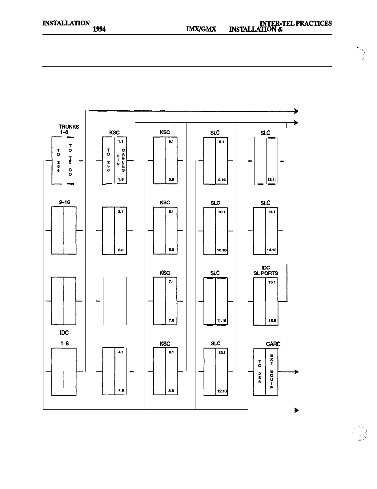
Issue 1, November
256
MAINTENANCE
FIGURE 3-3. SAMPLE MDF BLOCK LAYOUT AND CABLE ASSIGNMENTS
TO CENTRAL
OFFICE
LGC OR LSC
CO
L
LGC OR LSC
CO TRUNKS
KSC
21
13.1
14.1
TO STATIONS
EMC
E&M TRUNKS
1-4
DID TRUNKS
28
KSC
3.1
3.8
I
KSC RCPU
7.1
7.8
6.1
11.1
14.16
TO EXTERNAL
EQUIPMENT
CABLES
TO 256
Page 3-10
Page 85
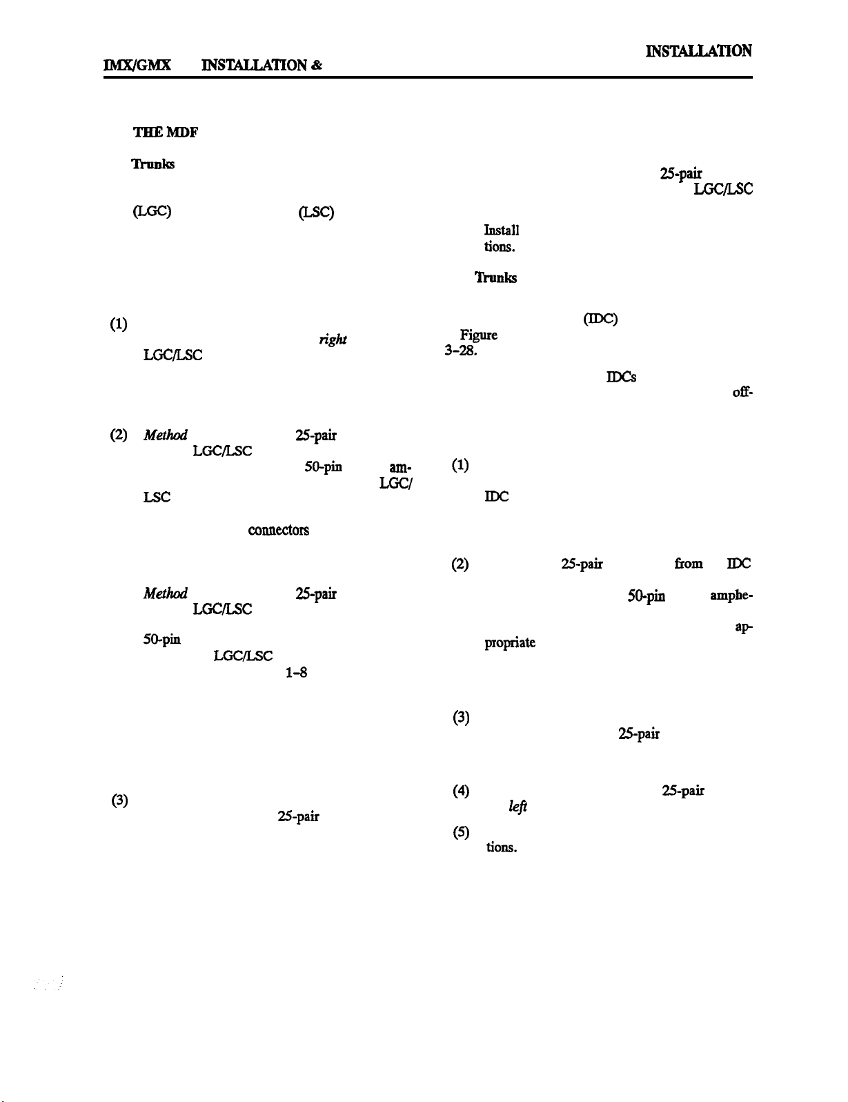
INTER-TELPRACTICES
256
A.
CONNECTING THE TRUNK CABLES TO
MAINTENANCE
co
5.3
Connect the CO trunks and Loop/Ground Start
Card (LGC) and/or Loop Start Card
cables as outlined below. Note that step 2 mentions two installation
methods. Although the first method is more flexible, the
second method can be used to minimize the number of
terminal blocks that are used. Refer also to Figures 3-5
and 3-6 on the following pages.
Cross connect the CO trunks from the telephone
company RJ-type blocks to the righz side of the
blocks.
NOTE: For additional lightning protection, see
paragraph 5.6 on the next page.
A: Using enough
from the
blocks to the cards, make the
cable to run
termination cables. Attach a %)-pin female am-
phenol-type connector to one end of each
cable. Label each connector and cable end
with the appropriate slot number (for example,
SLOT-15). These
will be
attached to
the cards after they are installed in the equipment
cabinet.
B: Using enough
from the
blocks to the cards, make the
cable to run
special termination cables. Attach up to three
female amphenol-type connectors to one
end of each
3-6.
Connect CO trunks
cable as shown in Figure
to one connector,
trunks 9-16 to another connector, trunks 17-24
to a third connector, and so on for each cable.
Label each connector with the appropriate slot
number (for example, SLOT-E). These connectors will be attached to the cards after they are installed in the equipment cabinet.
Using standard electrical tape, tape two ferrite
split beads around each 25-pair cable just below
the amphenol-type connector (as shown in Figure
3-4
on the next page).
Issue 1,
November 1994
NOTE: Ferrite beads must be installed to meet
Part 15 of FCC regulations. Refer to REPLACEMENT PARTS for the part number.
(4) Terminate the other end of each
cable on
the left side of the corresponding
block.
(5) Install
bridging clips to complete the connec-
DID
5.4
Connect the Direct Inward Dialing (DID) trunks
and Inward Dialing Card (RX!) cables as follows. Refer
to
3-7 on page 3-15 and Figure 3-19 on page
NOTE: Resides DID trunks, IDCs can also be used to
install single-line sets, playback devices, and
premises stations. Any combination using the eight cir-
cuits on the card is possible. Refer to pages 3-21 to 3-28
for station installation instructions.
Cross connect the DID trunks from the telephone
company RJ-type blocks to the right side of the
blocks.
NOTE: For additional lightning protection, see
paragraph 5.6 on the next page.
Using enough 25-pair cable to run from the IDC
blocks to the Inward Dialing Cards, make the termination cables. Attach a 50-pin female amphe-
nol-type connector to one end of each IDC cable.
Label each connector and cable end with the
These connectors will be attached to the Inward
Dialing Cards after the circuit cards are installed
in the equipment cabinet.
Using standard electrical tape, tape two ferrite
split beads around each 25-pair cable just below
the amphenol-type connector (as shown in Figure 3-4 on the following page).
Terminate the other end of each
the
side of the corresponding IDC block.
cable on
Install bridging clips to complete the connec-
Page 3-11
Page 86

Issue 1,
November
256
INSTALLATION
INTER-TELPRACTICES
MAINTENANCE
5.5 Connect E&M trunks and E&M Card
cables as follows. Refer to Figure 3-g on page 3-16.
(1)
Cross
phone company RJ-type blocks to the
of the
the E&M trunks from the tele-
side
blocks.
NOTE: For additional lightning protection, see
paragraph 5.6.
(2)
blocks-to the
cables. Attach a
Cards, make the termination
female amphenol-type
connector to one end of each EMC cable. Label
each connector and cable end with the appropriate slot number (for example, SLQT-16). These
connectors will be attached to the -E&M Cards
after the telecommunication cards ‘are installed
in the equipment cabinet.
(3) Using standard electrical tape, tape two ferrite
split beads around each
cable just below
the amphenol-type connector (as shown in Figure 3-4 below).
(4) Terminate the other end of each
the
side of the corresponding
(5)
Install bridging clips to complete the
Lightning
Protection
cable on
block.
5.6 For additional lightning protection, install gas discharge tubes with silicon avalanche suppressors to
ground (grounding rod or copper, cold water pipe) on
each CO, DID, E&M, and OPXtrunk. This must be done
external to the system. Each gas discharge tube is installed directly between the telephone company RI-type
block and the system’s CO/DID/E&M/OPX input. This
protection should give energy absorption and filter low-
level surge potentials. (For installation instructions and
specific recommendations, contact Customer Support.)
5.7 Also, in areas with frequent occurrences of lightning, it is recommended that the cable between the telephone company RJ-type blocks and the gas discharge
tubes be at least 75 feet long (the cable may be coiled up
if desired).
,
FIGURE 3-4. EXAMPLE OF FERRITE BEAD INSTALLATION
AMPHENOL-TYPE
CONNECTORS
TO THE MDF
FERRITE
BEADS
Page 3-12
Page 87
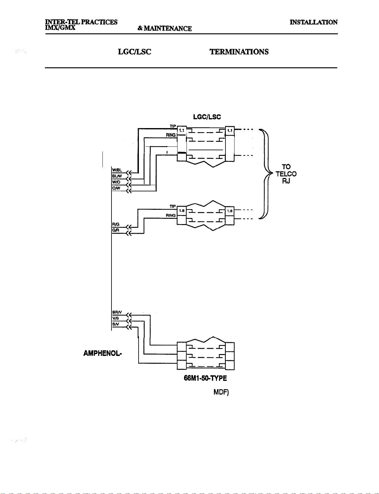
256 INSTALLATION
Issue 1, November 1994
FIGURE 3-5. LGC/LSC BLOCK CABLE TERMJNATIONS (METHOD A)
LOOP/GROUND
START CARD OR
LOOP START
CARD
TIP-
121r-12----
RING
----
r
TYPE
CONNECTOR
BLOCK
(PART OF
Page 3-13
Page 88
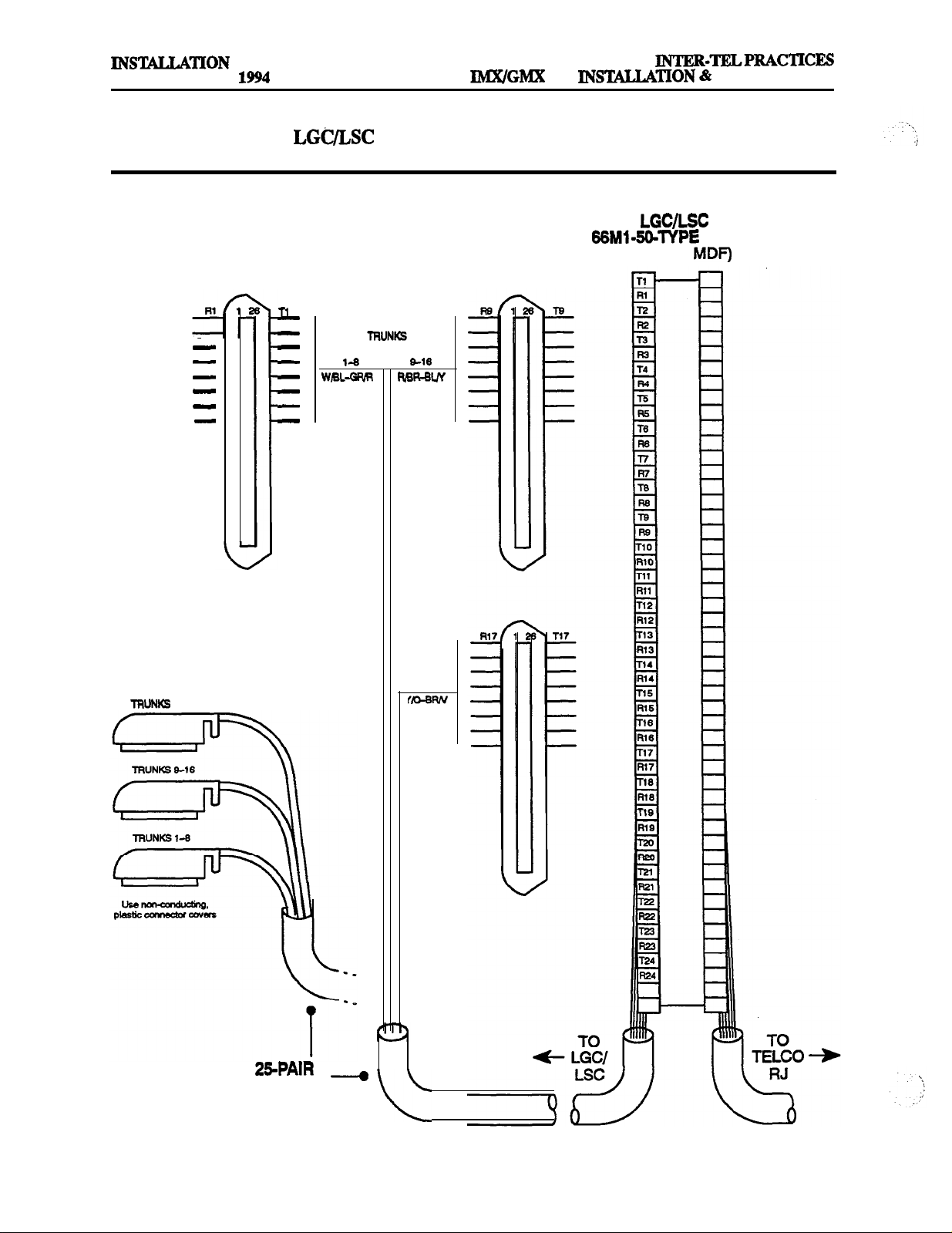
Issue 1, November
FIGURE 3-6.
256
MAINTENANCE
FEMALE AMPHENOL-TYPE CONNECTORS
17-24
(PART OF MDF)
CABLE TO
MDF
Page 3-14
Page 89

INTER-TELPRACTICES
256 INSTALLATION &
FIGURE 3-7. IDC BLOCK CABLE TERMINATIONS
Issue 1, November
IDC
INWARD
DIALING
CARD
RING
1.2 1
RING
.
.
. 1.11
1.1
--
1.2
--
--
--
--
--
--
--
TO
TELCO
RJ
1.8
1.1
TYPE
CONNECTOR
BLOCK
(PART OF MDF)
NOTE: The AC Enable terminations shown above are used only when installing single-lines sets and playback devices, not DID trunks. For information on their use, refer to the following pages.
Page 3-15
Page 90

Issue 1, November
256 INSTALLATION
INTER-TELPRACTICES
MAINTENANCE
FIGURE 3-8. EMC BLOCK CABLE TERMINATIONS
EMC
TO
TELCO
RJ
E&M
CARD
H
U
TO
TELCO
RJ
r
TYPE
CONNECTOR
NOTE: Depending on the area of the country and/or the specific type of E&M trunk ordered, one or more of
the cable pairs shown above may not always be needed. For each E&M trunk to be installed, terminate all
cable pairs provided by the telephone company, as shown in the
BLOCK
(PART OF MDF)
above.
Page 3-16
Page 91

INTER-TELPRACTICES
B.
The installation procedure
spans at the
tion used by the telephone company and how close it is
to the MDF. The
modular jacks or on RJ-type terminal blocks.
5.9 Follow one of the three
(A, B, or C) outlined on the following pages.
NOTE: The
dard RJ4gC jack provided on the
certain situations (e.g., when using an external
equipped with a
venient to use the card’s optional
instead. Refer to page
Method A
Jacks Near The MDF
256
CONNECTING Tl
is dependent on the type of termina-
spans may be terminated on RJ48C
span is typically connected to the stan-
connector), it may bc more con-
Tl Spans Terminated On RJ4SC
&
TO
termination methods
Card. However, in
for more information.
MDF
to connect
connector
INSTALLATION
Issue 1, November 1994
Mount one eight-conductor modular jack assem-
bly next to each telephone company RJ48C jack.
For each modular jack assembly mounted in step
1, also mount a corresponding
modular jack assembly on the MDF backboard.
To connect the modular jack assemblies
(3)
mounted in steps 1 and 2:
a. Run
modular jack assemblies.
NOTE: If the telephone company termination is more than 2000 feet from the MDF,
special
for cable specifications). For shorter distances, two lengths of standard two-pair voice-frequency cable (one cable for transmit
stead.
cable between the
cable
and one cable for receive) may be used in-
be used (see page
5.10
Install
the MDF as outlined in below.
Plug one end of a four-pair, non-reversing
(straight through), mod-to-mod line cord into
each telephone company RJ48C jack. The other
end of each line cord will Zater be plugged into
the
NOTE: Make sure the connectors on the ends of
each line cord are properly attached. If any of the
wires are cracked or broken,
problems can occur.
Method B
Jacks Away
to Figure 3-9 on the next page for a diagram of the complete layout.
spans terminated on RJ4gC jacks near
jack on the corresponding
Spans Terminated On RJSSC
The
spans terminated on RJ48C jacks away
Card.
transmission
b.
At the telephone company termination, plug one
end of a four-pair, non-reversing (straight
through), mod-to-mod line cord into each RJ4gC
jack and plug the other end into the correspond-
ing modular jack assembly next to it.
At the MDF backboard, plug one end of a four-
pair, non-reversing (straight through), mod-to-
mod line cord into each modular jack assembly.
The other end of each line cord will
plugged into the
Card.
NOTE: Make sure the connectors on the ends of
each line cord are
wires are cracked or broken,
problems can occur.
each end of the cable onto their respec-
tivemodular jack assemblies. Refer to Figure
3-10 on the next page for a diagram of the
wiring.
be
jack on the correspondingT1
attached. Ifauy of the
transmission
Page
Page 92
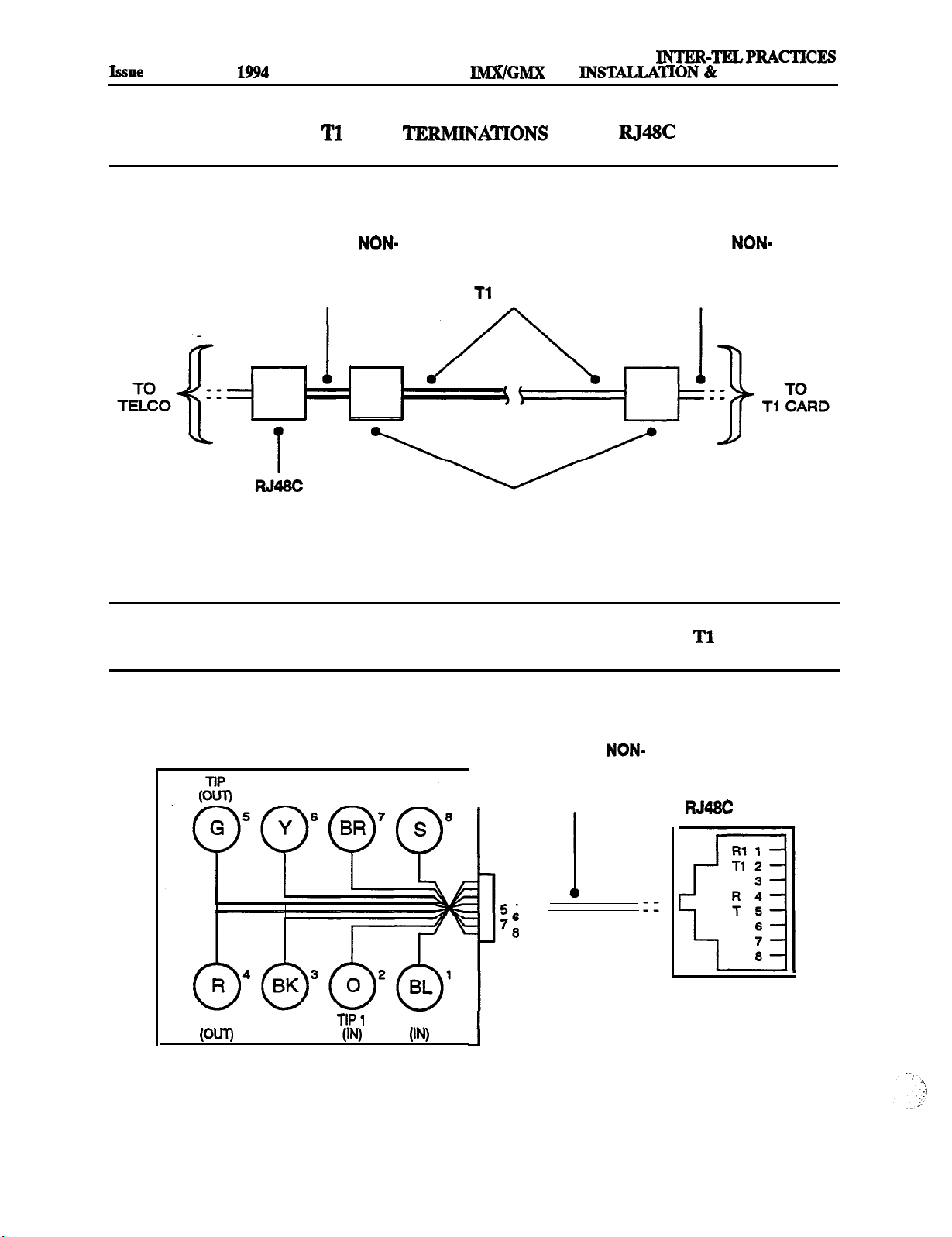
INSTALLATION
1, November 1994
FIGURE 3-9,
SPAN
256 INS’ICAUATON & MAINTENANCE
FROM
JACKS
.
FOUR-PAIR, NON-
REVERSING,
MOD-TO-MOD
LINE CORD
JACK
CABLE
EIGHT-CONDUCTOR
MODULAR JACK ASSEMBLIES
FOUR-PAIR, NON-
REVERSING,
MOD-TO-MOD
LINE CORD
FIGURE 3-10. MODULAR JACK ASSEMBLY WIRING FOR
SPANS
MODULAR JACK ASSEMBLY FOUR-PAIR, NON-
REVERSING,
MOD-TO-MOD
LINE CORD
‘2
34 --
--
RING
1
RING 1
NOTE: OUT = transmit to network, IN = receive from network
Page 3-18
Tl CARD
JACK
Page 93
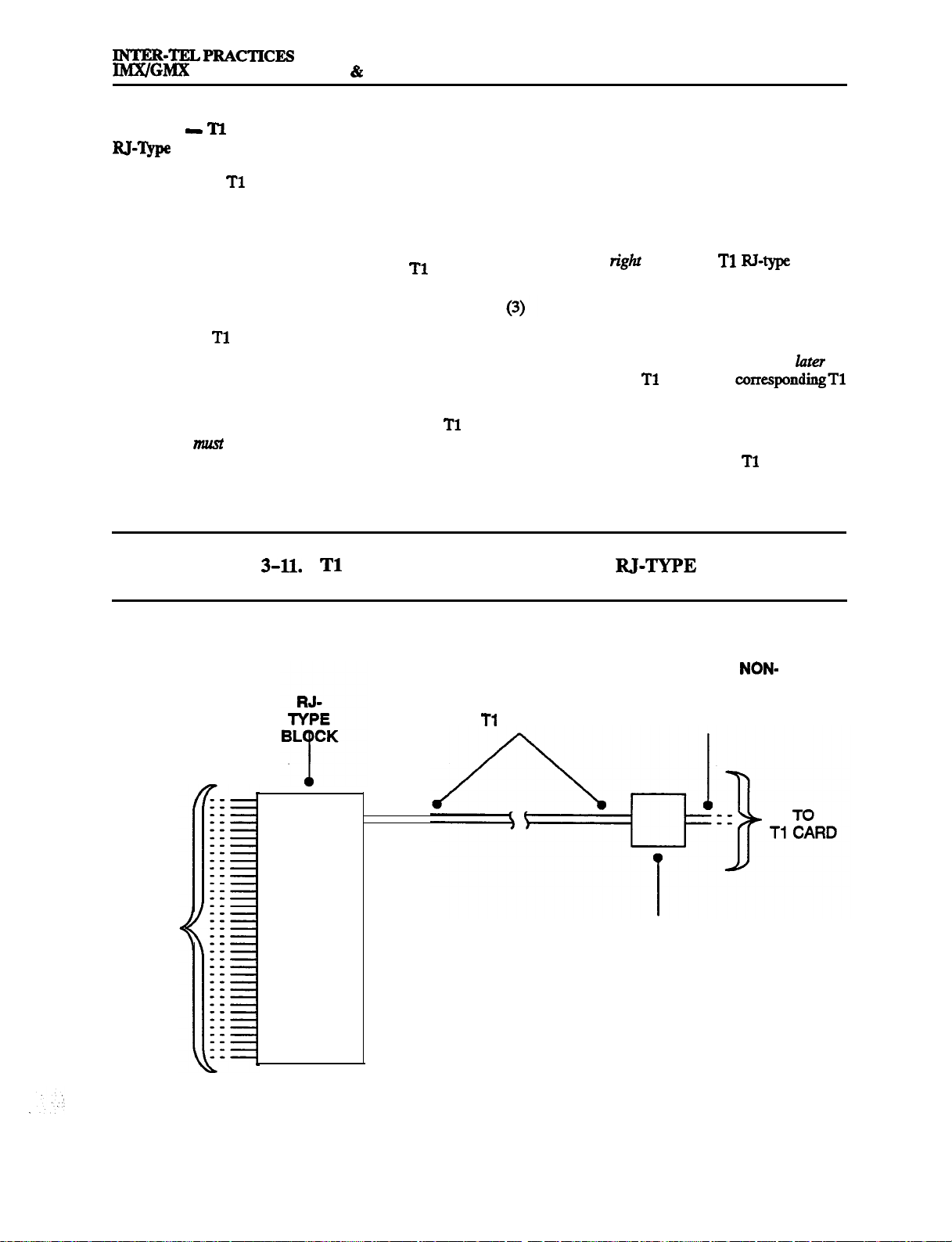
256 INSTALLATION
MAINTENANCE
INSTALLATION
Issue 1, November 1994
Method C
5.12 Install the
Block
Spans Terminated On An
spans as outlined in the following
steps. Refer to Figure 3-11 below for a diagram of the
complete layout.
(1) On the MDF backboard, mount one eight-con-
ductor modular jack assembly for each
span
termination on the telephone company RJ-type
block(s).
(2) Connect
cable between the telephone compa-
ny terminations and the corresponding modular
jack assemblies as follows:
NOTE: If the telephone company termination is
more than 2000 feet from the MDF, special
cable must be used (see page 2-20 for cable specifications). For shorter distances, two lengths of
standard two-pair voice-frequency cable (one
FIGURE
SPAN TERMINATIONS FROM R&TYPE BLOCKS
cable for transmit
and one
cable for receive) may
be used instead.
a.
Terminate one end of a six-pair cable on each
modular jack assembly. Refer to Figure 3-10
on the previous page.
b.
Terminate the other end of the six-pair cable
on the
side of the
R&type terminal
block.
Plug one end of a four-pair, non-reversing
(straight through), mod-to-mod line cord into
each modular jack assembly (mounted in step 1).
The other end of each line cord will
plugged into the
jack on the correspondingT1
be
Card.
NOTE: Make sure the connectors on the ends of
each line cord are properly attached. If any of the
wires are cracked or broken,
transmission
problems can occur.
TO
TELCO
CABLE
FOUR-PAIR, NON-
REVERSING,
MOD-TO-MOD
LINE CORD
EIGHT-CONDUCTOR
MODULAR JACK ASSEMBLY
Page 3-19
Page 94

Issue 1, November
256
MAINTENANCE
Using The Optional
The
Jack
the preceding pages show the
to the RJ48C jack on the
Connector In Place Of
span being connected
Card. However, in certain
situations (e.g., when using an external CSU equipped
with a DB15 connector), the installer may wish to use
the card’s optional
The pin functions of the
5.14
connector instead.
Card
connec-
tor (U-pin subminiature “D” female connector) are as
follows:
FIGURE 3-12.
MALE DB15 CONNECTOR
TO
SPAN TOT1 CARD
CARD’S OPTIONAL
To connect the
5.15
a DB15 connector coming
connector on the
the
span, a flat,
Card to
twisted-pair ribbon cable with a maximum
capacitance of 16pF/ft. may be used for distances of up
to 50 feet, as shown in the figure below. For distances
longer than 50 feet, use the special high-speed data
cable described in paragraph 3.91 on page
CONNECTOR
MALE DB15 CONNECTOR
Ring (Out) 9
1
10
lip 1 (In) 3
Ring 1 (In) 11
12
13
14
-15
2
4
6
7
NOTE: OUT = transmit to network, IN = receive from network
9 Ring (Out)
2
10
3
1 (in)
11 Ring 1 (in)
4
12
5
13
6
14
7
15
Page 3-20
Page 95

256
MAINTENANCE
Issue 1, November 1994
C.
CABLES TO THE
MDF
5.16
Each type of station instrument is comtected to a
specific station card. Digital keysets are connected to
I
Attendant Computer Consoles are comtected to KSCs or
Analog
analog
Units, and
KSC-Ds. Single-line sets and playback devices are connected to SLCs and/or IDCs.
Resides single-line sets, playback devices, and
off-premises extensions, IDCa can also be used to install
DID trunks. Any combination using the eight circuits on
the card is Possible. Refer to pages 3-11 to 3-15 for DID
trunk installation instructions.
5.17 After the
station cables are run, connect them and
the 25-pair cables to the station blocks on the MDF as
follows:
Ensure that both ends of each station cable are labeled with the circuit number of the associated
station instrument.
Terminate each station cable on the
side of
the corresponding station block. Refer to Figures
3-13 through 3-19 on the following pages for
station cable terminations.
NOTE: For simplicity, Figures
and
3-18 show digital keysets, single-line sets, and
playback devices being installed using one-pair
cable and four-conductor modular jacks. Of
course, if three-pair cable and six-conductor
modular jacks are used instead (as is
mended), extra terminal blocks and the use of
cross-connect wiring techniques are required.
Using enough
cable to run from each
block to each station card in the equipment cabinet, make the termination cables. Attach a
end of each cable. Label each
and
cable end with the appropriate slot number (for
example, SLOT-2). These
will be at-
tached to the station cards after the circuit cards
are installed.
Using standard electrical tape, tape two ferrite
split beads around each 25-pair cable just below
the amphenol-type connector (as shown in Figure 3-12).
Ferrite beads must be installed to meet
Part 15 of FCC regulations. Refer to REPLACEMENT
for the part number.
Terminate the other end of each 25-pair cable on
the
side of the corresponding station block.
NOTE:
an IDC can be enabled for
necessary, any of the eight circuits on
AC ringing to be used
with off-premises extensions or on-premises
AC-ringing equipment. To do this, each circuit
can be strapped directly at the IDC terminal
block (as shown in Figure 3-18 on page 3-27) or
on the card itself (as described on page 3-51).
DO NOT
attach bridging clips until the loop resistance tests have been performed (as described
on page 3-29).
Page 3-21
Page 96

Issue 1, November 1994
INTER-TELPRACTICES
&MAINTENANCE
FIGURE 3-13.
L
KSC BLOCK CABLE TERMINATIONS FOR
DKSC
RING
RING
RING
1 l-1.1.1
--
--
, . .
MODULAR
JACK
ASSEMBLY
TO DIGITAL
TO DIGITAL
DIGITAL
CARD
TYPE
CONNECTOR
NOTE: For simplicity, this figure shows keysets being installed using one-pair cable and four-conductor
modular jacks. Of course, if two-pair cable or three-pair cable is used instead, extra terminal blocks and the
use of cross-connect wiring techniques are required. Note that tip and ring are
terminals (black and yellow) on the modular jack.
BLOCK
(PART OF
connected
to the
of
Page 3-22
Page 97
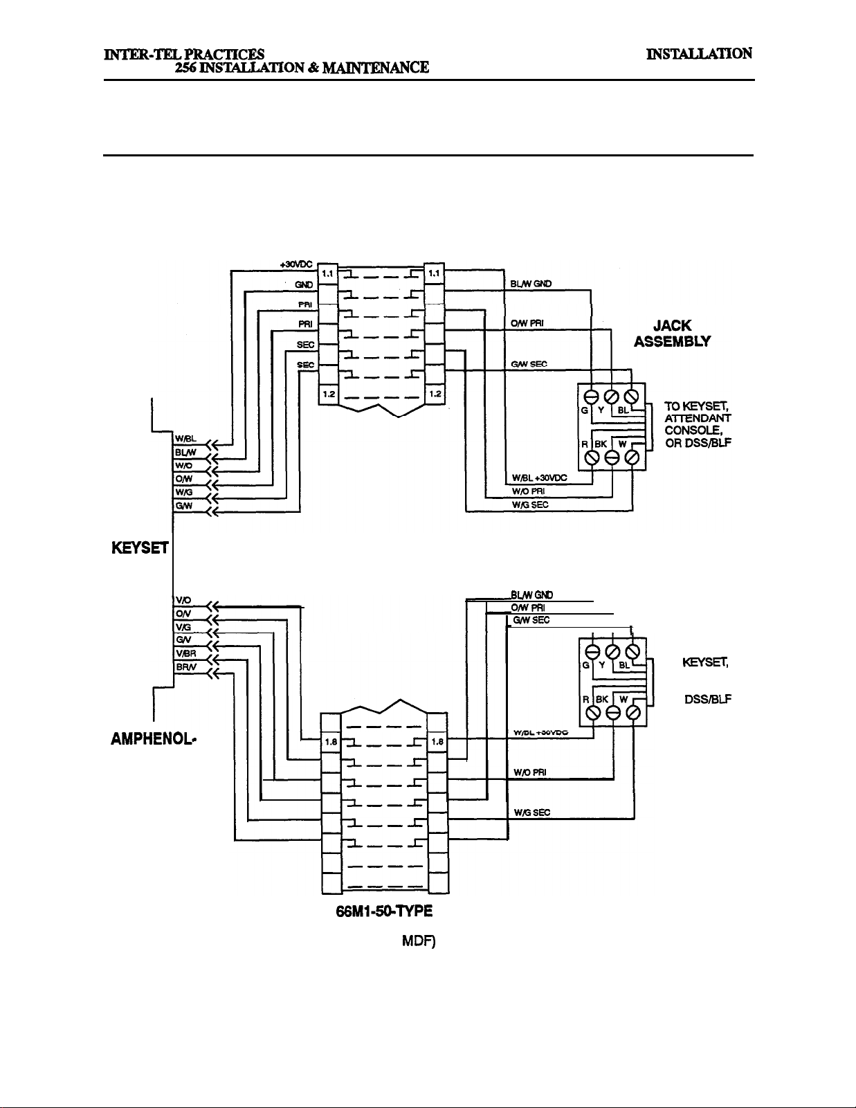
IMX’GMX
Issue 1, November 1994
FIGURE 3-14. ANALOG KSC BLOCK CABLE TERMINATIONS
KSC
MODULAR
CARD
TYPE
CONNECTOR
BLOCK
(PART OF
MODULAR
I
I
I
JACK
ASSEMBLY
TO KEYSET,
ATTENDANT
CONSOLE,
OR DSSBLF
Page 3-23
Page 98

IN-TION
Issue 1, November
FIGURE 3-15. INSTALLING S-LINE IMX AIM
MDF
A
TWO TO A CIRCUIT
CIRCUIT 1 .lA
CIRCUIT 1.1A
!
C
MDF
BLOCK
CIRCUIT
KSC-D
CIRCUIT
NOTE: This illustration shows three common methods for installing two 8-line IMX
KSC-D circuit. For a detailed wiring diagram of method A, refer to the following-page.
Page 3-24
keysets on a single
Page 99

INSTALLATION
MAINTENANCE
Issue 1, November 1994
FIGURE 3-16. KSC-D BLOCK CABLE TERMINATIONS FOR &LINE IMX AIM
INSTALLED TWO TO A CIRCUIT
MODULAR
CIRCUIT 1
CIRCUIT 1
KSGD
I
I
I
MODULAR
JACK
BLOCK
(PART OF
SEC
I
NOTE: This illustration details one common method for wiring two Mine IMX
KSC-D circuit. For a simple illustration of some alternative installation methods, refer to the previous page.
keysets to a single
CIRCUIT 1
I I
B
TO S-LINE
AIM KEYSET
Page 3-25
Page 100

INSTALLATION
Issue 1, November
256
INTER-TELPRACTICES
MAINTENANCE
SINGLE-
LINE
CARD
FIGURE 3-17.
SLC BLOCK CABLE TERMINATIONS
MODULAR
JACK
ASSEMBLY
Y
BK
TO SINGLELINE SET OR
PLAYBACK
DEVICE
MODULAR
JACK
TO SINGLE-
LINE SET OR
DEVICE
TYPE
CONNECTOR
BLOCK
(PART OF MDF)
NOTE: For simplicity, this figure shows single-line sets and playback devices being installed using one-pair
cable and four-conductor modular jacks. Of course, if three-pair cable and six-conductor modular jacks are
used instead (as is recommended), extra terminal blocks and the use of cross-connect wiring techniques are
required.
Page 3-26
 Loading...