

Intertek TASMAN EP & HP, TASMAN EP, TASMAN HP Installation And Operating Instructions Manual
Page 1
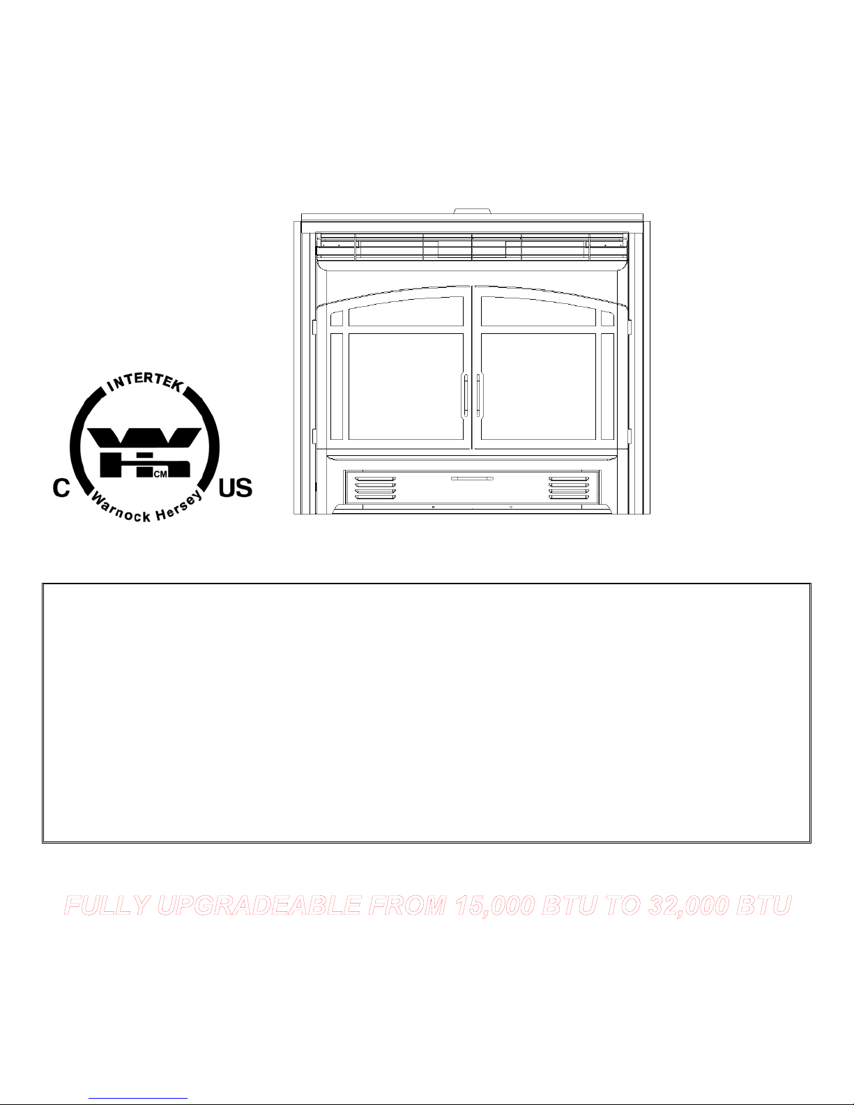
TASMAN EP & HP
Natural Gas & Propane
Zero Clearance Direct Vent Gas Fireplace
Installation and Operating Instructions
Optional Screen Door shown
WARNING: If the information in this manual is not followed exactly, a fire or explosion may result causing
property damage, personal injury, or loss of life.
For your safety
Do not store or use gasoline or other flammable vapors and liquids in the vicinity of this or any other appliance.
What to do if you smell gas
Do not try to light any appliance.
Do not touch any electrical switch; do not use any phone in your building.
Immediately call your gas supplier from a neighbor’s phone. Follow the gas supplier’s instruction s.
If you cannot reach your gas supplier, call the fire department.
Installation and service must be performed by a qualified installer, service agency or the gas supplier.
Please read this manual before installing or using this appliance. Retain this manual for future reference.
See inside manual (page 59) for upgrade information
Page 1 of 80
Page 2

Table of Contents
1.0 INTRODUCTION.....................................................................................................................
1.1 Specifications, Appliance Dimensions & Installation Codes................................3 & 4
1.2 Features .....................................................................................................................5
1.3 Intended Use..............................................................................................................5
1.4 General Safety............................................................................................................6
2.0 OPERATION...........................................................................................................................
2.1 Lighting Instructions ............................................................................................ 7 & 8
2.2 Heat Output Adjustment ............................................................................................9
2.3 Fan Operation ............................................................................................................9
3.0 INSTALLATION .....................................................................................................................
3.1 Installation & Safety Notes ......................................................................................10
3.2 Unpacking ...............................................................................................................10
3.3 Installation ...............................................................................................................10
3.3.1 Minimum Clearances ....................................................................................... 10 - 12
3.3.2 Gas Line Installation ................................................................................................13
3.3.3 Thermostat or Wall Switch & Wiring Connections ........................................... 13 & 14
3.3.4 Direct Vent Information .............................................................................. …...15 - 36
3.3.5 Firebox Component Installation........................................................................ 37 - 47
3.3.6 Door Installation .............................................................................................. 48 & 49
3.3.7 Initial Firing & Manifold Pressure..............................................................................50
3.3.8 Primary Air Adjustment ............................................................................................51
3.3.9 Altitude Adjustment ..................................................................................................52
3.3.10 Field Assembled Parts ....................................................................................53 – 58
4.0 MAINTENANCE .....................................................................................................................
4.1 Maintenance Safety .................................................................................................59
4.2 Recommended Service ...........................................................................................59
4.3 Glass Cleaning ........................................................................................................59
4.4 Burner & Pilot Cleaning ...........................................................................................60
4.5 Optional Fan Installation ..........................................................................................60
4.6 Valve & Pilot Replacement .....................................................................................60
5.0 TROUBLE SHOOTING ……………………………………………………………………. 61 & 62
6.0 REPLACEMENT PARTS …………………………………………………………………. 63 & 64
7.0 WARRANTY …………………….…………………………………………………………. 65 & 66
8.0 LABEL INFORMATION (E-UNIT)………………………………………………………… 67 & 68
APPENDIX A (H-UNIT UPGRADE)…….…………………………………………………………. 69 – 74
APPENDIX B (CONVERSION KIT) …….………………………………………………………….75 – 77
APPENDIX C (INTERMITTENT PILOT & VALVE KIT)…………………………………………..78 - 80
Inca Metal Cutting
Unit 100 Sales and office #115 shipping
11091 Bridgeport Rd
Richmond BC
V6X-1T3
Page 2 of 80
Page 3
1.0 INTRODUCTION
1.1 SPECIFICATIONS
TABLE 1
ITEM NATURAL GAS (NG) PROPANE (LPG)
INPUT: Hi 18,000 Btu/hr (5.27 kW) 15,000 Btu/hr (4.39 kW)
INPUT: Lo 12,500 Btu/hr (3.66 kW) 12,500 Btu/hr (3.66 kW)
MANIFOLD PRESSURE: Hi 3.5” w.c. (0.87 kPa) 10” w.c. (2.49 kPa)
MANIFOLD PRESSURE: Lo 1.7” w.c. (0.42 kPa) 6.4” w.c. (1.57 kPa)
GAS INLET SUPPLY
PRESSURE:
Maximum: 13.5” w.c. (3.4 kPa) Maximum: 14” w.c. (3.49 kPa)
ORIFICE SIZE: @ 0-4500’ # 48 DMS # 57 DMS
CONTROL VALVE TYPE: Honeywell , SIT 820 Nova,
VENTING 2-ply aluminum vent,
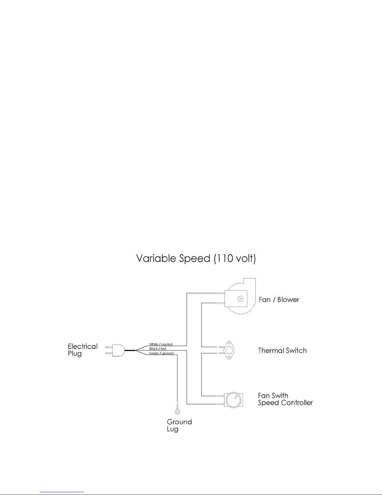
FAN * Optional * Variable Speed (120 Volt) Variable Speed (120 Volt)
Minimum: 5.0” w.c. (1.2 kPa) Minimum: 12” w.c. (2.99 kPa)
Honeywell , SIT 820 Nova,
Robertshaw-Grayson or
Skytech AF-4000
Simpson Dura-Vent, Selkirk or
Security
Robertshaw-Grayson or
Skytech AF-4000
2-ply aluminum vent,
Simpson Dura-Vent, Selkirk or
Security
Page 3 of 80
Page 4
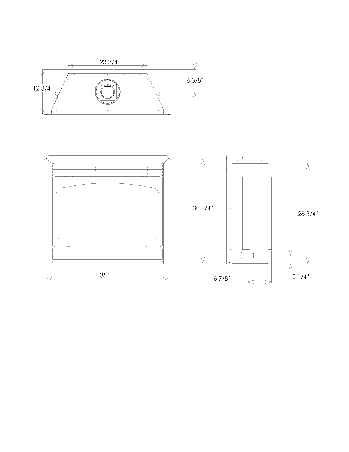
APPLIANCE DIMENSIONS
Figure 1
INSTALLATION CODES
Installation must conform to local codes. In the absence of local codes, installation must conform to
the National Fuel Gas Code, ANSI Z233.1, or the current CAN/ CGA B149.1 Installation Codes. The
unit, when installed, must be electrically grounded in accordance with local codes or, in the absence
of local codes, with the National Electric Code ANSI/NFPA No. 70 or with the current CSA C22.1
Canadian Electrical Code. In the state of Massachusetts, this product can only be installed by a
licensed plumber or a licensed gas fitter. Failure to comply will void the warranty.
Page 4 of 80
Page 5

1.2 FEATURES
Ignition system:
Standing pilot ignition system with thermopile and thermocouple flame detection and piezo igniter.
Gas control:
Gas control valve type:
Automatic millivolt powered combination gas control valve with variable flame control for
convenience and on/off switch. Optional digital remote on/off wall switch and/or optional wall
thermostat (note: thermostats are not allowed in the United States). The gas valve does not
require electricity from an external source.
Fan control * Optional *
Variable speed control:
For units equipped with a fan control, the knob controls the fan speed, turning the knob
counter-clockwise turns it to the “Off” position.
1.3 INTENDED USE
This appliance is intended to be used as a zero clearance fireplace. This unit is certified for
installation in a bedroom or a bed sitting room where the maximum input is within 50 cubic feet per
1000 Btu/hr, (i.e. 900 cubic feet for E unit & 1600 cubic feet for H unit). In Canada all bedroom
installations require the use of wall thermostats (note: thermostats are not allowed in the United
States).
Page 5 of 80
Page 6

1.4 GENERAL SAFETY
Maintain adequate clearances around air openings into the combustion chamber.
Maintain adequate accessibility clearances for servicing and proper operation.
This appliance shall not be connected to chimney flue serving a separate solid-fuel burning
appliance.
The appliance area must be kept clear and free from combustible materials, gasoline and other
flammable liquids and vapors.
The flow of combustion and ventilation air shall not be obstructed.
The combustion air supply shall be in the same pressure zone as the drafthood relief opening
on an appliance equipped with a drafthood or as the vent outlet on an appliance not equipped
with a drafthood.
Do not use this appliance if any part has been under water. Immediately call a qualified
service technician to inspect the appliance and to replace any part of the control system and
any gas control which has been under water.
Due to high temperatures, the appliance should be located out of traffic and away from furniture
and draperies.
Children and adults should be alerted to the hazards of high surface temperature and should stay
away to avoid burns or clothing ignition.
Young children should be carefully supervised when they are in the same room as the appliance.
Clothing or other flammable material should not be placed on or near the appliance.
Any safety screen or guard removed for servicing an appliance must be replaced prior to operating
the appliance.
Installation and repair should be done by a qualified service person. The appliance should be
inspected before use and at least annually by a professional service person. More frequent
cleaning may be required due to excessive lint from carpeting, bedding material, et cetera. It is
imperative that control compartments, burners and circulating air passageways of the appliance be
kept clean.
Page 6 of 80
Page 7

2.0 OPERATION
2.1 LIGHTING INSTRUCTIONS
FOR YOUR SAFETY, READ BEFORE LIGHTING
WARNING: If you do not follow these instructions exactly, a fire or explosion may result
causing property damage, personal injury or loss of life.
A. This appliance has a pilot which must be lighted by hand. When lighting the pilot, follow these instructions exactly.
B. BEFORE LIGHTING smell all around the appliance area for gas. Be sure to smell next to the floor because some gas is heavier than air and will
settle on the floor.
WHAT TO DO IF YOU SMELL GAS
Do not try to light any appliance.
Do not touch any electric switch; do not use any phone in your building.
Immediately call your gas supplier from a neighbour’s phone. Follow the gas supplier’s instructions.
If you cannot reach your gas supplier, call the fire department.
C. Use only your hand to push in or turn the gas control knob. Never use tools. If the knob will not push in or turn by hand, don’t try to repair it, call a
qualified service technician. Force or attempted repair may result in a fire or explosion.
D. Do not use this appliance if any part has been under water. Immediately call a qualified service technician to inspect the appliance and to replace
any part of the control system and any gas control which has been under water.
LIGHTING INSTRUCTIONS
1. STOP! Read the safety information above on this label.
2. Set the thermostat to the lowest setting.
3. Turn off all electric power to the appliance.
4. Controls are accessed by opening the bottom louver.
5. Push in gas control knob slightly and turn clockwise to “OFF”.
6. Wait five (5) minutes to clear out any gas. Then smell for gas, including near the floor. If you smell gas, STOP! Follow “B” in the safety
information above on this label. If you don’t smell gas, go to the next step.
7. Turn control knob counterclockwise pilot position.
8. Depress control knob and push in piezo igniter button. Once pilot ignites continue to hold the control knob in for one (1) minute after the pilot is lit.
Release knob and it will pop back up. Pilot should remain lit. If it goes out, repeat steps 4 – 7.
If knob does not pop up when released, stop and immediately call your service technician or gas supplier.
If the pilot will not stay lit after several attempts, turn the gas control knob to “OFF” and call your service technician or gas supplier.
9. Turn gas control knob counterclockwise to “ON”. Turn on all electric power to the appliance. Set thermostat to desired setting or turn appliance
switch to “ON” position then close bottom louver.
TO TURN GAS OFF TO APPLIANCE
1.Set thermostat to lowest setting.
2.Turn off all electric power to the appliance if service is to be performed.
3.Push in gas control knob slightly and turn clockwise to “OFF”, do not force.
Note: The valve is equipped with a safety lockout, once in the “ OF F” posi tion you must wait until the thermopile has cooled before attempting
to light the pilot (approximately 3 minutes).
Page 7 of 80
Page 8
LIGHTING INSTRUCTIONS - for Intermittent Pilot
FOR YOUR SAFETY, READ BEFORE LIGHTING
WARNING: If you do not follow these instructions exactly, a fire or explosion may result causing property
damage, personal injury or loss of life.
A. This appliance is equipped with an ignition device which automatically lights the pilot. Do not try to light the pilot by hand.
B. BEFORE LIGHTING smell all around the appliance area for gas. Be sure to smell next to the floor because some gas is heavier than air and will
settle on the floor.
WHAT TO DO IF YOU SMELL GAS
Do not try to light any appliance.
Do not touch any electric switch; do not use any phone in your building.
Immediately call your gas supplier from a neighbour’s phone. Follow the gas supplier’s instructions.
If you cannot reach your gas supplier, call the fire department.
C. Use only your hand to push in or turn the gas control knob. Never use tools. If the knob will not push in or turn by hand, don’t try to repair it, call a
qualified service technician. Force or attempted repair may result in a fire or explosion.
D. Do not use this appliance if any part has been under water. Immediately call a qualified service technician to inspect the appliance and to replace
any part of the control system and any gas control which has been under water.
LIGHTING INSTRUCTIONS
1. STOP! Read the safety information above on this label.
2. Set the thermostat to the lowest setting.
3. Turn off all electric power to the appliance.
4. "ON / OFF" switch is accessed by opening the bottom louver.
5. Do not attempt to light the pilot by hand.
6. Wait five (5) minutes to clear out any gas. Then smell for gas, including near the floor. If you smell gas, STOP! Follow “B” in the safety
information above on this label. If you don’t smell gas, go to the next step.
7. Turn on all electric power to the appliance.
8. Set thermostat to desired setting (or switch to "ON" if not using a thermostat).
9. Close bottom louver.
10. If the appliance will not operate, follow the instructions "To Turn Off Gas To Appliance" and call your service technician or gas supplier.
TO TURN GAS OFF TO APPLIANCE
1.Set thermostat to lowest setting.
2.Turn on/off switch to off.
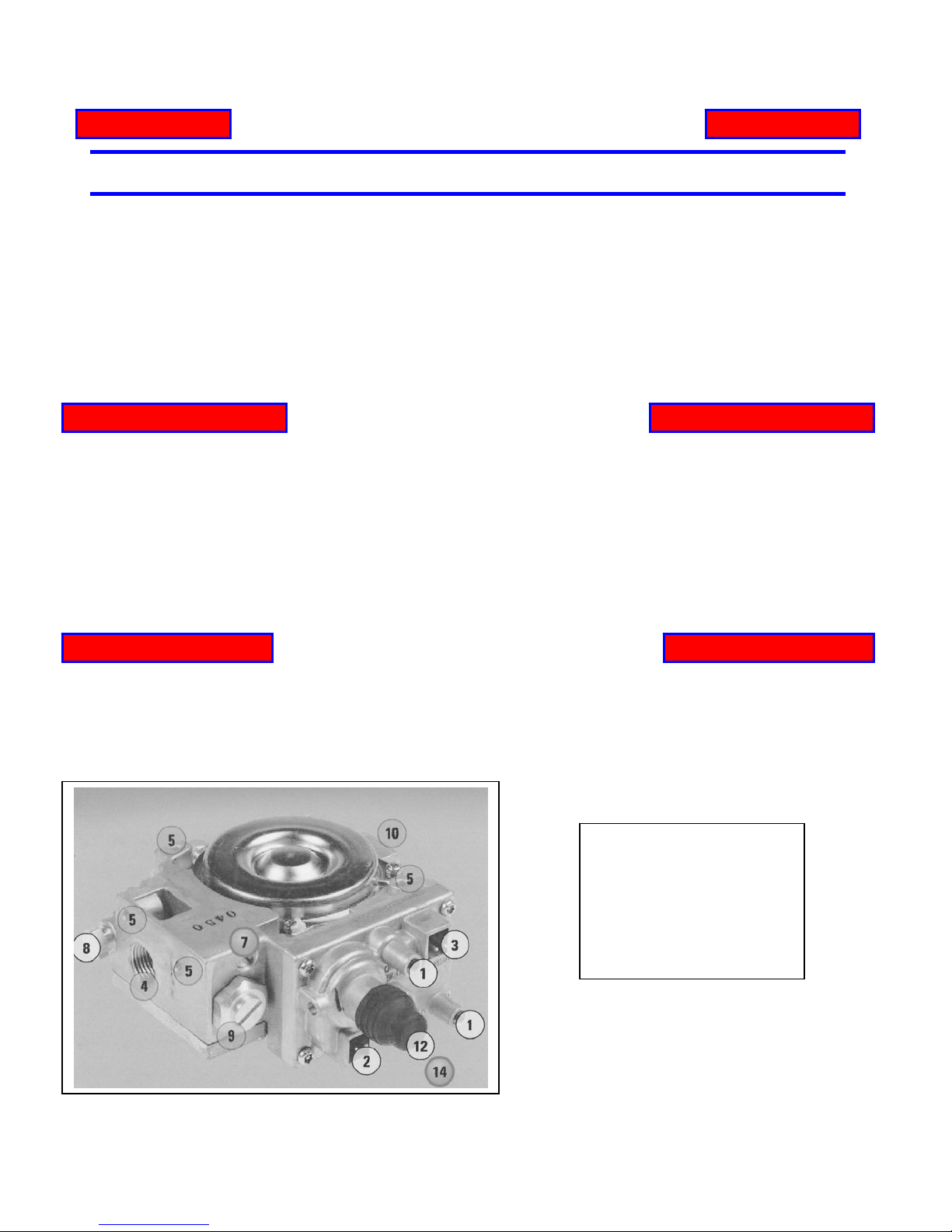
1. Pressure Taps
2. Main Valve Connection
3. Pilot Internal Solenoid Connection
4. Outlet Ports
5. Mounting Holes
7. Flow Control Screw
8. Pilot Connections
9. High/Low Connection
10. Inlet Ports
Page 8 of 80
Page 9
2.2 HEAT OUTPUT ADJUSTMENT
The valve supplied with the appliance has a HI/LO knob to control the heat output and flame height
(see valve diagram in Lighting Instructions, section 2.1).
2.3 FAN OPERATION
For units equipped with a fan control knob, the knob is located in the valve control compartment and
may be adjusted to the following settings:
OFF: Turn the control fully counter-clockwise until the switch operates.
Variable Speed Setting:
Turn the control to the desired setting. When the knob is turned fully clockwise the fan will set to
minimum speed.
Warning
Electrical Grounding Instructions
This appliance is equipped with a three prong (grounding) plug for your protection against shock
hazard and should be plugged directly into a properly grounded three prong receptacle. Do not cut or
remove the grounding prong from this plug.
Figure 2
Page 9 of 80
Page 10
3.0 INSTALLATION
3.1 INSTALLATION & SAFETY NOTES
Read all instructions before starting installation and follow them carefully during installation to ensure
maximum benefit and safety. Failure to follow these instructions will void your warranty and may
present a fire hazard. See the warranty at the back of this manual for disclaimers regarding improper
installation. This direct vent fireplace and it’s components are tested and safe when installed in
accordance with this installation manual.
WARNING: Do not connect 120 VAC to the gas control valve or it’s wiring, as this
will damage the valve.
3.2 UNPACKING
Please check the appliance carefully for any damaged or missing components (specifically check the
glass condition). Report any problems to your dealer within 30 days of purchase.
3.3 INSTALLATION
For satisfactory results it is necessary to plan certain aspects of the installation prior to the
appliance’s final positioning. These include the vent system, the gas piping, and the fans wiring.
Combustible surfaces such as the hearth, mantle, and facing must also be planned for. Be sure to
leave adequate clearance for servicing and proper operation.
NOTE: All Installations Require Venting.
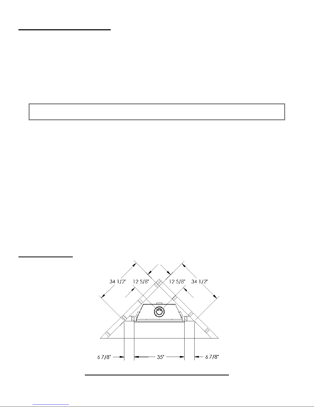
3.3.1 MINIMUM CLEARANCES
Corner Installation
Page 10 of 80
Page 11
3.3.1 MINIMUM CLEARANCES (continued)
Figure 3
Page 11 of 80
Page 12
3.3.1 MINIMUM CLEARANCES (continued)
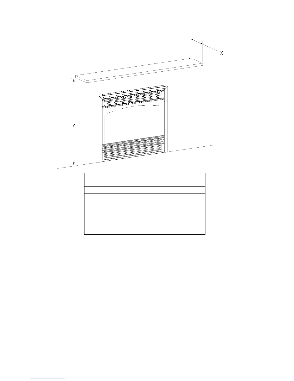
Mantle Height
Mantle Depth (X)
from Floor (Y)
40" 10"
39" 9"
38" 8"
37" 7"
36" 6"
34" 5"
33" 4"
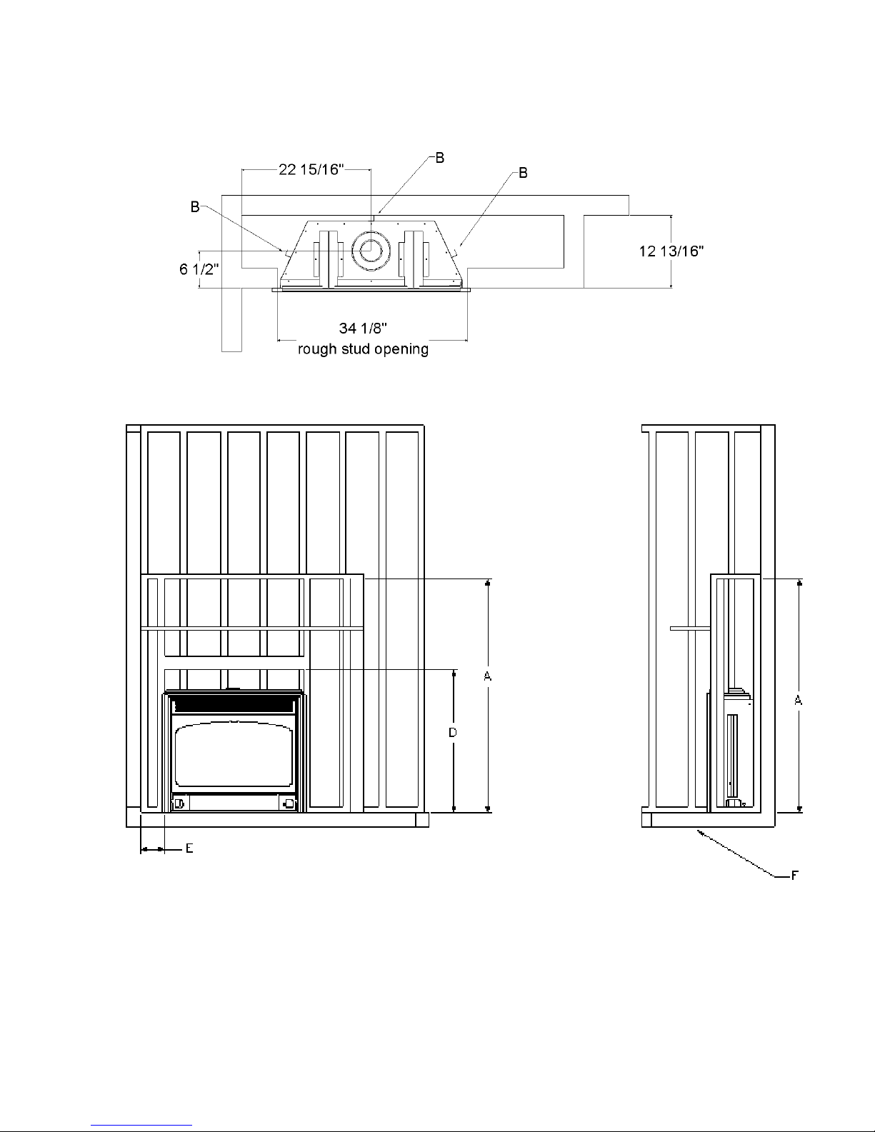
Minimum Clearances to Combustibles
A – Internal Ceiling 48” (1219 mm) from floor
B– Back & Sidewalls 0" (0 mm) with 1” (25 mm) Standoffs installed
Mantle (see chart)
D --Internal Framing 34-7/8” (886 mm) from floor to bottom edge of framing
E --Unit Trim to sidewall 6” (152 mm)
F - Floor 0” (0 mm)
Note: Check local codes for floor requirements.
This fireplace is suitable for installation on a combustible surface.
“Clearances are in accordance with local installation codes and the requirements of the gas supplier.”
**The mantel placement chart on the previous page illustrates the allowable mantel sizes and
placements. The 1” incremental grid can be used to determine the allowable mantel size based on
the elevation above the units upper trim.
When using paint or lacquer to finish the mantel, such paint or lacquer must be heat resistant
(up to 250º F) to prevent discolorations.
Page 12 of 80
Page 13

3.3.2 GAS LINE INSTALLATION
Install supply line using any piping approved for your installation meeting CAN/CGA 6.10, AA 3,
ANSI Z21.24 or Z21.45. A qualified gas fitter should install the gas line in accordance with all
local building codes. If codes permit, coiled copper tubing may be used for gas supply.
Pressure taps are provided on the gas control fo r test gauge connections to measure the manifold
and inlet pressures (see Lighting Instructions).
This appliance must be isolated from the gas supply piping system by closing its individual manual
shut off valve during any pressure testing of the gas supply piping system at test pressures equal
to or less than 1/2 psig (3.45 kPa).
The appliance and its individual shut off valve must be disconnected from the gas supply piping
system during any pressure testing of the system at test pressures in excess of 1/2 psig (3.45
kPa).
Install the gas line as follows:
The appliance shall be installed with a manual shut off ball valve and additional pressure
regulator to bring line pressure down to 14” w.c..
Upon initial firing check manifold pressure at pressure tap located on the front control panel
(see Lighting Instructions in section 2.1).
WARNING: Do not use an open flame to test for gas leaks.
3.3.3 THERMOSTAT, WALL SWITCH OR DIGITAL ON/OFF REMOTE INSTALLATION
The burner control knob is located in the control compartment at the bottom of the unit. For your
convenience, the unit can also be operated by a thermostat, a digital on/off remote or a wall switch
control. Millivolt thermostats are available from any authorized Inca Metal Cutting dealer. Bedroom
installations require the use of a wall thermostat. Note: Thermostats are not allowed in the United
States.
NOTE: The thermostat, digital on/off remote or wall switch MUST be rated for
millivolt use. Minimize splicing in all millivolt wiring & crimp all unavoidable splices.
Thermostat, Digital On/Off Remote or Wall Switch Installation
Mount the thermostat, digital on/off remote or wall switch in the desired location and run “two
conductor thermostat wire” to the unit’s lower right hand corner, close to the gas supply line.
1. Purchase “two conductor thermostat wire”, which is not provided, at any local supplier. The
gauge of thermostat wire will determine the maximum wire length and distance at which to locate
the thermostat, digital on/off remote or wall switch. See Table 1 and the information packaged
with thermostat. Be aware that as the length of wire increases, the probability of adequate
operating voltage decreases.
Page 13 of 80
Page 14
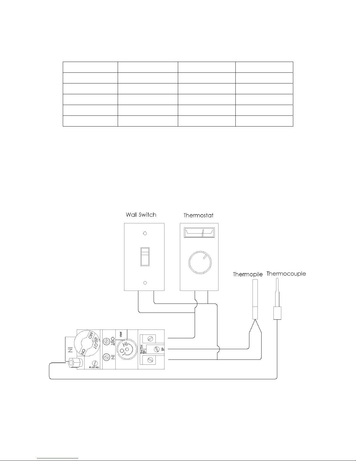
TABLE 1 THERMOSTAT WIRE INFORMATION
WIRE SIZE MAX. WIRE LENGTH
AWG mm ft. m
22 0.6 10 3.0
20 0.8 25 7.6
18 1.0 40 12.2
16 1.3 64 19.5
14 1.6 100 30.5
2) After the unit is installed and the gas line hooked up, crimp a fork connector to each wire and
attach them to the TH/TP and TH screws located on the valve.
3) Check tests can be performed on the valve by using the trouble-shooting guide, Section 5.0.
4) This switch may be connected in parallel with a thermostat, digital on/off remote or wall switch
(see Figure 4).
Figure 4
Page 14 of 80
Page 15
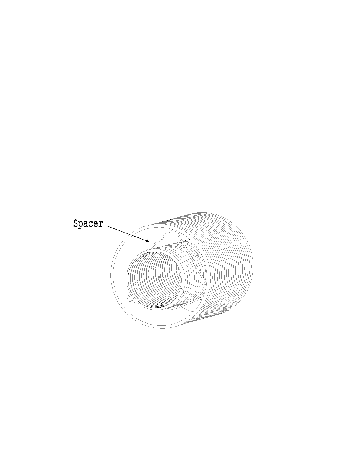
3.3.4 Direct Vent Information
The unit must be connected to listed 2-ply aluminium venting, 4” flex vent on the exhaust side and
listed 7” flex vent on the air intake side or can be used with Security Venting or Simpson Dura-Vent 4”
x 6-5/8” with the use of Simpson Dura-Vent adapters part #’s 0924N3 & P574. Install the vent
components according to the manufacturer's instructions being sure to use spacers (see Figure 5)
every 5’ to ensure correct spacing is maintained between air intake and exhaust. Slope horizontal
pipe at least 1/4" (6 mm) rise per foot of horizontal run. Allow 1" (25 mm) clearance to the vent.
Refer to the graph for allowable vent configurations. Be sure to ensure that termination area allows
enough room for adequate combustion and ventilation air and that the flow of combustion and
ventilation air is not obstructed.
Note: If at any time the vent-air intake piping is dismantled, use the vent manufacturer’s
instructions and the sealing instructions for reassembly.
Figure 5
Page 15 of 80
Page 16

3.3.4 Direct Vent Information (continued)
Simpson Dura-Vent
The minimum vent system for horizontal termination must consist of:
Simpson Dura-Vent adapter Part # 0924N3 directly on top of unit
90 degree elbow
12" (305 mm) length horizontally
Wall thimble part #IMC1082A
Horizontal termination cap 0984
The maximum horizontal vent system consists of:
Simpson Dura-Vent adapter Part # 0924N3 directly on top of unit
40' (12192 mm) vertical length directly on top of the stove
90 degree elbow
15' (4572 mm) maximum horizontal length
Wall thimble part# IMC1082A
Horizontal termination cap 0984
The maximum vertical system consists of:
Simpson Dura-Vent adapter Part # 0924N3 directly on top of unit
Up to 40' (12192 mm) of vertical length
Fire stop
Flashing
Collar
Termination cap part # 0991
Security Venting
The minimum vent system for horizontal termination must consist of:
Simpson Dura-Vent adapter Part # 0924N3 directly on top of unit
90 degree elbow
12" (305 mm) length horizontally
Wall thimble part #IMC1082A
Horizontal termination cap SV4CHC
The maximum horizontal vent system consists of:
Simpson Dura-Vent adapter Part # 0924N3 directly on top of unit
40' (12192 mm) vertical length directly on top of the stove
90 degree elbow
15' (4572 mm) maximum horizontal length
Wall thimble part# IMC1082A
Horizontal termination cap SV4CHC
The maximum vertical system consists of:
Simpson Dura-Vent adapter Part # 0924N3 directly on top of unit
Up to 40' (12192 mm) of vertical length
Fire stop
Flashing
Collar
Termination cap part # SV4CGV
Page 16 of 80
Page 17

3.3.4 Top Vent - Direct Vent Information (continued)
Selkrik Direct-Temp Venting
The minimum vent system for horizontal termination must consist of:
Simpson Dura-Vent adapter Part # 0924N3 directly on top of unit
90 degree elbow
12" (305 mm) length horizontally
Wall thimble part #IMC1082A
Horizontal termination cap 4DT-HC
The maximum horizontal vent system consists of:
Simpson Dura-Vent adapter Part # 0924N3 directly on top of unit
40' (12192 mm) vertical length directly on top of the stove
90 degree elbow
15' (4572 mm) maximum horizontal length
Wall thimble part# IMC1082A
Horizontal termination cap 4DT-HC
The maximum vertical system consists of:
Simpson Dura-Vent adapter Part # 0924N3 directly on top of unit
Up to 40' (12192 mm) of vertical length
Fire stop
Flashing
Collar
Termination cap part # 4DT-VC
Use a ceiling fire stop when penetrating a ceiling or floor. Use a wall thimble when penetrating an
inside wall or outside wall. Vent terminals shall not be recessed into a wall or siding.
Do not exceed more than 15' (4572 mm) of horizontal length of vent.
Page 17 of 80
Page 18

3.3.4 Direct Vent Information (continued)
2-Ply Aluminum Flex Vent
The minimum vent system for horizontal termination must consist of:
10” (254 mm) vertical length (measured to center of vent pipe) with a 90 degree bend and a
10” (254 mm) horizontal length (measured from center of vent pipe)
Wall thimble part# IMC1082A
Horizontal termination cap part # IMC1070A or IMC1070B
The maximum horizontal vent system consists of:
40’ (12192 mm) vertical length with a 90 degree bend and a 15’ (4572 mm) horizontal length
(measured to center of vent pipe)
Wall thimble part# IMC1082A
Horizontal termination cap part # IMC1070A or IMC1070B
Note: Horizontal venting shall be supported, by means of a steel strap, every 3’.
The maximum vertical system consists of:
Up to 40' (12192 mm) of vertical length
Fire stop
Flashing
Collar
Adapter from flex to Simpson Dura-Vent part #P574
Termination cap part # 0991
A maximum of 4 – 90 degree bends can be used on the vertical installation with the flex vent. The
maximum height for this vent configuration is 30’ (9144 mm) and the minimum height is 16’ (4877
mm), the maximum horizontal run is a total of 15’.
When fastening the flex vent to the termination and to the unit use a minimum of 3 # 8 x ½” hex head
sheet metal screws on the 4” vent and a minimum of 4 - # 8 x ½” hex head sheet metal screws on the
7” vent.
Page 18 of 80
Page 19
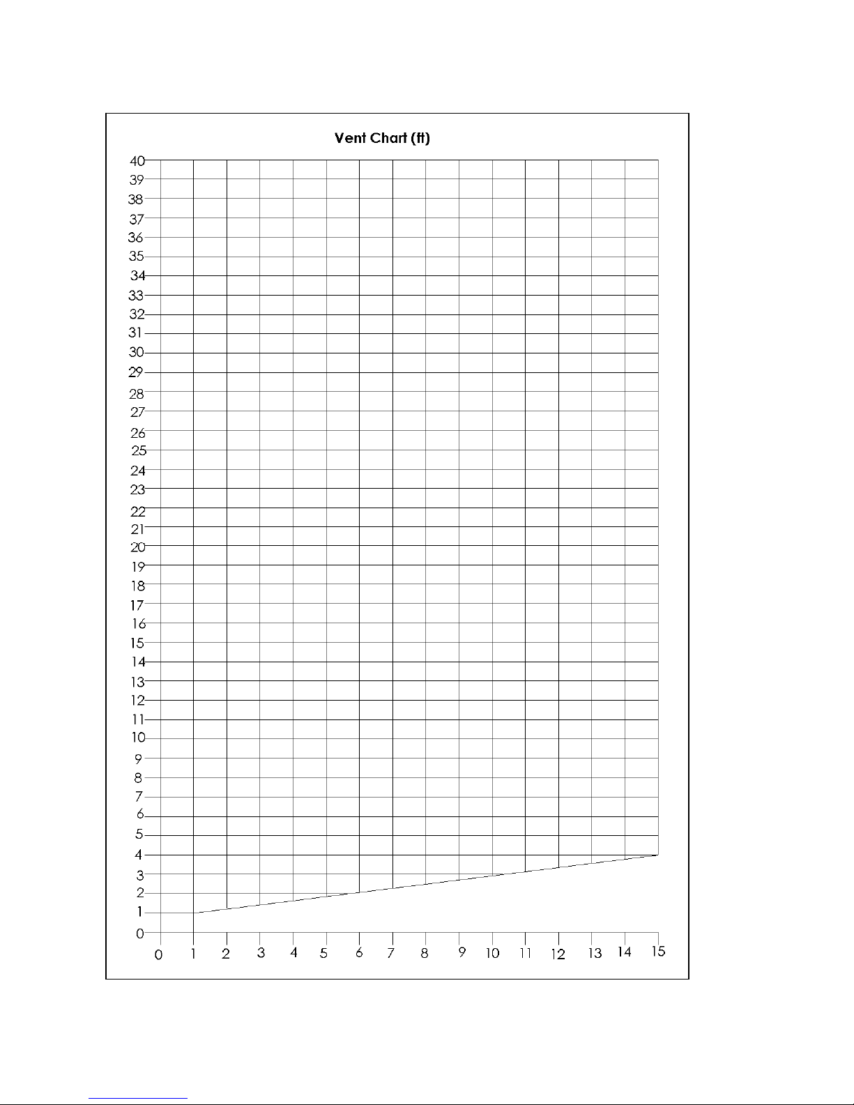
This model is certified for a maximum horizontal run of 15’ at 40’ vertical and a maximum vertical height of 40’.
Page 19 of 80
Page 20
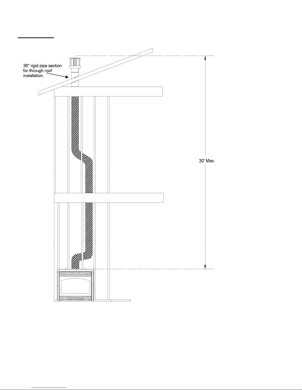
TYPICAL FLEX VENT INSTALLATIONS (continued)
Installation 1
With this installation a maximum of 4 - 90 degree and a maximum 30’ vertical with a maximum total
horizontal offset of 15’ may be used. The installer must use a wall thimble (part # IMC1082A)
wherever the venting passes through a wall, floor or ceiling. The installer must also provide any
support brackets and roof flashings that are required.
Page 20 of 80
Page 21

3.3.4 Direct Vent Information (continued)
Natural Gas EP Unit ONLY
Simpson Dura-Vent
The minimum vent system for horizontal termination must consist of:
Simpson Dura-Vent adapter Part # 0924N3 directly on top of unit
12" (300 mm)vertical length of vent
90 degree elbow
12" (300 mm) horizontal length of vent
Wall thimble part #IMC1082A
Horizontal termination cap 0984
The maximum horizontal vent system consists of:
Simpson Dura-Vent adapter Part # 0924N3 directly on top of unit
40' (12192 mm) vertical length directly on top of the stove
7 - 90 elbows (4 of the elbows allowed in horizontal plane)
28' (8534 mm) maximum horizontal length
Wall thimble part# IMC1082A
Horizontal termination cap 0984
The maximum vertical system consists of:
Simpson Dura-Vent adapter Part # 0924N3 directly on top of unit
Up to 40' (12192 mm) of vertical length
Fire stop
Flashing
Collar
Termination cap part # 0991
Security Venting
The minimum vent system for horizontal termination must consist of:
Simpson Dura-Vent adapter Part # 0924N3 directly on top of unit
12" (300 mm)vertical length of vent
90 degree elbow
12" (300 mm) horizontal length of vent
Wall thimble part #IMC1082A
Horizontal termination cap SV4CHC
The maximum horizontal vent system consists of:
Simpson Dura-Vent adapter Part # 0924N3 directly on top of unit
40' (12192 mm) vertical length directly on top of the stove
7 - 90 elbows (4 of the elbows allowed in horizontal plane)
28' (8534 mm) maximum horizontal length
Wall thimble part# IMC1082A
Horizontal termination cap SV4CHC
The maximum vertical system consists of:
Simpson Dura-Vent adapter Part # 0924N3 directly on top of unit
Up to 40' (12192 mm) of vertical length
Fire stop
Flashing
Collar
Termination cap part # SV4CGV
Page 21 of 80
Page 22

3.3.4 Top Vent - Direct Vent Information (continued)
Natural Gas EP Unit ONLY
Selkrik Direct-Temp Venting
The minimum vent system for horizontal termination must consist of:
Simpson Dura-Vent adapter Part # 0924N3 directly on top of unit
90 degree elbow
12" (305 mm) length horizontally
Wall thimble part #IMC1082A
Horizontal termination cap 4DT-HC
The maximum horizontal vent system consists of:
Simpson Dura-Vent adapter Part # 0924N3 directly on top of unit
40' (12192 mm) vertical length directly on top of the stove
90 degree elbow
15' (4572 mm) maximum horizontal length
Wall thimble part# IMC1082A
Horizontal termination cap 4DT-HC
The maximum vertical system consists of:
Simpson Dura-Vent adapter Part # 0924N3 directly on top of unit
Up to 40' (12192 mm) of vertical length
Fire stop
Flashing
Collar
Termination cap part # 4DT-VC
Use a ceiling fire stop when penetrating a ceiling or floor. Use a wall thimble when penetrating an
inside wall or outside wall. Vent terminals shall not be recessed into a wall or siding.
Page 22 of 80
Page 23

3.3.4 Direct Vent Information (continued)
Natural Gas EP Unit ONLY
2-Ply Aluminum Flex Vent
The minimum vent system for horizontal termination must consist of:
10” (254 mm) vertical length (measured to center of vent pipe) with a 90 degree bend and a
10” (254 mm) horizontal length (measured from center of vent pipe)
Wall thimble part# IMC1082A
Horizontal termination cap part # IMC1070A or IMC1070B
The maximum horizontal vent system consists of:
40’ (12192 mm) vertical length with a 7 - 90 degree bends (4 of the elbows allowed in
horizontal plane)and a 28’ (8534 mm) horizontal length (measured to center of vent pipe)
Wall thimble part# IMC1082A
Horizontal termination cap part # IMC1070A or IMC1070B
Note: Horizontal venting shall be supported, by means of a steel strap, every 3’.
The maximum vertical system consists of:
Up to 40' (12192 mm) of vertical length
Fire stop
Flashing
Collar
Adapter from flex to Simpson Dura-Vent part #P574
Termination cap part # 0991
A maximum of 4 – 90 degree bends can be used on the vertical installation with the flex vent. The
maximum height for this vent configuration is 40’ (12192 mm) and the minimum height is 4’ (1200
mm), the maximum horizontal run is a total of 28’ (8534 mm).
When fastening the flex vent to the termination and to the unit use a minimum of 3 # 8 x ½” hex head
sheet metal screws on the 4” vent and a minimum of 4 - # 8 x ½” hex head sheet metal screws on the
7” vent.
Page 23 of 80
Page 24
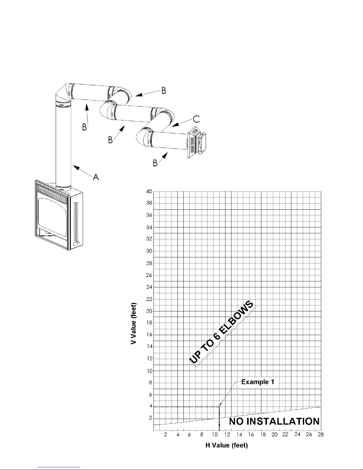
Direct Vent Information (continued)
Natural Gas EP Unit ONLY
Horizontal Vents
Acceptable Configurations
Example 1
V Value = A (4') = 4'
H Value = 3B (3 x 2') + C (3') = 11'
V Value = Total length of all vertical
sections in feet.
H Value = Total length of all horizontal
sections in feet.
NOTE:
a) for H & V values for 45
venting see Chart IV.
b) elbows are not counted in H
or V values.
c) vent chart starts from the top
of the unit.
Page 24 of 80
Page 25

Direct Vent Information (continued)
Natural Gas EP Unit ONLY
Vertical Vents
Acceptable Configurations
Example 1
V Value = A (4') + C (3') = 7'
H Value = 2B (2 x 2') = 4'
V Value = Total length of all vertical sections in
feet.
H Value = Total length of all horizontal sections in
feet.
NOTE:
a) for H & V values for 45 venting see
Chart IV.
b) elbows are not counted in H or V
values.
c) vent chart starts from the top of the
unit.
Page 25 of 80
Page 26
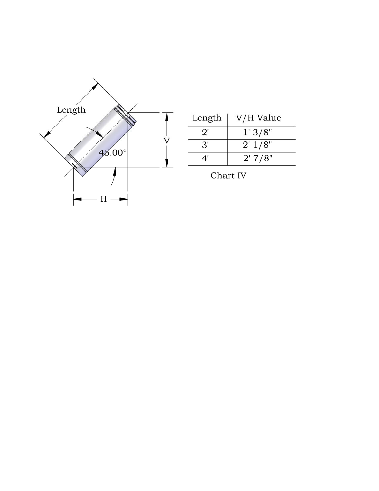
Direct Vent Information (continued)
Natural Gas EP Unit ONLY
Chart IV
Page 26 of 80
Page 27

Typical Simpson Dura- Vent Installation:
Vent terminals shall not be recessed into a wall or siding.
Figure 6
Page 27 of 80
Page 28
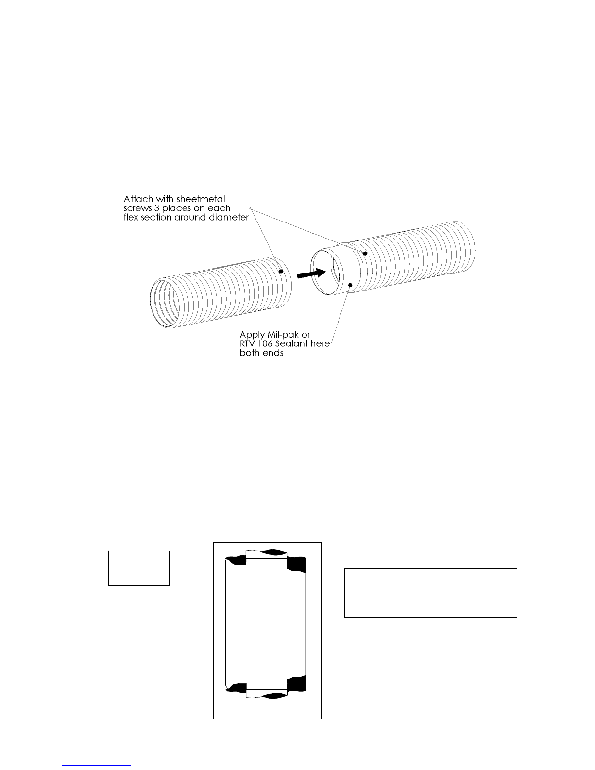
USE OF COUPLERS – WITH FLEX PIPE
In the event of a puncture of the vent pipe or if an extension is needed couplers may be used on both
the 4” and 7” flex vent. High temperature sealant shall be applied to the ends of the coupler and then
the coupler shall then be inserted into the flex vent. For the 4” vent 3 #8 x ½” hex head sheet metal
screws shall be used on each end of the joint to fasten the coupler to the venting. On the 7” vent a
minimum of 4 #8 x ½” hex head sheet metal screws shall be used. See Figure 7.
Figure 7
USE OF SEALANT
Sealant is required on vent system joints. On longer vent runs, especially vertical runs, sealant will
ensure that the combustion air enters from outdoors, and not through the vent joints. Use high
temperature sealant, available from local suppliers, on the inner pipe joint, applying the sealant
around the outside of the male part of the vent. A bead of silicone should be used on the outside of
the joint after assembly to seal the supply air. If the venting is disconnected for servicing, be sure to
follow above instructions for resealing venting when reconnecting to system.
“WARNING: A minimum clearance to combustibles must be maintained around the vent pipe of 1” on
horizontal pipe runs and 1” on vertical pipe runs.
Figure 8
Apply RTV high temperature
sealant around male pipe.
Page 28 of 80
Page 29

VENT RESTRICTOR INSTALLATION
Decorative Unit Restrictors
Vent Configuration Restrictor Size Width (inches)
40' vertical x 15' horizontal 75% 3.35"
20’ – 30’ 80% 3.48”
12’ – 20’ 70% 3.14”
6’ – 12’ 50% 2.5”
below 6’ none N/A
Heater Unit Restrictors
Vent Configuration Restrictor Size Width (inches)
20’ – 30’ 55% 2.66”
12’ – 20’ 50% 2.5”
6’ – 12’ 25% 1.7”
below 6’ none N/A
Vent Restrictor
Page 29 of 80
Page 30

Direct Vent Information (continued)
Natural Gas EP Unit ONLY
Page 30 of 80
Page 31
Direct Vent Information (continued)
Natural Gas EP Unit ONLY
Page 31 of 80
Page 32

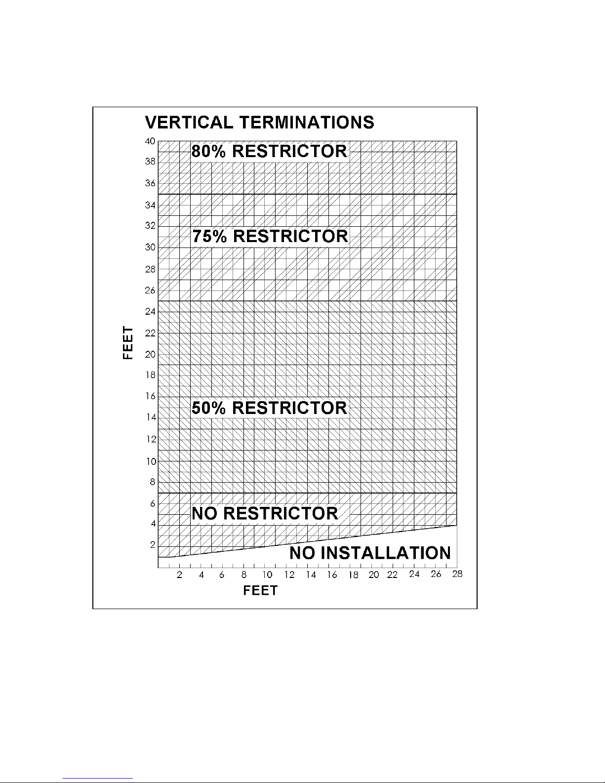
VENT RESTRICTOR INSTALLATION
Natural Gas EP Unit ONLY
Vent Configuration Restrictor Size Width
(inches)
35' - 40' vertical 80% 3.48"
25' vertical 75% 3.35"
7' vertical 50% 2.5"
40' vertical x 28' horizontal & 4 vertical elbows 80% 3.48”
25' vertical x 28' horizontal & 4 vertical elbows 75% 3.35”
7' vertical x 28' horizontal & 4 vertical elbows 50% 2.5”
Below 7' none n/a
40' vertical x 28' horizontal & 7 elbows (4 in horizontal plane) 50% 2.5"
12' vertical x 28' horizontal & 7 elbows (4 in horizontal plane) 50% 2.5"
4' vertical x 28' horizontal & 7 elbows (4 in horizontal plane) none n/a
4' vertical x 28' horizontal & 1 elbow none n/a
1' vertical x 1' horizontal & 1 elbow none n/a
Page 32 of 80
Page 33

VENT RESTRICTOR INSTALLATION (continued)
The restrictors are installed by removing the 2 screws on the ceiling of the firebox, place the desired restrictor
in place and using the screws to fasten the restrictor to the firebox. If you are installing a heater unit, you must
first remove the firebox baffle (4 screws) before installing the desired restrictor. Return the firebox baffle after
installing the restrictor. See Figure 9.
Figure 9
Page 33 of 80
Page 34

Horizontal Wall Vent Terminations
The position of the horizontal vent termination must be positioned in such a way as to meet all local building
codes. Attach the correct length of pipe. Mark the center line of the pipe facing the wall (allowing for a 1/4”
rise per foot of horizontal, example 10 ft of horizontal would require a rise of 2.5”).
NOTE: ALLOWING THE VENT PIPE TO SLOPE DOWN TOWARDS THE VENT TERMINATION COULD
CAUSE POOR COMBUSTION AND/OR HIGH TEMPERTURES THAT MAY PRESENT A FIRE HAZARD.
Mark a 9” x 9” square around the center mark (inside dimensions). Cut and frame the exterior wall to accept
the wall thimble. Install the wall thimble, on the inside of the exterior wall, shield using wood screws.
Attach the venting to the termination using sheet metal screws, for Z-Flex installations a Inca Metal Cutting’s
termination part # IMC1070A or IMC1070B shall be used and when using Simpson Dura-Vent or Security
Venting a Simpson Dura-Vent termination part # P574 shall be used. If termination is to be installed on vinyl
siding using vinyl siding standoff part # IMC1151.
To install the termination attach the 4” exhaust to the termination and fasten with 3 #8 x ½” hex head sheet
metal screws then attach the 7” vent to the termination and fasten with 4 #8 x ½” hex head sheet metal screws,
be sure that the flex vent overlaps the termination collars a minimum of 2”. Then attach the termination to the
exterior wall using four wood screws through the holes in the corner of the vent terminal.
The next step is to apply a bead of mil-pac or RTV 106 to top of the 4” exhaust collar on the unit and attach the
4” vent using screws (as described above), finally apply a bead of mil-pac or RTV 106 to top of the 7” vent and
attach (as described above).
Vertical Installations
Always maintain a 1” clearance around the vent pipe (vertical) and 1” clearance horizontal, when passing
through ceilings, walls, roofs, enclosures, attic rafter or any combustible surfaces.
DO NOT PACK AIR SPACES WITH INSULATION.
When passing through a flat ceiling install a Box/Wall thimble. Cut a 9” square hole and frame as shown in the
diagram opposite.
NOTE: ALWAYS CHECK YOUR LOCAL CODES BEFORE INSTALLING VENTING. CLE AR ANCES ETC, MAY VARY
FROM STATE TO STATE (PROVINCE TO PROVINCE).
NOTE: CONSULT DURAVENT PARTS LIST OR INCA METAL CUTTING’S FIREPLACE
MANUFACTURING PARTS LIST FOR PART NUMBERS.
See section 3.3.10 Venting for instructions on how to connect Security Venting or
Simpson Dura-vent.
9” x 9” opening
Page 34 of 80
Page 35

Termination above Roof
Consult local codes for minimum vent cap height above the roof (X), vent must be a minimum of 2’ from any
wall.
Figure 10
To prevent water seepage; install the flashing with upper portion slid under the roofing material and the lower
portion over the roofing material.
Note: Do not fasten down until the final adjustments to the vent have been made.
Page 35 of 80
Page 36

VENT TERMINAL LOCATIONS
Figure 11
V Vent Termination
A Air Supply Inlet
NOTE: All clearances are measured from the center of the termination (except item F).
A = clearances above grade, veranda, porch, deck, or balcony * 17-1/2" (445 mm) minimum
B = clearance to window or door that may be opened *17-1/2" (445 mm) minimum
C = clearance to permanently closed window *minimum 17-1/2" (445 mm) recommended to prevent
condensation on window
D = vertical clearance to ventilated soffit located above the terminal, within a horizontal distance of 24" (610
mm) from the centre-line of the terminal, 23-1/2" (597 mm) minimum
E = clearance to unventilated soffit 23-1/2" (597 mm) minimum
F = clearance to outside corner = 0" (0mm)
G = clearance to inside corner from centre of termination = 10-1/2" (267mm)
H = clearance to each side of center line above meter, in Canada 36" (914 mm) within a height 15' (4500
mm) above the meter assembly, for * U.S. follow ANSI Z223.1
I = clearance to service regulator vent outlet, for Canada 36" (914 mm) minimum, for * U.S. follow ANSI
Z223.1
J = clearance to non-mechanical air supply inlet to building or the combustion air inlet to any other
appliance *17-1/2" (445 mm) minimum
K = clearance to a mechanical air supply inlet, for Canada 77-1/2" (1969 mm) minimum , for * U.S. follow
ANSI Z223.1
L = clearance above paved side-walk or a paved driveway located on public property 89-1/2" (2273 mm)
minimum
M = clearance under veranda, porch, deck, or balcony * 17-1/2" (445 mm) minimum
a vent shall not terminate directly above a side-walk or paved driveway which is located between two single family dwellings and
serves both dwellings*
only permitted if veranda, porch, deck, or balcony is fully open on a minimum of 2 sides beneath the floor*
* as specified in CGA B149 Installation Code (1991) NOTE: local codes or regulations may specify different clearances
* follow ANSI Z223.1 for U.S.A.
Page 36 of 80
Page 37

3.3.5 CERAMIC LOG INSTALLATION – TUBE BURNER
The log tray has 4 tabs (2 front, 2 back) for positioning the rear log and the main front log.
Position rear log on rear log pins.
Page 37 of 80
Page 38

3.3.5 CERAMIC LOG INSTALLATION (continued)
Position front log on front log pins.
Position front right twig on log pin and move right side of twig until it contacts the front lip of the log
tray.
NOTE: The E unit is available with the above 3 log installation or with the additional twigs shown on
the following page. If using the 3 log installation remove the twig positioning pins which are visible in
the picture directly above this statement.
Page 38 of 80
Page 39

3.3.5 CERAMIC LOG INSTALLATION (continued)
Position left twig on the pins located on the front and rear logs, note that the wye portion of the twig is
facing the rear of the unit .
Position right twig on the pin located on the rear log and move the twig until it is resting against the
front twig.
Page 39 of 80
Page 40

MAIN BURNER FLAME PICTURE
Decorative (E-Unit)
Page 40 of 80
Page 41

3.3.5 CERAMIC LOG INSTALLATION – PAN BURNER
The log tray has tabs (2 front, 2 back) for positioning the rear log and the main front log.
Position rear log on rear log pins.
Page 41 of 80
Page 42

3.3.5 CERAMIC LOG INSTALLATION – PAN BURNER (continued)
Position right front log on front log pins.
Position front left twig on log pins.
Page 42 of 80
Page 43

3.3.5 CERAMIC LOG INSTALLATION – PAN BURNER (continued)
Position far left twig on the pin located on the bottom twig and angle as shown.
Position right "Y" twig on the pins located on the rear log and move the twig until it is resting on the
front twig.
Page 43 of 80
Page 44

3.3.5 CERAMIC LOG INSTALLATION – PAN BURNER (continued)
Position left "Y" twig on the pins located on the front and rear logs, note that the wye portion of the
twig is facing the rear of the unit .
Position center "Y" twig on the pins located on the right front log and left twig, note that the wye
portion of the twig is facing the left side of the unit.
Page 44 of 80
Page 45

MINERAL WOOL & EMBER INSTALLATION – PAN BURNER
Tasman HP
For illustration purposes logs are shown without center twig.
The Tasman HP is able to be operated with mineral wool & embers for additional flame effect. The
mineral wool is inserted between the logs and a containment barrier, which is part of the burner. The
other areas, shown along the front of the burner, may have other burner media such as embers or
“lava rock”, etc. installed. There is a lip on the front of the burner, the burner media is placed
between this lip and the mineral wool barriers. Note: Only the mineral wool is to cover the burner
ports. Mineral wool may also be placed in the ember area if desired.
Page 45 of 80
Page 46

MINERAL WOOL & EMBER INSTALLATION – PAN BURNER
Tasman EP
For illustration purposes logs are shown without center twig.
The Tasman EP is able to be operated with mineral wool & embers for additional flame effect. The
mineral wool is inserted between the logs and a containment barrier, which is part of the burner. The
other areas, shown along the front of the burner, may have other burner media such as embers or
“lava rock”, etc. installed. There is a lip on the front of the burner the burner media is placed between
this lip and the mineral wool barriers. Note: Only the mineral wool is to cover the burner ports.
Mineral wool may also be placed in the ember area if desired.
Page 46 of 80
Page 47
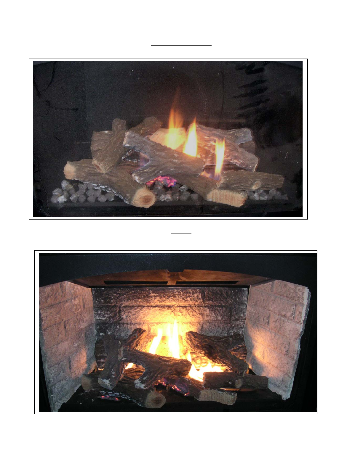
PAN BURNER FLAME PICTURE
Decorative (E-Unit)
H-Unit
Page 47 of 80
Page 48

3.3.6 Door Installation
Fit the top door slots over the brackets on each side of the top of the firebox, locate the two bottom
clasps and close. See Figure 12.
Pull the top of the window forward and release. Make sure the door returns to it’s original position.
This ensures that the door safety device is working properly.
Removal is reverse order.
If the glass has been damaged or broken it is highly recommended that you contact a qualified
service person. Remove the broken pieces (be sure to wear gloves) and remove door. See the
replacement parts list, at the end of the manual, you will require one 6 mm tempered glass panel (part
# IMC1010). Next you will install the glass gasket (part # 6AL) around the perimeter of the glass
panel, this gasket has an adhesive edge which is adhered to the glass while the rounded edge of the
gasket is folded over the edge of the glass. Lay a thin bead of high temperature silicone (part #
RTV106) around the inside perimeter of the door frame and with the rounded edge facing into the
door place the glass panel back into the door frame. Then follow the instructions above to re-install
the door.
Figure 12
Page 48 of 80
Page 49

WARNING: Do not operate appliance with the glass front removed, cracked or broken.
Replacement of the glass should be done by a licensed or qualified service person.”
Only doors certified with the appliance shall be used.
Do not use substitute materials.
Do not abuse glass doors by striking or slamming shut.
Do not operate with broken glass.
Page 49 of 80
Page 50

3.3.7 INITIAL FIRING
When lit for the first few times, the appliance may emit an odour resulting from evaporation of paint
and lubricants used in the manufacturing process. Open a door or window for ventilation. Anyone
with a respiratory condition may need to leave the room during the initial firings.
NOTE: It is normal for the appliance to expand and contract while it heats up or cools down
whether this is from a cold start or a steady-state condition where the fan has come on
or off. Under these circumstances it is possible that the expansion/contraction of the
metal parts may produce sounds.
Occasionally, after a cold start, vapor may condense and fog the glass, and the flames may be
partially blue. After a few minutes the moisture will disappear and the flames will become yellow.
Visually check the flame after warm-up (see flame pictures on page 31).
Figure 13
3.3.8 MANIFOLD PRESSURE REGULATOR ADJUSTMENT
The manifold pressure regulator controls gas input and flame height, and is pre-adjusted at the
factory. No further adjustment is required. Manifold pressure can be verified only (see Lighting
Instructions).
PILOT FLAME ADJUSTMENT
For proper operation, the pilot and main burner flames must be steady and not lifting off or floating.
The top 3/8” – 1/2” (10-13mm) of the thermopile should be engulfed by the pilot flame, see Figure 13.
Page 50 of 80
Page 51

PRIMARY AIR ADJUSTMENT
Aeration is factory set but may need adjustment for altitude or movement during shipping. To adjust
the air shutter loosen the screw on the bottom of the valve tray and slide the shutter bolt right or left to
suit (see Figure 14). Sliding the lever to the right closes the air shutter making the flame taller and
more colorful, sliding the lever to the left opens the air shutter this brings down the flame height and
reduces flame color.
Caution: Parts requiring adjustment during operation may be hot.
Note: Burner and bottom of firebox only shown for illustration purposes.
Factory Setting
Natural Gas – closed on E & H units
Propane Gas – closed on E unit, 50% on H unit
Figure 14
Aeration adjustment is important for the correct functioning of the appliance. Carbon build up, flame
lifting or any malfunction due to improper aeration adjustment during installation is not covered under
the factory warranty.
Page 51 of 80
Page 52

3.3.9 ALTITUDE ADJUSTMENT
All valves have been pre-set and certified for installation at elevations from 0 – 4500 feet (1 – 1372m)
above sea level.
When installing this unit at higher elevations, it is necessary to decrease the input rating by replacing
the existing burner orifice with a smaller size for installations over 4500 feet (1372m). The appliances
input should be reduced 4% for each additional 1000 feet (305m) above sea level. For the USA, derate the unit from sea level according to the gas installation code.
Page 52 of 80
Page 53

3.3.10 FIELD ASSEMBLED PARTS
OPTIONAL FAN INSTALLATION
The optional fan kit (part # IMC1057A) is available with a 45 mm fan. To install the optional fan you
will need to have 120 VAC run to a receptacle inside the unit. Remove the bottom louver and control
panel then slide the fan kit into place behind the valve and secure with 3 # 10 sheet metal screws in
the holes provided on each side. Plug the fan cord into the receptacle. A thermal snap disk is
provided to turn the fan on after the unit has run for approximately 5 – 10 minutes. The snap disk is
installed by sliding it into the holder on the bottom side of the valve tray. See Figure 2 for electrical
wiring schematic and Figure 17 for fan installation. Replace control panel and bottom louver.
Figure 17
Page 53 of 80
Page 54

3.3.10 FIELD ASSEMBLED PARTS (continued)
LOUVERS
The louvers are simple to install, the bottom & top louvers hang on brackets located at each side of
the appliance. See Figure 18.
Figure 18
Page 54 of 80
Page 55

3.3.10 FIELD ASSEMBLED PARTS (continued)
Optional Bay Fronts
The appliance is available with 2 optional bay fronts:
IMC1027A
IMC1013A
Page 55 of 80
Page 56

3.3.10 FIELD ASSEMBLED PARTS (continued)
Optional Bay Fronts
Both bay fronts are installed in the same way, simply remove the existing louvers and hang the bay
fronts in the slots which the louvers fit in see Figure 19.
Figure 19
Page 56 of 80
Page 57

VENTING
When Security Venting or Simpson Dura-Vent is to be used with the unit it will be necessary to install
an adapter to allow the 6-5/8” venting to connect to the unit which is factory assembled for connection
to 7” flex vent. The adapter (part# 0924N3) fits over the exhaust & air inlet collars on the top of the
appliance and is fastened in place with sheet metal screws. See Figure 20.
Twist lock procedure: Four indentations, located on the female ends of pipes and fittings, are
designed to slide straight onto the male ends of adjacent pipe and fittings. Orient the four pipe
indentations so they match and slide into the four entry slots on the male ends (see Figure 22).
Push the pipe sections completely together then twist lock one section clockwise approximately one
quarter turn until the two sections are fully locked.
In vertical installations which use flex vent it is necessary to install an adapter (part # P574) at the end
of the venting to allow connection to the Simpson Dura-Vent termination part # 0991 or Security
Venting part# SV4CGV. The adapter fits into the flex vent and is secured in place using sheet metal
screws. See Figure 21.
Horizontal runs of vent must be supported every three feet. Wall straps are available for this purpose.
High temperature sealant is required on each joint, run a 1/8” bead of sealant around the male end of
the outer sleeve, as shown in Figure 22, and twist lock the pipes or fittings together.
Figure 20 Figure 21
Page 57 of 80
Page 58

VENTING (continued)
Figure 22
Page 58 of 80
Page 59

4.0 MAINTENANCE
4.1 MAINTENANCE SAFETY
Turn off the gas to the main burner and allow the heater to cool for up to 30 minutes before
servicing.
Service and repair should be done by a qualified service person. The appliance should be inspected
before use and at least annually by a professional service technician. More frequent cleaning may be
required due to excessive lint from carpeting, bedding material, etc. It is important that the access
door compartment, burner, and circulating air passageways be kept clean to provide for adequate
combustion and ventilation airflow. Do not substitute materials or use components other than factory
supplied.
4.2 RECOMMENDED SERVICE
1. The venting system should be annually inspected by a qualified agency.
2. Visually check the burner and pilot flames occasionally. Visually inspect height and color of
flames (see Figure 13 & page 31).
3. Clean the glass as needed. See section 4.3 for instructions on glass cleaning.
4. Have the appliance inspected annually by a professional service technician.
5. Clean the appliance regularly.
Annual service: An annual service call should take between 1 – 2 hours. Start by disassembling the
unit; take off the door and remove all the glass embers, burner, and fan (if so equipped). A small
toothbrush is a handy tool for cleaning the fan. Loosen all the debris on the fan blades and vacuum it
off. Vacuum the whole firebox and all the air passages. Clean the burner, pilot orifice, main orifice,
etc.. After everything is clean, check all the connections and the chassis ground and reassemble.
Fire up the unit and check the electrical readings of the thermopile/thermocouple. Clean the glass.
Check the gas pressure.
4.3 GLASS CLEANING
The inside of the glass may require periodic cleaning to remove deposits left from impurities in the
gas and combustion air. For best results, use a tempered glass cleaner or polish. A suitable cleaner
is available from your dealer. Avoid the use of ammonia based cleaners such as Windex®. Do not
clean while hot. Do not use abrasive cleaners. Make sure you clean off any white film on the
fireplace glass as soon as possible – otherwise the glass may deteriorate.
Page 59 of 80
Page 60

4.4 BURNER & PILOT CLEANING
Periodic cleaning is necessary for proper operation.
Refer to section 4.7, remove the burner, and check that the burner orifice is clean.
Visually inspect the pilot. Brush or blow away any dust, lint, or foreign debris. If the pilot orifice is
plugged, disassembly may be required to remove any foreign material from the orifice or tubing.
When the appliance is back in service, check the pilot flame pattern with the figures in Section 3.3.8.
For re-lighting, refer to the lighting instructions in Section 2.1.
4.5 OPTIONAL FAN INSTALLATION
See instructions which are included with optional fan kit in section 3.3.10.
“Caution: Label all wires prior to disconnection when servicing controls. Wiring errors can cause
improper and dangerous operation. Verify proper operation after servicing.”
4.6 VALVE AND PILOT ASSEMBLY REPLACEMENT
The following procedure is to be performed by qualified service personnel ONLY. Turn off the
gas supply and allow the heater to cool for up to 30 minutes.
1. Turn off the gas at the meter.
2. Remove the door.
3. Remove the logs and log tray.
4. Remove the burner by loosening the screws and lifting it out.
5. Disconnect the gas line to the appliance and disconnect the gas line from the valve to the main
orifice.
6. Remove the screws holding the valve bracket to the base of the unit and lift valve & valve bracket
out.
7. Undo the pilot gas line and thermocouple connections at the gas valve and unplug piezo igniter.
8. Disconnect the thermostat or on/off switch wires from the valve (if applicable).
9. Remove the gas line to the valve inlet and outlet.
10. Remove the screws which hold the valve to the valve bracket.
11. Remove the screws fastening the pilot assembly to the pilot bracket and remove the pilot
assembly.
12. Reassemble the components in reverse order.
Page 60 of 80
Page 61

5.0 TROUBLE SHOOTING
SYMPTOM
POSSIBLE CAUSE
CORRECTIVE ACTION
I. Pilot will not light after
repeated triggering of the
piezo ignition button
A. No spark at electrode (weak or not heat source for pilot ignition)
1. Improper ignition 1. Align the electrode with 1/8” (3mm) gap
to pilot hood
2. Poor connections at starter
and ignition electrode
3. Broken ceramic cover on
ignition electrode
4. Defective piezo igniter 4. Replace piezo igniter
5. Poor grounding of piezo igniter 5. Tighten mounting nut and/or igniter
2. Reconnect if loose
3. Replace pilot assembly
screws
B. No gas or low gas pressure
1. Gas line shut off(s) may not be
turned on
2. Air in gas lines 2. Purge gas lines
3. Gas lines may not be
connected
4. Low pressure may be caused
by bent line
5. Valve control knob not fully
depressed in “PILOT” position
II. Pilot will not stay lit after
following the lighting
instructions
1. Weak or improperly located
2. Defective thermocouple 2. Replace thermocouple
3. Thermocouple not installed
4. Open wire connection in pilot
5. Defective Valve 5. Connect the millivolt meter probes to the
A. Thermocouple / Valve
pilot flame
properly
circuit
1. Turn on shut-off valves
3. Connect all gas lines
4. Check for a kinked line
5. Fully depress control knob
1. Adjust and clean pilot. The flame must
impinge on or engulf the thermocouple,
as shown in Figure 13
3. Make sure all wire connections at the gas
valve terminals are tight and the
thermocouple is fully inserted into the
mounting bracket
4. Check wire continuity and connections in
the pilot circuit
thermopile terminals on the gas valve.
Turn the valve to the “PILOT” position,
depress, and light. If the meter reading is
greater than 540 millivolts after 30
seconds, the thermopile is good. If the
pilot does not stay lie, the valve is
defective. Check section “B” below,
before replacing valve
Page 61 of 80
Page 62

following the lighting
instructions continued …
III. Main burner will not light
IV. Soot deposits on glass
V. Flame burns blue and lifts
off burner
VI. Main flame does not burn
properly
VII. Flames impinge on firebox
top
B. Defective safety circuit Pilot will not stay lit after
1. Loose or defective
connections
1. Check continuity, tighten wiring or
connections, and repair
A. Valve / Switches
1. Valve control off 1. Turn to “ON” position
2. Blockage at the burner (line,
orifice, or ports)
3. Defective wall switch or
thermostat
4. Defective wiring or
connections
5. Excessive length of thermostat
wire from valve to wall switch
or thermostat
6. Wall switch or thermostat
incorrectly wired
7. Defective Valve 7. Turn valve and “ON/OFF” switch to the
8. Thermopile may not be
generating sufficient voltage
(750 mV)
9. Wall switch, thermostat, or
wires are defective
1. Air inlet blocked or restricted 1. Clean air inlets
2. Vent system is restricted or
inadequate
1. Insufficient combustion air
being supplied
2. Manifold pressure set too high 2. Check manifold pressure
3. Vent system restricted 3. Check vent system
1. Incorrect vent or termination
used.
1. Vent system is restricted or
inadequate
2. Manifold pressure too high 2. Check manifold pressure as required
2. Check and clean
3. Conduct a continuity test or jumper wire
test and replace if defective
4. Conduct a test with a jumper wire and
repair as required
5. Reduce wire length to less than 100 feet
or increase wire size
6. Wire correctly
“ON” position. Check with millivolt meter
at terminals TP-TH. Millivolt meter
should read greater then 540 millivolts. If
the reading is OK and the burner does
not come on, replace the gas valve
8. Recheck using the millivolt meter. The
pilot flame may not be high enough for
the flame to properly engulf the
thermopile. If so, adjust and reset. If
voltage is still insufficient, replace
thermopile
9. Follow previous corrective action, check
switch and wiring. Replace where
defective
2. Confirm venting & termination are those
which are approved with the appliance
1. Ensure that no foreign material blocks air
inlets. Ensure the vent is adequate
1. Confirm venting & termination are those
which are approved with the appliance
1. Correct flue as required
Page 62 of 80
Page 63

6.0 REPLACEMENT PARTS
When requesting service or replacement parts for your unit, please provide model name and serial
number. All parts listed below may be ordered from an authorized dealer.
Description Part#
Door IMC1009
Door Retainer IMC1043
Upper Louvers IMC1012AU
Lower Louvers IMC1012AL
Burner Tray IMC1037
Burner IMC1036
Valve Bracket IMC1048
Fan Kit IMC1057A
Door Glass IMC1010
25% Restrictor IMC1084a
50% Restrictor IMC1084b
55% Restrictor IMC1084c
70% Restrictor IMC1084d
80% Restrictor IMC1084e
Door Glass Gasket 6AL
Pilot Assembly PSE-C4-519
Orifice P0505-48
Orifice P0505-57
Gas Valve (Honeywell) VS8420-E
Gas Valve (SIT) 0.820.634
Gas Valve (Robertshaw) 7000MVRB-5-LC
Piezo Igniter (R/S only) 1244-US
Door Latches 701S
Door Springs 10834-00480
Air Shutter IMC1041
Valve Tray (propane) IMC1040ELP
Back Log IMC1095
Right Front Log IMC1096
Left Front Log IMC1097
Left Twig IMC1098
Right Twig IMC1099
Intermittent Pilot & Remote Control Valve Parts
Description
Valve AF-4000
Hi/Low Knob AF-4000MH/L
Module AF-4000MOD
Module Wiring Harness AF-4000WH8PIN24
Motor Drive Battery Pack AF-4000BP
AC Adapter AF-4000ADP
Hi/Low Motor AF-4000MVH/L
Battery Back Up Pack AF-4000BBU
Hi/Low Solenoid AF-4000SH/L
Remote Control SP-1001, SP-1001H/L or SP-1001H/LTH
Intermittent Pilot PSE-NA266
Part#
Page 63 of 80
Page 64

6.0 REPLACEMENT PARTS (continued)
Additional parts for heater units
Description Part#
Rear Ceramic Panel IMC1049
Right Ceramic Panel IMC1050
Left Ceramic Panel IMC1051
Burner IMC1036A
Orifice P0505-37
Orifice P0505-53
Burner Tray IMC1037A
Firebox Baffle IMC1042
Door Glass IMC1010A
Burner Media IMC1200
Valve Tray (natural gas) IMC1040HN
Valve Tray (propane) IMC1040HLP
Skamol Panel – Left IMC1051SK
Skamol Panel – Right IMC1050SK
Skamol Panel – Rear IMC1049SK
Skamol Baffle IMC1042SK
Additional parts for pan burners
Description Part#
Pan Burner Assembly, E-Unit IMC1128A
Pan Burner Assembly, H-Unit IMC1128B
Log Tray E-Unit IMC1135A
Log Tray H-Unit IMC1135B
Rear Log (1) IMC1095
Left Large Twig (1) IMC1096
Front Small Twig (2) IMC1098
Wye Twig (3) IMC1099
Page 64 of 80
Page 65

7.0 INCA METAL CUTTING’S WARRANTY PROTECTION FOR
ALL INCA METAL CUTTING GAS FIREPLACE PRODUCTS
Inca Metal Cutting’s products are designed with superior components and materials, assembled by
trained craftsmen who take great pride in their work. The burner and valve assembly are leak tested
and test fired at a quality control test station. Once assembled the complete fireplace is thoroughly
inspected by a qualified technician, before packaging, to ensure that you, the customer, receives the
quality product that you expect from Inca Metal Cutting’s.
INCA METAL CUTTING’S GAS FIREPLACE’S WARRANTY
Your Inca Metal Cutting gas fireplace is guaranteed to be free of defects in materials and
workmanship for a period of 5 years from the date of purchase. This covers: combustion chambers,
heat exchangers and burners as well as stainless steel parts against tarnishing. Electrical (110 volt
and millivolt) components and wearable parts such as blowers, gas valves, thermal switches,
switches, wiring, remote controls, igniters, gaskets, glass and pilot assemblies are covered and Inca
Metal Cutting will provide replacement parts free of charge during the first year of the limited warranty
CONDITIONS AND LIMITATIONS
Inca Metal Cutting warrants its products against manufacturing defects to the original purchaser only
– i.e. the individual or legal entity (registered customer) whose name appears on the original invoice –
provided that the purchase was made through an authorized Inca Metal Cutting dealer and is subject
to the following conditions and limitations:
This factory warranty is nontransferable and may not be extended whatsoever by any of our
representatives.
A licensed, authorized service technician or contractor must have installed the gas fireplace.
Installation must be done in accordance with the installation instructions included with the product and
all local and national building and fire codes.
This limited warranty does not cover damages caused by misuse, lack of maintenance, accident,
alterations, abuse or neglect. Parts installed from other manufacturers will nullify this warranty.
This limited warranty further does not cover any scratches, dents, corrosion or discoloring caused by
excessive heat, abrasives, chemical cleaners nor any venting components used in the installation of
the fireplace.
This warranty does not cover any problems caused to installation used venting or vent terminations
which are not certified for use with this product.
Any installation, labor, construction, transportation or other related costs or expenses arising from
defective part(s), repair or replacement or otherwise of same, will not be covered by this warranty nor
shall Inca Metal Cutting assume responsibility for same. Further, Inca Metal Cutting will not be
responsible for any incidental, indirect or consequent damages, except as provided by law, and in no
event shall they exceed the original purchase price.
Page 65 of 80
Page 66

CONDITIONS AND LIMITATIONS (continued)
In the first year only, this warranty extends to the repair or replacement of warranted parts, which are
defective in material or workmanship provided that the product has been operated in accordance with
the operation instructions and under normal conditions.
After the first year, Inca Metal Cutting may, at its discretion, fully discharge all obligations with respect
to this warranty by refunding to the original warranted purchaser the wholesale price of any warranted
but defective part(s).
Notwithstanding any provisions contained in this warranty, Inca Metal Cutting’s responsibility under
this warranty is defined as above and it shall not in any event extend to any incidental, consequential
or indirect damages.
This warranty defines the obligations and liability of Inca Metal Cutting with respect to the Inca Metal
Cutting gas fireplace and any other warranties expressed or implied with respect to this product, its
components or accessories are excluded.
Inca Metal Cutting neither assumes, nor authorizes any third party to assume, on its behalf, any other
liabilities with respect to the sale of this product. Inca Metal Cutting will not be responsible for: over
firing, downdrafts, spillage caused by environmental conditions such as rooftops, buildings, nearby
trees, hills, mountains, inadequate vents, excessive venting configurations, insufficient make up air,
or negative air pressures which may or may not be caused by mechanical systems such as exhaust
fans, furnaces, clothes dryers, etc.
Any damages to fireplace, combustion chamber, brass or chrome trim or other component due to
water, weather damage, long periods of dampness, condensation, damaging chemicals or cleaners
will not be the responsibility of Inca Metal Cutting.
The bill of sale or copy will be required together with a serial number and a model number when
making any warranty claims from your authorized dealer.
Inca Metal Cutting reserves the right to have its representative inspect any product or part thereof
prior to honoring any warranty claim.
Page 66 of 80
Page 67

8.0 LABEL INFORMATION E - UNIT
Page 67 of 80
Page 68

9.0 LABEL INFORMATION (continued)
Keep burner and control compartment clean. See installation and operating instructions
accompanying appliance.
Sections of the venting system have not been installed. WARNING – Do not operate the
appliance until all sections have been assembled and installed in accordance with the
manufacturer’s instructions.
WARNING
Electrical Grounding Instructions
This appliance is equipped with a three prong (grounding) plug for your protection against shock
hazard and should be plugged directly into a properly grounded three prong receptacle. Do not cut or
remove the grounding prong from this plug.
Class IIIA-2
In Canada, also certified for installation in a bedroom or bedsitting room.
Termination Labels
ClassIIIA-1
Inca Metal Cutting’s Listed Vent Termination
Part #IMC1070A or IMC1070B
For Direct Vent Fireplace
Mfg. by Inca Metal Cutting Heating Products Ltd.
Unit 100 Sales and office #115 shipping
11091 Bridgeport Rd
Richmond BC, V6X 1T3
HOT
Class I
This side up
Page 68 of 80
Page 69

INSTRUCTIONS FOR TUBE BURNER UPGRADING TO HEATER UNIT
The specifications of the heater unit are:
ITEM NATURAL GAS (NG) PROPANE (LPG)
INPUT: Hi 32,000 Btu/hr (9.37 kW) 28,000 Btu/hr (8.20 kW)
INPUT: Lo 23,000 Btu/hr (6.74 kW) 22,000 Btu/hr (6.44 kW)
MANIFOLD PRESSURE: Hi 3.5” w.c. (0.87 kPa) 10” w.c. (2.49 kPa)
MANIFOLD PRESSURE: Lo 1.7” w.c. (0.42 kPa) 6.4” w.c. (1.57 kPa)
GAS INLET SUPPLY
PRESSURE:
Maximum: 13.5” w.c. (3.4 kPa) Maximum: 14” w.c. (3.49 kPa)
AIR SHUTTER
SETTING
ORIFICE SIZE: @ 0-4500’ # 34 DMS # 51 DMS
CONTROL VALVE TYPE: Honeywell , SIT 820 Nova,
VENTING 2-ply aluminum vent, Selkirk,
FAN * Optional * Variable Speed (120 Volt) Variable Speed (120 Volt)
Minimum: 5.0” w.c. (1.2 kPa) Minimum: 12” w.c. (2.99 kPa)
Robertshaw-Grayson or
Skytech AF-4000
Security or Simpson Dura-Vent
APPENDIX A
adjustable from open 1/16”
to fully open
adjustable from open 1/8”
to fully open
Honeywell , SIT 820 Nova,
Robertshaw-Grayson or
Skytech AF-4000
2-ply aluminum vent, Selkirk,
Security or Simpson Dura-Vent
Page 69 of 80
Page 70

The steps for upgrading the decorative unit to a heater unit are as follows:
1) Remove door (see page 32).
2) Remove logs, log tray and burner. Remove orifice and replace with appropriate orifice for heater
unit. Install heater burner & log tray.
Page 70 of 80
Page 71

3) Install burner media along front edge of log tray, media may protrude to the center of the front
burner holes and may be installed in any unused area along the front of the log tray. The picture
below shows approximately how far the embers should protrude into the flame.
4) Install firebox baffle with 2 screws into back wall of firebox and 2 screws into ceiling of firebox.
Page 71 of 80
Page 72

5) The first step for installing the ceramic brick panels is to place the rectangular shaped panel on the
log tray against the back wall of the firebox. Next slide, either, left or right panel into place, note that
the panel fits behind the ledge of the firebox baffle on the top and a bent up tab on the log tray on the
bottom. When both side panels are installed they will secure the rear panel in place.
7) The final step will be to replace the E unit, tempered glass, door with the H unit ceramic glass door.
Flame picture of heater unit
Page 72 of 80
Page 73

LABEL INFORMATION H – UNIT
Page 73 of 80
Page 74

APPENDIX B (CONVERSION KITS)
This kit will convert the fireplace to Natural Gas / Propane (as applicable). In order to convert this unit
to an alternate gas the valve tray assembly must be replaced as 1 piece.
The IMC100 models are designed to burn either natural gas or propane. Each unit leaves the factory
equipped for one specific fuel but it is simple to field convert the unit to an alternate fuel. The original
type of fuel is marked on the ratings label (see pages 50 & 56) of the manual.
“WARNING”
This conversion kit shall be installed by a qualified service
agency in accordance with the manufacturer’s instructions
and all applicable codes and requirements of the authority
having jurisdiction. If the information in these instructions is
not followed exactly, a fire, explosion or production of
carbon monoxide may result causing property damage,
personal injury or loss of life. The qualified service agency is
responsible for the proper installation of this kit. The
installation is not proper and complete until the operation
of the converted appliance is checked as specified in the
manufacturer’s instructions supplied with the kit.
This kit is for use with models Tasman ET & Tasman HT.
Conversion Kit Contents
This conversion kit contains the following parts:
1) Valve tray part numbers:
IMC1040EN (for natural gas E-rated units)
IMC1040ELP (for propane E-rated units)
IMC1040HN (for natural gas H-rated units)
IMC1040HLP (for propane H-rated units)
2) Conversion Kit labels
Page 74 of 80
Page 75

The proper steps for converting the appliance are as follows:
1) Caution the gas supply shall be shut off prior to disconnecting the electrical power, before
proceeding with the conversion.
2) Remove the door, ceramic logs, log tray and burner (see page 43 in the manual).
3) Remove the valve tray (see pages 43 in the manual).
4) Replace with desired valve tray (installation is the reverse of removal).
5) Verify the input of the converted appliance by checking the orifice size with the size specified on
the ratings labels found on pages 50 & 56 of the manual.
6) Replace burner, log tray, ceramic logs and door.
7) Leak test the appliance, with a soapy water solution, prior to placing the unit into operation.
8) Light appliance. See the Lighting Instructions, page 7, of the manual to verify normal operating
sequence of the ignition system.
9) Check that the manifold pressure is correct, see pages 3 or 52 of the manual.
10) Check that the minimum and maximum inlet gas pressures are correct, see pages 3 or 52 of the
manual.
See pages 30, 33 & 55 of the manual for proper pilot and burner flame pictorials.
Fill out and attach the fuel conversion label provided in the kit then apply label over top of existing
ratings label.
All valves have been pre-set and certified for installation at elevations from 0 – 2000 feet (1 – 608 m)
above sea level.
When installing this unit at higher elevations, it is necessary to decrease the input rating by replacing
the existing burner orifice with a smaller size for installations over 2000 feet (608 m). The appliances
input should be reduced 4% for each additional 1000 feet (305 m) above sea level. For the USA, derate the unit from sea level according to the gas installation code.
H-Unit Natural Gas
ALTITUDE (ft) ORIFICE #
2000 34
3000 34
4000 34
5000 34
6000 35
7000 35
8000 35
9000 36
10,000 36
Page 75 of 80
Page 76

H-Unit Propane Gas
ALTITUDE (ft) ORIFICE #
2000 51
3000 51
4000 51
5000 51
6000 53
7000 53
8000 53
9000 54
10,000 54
E-Unit Natural Gas
ALTITUDE (ft) ORIFICE #
2000 45
3000 45
4000 45
5000 45
6000 46
7000 46
8000 46
9000 47
10,000 47
E-Unit Propane Gas
ALTITUDE (ft) ORIFICE #
2000 57
3000 57
4000 57
5000 57
6000 58
7000 58
8000 58
9000 59
10,000 59
Page 76 of 80
Page 77

CONVERSION KIT MARKINGS
Class IIIA
Minimum inlet gas pressure 5.0” w.c. for natural gas
Minimum inlet gas pressure 11.5” w.c. for propane
Maximum inlet gas pressure 7.0” w.c. for natural gas
Maximum inlet gas pressure 14.0” w.c. for propane
Input rating 32,000/23,000 btu/hr for natural gas on Tasman HT unit
Input rating 18,000/12,500 btu/hr for natural gas on Tasman ET unit
Input rating 28,500/22,000 btu/hr for propane gas on Tasman HT unit
Input rating 15,000/12,500 btu/hr for propane gas on Tasman ET unit
Conversion kits part #TNG1 for NG & #TLPG1 for LPG are for use with models Tasman ET or
Tasman HT natural gas or propane gas.
Class IIIA
This appliance was converted d/m/y to _____ gas with kit #TNG1 or TLPG1 by (name and address of
organization making the conversion), which accepts the responsibility that this conversion has been
made properly.
Class IIIA
This control has been converted for use with ______ gas.
Exterior of the kit shall have the following markings:
1) Conversion kit part #
2) Appliance model #(s) for use with the kit
3) Type of gas to be converted to.
Page 77 of 80
Page 78

APPENDIX C (AMERICAN FLAME VALVE INFORMATION)
Page 78 of 80
Page 79

APPENDIX C (Continued)
Page 79 of 80
Page 80

APPENDIX C (Continued)
Special Features on the AF-4000 Module
The AF-4000 Module can be powered two different ways. The first is a standard 110 volt AC to 6.0
volt DC adaptor. This adapter is connected to the AF-4000 Module by connecting the two 1/4” female
terminals from the adapter to the two 1/4” male terminals, located on the AF-4000 Module , marked
POWER. The second method of powering the appliance is by using the AF-4000 BP battery pack.
The appliance will not have back up power, during power outages, if only the 6.0 volt adapter is used
however a battery back up package, AF-4000BBU, is available to be used in this situation.
The AF-4000 module has 2 special features built into the system.
1. Continuous Pilot Feature - This feature allows the user to change from a spark to pilot system to a
standing pilot system, for direct vent appliances during cold climate, to keep the firebox warm.
a) There is a switch located on the side of the AF-4000 module that reads “Continuous Pilot ON/OFF”,
this switch will allow the user to select the pilot mode of operation.
b) When the Continuous Pilot switch is in the OFF position and the appliance ON/OFF switch is
turned to ON the pilot will spark and light. When the appliance ON/OFF switch is turned OFF the pilot
will shut off when the main burner shuts off.
c) When the Continuous Pilot switch is in the ON position and the appliance ON/OFF switch is turned
on the pilot will spark and light. When the appliance ON/OFF switch is turned to OFF the pilot will
stay ON when the main burner shuts off. This setting is generally used in cold climates to keep the
firebox warm.
d) The Continuous Pilot mode can also be activated by an optional hand held remote control.
2. Remote Control Feature - The AF-4000 module has a built in remote control receiver. This allows
the user to program a hand held remote transmitter, wireless wall mount thermostat or wireless wall
mount switch to the appliance at any time during or after the installation of the appliance.
a) There is a switch located on the side of the AF-4000 module that reads REMOTE/OFF.
b) When the Remote/Off switch is in the OFF position the appliance will operate from an appliance
mounted rocker switch or wall switch connected to the (2) brown wires on the AF-4000 module.
c) When the Remote/Off switch is in the REMOTE position the appliance will operate from the
(optional) Remote Control transmitter, wireless wall mounted thermostat or wireless wall mounted
switch.
NOTE: The AF-4000 module must be programmed to the (optional) Remote Control transmitter,
wireless wall mounted thermostat or wireless wall mounted switch.
a) To program the AF-4000 locate the LEARN button on the AF-4000 module. Press and release
the LEARN button, the AF-4000 module will beep then press any key on the Remote Control. Once
the AF-4000 internal receiver accepts the transmitter code there will be a series of confirming beeps.
b) The Remote system is now ready for use.
Page 80 of 80
 Loading...