

Page 1

MODEL NO.:RSS52
Page
1
Professional Installation Recommended
Note: Approximate time of assembly is 30 min to 1 hour
PRINTED IN CHINA
READ AND SAVE THESE
INSTRUCTIONS
Installation Guide
MODEL NO.:
RSS52
Table of Contents:
Safety tips Pg.2
Unpacking your fan. Pg.3
Installation Preparation.Pg.4
Hanging Bracket Installation Pg.4
Tools and material required Pg.5
Electrical Outlet Box Pg.5
Bulb installation Pg.6
Fan Assembly Pg.7-8
Wiring Pg.8
Canopy Assembly Pg.9
Blade Assembly Pg.9
Light Kit Assembly Pg.10
Testing Your Fan Pg.10
Trouble Shooting Pg.11-12
Maintenance Pg.12
Page 2

MODEL NO.:RSS52
Page
2
SAFETY TIPS.
WARNING: To reduce the risk of electrical shock, turn off the electricity to the fan at the main fuse box or circuit
panel before you begin the fan installation or before servicing the fan or installing accessories.
1. READ ALL INSTRUCTIONS AND SAFETY INFORMATION CAREFULLY BEFORE INSTALLING YOUR
FAN AND SAVE THESE INSTRUCTIONS.
CAUTION: To avoid personal injury, the use of gloves may be necessary while handling fan parts with sharp edges.
2. Make sure all electrical connections comply with Local Codes or Ordinances, the National Electrical Code, and
ANSI/NFPA 70-1999. If you are unfamiliar with electrical wiring or if the house/building wires are different colors
than those referred to in the instructions. please use a qualified electrician.
3. Make sure you have a location selected for your fan that allows clear space for the blades to rotate. and at
least seven (7) feet (2.13 meters) of clearance between the floor and the fan blade tips. The fan should be mounted
so that the tips of the blades are at least thirty (30) inches (76 centimeters) from walls or other upright structures.
4. The outlet box and ceiling support joist used must be securely mounted, and capable of supporting at least
50 pounds (23 kilograms). The outlet box must be supported directly by the building structure.
Use only ETL listed outlet boxes marked "FOR FAN SUPPORT”.
WARNING: To reduce the risk of fire, electrical shock, or personal injury, mount to the outlet box marked
“Acceptable for Fan Support,” and use the mounting screws provided with the outlet box. Most outlet boxes
commonly used for the support of lighting fixtures are not acceptable for fan support and may need to be
replaced. Consult a qualified electrician if in doubt.
WARNING: To reduce the risk of fire, electrical shock, or personal injury, wire connectors provided with this fan
are designed to accept only one12 gauge house wire and two lead wires from the fan. If your house wire is larger
than 12 gauge or there is more than one house wire to connect to the two fan lead wires, consult an electrician
for the proper size wire connectors to use.
5. Electrical diagrams are for reference only. Light kits that are not packed with the fan must be ETL listed and
marked suitable for use with the model fan you are installing. Switches must be ETL general use switches. Refer to
the instructions packaged with the light kits and switches for proper assembly.
6. After installation is complete, check that all connections are absolutely secure.
7. After making electrical connections, spliced conductors should be turned upward and pushed carefully up
into the outlet box. The wires should be spread apart with the grounded conductor and the equipment-grounding
conductor on opposite sides of the outlet box.
WARNING: To reduce the risk of electrical shock, fire and to prevent humming noise do not use this fan with any
solid state speed control device or control fan speed with a full range dimmer switch. [Using a full range dimmer
switch to control fan speed will cause a loud humming noise from fan.] (Note: This fan is suitable for use with
remote control.)
8. Do not operate the reverse switch until fan has come to a complete stop.
9. Do not insert anything between the fan blades while they are rotating.
WARNING: To reduce the risk of personal Injury, do not bend the blade brackets when installing the brackets,
balancing the blades, or cleaning the fan. do not insert foreign objects in between rotating fan blades.
WARNING: To avoid personal injury or damage to the fan and other items, be cautious when working around or
cleaning the fan.
10. Do not use water or detergents when cleaning the fan or fan blades. A dry dust cloth or lightly dampened
cloth will be suitable for most cleaning.
WARNING: To reduce the risk of personal injury, use only parts provided with this fan. The use of parts OTHER
than those provided with this fan will void the warranty.
NOTE: The important safety precautions and instructions appearing in the manual are not meant to cover all
possible conditions and situations that may occur. It must be understood that common sense and caution are
necessary factors in the installation and operation of this fan.
Page 3
MODEL NO.:RSS52
Page
3
1. Unpacking Your Fan.
Carefully open the packaging. Remove items from
styrofoam inserts. Remove motor housing and place on
carpet or styrofoam to avoid damage to finish. Do not
discard fan carton or styrofoam inserts should this fan
need to be returned for repairs.
Check against parts inventory that all parts have been included.
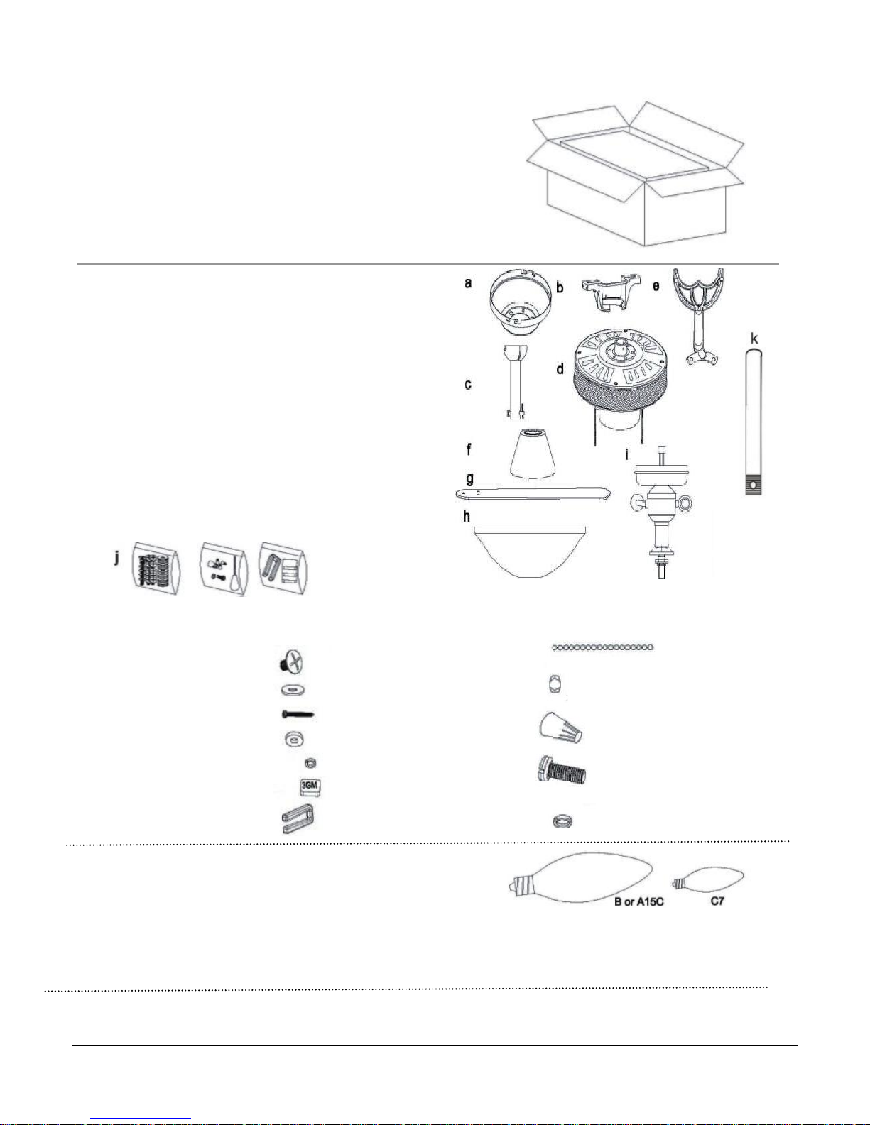
2. Parts Inventory.
a. Canopy: 1 piece
b. Hanging bracket (pre-attached to canopy): 1 piece
c. 4 in. down rod and hanging ball (with pin and clip)
1 piece
d. Motor housing: 1 piece
e. Blade arm: 5 pieces
f. Down rod cover:1 piece
g. Blade: 5 pieces
h. Glass shade: 1 piece
i. Light kit fitter: 1 piece
j. Component bags (below components are included)
k. 21in. Down rod
Blade screw: 16 pieces Pull chain fob: 2 piece
Paper washer: 16 pieces Waist beads: 4 pieces
Wood screw: 2 pieces Wire nuts: 3 pieces
Metal washer: 2 pieces
Small lock washer: 2 pieces Safety Bolt: 1 pieces
Balancing weight: 3 pieces
Plastic Clip: 1 pieces Large lock washer: 1 piece
Required bulbs:
Light kit- use – E12, Type B, 40W x 2 (Not Included)
Motor housing-use - E12, Type C, 7W x 4 (Not Included)
WARNING: DO NOT EXCEED INDICATED BULB WATTAGE
NOTE: Your fan is equipped with a wattage limiter, if you exceed the indicated wattage your ceiling fan will not function.
Page 4
MODEL NO.:RSS52
Page
4
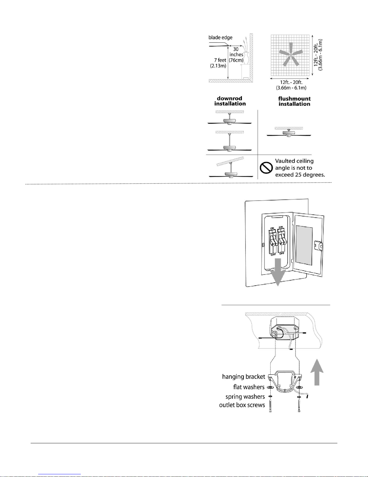
3. Installation Preparation.
To prevent personal injury and damage, ensure that
the hanging location allows the blade a clearance
of 7ft.(2.13m) from the floor and 30in.(76cm) from
any wall or obstruction.
The fan is suitable for room sizes up to 400 square
feet (37.2square meters).
This fan can be mounted with a down rod
on a normal or vaulted ceiling. The hanging length
can be extended by purchasing a longer down rod
(0.625in/1.59cm diameter).
This fan can also be mounted using
Flush mount installation only on a normal ceiling.
4. Hanging Bracket Installation.
Turn off circuit breakers to current fixture from breaker panel
and be sure operating light switch is turned to the OFF position.
WARNING: Failure to disconnect power supply prior to
installation may result in serious injury.
Remove existing fixture.
WARNING: When using an existing outlet box, be sure the
outlet box is securely attached to the building structure and can
support the full weight of the fan. Ensure outlet box is cleanly
marked “Suitable for Fan Support. " If not, it must be replaced
with an approved outlet box. Failure to do so can result in
serious injury.
CAUTION: Be sure outlet box is grounded properly and that a
ground wire (green or bare) is present.
Partially loosen screws in slotted holes of canopy. Remove
the other 2 screws (along with the star washers)--save for
later use. Twist canopy to remove hanging bracket.
Install hanging bracket to outlet box using original screws,
spring washers and flat washers provided with new or
original outlet box. If installing on a vaulted ceiling, face
opening of hanging bracket towards high point of ceiling.
Arrange electrical wiring around the back of the hanging
bracket and away from the hanging bracket opening.
Note: It is very important that you use the proper hardware when
installing the hanging bracket as this will support the fan.
Page 5
MODEL NO.:RSS52
Page
5
TOOLS AND MATERIALS REQUIRED
Phillip screw driver
Blade screw driver
Adjustable pliers or wrench
Step Ladder
Wire cutter
Electrical tape
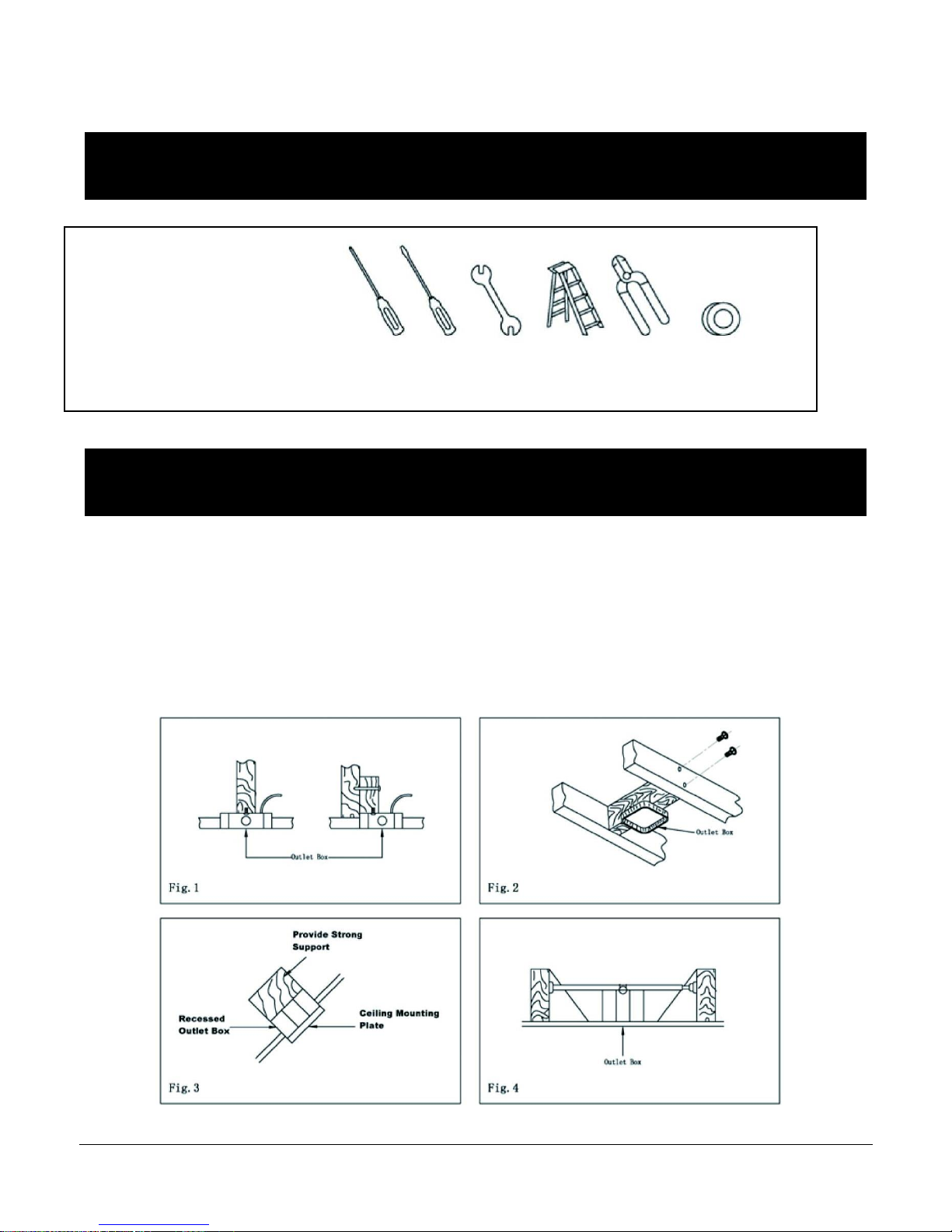
ELECTRICAL OUTLET BOX
1. If there is an existing outlet box, ensure it is clearly marked” Suitable For Fan
Support”. If not, it must be replaced with an approved one.
2. Secure the outlet box (or make sure the existing box is secured) directly to the
building structure. Use appropriate fasteners and building materials. Wood joist
and outlet box must be able to support a minimum of 50 pounds.
3. Figure 1,2 and 3 are examples of different ways to mount the outlet box in
different situations. A longer down rod may be required in sloped ceiling
situations to maintain proper blade clearance.
4. To hang the fan in locations where no ceiling joists is available. A hanger support
bar may be required (Fig. 4)
Page 6

MODEL NO.:RSS52
Page
6
BULB INSTALLATION
Installing bulbs in the motor housing, locate
the four access plates on the motor housing
top. Remove two screws per access plate to
reach each socket, use phillips screwdriver.
Install each candelabra base Type C, 7W
bulbs (Not Included). Reattach the access
plates.
CAUTION - Refer to the Maximum Wattage Caution
Label located near the lamp holder for
recommended maximum wattage-do not
exceed recommended wattage.
WARNING - Do not attempt to replace the bulbs
while the line breaker is in ON position.
BULB INFO: E12, Type C, 7W x 4 (Not Included)
WARNING: DO NOT EXCEED INDICATED BULB WATTAGE
NOTE: Your fan is equipped with a wattage limiter, if you exceed the indicated wattage your ceiling fan will not function.
6. Flush Mount Assembly
1. Remove round rubber ring from the canopy
2. Thread electrical wire through the canopy.
3. Remove every other screw on the motor housing
total of 3 screws.
4. Attach the canopy to the motor housing with the 3
screws.
5. Continue to step 8 for wiring without the remote
control. Then install the assembled motor housing
along with the canopy to the hanging bracket. Continue
to step 10.
6. If you are installing the remote control (sold
separately), read Remote Installation
Instructions, then install the assembled motor housing
along with the canopy to the hanging bracket, then continue to step 10.
Page 7
MODEL NO.:RSS52
Page
7
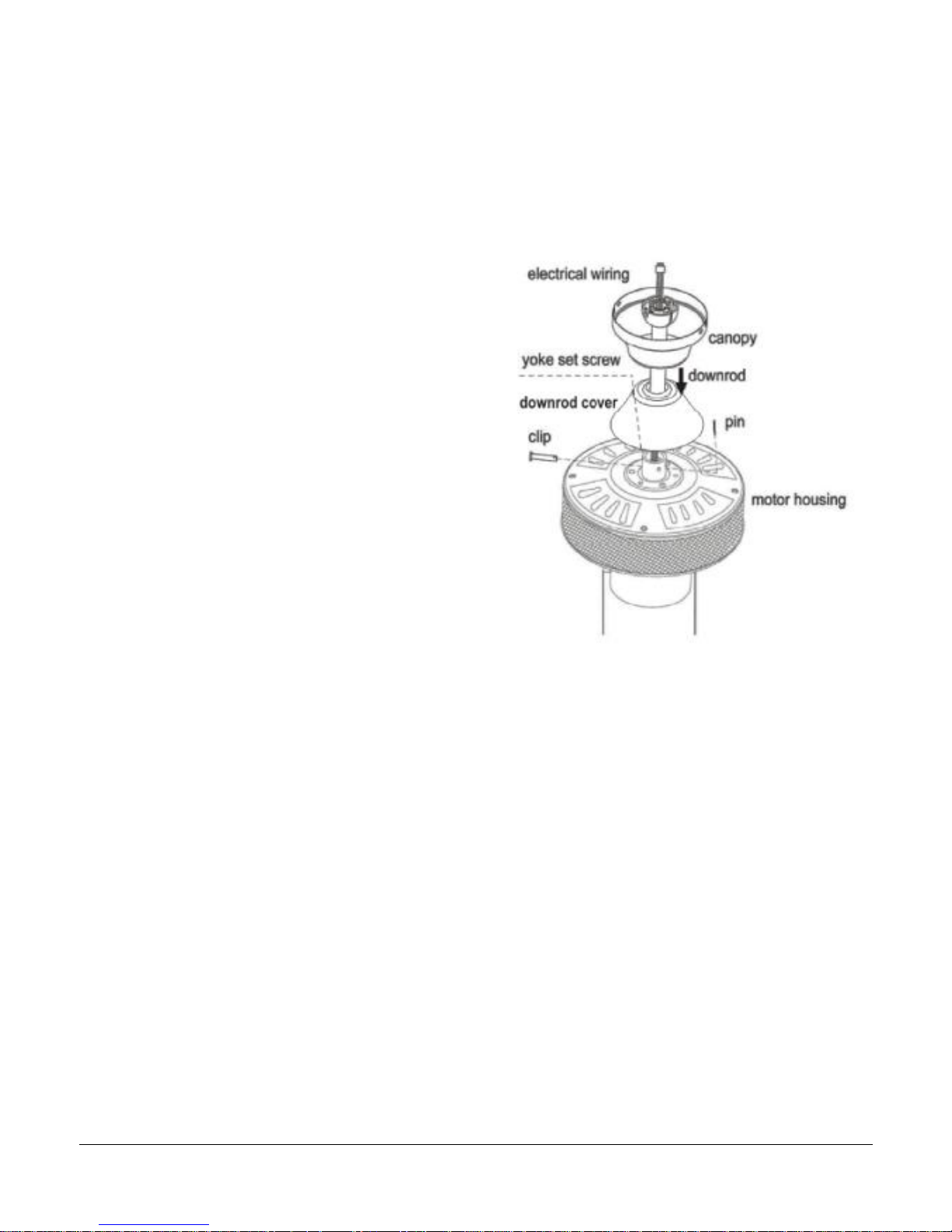
7 . Fan Assembly with Down Rod
- Choose the 4” or 21” Down Rod -
Remove pin and clip from down rod (if you have
not already done so). Slide down rod through
canopy, and down rod cover.
Thread electrical wires through downrod and
Pull extra wire slack from the upper end of the
downrod.
Tip: Apply small piece of electrical tape to the
ends of the electrical wires to keep them
together when threading them through the
down rod.
Loosen yoke set screws and nuts. Place down rod
into the motor housing yoke and re-insert pin
and clip that were previously removed. Tighten
yoke set screws and nuts securely.
["Fan Assembly continued on next page.]
NOTE: The important safety precautions and
instructions appearing in the manual are not
meant to cover all possible conditions and
situations that may occur. It must be understood
that common sense, and caution are necessary
factors in the installation and operation of this fan.
Page 8
MODEL NO.:RSS52
Page
8
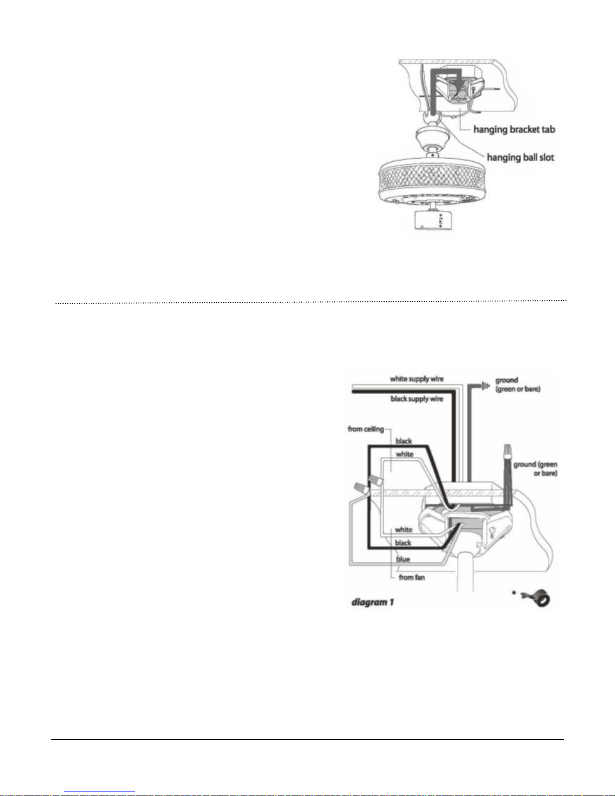
Fan Assembly with down rod. (cont.)
With the hanging bracket secured to the outlet
box and able to support the fan, you are now
ready to hang your fan. Grab the fan firmly with
two hands. Slide down rod through opening in
hanging bracket and let hanging ball rest on the
hanging bracket. Turn the hanging ball slot until it
lines up with the hanging bracket tab.
Tip: Seek the help of another person to hold the
stepladder in place and to lift the fan up to you
once you are set on the ladder.
Continue to “Wiring” section for wiring diagram.
8. Wiring.
Important: Be sure outlet box is properly grounded or that
a ground wire (GREEN or bare) is present.
Make sure all electrical connections comply with Local
Codes or Ordinances and the National Electrical Code. If you
are
unfamiliar with electrical wiring, or if the house/building
wires are different colors than those referred to in the
instructions, please use a qualified electrician.
When down rod is secured in place on the hanging bracket,
electrical wiring can be made. If you installing the remote control
(sold separately) read Remote Installation Instructions. Then
continue to canopy assembly. Continue reading if remote is not
being installed. (diagram 1) as follows:
Using wire nut provided, connect BLACK and BLUE wires
from fan to BLACK wire from ceiling.
The wires should be spread apart with the grounded
conductor and the equipment grounding conductor on
one side of the outlet box and the ungrounded conductor
on the other side of the outlet box.
Using wire nut provided, connect WHITE wire from fan to
WHITE wire from ceiling. Connect the installing ground wire Green or bare) to the ground wire located on the down
rod end.
The splices, after being carefully made, should be turned
upward and pushed carefully up into the outlet box.
Wrap each wire nut separately with electrical tape as an
extra safety measure.
Page 9

MODEL NO.:RSS52
Page
9
9. Canopy Assembly.
If necessary, partially loosen the 2 screws on the
bottom of the hanging bracket. Lift canopy to
hanging bracket, aligning rounded part of holes
in canopy with loosened screws in hanging
bracket, and push up. Twist canopy to lock.
Securely tighten 2 screws.
10. Blade Assembly.
Time Saver: Washers for blade screws can be
set on each blade screw prior to installing
blades.
Locate 15 blade attachment screws and
washers in one of the hardware packs. Hold
blade arm up to blade and align holes. Insert 3
blade attachment screws (along with washers)
with fingers first, and then tighten screws
securely with a philips screwdriver. Repeat
procedure for the remaining blades.
Remove blade arm screws and lock washers
from fan motor and set aside. Then, if applicable,
remove motor shipping pads and discard. Align
blade arm holes with motor screw holes and
attach blade arm with lock washers and blade
arm screws. Before securing screws completely,
Repeat procedure with remaining blade arms.
Secure all screws.
*REMOVE SHIPPING MOTOR PADS AND DISCARD*
Page 10
MODEL NO.:RSS52
Page
10
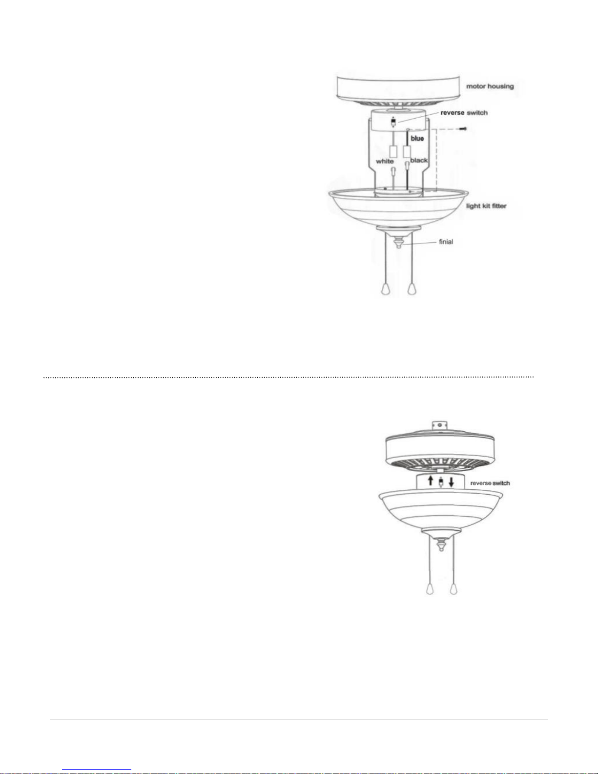
11. Light Kit Assembly.
Remove 3 screws from light kit fitter.
Plug the connector from light kit fitter
to the connector from switch housing.
Please note the correct wiring is
white to white
blue to black
Gently push connector into switch housing and align
holes in light kit fitter with holes in switch housing.
Secure light kit fitter to fan with the 3 screws that
were previously removed.
Attach the glass shade to the light kit fitter using the
finial you will find installed on the light kit pipe. Insert pull
chains through the holes on shade, and then attach the pull
chain FOB. Do not over tighten the finial.
Important: When replacing bulb(s), please allow
bulb(s) and glass shade(s) to cool down before
touching them.
Install: E12, Type B, 40W x 2 (Not Included)
WARNING: DO NOT EXCEED INDICATED BULB WATTAGE
NOTE: Your fan is equipped with a wattage limiter, if you exceed the indicated wattage your ceiling fan will not
function.
12. Testing Your Fan.
It is recommended that you test fan before finalizing installation.
Restore power from circuit box and light switch (if applicable).
Test fan speeds with pull chain and the reverse switch.
Start at the OFF position (no blade movement).
First pull will set the fan to HI.
Second pull will set the fan to MEDIUM.
Third pull will set the fan to LOW. Next pull will again set the
fan to OFF setting.
Test lights with pull chain in the middle. Start with all of the lights OFF.
The first pull will turn on only the UPPER lights in the lighting housing.
The second pull will turn on only the LOWER lights in the light kit.
The third pull will turn on ALL of the lights (upper and lower)
and the fourth pull will turn all of the lights OFF again.
If fan and /or lights do not function, please
refer to “Trouble shooting” section to solve any issues
before contacting Customer Service.
Turn fan completely off when moving the reverse switch.
Set reverse switch to recirculate air, depending on the season.
Pull chain extensions supplied, or a custom pull chain extension
(sold separately) can be attached to fan. Insert pull chain through
hole on shade then attach pull chain to pull chain FOB.
Page 11

MODEL NO.:RSS52
Page
11
TROUBLE SHOOTING
FAN DOES NOT START
1. Check all fuses or circuit breakers. Replace if MISSING.
2. Turn off electrical power and check all wire connections to fan and in switch
housing.
3. Make sure pull chain switch is on, and reverse slide switch is up or down, not in
the middle.
4. Unscrew the canopy and check all wire connectors, if the wire
connectors are loose, tighten it firmly.
FAN FOUND NOISY
1. Always take a few days" break in" time for any new fan at medium or high speed.
Try to diagnose the exact location of the noise by listening carefully from several
sides (blades, motor, light kit, etc). Fan noise can come from a light kit.
2. Make sure all screws in the fan assembly and light kit are tight and properly
threaded. If not, back out and retighten. Tighten these screws at least twice a year
because they may loosen slowly over time and cause clicking noise.
3. Make sure the light kit is securely fastened to the fan.
4. Make sure mounting bracket is installed securely to the outlet box.
5. Make sure wire nuts in switch housing or canopy are not rattling against each
other or against wall of housing. Wrap with electrical tape if necessary.
6. Use of standard light dimmer or unapproved wall control will always cause
harmonic distortions, or a humming noise. Many fan motors do not work quietly
with solid-state variable controls. If a quiet wall control is desired, use only
approved wall controls.
7. Make sure the canopy is not touching the ceiling.
8. Assure that the screws fastening blade holders to motor are tight
9. Make sure all light bulbs are fully screwed in.
FAN TURNS BUT DOES NOT MOVE MUCH AIR
1. The fan may be running in reverse, so air is directed upward.
2. The room may contain items that obstruct the airflow.
3. The fan may be too small for the size of the room.
FAN SHAKES OR WOBBLES
1. A small amount of wobble is considered acceptable and should not be
considered a defect. Use of any light kit, especially a large 4 or 5 light kit, will
usually induce some wobble.
2. Make sure mounting bracket is tight at junction box/ceiling with no movement at
all. Tighten screws if necessary.
3. Make sure all screws holding the blades to the blade arm and blade arm to
motor are tight.
4. Some fan movement is normal. However, interchanging an adjacent (side by
side) blade pair may redistribute the weight and result in smoother operation, if this is still unsuccessful
please refer to the next page.
Page 12

MODEL NO.:RSS52
Page
12
5. If the above does not eliminate the wobble, clip a balancing kit on any one of
blade about the middle of blade edge. Let fan run. If it is still wobbling, stop the
fan, and change the location. Repeating this procedure on the remaining blades
until the wobble is removed.
6. You can also look up at the fan from below, make sure that none of the blade
holders are bent so that a blade is out of position. Correction may be made by
GENTLY bending the blade holder back into position.
7. Blade tracking may be checked simply by use of a household yardstick as
shown in below Figure. Place the yardstick vertically against the ceiling and even
with the outside leading edge of a blade. Note the distance of the edge of a
blade same as others. Tum the blade slowly by hand to check the remaining
blades. If a blade is in an alignment, the blade holder may be gently bent up or
down to be in line with the other blades.
MAINTENANCE
1. The fan natural movements may cause some connections to work loose. A
clicking or rattling noise is a certain sign of loosening screws. Check the support
connections, brackets and blade attachment twice a year, and tighten all screws
as necessary. Make sure all screws attaching the glass screws are tightened.
2. Clean your fan periodically. Use only a damp cloth, never use solvents, and dust
with a soft cloth or brush. Metal finishes are finished with a lacquer to prevent tarnishing.
3. You will never need to oil your fan, its permanently sealed bearing will prevent
silent, trouble free operation for many years.
4. Make sure the power is turned off at the main fuse or circuit panel before you
attempt any repairs.
 Loading...